Rosemount 2120 Vibrating Fork Liquid Level Switch Vibrating Fork... · · 2011-11-22Product Data...
16
Product Data Sheet 00813-0100-4030, Rev FA November 2010 Rosemount 2120 www.rosemount.com • Function virtually unaffected by flow, bubbles, turbulence, foam, vibration, solids content, coating, properties of the liquid, and product variations • No need for calibration and requires minimum installation procedures • Easy terminal access, polarity insensitive and short circuit protection • No moving parts or crevices means virtually no maintenance • Electronic, self-checking, and condition monitoring - Heartbeat LED gives status and health information • Adjustable Switching Delay for turbulent/splashing applications • Magnetic test point makes functional test easy • Small in size and weight • “Fast Drip” Fork Design gives quicker response time especially with viscous liquids • Explosion-proof/Flameproof and Intrinsically Safe options • SIL 2 of IEC 61508 • DIBt/WHG overfill protection Contents Reliable Performance...In Challenging Applications . . . . . . . . . . . . . . . . . . . . . . . . . page 2 Rosemount 2120 Vibrating Fork Liquid Level Switch . . . . . . . . . . . . . . . . . . . . . . . . page 4 Specifications . . . . . . . . . . . . . . . . . . . . . . . . . . . . . . . . . . . . . . . . . . . . . . . . . . . . . . page 8 Product Certifications . . . . . . . . . . . . . . . . . . . . . . . . . . . . . . . . . . . . . . . . . . . . . . . page 10 Dimensional Drawings. . . . . . . . . . . . . . . . . . . . . . . . . . . . . . . . . . . . . . . . . . . . . . . page 12 Rosemount 2120 Vibrating Fork Liquid Level Switch
Transcript of Rosemount 2120 Vibrating Fork Liquid Level Switch Vibrating Fork... · · 2011-11-22Product Data...
Product Data Sheet00813-0100-4030, Rev FANovember 2010 Rosemount 2120
www.rosemount.com
• Function virtually unaffected by flow, bubbles, turbulence, foam, vibration, solids content, coating, properties of the liquid, and product variations
• No need for calibration and requires minimum installation procedures
• Easy terminal access, polarity insensitive and short circuit protection
• No moving parts or crevices means virtually no maintenance
• Electronic, self-checking, and condition monitoring - Heartbeat LED gives status and health information
• Adjustable Switching Delay for turbulent/splashing applications
• Magnetic test point makes functional test easy
• Small in size and weight
• “Fast Drip” Fork Design gives quicker response time especially with viscous liquids
• Explosion-proof/Flameproof and Intrinsically Safe options
• SIL 2 of IEC 61508
• DIBt/WHG overfill protection
Contents
Reliable Performance...In Challenging Applications . . . . . . . . . . . . . . . . . . . . . . . . . page 2
Rosemount 2120 Vibrating Fork Liquid Level Switch . . . . . . . . . . . . . . . . . . . . . . . . page 4
Specifications . . . . . . . . . . . . . . . . . . . . . . . . . . . . . . . . . . . . . . . . . . . . . . . . . . . . . . page 8
Product Certifications . . . . . . . . . . . . . . . . . . . . . . . . . . . . . . . . . . . . . . . . . . . . . . . page 10
Dimensional Drawings. . . . . . . . . . . . . . . . . . . . . . . . . . . . . . . . . . . . . . . . . . . . . . . page 12
Rosemount 2120 Vibrating Fork Liquid Level Switch
Product Data Sheet00813-0100-4030, Rev FA
November 2010Rosemount 2120
2
Reliable Performance...In Challenging Applications
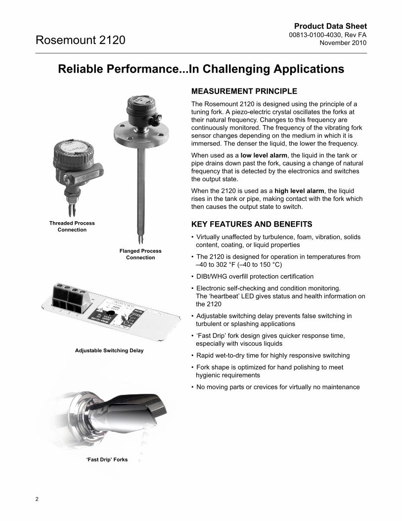
MEASUREMENT PRINCIPLE
The Rosemount 2120 is designed using the principle of a tuning fork. A piezo-electric crystal oscillates the forks at their natural frequency. Changes to this frequency are continuously monitored. The frequency of the vibrating fork sensor changes depending on the medium in which it is immersed. The denser the liquid, the lower the frequency.
When used as a low level alarm, the liquid in the tank or pipe drains down past the fork, causing a change of natural frequency that is detected by the electronics and switches the output state.
When the 2120 is used as a high level alarm, the liquid rises in the tank or pipe, making contact with the fork which then causes the output state to switch.
KEY FEATURES AND BENEFITS
• Virtually unaffected by turbulence, foam, vibration, solids content, coating, or liquid properties
• The 2120 is designed for operation in temperatures from –40 to 302 °F (–40 to 150 °C)
• DIBt/WHG overfill protection certification
• Electronic self-checking and condition monitoring.The ‘heartbeat’ LED gives status and health information on the 2120
• Adjustable switching delay prevents false switching in turbulent or splashing applications
• ‘Fast Drip’ fork design gives quicker response time, especially with viscous liquids
• Rapid wet-to-dry time for highly responsive switching
• Fork shape is optimized for hand polishing to meet hygienic requirements
• No moving parts or crevices for virtually no maintenance
‘Fast Drip’ Forks
Adjustable Switching Delay
Threaded Process Connection
Flanged Process Connection
Product Data Sheet00813-0100-4030, Rev FANovember 2010
3
Rosemount 2120
Fit and Forget
• Once installed, the 2120 is ready to go. It needs no calibration and requires minimum installation
• The ‘heartbeat’ LED gives an instant visual indication that the unit is operational
• Functional testing of the instrument and system is easy with a magnetic test point
• You can install, and forget it
Superior Performance
• The 2120 is a popular choice for high and low level alarm and pump control duties for its simplicity, ease of use, and reliability
• Functionality is virtually unaffected by flow, turbulence, bubbles, foam, or vibration
• The ‘Fast Drip’ design allows the liquid to be quickly drawn away from the fork tip, making the 2120 quicker and more responsive in high density or viscous liquid applications
• With a user-selectable time delay feature, the risk of false switching is minimized in turbulent or splashing applications
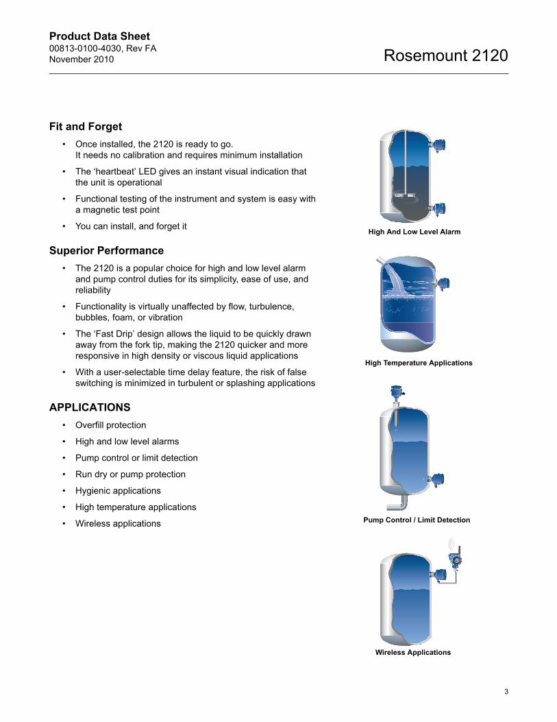
APPLICATIONS
• Overfill protection
• High and low level alarms
• Pump control or limit detection
• Run dry or pump protection
• Hygienic applications
• High temperature applications
• Wireless applications
High And Low Level Alarm
High Temperature Applications
Pump Control / Limit Detection
Wireless Applications
Product Data Sheet00813-0100-4030, Rev FA
November 2010Rosemount 2120
4
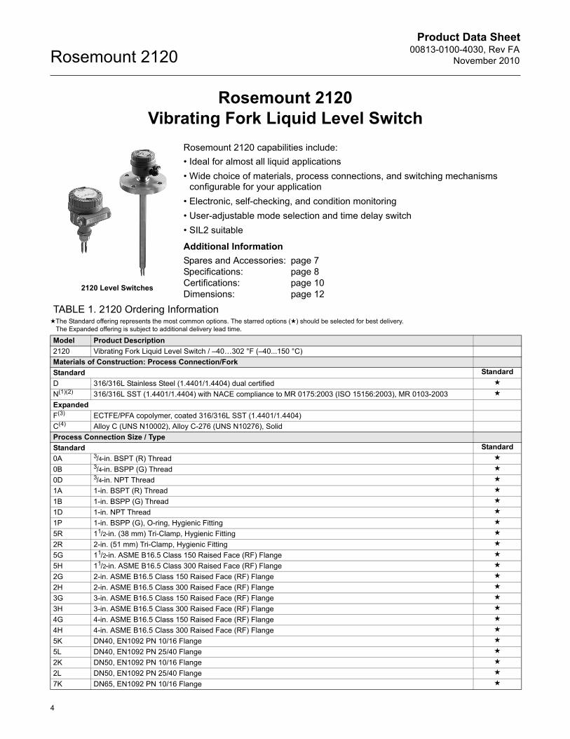
Rosemount 2120Vibrating Fork Liquid Level Switch
Rosemount 2120 capabilities include:
• Ideal for almost all liquid applications
• Wide choice of materials, process connections, and switching mechanisms configurable for your application
• Electronic, self-checking, and condition monitoring
• User-adjustable mode selection and time delay switch
• SIL2 suitable
Additional Information
Spares and Accessories: page 7Specifications: page 8Certifications: page 10Dimensions: page 12
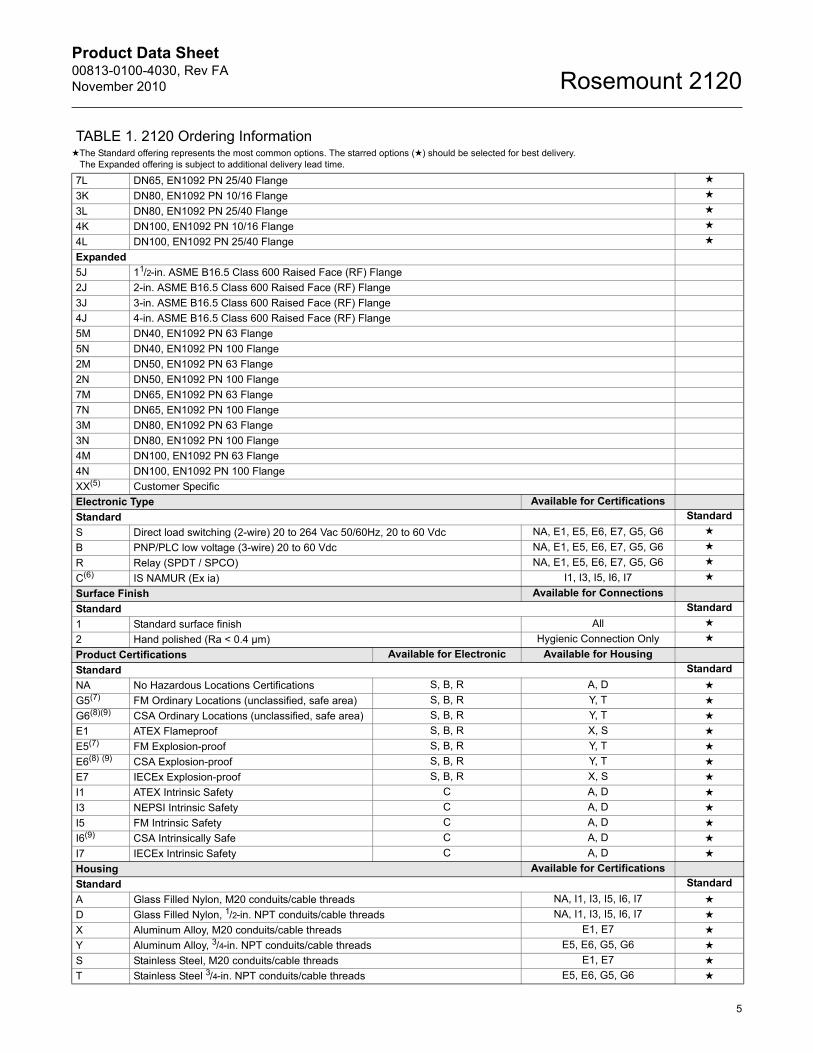
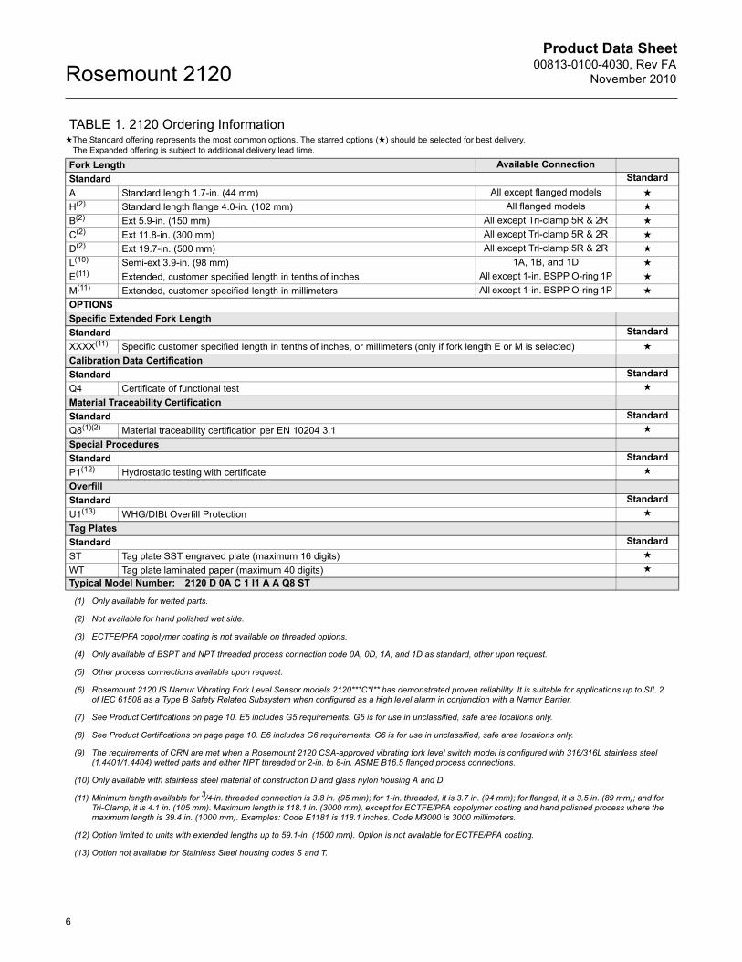
TABLE 1. 2120 Ordering Information★The Standard offering represents the most common options. The starred options (★) should be selected for best delivery.
The Expanded offering is subject to additional delivery lead time.
Model Product Description
2120 Vibrating Fork Liquid Level Switch / –40…302 °F (–40...150 °C)
Materials of Construction: Process Connection/Fork
Standard Standard
D 316/316L Stainless Steel (1.4401/1.4404) dual certified ★
N(1)(2) 316/316L SST (1.4401/1.4404) with NACE compliance to MR 0175:2003 (ISO 15156:2003), MR 0103-2003 ★
Expanded
F(3) ECTFE/PFA copolymer, coated 316/316L SST (1.4401/1.4404)
C(4) Alloy C (UNS N10002), Alloy C-276 (UNS N10276), Solid
Process Connection Size / Type
Standard Standard
0A 3/4-in. BSPT (R) Thread ★
0B 3/4-in. BSPP (G) Thread ★
0D 3/4-in. NPT Thread ★
1A 1-in. BSPT (R) Thread ★
1B 1-in. BSPP (G) Thread ★
1D 1-in. NPT Thread ★
1P 1-in. BSPP (G), O-ring, Hygienic Fitting ★
5R 11/2-in. (38 mm) Tri-Clamp, Hygienic Fitting ★
2R 2-in. (51 mm) Tri-Clamp, Hygienic Fitting ★
5G 11/2-in. ASME B16.5 Class 150 Raised Face (RF) Flange ★
5H 11/2-in. ASME B16.5 Class 300 Raised Face (RF) Flange ★
2G 2-in. ASME B16.5 Class 150 Raised Face (RF) Flange ★
2H 2-in. ASME B16.5 Class 300 Raised Face (RF) Flange ★
3G 3-in. ASME B16.5 Class 150 Raised Face (RF) Flange ★
3H 3-in. ASME B16.5 Class 300 Raised Face (RF) Flange ★
4G 4-in. ASME B16.5 Class 150 Raised Face (RF) Flange ★
4H 4-in. ASME B16.5 Class 300 Raised Face (RF) Flange ★
5K DN40, EN1092 PN 10/16 Flange ★
5L DN40, EN1092 PN 25/40 Flange ★
2K DN50, EN1092 PN 10/16 Flange ★
2L DN50, EN1092 PN 25/40 Flange ★
7K DN65, EN1092 PN 10/16 Flange ★
2120 Level Switches
Product Data Sheet00813-0100-4030, Rev FANovember 2010
5
Rosemount 2120
7L DN65, EN1092 PN 25/40 Flange ★
3K DN80, EN1092 PN 10/16 Flange ★
3L DN80, EN1092 PN 25/40 Flange ★
4K DN100, EN1092 PN 10/16 Flange ★
4L DN100, EN1092 PN 25/40 Flange ★
Expanded
5J 11/2-in. ASME B16.5 Class 600 Raised Face (RF) Flange
2J 2-in. ASME B16.5 Class 600 Raised Face (RF) Flange
3J 3-in. ASME B16.5 Class 600 Raised Face (RF) Flange
4J 4-in. ASME B16.5 Class 600 Raised Face (RF) Flange
5M DN40, EN1092 PN 63 Flange
5N DN40, EN1092 PN 100 Flange
2M DN50, EN1092 PN 63 Flange
2N DN50, EN1092 PN 100 Flange
7M DN65, EN1092 PN 63 Flange
7N DN65, EN1092 PN 100 Flange
3M DN80, EN1092 PN 63 Flange
3N DN80, EN1092 PN 100 Flange
4M DN100, EN1092 PN 63 Flange
4N DN100, EN1092 PN 100 Flange
XX(5) Customer Specific
Electronic Type Available for Certifications
Standard Standard
S Direct load switching (2-wire) 20 to 264 Vac 50/60Hz, 20 to 60 Vdc NA, E1, E5, E6, E7, G5, G6 ★
B PNP/PLC low voltage (3-wire) 20 to 60 Vdc NA, E1, E5, E6, E7, G5, G6 ★
R Relay (SPDT / SPCO) NA, E1, E5, E6, E7, G5, G6 ★
C(6) IS NAMUR (Ex ia) I1, I3, I5, I6, I7 ★
Surface Finish Available for Connections
Standard Standard
1 Standard surface finish All ★
2 Hand polished (Ra < 0.4 µm) Hygienic Connection Only ★
Product Certifications Available for Electronic Available for Housing
Standard Standard
NA No Hazardous Locations Certifications S, B, R A, D ★
G5(7) FM Ordinary Locations (unclassified, safe area) S, B, R Y, T ★
G6(8)(9) CSA Ordinary Locations (unclassified, safe area) S, B, R Y, T ★
E1 ATEX Flameproof S, B, R X, S ★
E5(7) FM Explosion-proof S, B, R Y, T ★
E6(8) (9) CSA Explosion-proof S, B, R Y, T ★
E7 IECEx Explosion-proof S, B, R X, S ★
I1 ATEX Intrinsic Safety C A, D ★
I3 NEPSI Intrinsic Safety C A, D ★
I5 FM Intrinsic Safety C A, D ★
I6(9) CSA Intrinsically Safe C A, D ★
I7 IECEx Intrinsic Safety C A, D ★
Housing Available for Certifications
Standard Standard
A Glass Filled Nylon, M20 conduits/cable threads NA, I1, I3, I5, I6, I7 ★
D Glass Filled Nylon, 1/2-in. NPT conduits/cable threads NA, I1, I3, I5, I6, I7 ★
X Aluminum Alloy, M20 conduits/cable threads E1, E7 ★
Y Aluminum Alloy, 3/4-in. NPT conduits/cable threads E5, E6, G5, G6 ★
S Stainless Steel, M20 conduits/cable threads E1, E7 ★
T Stainless Steel 3/4-in. NPT conduits/cable threads E5, E6, G5, G6 ★
TABLE 1. 2120 Ordering Information★The Standard offering represents the most common options. The starred options (★) should be selected for best delivery.
The Expanded offering is subject to additional delivery lead time.
Product Data Sheet00813-0100-4030, Rev FA
November 2010Rosemount 2120
6
Fork Length Available Connection
Standard Standard
A Standard length 1.7-in. (44 mm) All except flanged models ★
H(2) Standard length flange 4.0-in. (102 mm) All flanged models ★
B(2) Ext 5.9-in. (150 mm) All except Tri-clamp 5R & 2R ★
C(2) Ext 11.8-in. (300 mm) All except Tri-clamp 5R & 2R ★
D(2) Ext 19.7-in. (500 mm) All except Tri-clamp 5R & 2R ★
L(10) Semi-ext 3.9-in. (98 mm) 1A, 1B, and 1D ★
E(11) Extended, customer specified length in tenths of inches All except 1-in. BSPP O-ring 1P ★
M(11) Extended, customer specified length in millimeters All except 1-in. BSPP O-ring 1P ★
OPTIONS
Specific Extended Fork Length
Standard Standard
XXXX(11) Specific customer specified length in tenths of inches, or millimeters (only if fork length E or M is selected) ★
Calibration Data Certification
Standard Standard
Q4 Certificate of functional test ★
Material Traceability Certification
Standard Standard
Q8(1)(2) Material traceability certification per EN 10204 3.1 ★
Special Procedures
Standard Standard
P1(12) Hydrostatic testing with certificate ★
Overfill
Standard Standard
U1(13) WHG/DIBt Overfill Protection ★
Tag Plates
Standard Standard
ST Tag plate SST engraved plate (maximum 16 digits) ★
WT Tag plate laminated paper (maximum 40 digits) ★
Typical Model Number: 2120 D 0A C 1 I1 A A Q8 ST
(1) Only available for wetted parts.
(2) Not available for hand polished wet side.
(3) ECTFE/PFA copolymer coating is not available on threaded options.
(4) Only available of BSPT and NPT threaded process connection code 0A, 0D, 1A, and 1D as standard, other upon request.
(5) Other process connections available upon request.
(6) Rosemount 2120 IS Namur Vibrating Fork Level Sensor models 2120***C*I** has demonstrated proven reliability. It is suitable for applications up to SIL 2 of IEC 61508 as a Type B Safety Related Subsystem when configured as a high level alarm in conjunction with a Namur Barrier.
(7) See Product Certifications on page 10. E5 includes G5 requirements. G5 is for use in unclassified, safe area locations only.
(8) See Product Certifications on page page 10. E6 includes G6 requirements. G6 is for use in unclassified, safe area locations only.
(9) The requirements of CRN are met when a Rosemount 2120 CSA-approved vibrating fork level switch model is configured with 316/316L stainless steel (1.4401/1.4404) wetted parts and either NPT threaded or 2-in. to 8-in. ASME B16.5 flanged process connections.
(10) Only available with stainless steel material of construction D and glass nylon housing A and D.
(11) Minimum length available for 3/4-in. threaded connection is 3.8 in. (95 mm); for 1-in. threaded, it is 3.7 in. (94 mm); for flanged, it is 3.5 in. (89 mm); and for Tri-Clamp, it is 4.1 in. (105 mm). Maximum length is 118.1 in. (3000 mm), except for ECTFE/PFA copolymer coating and hand polished process where the maximum length is 39.4 in. (1000 mm). Examples: Code E1181 is 118.1 inches. Code M3000 is 3000 millimeters.
(12) Option limited to units with extended lengths up to 59.1-in. (1500 mm). Option is not available for ECTFE/PFA coating.
(13) Option not available for Stainless Steel housing codes S and T.
TABLE 1. 2120 Ordering Information★The Standard offering represents the most common options. The starred options (★) should be selected for best delivery.
The Expanded offering is subject to additional delivery lead time.
Product Data Sheet00813-0100-4030, Rev FANovember 2010
7
Rosemount 2120
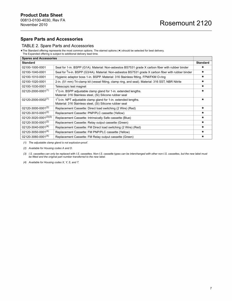
Spare Parts and Accessories
TABLE 2. Spare Parts and Accessories★The Standard offering represents the most common options. The starred options (★) should be selected for best delivery.
The Expanded offering is subject to additional delivery lead time.
Spares and Accessories
Standard Standard
02100-1000-0001 Seal for 1-in. BSPP (G1A). Material: Non-asbestos BS7531 grade X carbon fiber with rubber binder ★
02100-1040-0001 Seal for 3/4-in. BSPP (G3/4A). Material: Non-asbestos BS7531 grade X carbon fiber with rubber binder ★
02100-1010-0001 Hygienic adaptor boss 1-in. BSPP. Material: 316 Stainless fitting. FPM/FKM O-ring ★
02100-1020-0001 2-in. (51 mm) Tri-clamp kit (vessel fitting, clamp ring, and seal). Material: 316 SST, NBR Nitrile ★
02100-1030-0001 Telescopic test magnet ★
02120-2000-0001(1) 11/2-in. BSPP adjustable clamp gland for 1-in. extended lengths.Material: 316 Stainless steel, (Si) Silicone rubber seal
★
02120-2000-0002(1) 11/2-in. NPT adjustable clamp gland for 1-in. extended lengths.Material: 316 Stainless steel, (Si) Silicone rubber seal
★
02120-3000-0001(2) Replacement Cassette: Direct load switching (2 Wire) (Red) ★
02120-3010-0001(2) Replacement Cassette: PNP/PLC cassette (Yellow) ★
02120-3020-0001(2)(3) Replacement Cassette: Intrinsically Safe cassette (Blue) ★
02120-3030-0001(2) Replacement Cassette: Relay output cassette (Green) ★
02120-3040-0001(4) Replacement Cassette: FM Direct load switching (2 Wire) (Red) ★
02120-3050-0001(4) Replacement Cassette: FM PNP/PLC cassette (Yellow) ★
02120-3060-0001(4) Replacement Cassette: FM Relay output cassette (Green) ★
(1) The adjustable clamp gland is not explosion-proof.
(2) Available for Housing codes A and D.
(3) I.S. cassettes can only be replaced with I.S. cassettes. Non-I.S. cassette types can be interchanged with other non-I.S. cassettes, but the new label must be fitted and the original part number transferred to the new label.
(4) Available for Housing codes X, Y, S, and T.
Product Data Sheet00813-0100-4030, Rev FA
November 2010Rosemount 2120
8
Specifications
Physical
ProductRosemount 2120 Vibrating Fork Liquid Level Switch
Measuring principleVibrating Fork
ApplicationsMost liquids including coating liquids, aerated liquids, and slurries
Mechanical
Housing and Enclosure
ConnectionsSee Process Connection Size / Type on page 4
Extended LengthsThe maximum extended length is 118.1 in. (3000 mm) except for a hand-polished 2120 that is limited to 39.4 in. (1000 mm)
Process Material316/316L Stainless Steel (1.4401/1.4404 dual certified), Alloy C (UNS N10002) and Alloy C-276 (UNS N10276), orECTFE/PFA co-polymer coated 316/316L Stainless Steel (1.4401/1.4404 dual certified)
Hand polished to better than 0.4 m option available for hygienic connections
Gasket material for 3/4-in. and 1-in. BSPP (G) is Non-asbestos BS7531 Grade X carbon fiber with rubber binder
Dimensional DrawingsSee Dimensional Drawings on page 12
Performance
Hysteresis (water)±0.039-in. (±1 mm) nominal
Switching Point (water)0.5 in. (13 mm) from tip (vertical) / from edge (horizontal) of fork (this will vary with different liquid densities)
Functional
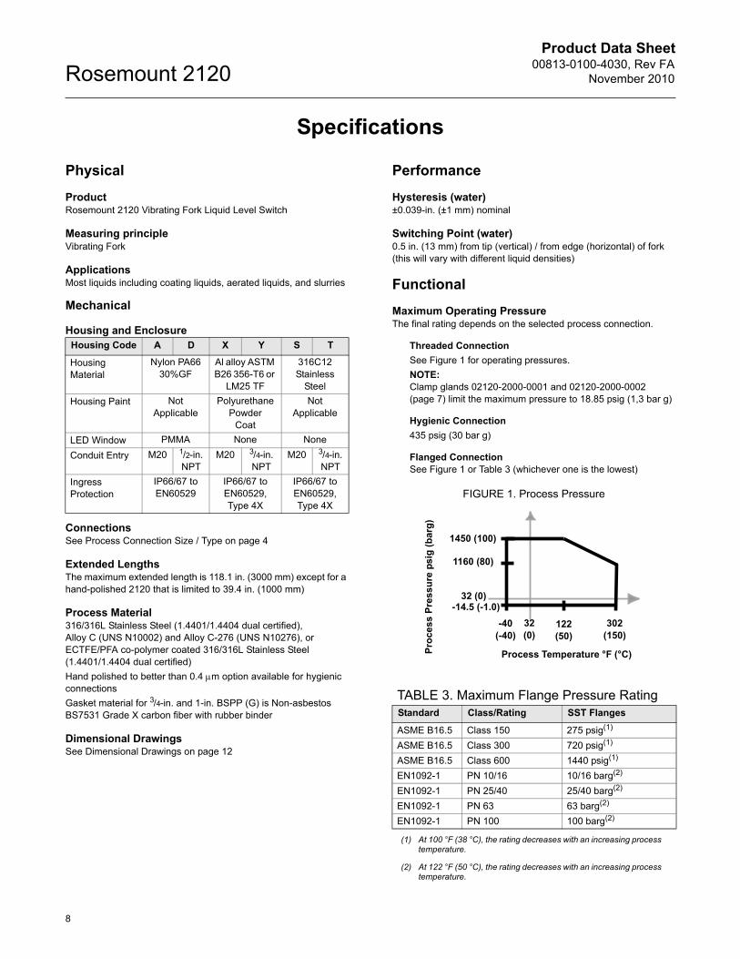
Maximum Operating PressureThe final rating depends on the selected process connection.
Threaded Connection
See Figure 1 for operating pressures.
NOTE:Clamp glands 02120-2000-0001 and 02120-2000-0002 (page 7) limit the maximum pressure to 18.85 psig (1,3 bar g)
Hygienic Connection
435 psig (30 bar g)
Flanged Connection See Figure 1 or Table 3 (whichever one is the lowest)
FIGURE 1. Process Pressure
Housing Code A D X Y S T
Housing Material
Nylon PA66 30%GF
Al alloy ASTM B26 356-T6 or
LM25 TF
316C12 Stainless
Steel
Housing Paint Not Applicable
Polyurethane Powder
Coat
Not Applicable
LED Window PMMA None None
Conduit Entry M20 1/2-in. NPT
M20 3/4-in. NPT
M20 3/4-in. NPT
Ingress Protection
IP66/67 to EN60529
IP66/67 to EN60529, Type 4X
IP66/67 to EN60529, Type 4X
TABLE 3. Maximum Flange Pressure RatingStandard Class/Rating SST Flanges
ASME B16.5 Class 150 275 psig(1)
(1) At 100 °F (38 °C), the rating decreases with an increasing process temperature.
ASME B16.5 Class 300 720 psig(1)
ASME B16.5 Class 600 1440 psig(1)
EN1092-1 PN 10/16 10/16 barg(2)
EN1092-1 PN 25/40 25/40 barg(2)
EN1092-1 PN 63 63 barg(2)
(2) At 122 °F (50 °C), the rating decreases with an increasing process temperature.
EN1092-1 PN 100 100 barg(2)
1450 (100)
1160 (80)
-14.5 (-1.0)
-40 (-40)
122 (50)
302 (150)
Process Temperature °F (°C)Pro
cess
Pre
ssu
re p
sig
(b
arg
)
32 (0)
32 (0)
Product Data Sheet00813-0100-4030, Rev FANovember 2010
9
Rosemount 2120
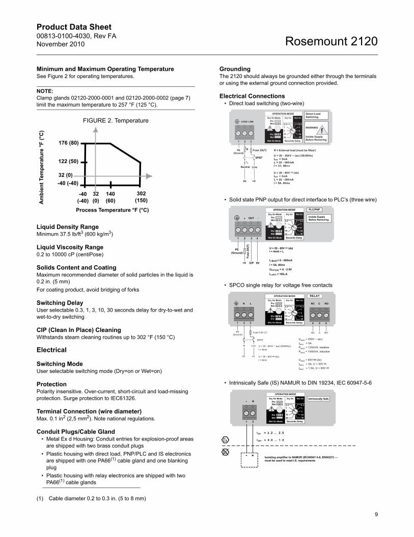
Minimum and Maximum Operating TemperatureSee Figure 2 for operating temperatures.
NOTE:Clamp glands 02120-2000-0001 and 02120-2000-0002 (page 7) limit the maximum temperature to 257 °F (125 °C).
FIGURE 2. Temperature
Liquid Density RangeMinimum 37.5 lb/ft3 (600 kg/m3)
Liquid Viscosity Range0.2 to 10000 cP (centiPose)
Solids Content and CoatingMaximum recommended diameter of solid particles in the liquid is 0.2 in. (5 mm)
For coating product, avoid bridging of forks
Switching DelayUser selectable 0.3, 1, 3, 10, 30 seconds delay for dry-to-wet and wet-to-dry switching
CIP (Clean In Place) CleaningWithstands steam cleaning routines up to 302 °F (150 °C)
Electrical
Switching ModeUser selectable switching mode (Dry=on or Wet=on)
ProtectionPolarity insensitive. Over-current, short-circuit and load-missing protection. Surge protection to IEC61326.
Terminal Connection (wire diameter)Max. 0.1 in2 (2,5 mm2). Note national regulations.
Conduit Plugs/Cable Gland• Metal Ex d Housing: Conduit entries for explosion-proof areas
are shipped with two brass conduit plugs
• Plastic housing with direct load, PNP/PLC and IS electronics are shipped with one PA66(1) cable gland and one blanking plug
• Plastic housing with relay electronics are shipped with two PA66(1) cable glands
GroundingThe 2120 should always be grounded either through the terminals or using the external ground connection provided.
Electrical Connections• Direct load switching (two-wire)
• Solid state PNP output for direct interface to PLC’s (three wire)
• SPCO single relay for voltage free contacts
• Intrinsically Safe (IS) NAMUR to DIN 19234, IEC 60947-5-6
(1) Cable diameter 0.2 to 0.3 in. (5 to 8 mm)
176 (80)
140 (60)
-40 (-40)
-40 (-40)
302 (150)
Process Temperature °F (°C)
Am
bie
nt
Tem
per
atu
re °
F (
°C)
122 (50)
32 (0)
32 (0)
Direct LoadSwitching
WARNING
Isolate SupplyBefore Removing
OPERATION MODE
Dry On ModeDryWet
Wet On Mode
DryWet
Dry On Wet On
Seconds Delay
0.3 0.3
3
3010
1
3
3010
1
1 2 3
LINELOAD
PE(Ground)
Neutral Live
0V
Fuse 2A(T)R
IL
R = External load (must be fitted )
U = 20 - 264V ~ (ac) (50/60Hz)IOFF < 3mAIL = 20 - 500mAî = 5A, 40ms
U = 20 - 60V (dc))IOFF < 3mAIL = 20 - 500mAî = 5A, 40ms
DPST
+V
OPERATION MODE
Dry On ModeDryWet
Wet On Mode
DryWet
Dry On Wet On
Seconds Delay
0.3 0.3
3
3010
1
3
3010
1
1 2 3
OUT+ -
4
PLC/PNP
Isolate SupplyBefore Removing
PE(Ground)
0VO/P
U = 20 - 60V (dc)I < 4mA + IL
IL (MAX) = 0 - 500mAî = 5A, 40msUOUT(ON) = U - 2.5VIL (OFF) < 100µA
+V
Fuse
2A
(T)
OPERATION MODE
Dry On ModeDryWet
Wet On Mode
DryWet
Dry On Wet On
Seconds Delay
0.3 0.3
3
3010
1
3
3010
1
4 5 6
NOCNC
RELAY
1 2 3
LN
PE(Ground)
N
0V
Fuse 0.5A (T)
Live
+V
U = 20 - 264V ~ (ac) (50/60Hz)I < 6mA
U = 20 - 60V (dc)I < 6mA
NC C NO
UMAX = 250V ~ (ac)IMAX = 5APMAX' = 1250VA, resistive PMAX' = 1000VA, inductive
UMAX = 60V (dc)IMAX = 5A, U < 30VIMAX = 1.5A, U < 60V
DPST
OPERATION MODE
Dry On ModeDryWet
Wet On Mode
DryWet
Dry On Wet On
Seconds Delay
0.3 0.3
3
3010
13
3010
1
1 2
+-Intrinsically Safe
I ON = 2 .2 ... 2 .5
I OFF = 0 .8 ... 1 .0
+- Isolating amplifier to NAMUR (IEC60947-5-6, EN50227) —must be used to meet I.S. requirements
Product Data Sheet00813-0100-4030, Rev FA
November 2010Rosemount 2120
10
Product Certifications
ORDINARY LOCATION CERTIFICATION FOR FMG5 Project ID: 3024095
The switch has been examined and tested to determine that the design meets basic electrical, mechanical, and fire protection requirements by FM, a nationally recognized testing laboratory (NRTL) as accredited by the Federal Occupational Safety and Health Administration (OSHA).
ORDINARY LOCATION CERTIFICATION FOR CSAG6 Certificate Number: 06 CSA 1796535
The switch has been examined and tested to determine that the design meets basic electrical, mechanical, and fire protection requirements by CSA, a nationally recognized testing laboratory as accredited by the Standards Council of Canada (SCC).
EUROPEAN DIRECTIVE INFORMATIONThe EC declaration of conformity for all applicable European directives for this product can be found on the Rosemount website at www.rosemount.com. A hard copy may be obtained by contacting your local sales office.
ATEX Directive (94/9/EC)Complies with the ATEX Directive.
Pressure Equipment Directive (PED) (97/23/EC)The Rosemount 2120 is outside the scope of PED Directive.
L.V. DirectiveEN61010-1 Pollution degree 2, Category II (264V max), Pollution degree 2, Category III (150V max)
Electro Magnetic Compatibility (EMC) DirectiveEN61326 Emissions to Class B.
Immunity to industrial location requirements.
Vibration ResistanceEN60721 level 3M6/4M6
CE-markComplies with applicable directives (EMC, ATEX, and LVD)
Overfill ProtectionIf required, select Product Certificates code U1 for WHG/DIBt overfill protection. The approval number is Z-65.11-236.
SIL Declaration of ConformityThe Rosemount 2120 IS Namur Vibrating Fork Level Sensor(2120***C*I**) has demonstrated proven reliability. It is manufactured and supported in a manner suitable for applications up to SIL 2 of IEC 61508 as a Type B Safety Related Subsystem when configured(1) as a high level alarm in conjunction with a Namur Barrier.
HAZARDOUS LOCATIONS CERTIFICATIONS
North American Approvals
Factory Mutual (FM) Explosion-proof ApprovalE5 Project ID: 3024095
Explosion-proof for Class I, Div. 1, Groups A, B, C, and DTemperature Class:T6 (Tamb –40 to 75 °C)Enclosure: Type 4X
Factory Mutual (FM) Intrinsically Safe ApprovalI5 Project ID: 3024095
Intrinsically Safe for Class I, Div. 1, Groups A, B, C, and DClass I, Zone 0, AEx ia IICTemperature Code:T5 (Tamb –40 to 80 °C, Tproc < 80 °C)Control Drawing: 71097/1154Ui=15 V, Ii=32 mA, Pi=0.1 W, Ci=211 nF, Li=0.06 mH
NOTEA NAMUR isolating amplifier must be used for intrinsic safety.
Canadian Approvals
Canadian Standards Association (CSA)Explosion-proof ApprovalsE6 Project ID: 1796535
Explosion-proof for Class I, Div. 1, Groups A, B, C, and DTemperature Class:T6 (Tamb –40 to 75 °C)Enclosure: Type 4X
Canadian Standards Association (CSA)Intrinsically Safe ApprovalI6 Certificate Number: 06 CSA 1796535
Intrinsically Safe for Class I, Div. 1, Groups A, B, C, and DClass 1, Zone 0, Ex ia IICTemperature Code:T5 (Tamb –40 to 80 °C, Tproc < 80 °C)Control Drawing: 71097/1179Ui=15 V, Ii=32 mA, Pi=0.1 W, Ci=211 nF, Li=0.06 mH
(1) Refer to manual for IEC 61508 configuration details.
Product Data Sheet00813-0100-4030, Rev FANovember 2010
11
Rosemount 2120
Canadian Standards Association (CSA)Non-Incendive ApprovalI6 Certificate Number: 06 CSA 1796535
Non-Incendive for Class I, Div. 2, Groups A, B, C, and DTemperature Code:T5 (Tamb –40 to 80 °C, Tproc < 80 °C)Control Drawing: 71097/1187Ui=15 V, Ii=32 mA, Pi=0.1 W, Ci=211 nF, Li=0.06 mH
NOTEA NAMUR isolating amplifier must be used for intrinsic safety.
Canadian Registration Number (CRN)CRN 0F04227.2C
NOTEThe requirements of CRN are met when a Rosemount 2120 CSA-approved vibrating fork level switch model is configured with 316/316L stainless steel (1.4401/1.4404) wetted parts and either NPT threaded or 2-in. to 8-in. ASME B16.5 flanged process connections.
European Approvals
ATEX Flameproof ApprovalE1 Certificate: Sira 05ATEX1129X
Flameproof and Dust:ATEX Marking II 1/2 G DEx d IIC T6 to T2Ex tD A21 (T85°C to 265°C) IP6X
ATEX Intrinsically Safe ApprovalI1 Certificate: Sira 05ATEX2130X
Intrinsic Safety and Dust:ATEX Marking II 1 G DEx ia IIC T5 to T2Ex iaD 20 (T85 °C to 265 °C) IP6XUi=15 V, Ii=32 mA, Pi=0.1 W, Ci=12 nF, Li=0.06 mH
NOTEA NAMUR isolating amplifier must be used for intrinsic safety.
International Approvals
National Supervision and Inspection Centre for Explosion Protection and Safety Instrumentation (NEPSI) Intrinsically Safe ApprovalI3 Certificates:
GYJ06530 (when manufactured in Slough, UK)GYJ06531 (when manufactured in Singapore, Singapore)Intrinsic Safety:Ex ia IIC T5 (Tamb –40 to 60 °C)
Ui=15 V, Ii=32 mA, Pi=0.1 W, Ci=12 nF, Li=0.06 mH
NOTEA NAMUR isolating amplifier must be used for intrinsic safety.
International Electrotechnical Commission (IEC) Flameproof ApprovalE7 Certificate: IECEx SIR 06.0051X
Flameproof and Dust:Zone 0/1Ex d IIC T6 to T2Ex tD A21 (T85 °C to 265 °C) IP6X
International Electrotechnical Commission (IEC) Intrinsically Safe ApprovalI7 Certificate: IECEx SIR 06.0070X
Intrinsically Safe and Dust:Ex ia IIC T5 to T2Ex iaD 20 (T85 °C to 265 °C) IP6XUi=15 V, Ii=32 mA, Pi=0.1 W, Ci=12 nF, Li=0.06 mH
NOTEA NAMUR isolating amplifier must be used for intrinsic safety.
Product Data Sheet00813-0100-4030, Rev FA
November 2010Rosemount 2120
12
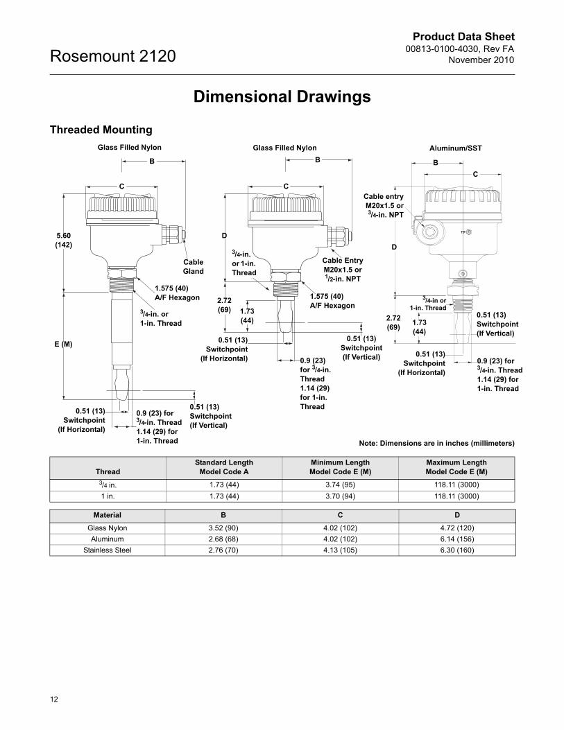
Dimensional Drawings
Threaded Mounting
Note: Dimensions are in inches (millimeters)
C
Cable entryM20x1.5 or3/4-in. NPT
B
D
0.51 (13)Switchpoint (If Vertical)
B
C
D
2.72(69) 1.73
(44)
Cable Entry M20x1.5 or 1/2-in. NPT
1.575 (40)A/F Hexagon
0.9 (23) for 3/4-in. Thread1.14 (29) for 1-in. Thread
0.51 (13)Switchpoint (If Vertical)
B
C
Cable Gland
1.575 (40)A/F Hexagon
5.60(142)
0.51 (13)Switchpoint (If Vertical)
0.9 (23) for 3/4-in. Thread1.14 (29) for 1-in. Thread
0.9 (23) for 3/4-in. Thread1.14 (29) for 1-in. Thread
1.73(44)
2.72(69)
E (M)
3/4-in or1-in. Thread
Glass Filled Nylon Aluminum/SSTGlass Filled Nylon
0.51 (13)Switchpoint
(If Horizontal)
0.51 (13)Switchpoint
(If Horizontal)0.51 (13)
Switchpoint(If Horizontal)
3/4-in. or 1-in. Thread
3/4-in.or 1-in. Thread
ThreadStandard Length
Model Code AMinimum LengthModel Code E (M)
Maximum Length Model Code E (M)
3/4 in. 1.73 (44) 3.74 (95) 118.11 (3000)
1 in. 1.73 (44) 3.70 (94) 118.11 (3000)
Material B C D
Glass Nylon 3.52 (90) 4.02 (102) 4.72 (120)
Aluminum 2.68 (68) 4.02 (102) 6.14 (156)
Stainless Steel 2.76 (70) 4.13 (105) 6.30 (160)
Product Data Sheet00813-0100-4030, Rev FANovember 2010
13
Rosemount 2120
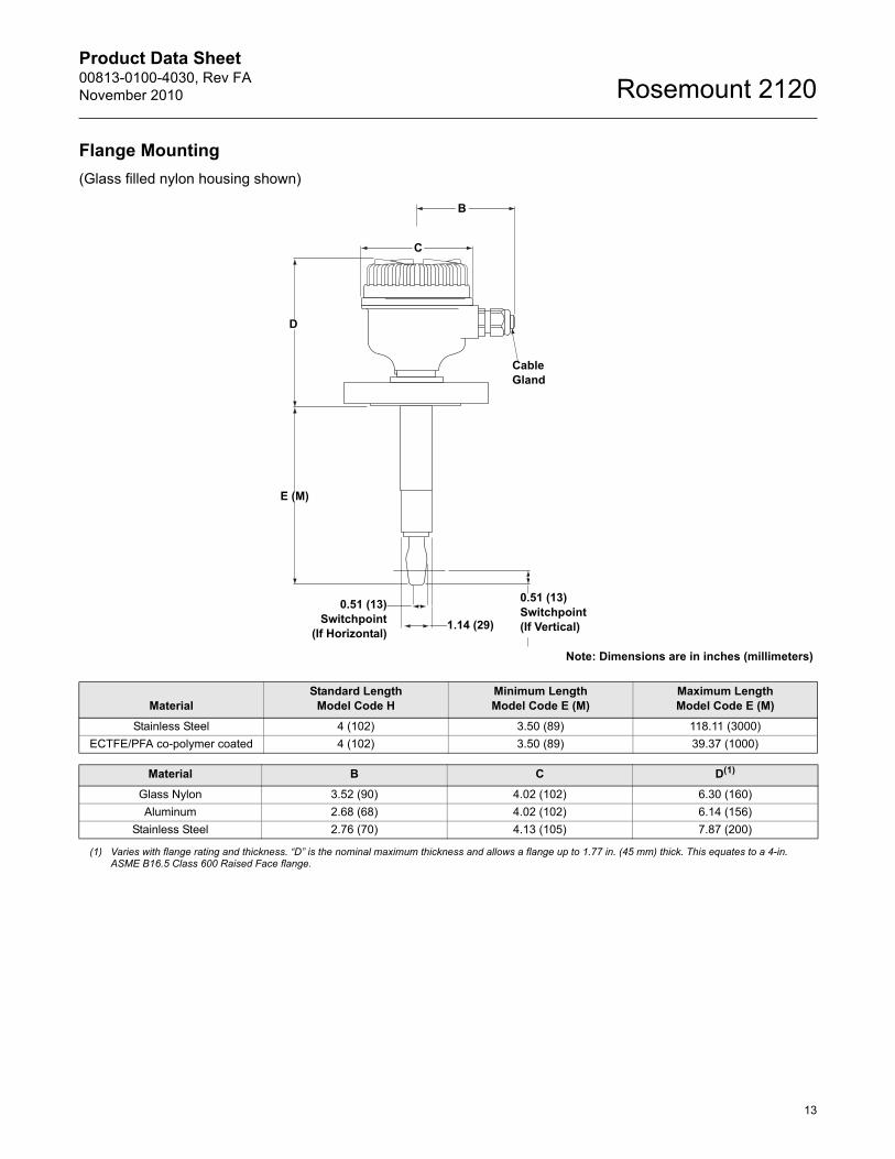
Flange Mounting
(Glass filled nylon housing shown)
Note: Dimensions are in inches (millimeters)
D
1.14 (29)
B
C
Cable Gland
E (M)
0.51 (13)Switchpoint
(If Horizontal)
0.51 (13)Switchpoint (If Vertical)
MaterialStandard Length
Model Code HMinimum Length Model Code E (M)
Maximum LengthModel Code E (M)
Stainless Steel 4 (102) 3.50 (89) 118.11 (3000)
ECTFE/PFA co-polymer coated 4 (102) 3.50 (89) 39.37 (1000)
Material B C D(1)
Glass Nylon 3.52 (90) 4.02 (102) 6.30 (160)
Aluminum 2.68 (68) 4.02 (102) 6.14 (156)
Stainless Steel 2.76 (70) 4.13 (105) 7.87 (200)
(1) Varies with flange rating and thickness. “D” is the nominal maximum thickness and allows a flange up to 1.77 in. (45 mm) thick. This equates to a 4-in. ASME B16.5 Class 600 Raised Face flange.
Product Data Sheet00813-0100-4030, Rev FA
November 2010Rosemount 2120
14
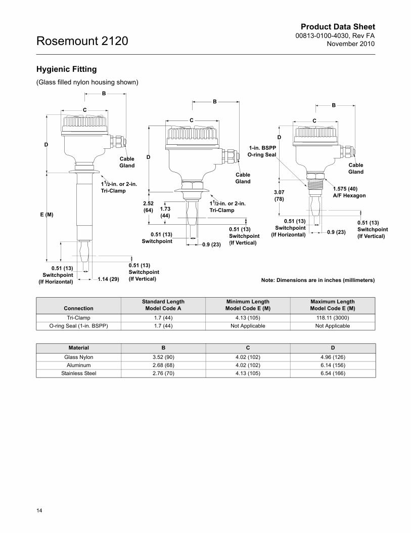
Hygienic Fitting
(Glass filled nylon housing shown)
Note: Dimensions are in inches (millimeters)1.14 (29)
Cable Gland
Cable Gland
0.9 (23)
D
D
2.52(64) 1.73
(44)
C
C
B
B
E (M)
0.51 (13)Switchpoint (If Vertical)
0.51 (13)Switchpoint (If Vertical)
B
C
D
Cable Gland
1.575 (40) A/F Hexagon
0.51 (13)Switchpoint (If Vertical)
3.07(78)
0.9 (23)
0.51 (13)Switchpoint
0.51 (13)Switchpoint
(If Horizontal)
0.51 (13)Switchpoint
(If Horizontal)
11/2-in. or 2-in. Tri-Clamp
11/2-in. or 2-in. Tri-Clamp
1-in. BSPPO-ring Seal
ConnectionStandard Length
Model Code AMinimum Length Model Code E (M)
Maximum Length Model Code E (M)
Tri-Clamp 1.7 (44) 4.13 (105) 118.11 (3000)
O-ring Seal (1-in. BSPP) 1.7 (44) Not Applicable Not Applicable
Material B C D
Glass Nylon 3.52 (90) 4.02 (102) 4.96 (126)
Aluminum 2.68 (68) 4.02 (102) 6.14 (156)
Stainless Steel 2.76 (70) 4.13 (105) 6.54 (166)
Product Data Sheet00813-0100-4030, Rev FANovember 2010
15
Rosemount 2120
Product Data Sheet00813-0100-4030, Rev FA
November 2010Rosemount 2120
The Emerson logo is a trademark and service mark of Emerson Electric Co.Rosemount and the Rosemount logotype are registered trademarks of Rosemount Inc.All other marks are the property of their respective owners.Standard Terms and Conditions of Sale can be found at www.rosemount.com\terms_of_sale
00813-0100-4030 Rev FA 11/10
© 2010 Rosemount, Inc. All rights reserved.
Rosemount Level Solutions
Emerson provides a complete range of Rosemount products for level measurement applications.
Vibrating Fork Switches – Point Level Detection
For high and low alarms, overfill protection, pump control, including wide pressure and temperature requirements, and hygienic applications. Flexible mounting. Immune to changing process conditions and suitable for most liquids.The product line consists of:
• Rosemount 2160 Wireless
• Rosemount 2130 Enhanced
• Rosemount 2120 Full-featured
• Rosemount 2110 Compact
Differential Pressure – Level or Interface Measurement
Flexible mounting for liquid tank levels, including those with wide temperature and pressure requirements. Can be isolated by valves. Unaffected by: vapor space changes, surface conditions, foam, corrosive fluids, internal tank equipment. Optimize performance with direct mount, Tuned-System Assemblies:
• Rosemount DP Level Transmitters and Remote Seals
• Rosemount 3051S_L, 3051L, and 2051L Liquid Level Transmitters
Ultrasonic – Level Measurement
Top mounted, non-contacting for simple tank and open air level measurements. Unaffected by fluid properties such as: density, viscosity, dirty coating, and corrosiveness. Appropriate for routine applications outside of explosion proof areas.The product line consists of:
• Rosemount 3100 Series Ultrasonic Process Level Transmitters
Guided Wave Radar – Level and Interface Measurement
Top mounted, direct level and interface measurement of liquids or solids, including those with wide temperature and pressure requirements. Unaffected by changing process conditions. Good fit for small spaces and easy swap for older technologies.The product line consists of:
• Rosemount 5300 Series – Accurate, superior performance transmitter in most applications including process vessels and control
• Rosemount 3300 Series – Versatile and easy-to-use transmitter in most liquid storage and monitoring applications
Non-contacting Radar – Level Measurement
Top mounted, direct level measurement for liquids or solids, including those with wide temperature and pressure requirements. Can be isolated by valves. Unaffected by changing process conditions. Good for dirty, coating, and corrosive applications.The product line consists of:
• Rosemount 5400 Series – Accurate, superior performance 2-wire transmitters for most liquid level applications and process conditions
• Rosemount 5600 Series – 4-wire transmitters with maximum sensitivity and performance for solids, challenging reactors, rapid level changes, and excessive process conditions
Chambers for Process Level Instrumentation
• Rosemount 9901 – High quality chambers for external mounting of level measurement and control instrumentation on process vessels
Emerson Process Management Rosemount Measurement8200 Market BoulevardChanhassen, MN 55317 USATel (USA) 1 800 999 9307Tel (International) +1 952 906 8888Fax +1 952 949 7001www.rosemount.com
Emerson Process ManagementBlegistrasse 23P.O. Box 1046CH 6341 BaarSwitzerlandTel +41 (0) 41 768 6111Fax +41 (0) 41 768 6300
Emerson Process ManagementAsia Pacific Pte Ltd1 Pandan CrescentSingapore 128461Tel +65 6777 8211Fax +65 6777 0947Service Support Hotline: +65 6770 8711Email: [email protected]
Emerson FZEP.O. Box 17033Jebel Ali Free ZoneDubai UAETel +971 4 811 8100Fax +971 4 886 5465