Roof Framing Made Easy 1903
175
Transcript of Roof Framing Made Easy 1903

7/25/2019 Roof Framing Made Easy 1903
http://slidepdf.com/reader/full/roof-framing-made-easy-1903 1/174

7/25/2019 Roof Framing Made Easy 1903
http://slidepdf.com/reader/full/roof-framing-made-easy-1903 2/174
JOHN
GALEN
HOWARD
7/25/2019 Roof Framing Made Easy 1903
http://slidepdf.com/reader/full/roof-framing-made-easy-1903 3/174

7/25/2019 Roof Framing Made Easy 1903
http://slidepdf.com/reader/full/roof-framing-made-easy-1903 4/174
*** ''
>
-
K.
;
7/25/2019 Roof Framing Made Easy 1903
http://slidepdf.com/reader/full/roof-framing-made-easy-1903 5/174
ROOF
FRAMING
MADE
EASY
A PRACTICAL
AND
EASILY
COMPREHENDED
SYSTEM,
ADAPTED
TO
MODERN
CONSTRUCTION,
FOR
LAYING
OUT
AND
FRAMING- ROOFS
THE
METHODS
ARE MADE
CLEAR AND
INTELLIGIBLE
BY
NEARLY 100
ENGRAVINGS
WITH
EXTENSIl'E EXPLANATORY
TEXT
BY
OWEN
B.
MAGINNIS,
ARCHITECT
INSPECTOR
OF
BUILDINGS
OF THE
CITY
OF
NEW YORK
Author
of
How
to
Frame
a
House.
How
to Measure
up
Woodwork
for
Buildings,
Bricklaying,
etc..
etc.
Second
Edition,
Revised
and
Greatly
Enlarged
X
E
W
YORK
THE
INDUSTRIAL PUBLICATION
COMPANY
1
903
7/25/2019 Roof Framing Made Easy 1903
http://slidepdf.com/reader/full/roof-framing-made-easy-1903 6/174
77/
Copyright
secured
1896
and
1903
BY
OWEN
B.
MAGINNIS

7/25/2019 Roof Framing Made Easy 1903
http://slidepdf.com/reader/full/roof-framing-made-easy-1903 7/174
CONTENTS.
Chapter
I.
The
Principle
of
the
Roof
and
General
Directions
9
Chapter
II.
Laying
Out and
Framing
a
Sim-
ple
Roof.
13
Chapter
III.
Hip
and
Valley
Roofs
16
Chapter
IV.
Roofs
of
Irregular
Plan
24
Chapter
V.
Square
Pyramidal
Roofs
28
Chapter
VI. To Frame a
Pentagonal
Roof.
.
.32
Chapter
VII.
Hexagonal
Pyramidal
Roofs.
. .
.36
Chapter
VIII.
Conical
Roofs
40
Chapter
IX.
To
Frame
a
Conical
Roof Inter-
sected
by
a
Pitched
Roof..
.
.
.45
Chapter
X.
Octagonal
Roofs
48
Chapter
XI.
Framing
an
Octagonal
Roof
of
Gothic
Style
50
Chapter
XII.
Framing
an
Octagonal
Molded
Roof
54
Chapter
XIII.
Framing
an
Octagonal
Roof
with
Circular
Dome
*.....
59
Chapter
XIV.
To
Frame
a
High-Pitched
or
Church
Roof
63
Chapter
XV.
To Frame
a
Mansard
Roof 66
Chapter
XVI.
Hemispherical
Domes
71
Chapter
XVII.
To Frame
a
Circular
Elliptic
Dome
75
S21188

7/25/2019 Roof Framing Made Easy 1903
http://slidepdf.com/reader/full/roof-framing-made-easy-1903 8/174
6
CONTENTS.
Chapter-XVIII.
To
Frame
an
Elliptic
Dome with
an
Elliptic
Plan
80
Chapter
XIX.
To
Frame
a Circular Molded
Roof.
85
Chapter
XX.
To Frame
a
Gothic
Square
Roof
of
4
Centre
Section
91
Chapter
XXI.
To Frame
a
Trussed
Roof
of
Moderate
Span
on
the
Bal-
loon
Principle
95
Chapter
XXII.
To Frame
a
Roof
of
Unequal
Heights
of
Pitches
and
Plates
.
99
Chapter
XXIII.
To Frame
a
Hip
and
Valley
Roof
of
Unequal
Pitch
103
Chapter
XXIV. To
Frame
a
Roof
of
Unequal
Lengths
of
Rafters
107
Chapter
XXV.
To
Frame
a
Roof
with
Pitched
Ridges
1
10
Chapter
XXVI.
To
Frame
a
Round
-
House
Roof.
1
14
Chapter
XXVII.
Framing
Cantilever Roofs.
. .
.
1
16
Chapter
XX
VI
II.
To
Frame
a
Roof
with
an
Ellip-
tic
Plan and
Straight Ridge.
.122
Chapter
XXIX.
Church
Roof
Construction
129
Chapter
XXX.
Bow
Truss
Roofs
141
Chapter
XXXL Roofs for
Studios
147
Chapter*
XXXII.
How
to
Build
a
Circular
Framed
Tower
with
a
Molded
Roof.
.
149
Chapter
XXXIIL
Details and
Suggestions
159

7/25/2019 Roof Framing Made Easy 1903
http://slidepdf.com/reader/full/roof-framing-made-easy-1903 9/174
PREFACE.
In
placing
this,
the
second
Edition
of
this
little
work
before
the student
of Architecture
or
Building
construction
I
would
state
that
the
rapid
sale which
the
previous
edition
has
had,
warrants
the
assumption
that
this
will
also
be
appreciated
by
those
who
are
desirous
of
becoming
proficient
in
the
higher
branches,
and
who
wish to
apply
the
best
and
simplest
methods
in
prac-
tice.
With
the
assurance to
the
student
that
the
con-
tents,
if
studied,
will
return
him full remuneration
by
his
becoming
more
valuable
on
account
of
his
increased
knowledge
;
I
send it
forth
confidently.
The
articles
were
originally
published
in
Carpentry
and
Building
and
l(
The
Carpenter
and are
now re-
published,
by permission,
edited
and revised.
The
entire
vvork
is
dedicated to
my
Wife,
through
whose
aid
and
encouragement
I have
been
enabled to
persevere
and
succeed
in
the
study
of
technical
principles.
The Author.
New York
City,
1903.
42V

7/25/2019 Roof Framing Made Easy 1903
http://slidepdf.com/reader/full/roof-framing-made-easy-1903 10/174
7/25/2019 Roof Framing Made Easy 1903
http://slidepdf.com/reader/full/roof-framing-made-easy-1903 11/174
ROOF
FRAMING
MADE
EASY.
CHAPTER
I.
The
Principle
of
the
Roof
and
General Directions.
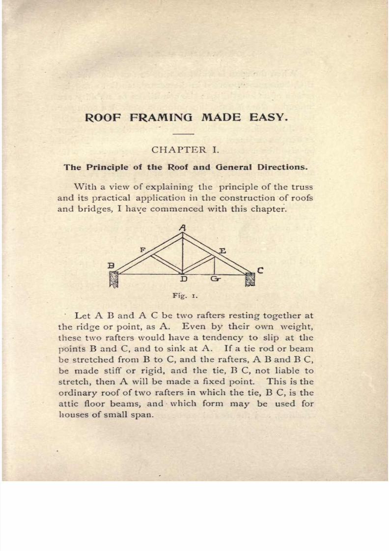
With
a
view
of
explaining
the
principle
of
the
truss
and its
practical
application
in the
construction
of
roofs
and
bridges,
I
have commenced
with this
chapter.
Fig.
i.
Let
A
B
and
A
C
be
two
rafters
resting
together
at
the
ridge
or
point,
as
A.
Even
by
their
own
weight,
these
two rafters
would
have
a
tendency
to
slip
at
the
points
B
and
C,
and to sink
at
A. If
a
tie
rod
or
beam
be
stretched
from
B
to
C,
and the
rafters,
A
B
and
B
C,
be
made
stiff
or
rigid,
and the
tie,
B
C,
not
liable
to
stretch,
then
A
will
be
made
a
fixed
point.
This is the
ordinary
roof
of
two
rafters
in
which
the
tie,
B
C,
is
the
attic
floor
beams,
and
which
form
may
be used
for
houses
of
small
span.

7/25/2019 Roof Framing Made Easy 1903
http://slidepdf.com/reader/full/roof-framing-made-easy-1903 12/174
10
ROOF
FRAMING
MADE EASY.
When
the
span
is
wide,
so
wide
in
fact
that the
tie,
B
C,
being
unsupported
in
the
centre,
tends
to
sag by
reason
of
its
length,
then the conditions
of
stability
are
injured.
Now
if from
the
point
or
peak
A a
string
or
tie
be
let down and
attached
to
the
middle
of
B
C,
as
D,
it
will
then be
impossible
for B
C
to
bend
or
sag
down,
as
long
as
A B
and B
C are
the
same
length.
D will
be
also
like
a
stationary point
if
the
suspension
or
tie
A
D
be
of
iron
or
wood
and
not stretch.
But
the
span
may
be
increased,
or
the size
of
the rafters
A B
and
A
C
diminished
until the
rafters
tend
to
sag,
and
to
prevent
this,
struts,
as D
E and
D
F,
are set
in,
reaching
from
the
stationary
point
D to
the
middle
of
each
rafter,
or
to
the
centre of
its
length,
as
E and
F
;
thus
making
E
and
F
stationary points, provided
the
struts
E
D
and
F
D
remain
their
full
length.
By
this
means
they
truss
or
tie
up,
the
point
D,
and
the
frame,
A B D
C,
is
a
trussed
frame,
or
in
the
term
applied
in
carpentry,
a
truss.
Similarly,
if
D
C
be
long
its
centre
can
be
suspended
from
the
fixed
point
E
by
a
suspension
rod,
as
E
G.
In
every
truss there are
two
principal
strains exerted
on the
members.
These
are
termed
Compression
and
Tension.
For
this
simple
truss the
rafters
A
B and
A
C
are
in
Compression,
or
being
pushed
together.
A
D
and
B
C
are
extended,
or
in
Tension.
Those
which are
in
tension can either be made
of
wood
(as
wood
is
not:
liable
to
stretch)
or
of
wrought
iron
rods,
but
never
of
ropes,
or
any
material
likely
to
stretch
easily.
From
the
above,
the
student
will
understand that
:
the
rafters,
by
their
not
being
subject
to
compression
or
crushing,
and the
tie rod
or
beam,
not
being
liable
to

7/25/2019 Roof Framing Made Easy 1903
http://slidepdf.com/reader/full/roof-framing-made-easy-1903 13/174
ROOF
FRAMING
MADE
EASY.
11
stretch,
or,
in
better
words,
subject
to
tension,
and
the
suspension
rod
complete
the
truss,
thus
preventing
the
sagging
of
the centre
of
the
tie
beam.
In
modern
roof
construction,
engineers,
as
a
rule,
use timber
for rafters
and
struts
and
iron
for
tie
and
suspension
rods
;
these materials
being
light
and
easily
put
together
;
and
I am
sure
many
readers
will
meet
roofs
of
this
class.
Fig.
2.
In
the
ordinary
form
of house
roof
shown
at
Fig.
2,
the
rafters
are
in
compression,
the
ties,
or
attic
floor
beams,
in
tension,
and the
collar
beam
is
in
compres-
sion,
as
it
takes
the
place
of the
struts,
yet
gives
the
head
room.
GENERAL
DIRECTIONS.
Roofs
should
be laid
out to
a
scale on
a
large
sheet
of
detail
paper
or on
a
drawing-board,
using
a
lead
pen-
cil and
two-foot
rule
or
steel
square.
The
writer
gen-
erally
uses
either
3
inch
or
\
l
/
inch
scale;
if
possible,
as it
sometimes is
on
small
work,
full size.
The
reason
these
are the
best
working
scales
is
be-
cause
the
three
inch scale
works
as
follows
:

7/25/2019 Roof Framing Made Easy 1903
http://slidepdf.com/reader/full/roof-framing-made-easy-1903 14/174
12
ROOF
FRAMING MADE
EASY.
3
inches
=
I
foot
%
inch
=
I
inch
\y
=6
inches
%
=
}/
i
=
4
'
A
=
ti
%
=2
A
=
%
The
one
and
a
half
\nc\\ scale
is
similar
but the
di-
visions
are not
so
handy.
For
instance
:
\y
inches
=
I
foot
*/
inch
=
i
inch
tf
=
6
inches
&
=
^
*/
=4
''
A
=
%
X
=2
'
The
above
two scales
are
the usual
working
scales
with
the
exception
of
the
half
size
proportion
which
is
very simple
and
easily
applied
thus :
6
inches
=
i
foot
J^
inch
=
I inch
5
=10
inches
^
=
y
4
=
8
J/Q
=
i<
3
=
6
.i
=
%
.
.1
-
_
16
.1
-
J_
32
The
foregoing
scales are the best
for
mechanics,
either foremen
or
at
the works.
The full
size
laying
out
is best
when
possible.
Whether the
work
is
laid
out to
scale
or
full
size,
the exact
measurements
should
always
be marked
in
plain figures
on
every
piece.
The
figures
on
the
steel
square
for
marking
cuts
may
be
used
if
desired,
by
placing
the
square
on
the scale
drawing
and
noting
the
figures
on
the
blade
and
tongue.

7/25/2019 Roof Framing Made Easy 1903
http://slidepdf.com/reader/full/roof-framing-made-easy-1903 15/174
ROOF
FRAMING
MADE EASY. 18
CHAPTER
II.
Laying
out
and
Framing
a
Simple
Roof.
Let
A
B
C
D
Fig.
3,
be
the
plan
of
the
wall
plates.
A
D
a
gabled
end,
and
B
C
a
hipped
end
of
the build-
ing.
The
roof
is
1
2
feet
wide
to
the
outside
faces of
Fig.
4.
PLAN
AND
LAYOUT
OF A
SIMPLE
ROOF.
the
wall,
and
the
rise
or
pitch
4
feet
or one-third the
span.
The dotted lines denote
centre
lines.
To
lay
out
the gable
end
produce
the center
line
of
the
ridge
E
I
F
to
G
and
from
F
measure
up
4
feet,
join
G
A
and
G
D.
Now
set
off
on each side
of
the
dotted

7/25/2019 Roof Framing Made Easy 1903
http://slidepdf.com/reader/full/roof-framing-made-easy-1903 16/174
14
ROOF FRAMING
MADE
EASY.
t
H
fg-o-
Fig
3.
Pi
AN
OF
RAFTERS.

7/25/2019 Roof Framing Made Easy 1903
http://slidepdf.com/reader/full/roof-framing-made-easy-1903 17/174
ROOF
FRAMING
MADE
EASY.
15
line
shown,
the width
of
the
rafter
2
inches
on
each
side
for
a
4
inch
rafter,
and
3
inches
on each side
for
a
6
inch
rafter
as shown on
the
top
of
Fig.
3,
deduct
half
the
thickness of the
ridge,
half
inch,
from each rafter
peak,
cut
also
notch
out
for the
cut
on
the
plate.
All
the rafters
from
F
to
E
will
be
framed
thus :
For
the
hip
rafters,
take
the distance
B
C
and
trans-
fer
it
to
J
K,
Fig.
4,
divide
it
into
two
parts
6
feet at
L,
and
square
up
as
L
M
O.
Join
M
J and
M
K.
Pro-
duce
J
M to
N,
and
join
N K.
N
K,
will
be
the
centre
line
length
of
the
hip,
and the width
may
now
be set
oft
on
each side
of it
in
the manner shown
in
the
diagram.
With
K
as
centre
and K N
as
radius,
strike
the arc
N
O,
cutting
L M
extended
in
O. On
L
K
lay
off
the
jack
rafters
as
Q
P
S
R,
etc.
;
equally
spaced
and
square
to
the
wall
plate.
The
exact
lengths of
the
jacks
will
be to the
line
O
P
R
K,
and their
side
bevel
will be
as
at P.
The bottom notch
will
of
course be
as
at
A
or
D
;
K
shows the
bottom
notch
for
the
hip
rafters
and
N
the
peak
cut
or
plumb
cut. Great
care
should
be
taken to have
the lines
as
accurate
as
possible,
so
that
the measurements
will
be
exact.
7/25/2019 Roof Framing Made Easy 1903
http://slidepdf.com/reader/full/roof-framing-made-easy-1903 18/174
16
ROOF FRAMING MADE
EASY.
CHAPTER III.
Hip
and
Valley
Roofs.
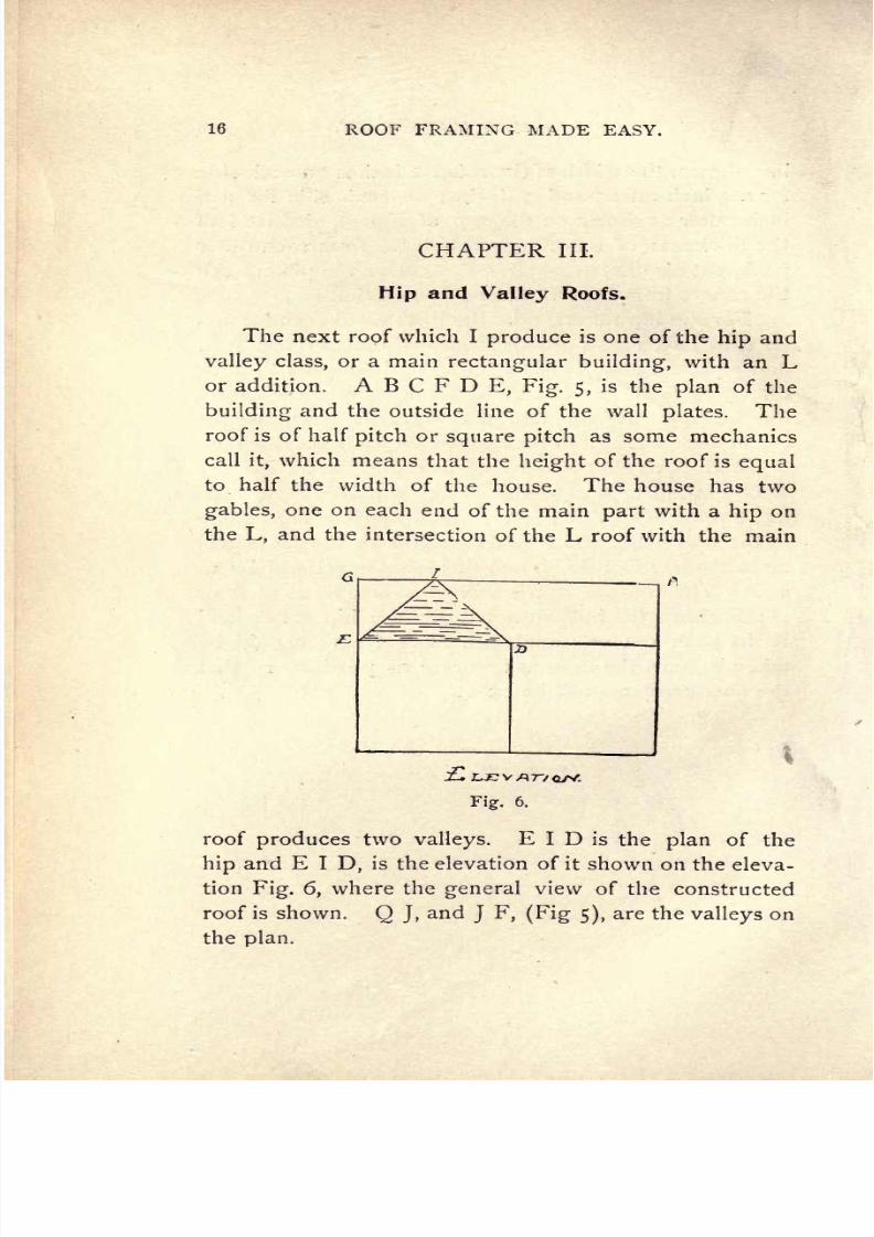
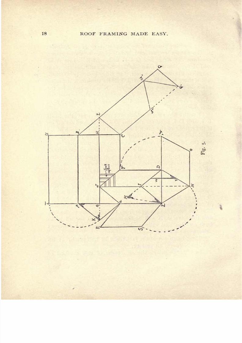
The
next roof which
I
produce
is
one
of
the
hip
and
valley
class,
or a main
rectangular
building,
with
an
L
or
addition. A
B
C
F D
E,
Fig.
5,
is
the
plan
of
the
building
and
the
outside
line
of
the
wall
plates.
The
roof
is
of
half
pitch
or
square
pitch
as some
mechanics
call
it,
which
means
that the
height
of
the roof
is
equal
to
half
the
width of
the
house.
The
house
has
two
gables,
one
on
each
end of
the
main
part
with
a
hip
on
the
L,
and
the
intersection
of
the
L
roof
with
the
main
Fig.
6.
roof
produces
two
valleys.
E
I
D
is
the
plan
of
the
hip
and
E I
D,
is
the
elevation
of
it
shown
on
the
eleva-
tion
Fig.
6,
where
the
general
view
of
the
constructed
roof
is
shown.
Q
J,
and
J
F,
(Fig
5),
are
the
valleys
on
the
plan.

7/25/2019 Roof Framing Made Easy 1903
http://slidepdf.com/reader/full/roof-framing-made-easy-1903 19/174
ROOF
FRAMING
MADE
EASY. 17
In
framing
this roof
the
simplest
way
is
as follows:
To
obtain
lengths
and
bevels of
the
common
rafter,
produce
the
ridge
line
G
J
H
to
L and
K.
Join
A
K,
and
K
Q
;
also
B
L,
and L
C.
A
K,
will
be
the
neat
length
of
the
common
rafter,
if
no
ridge
board
is
inserted;
but
if
there
be a
ridge
board,
half
its
thickness
must
be
sawn
off
the
length
on
the
bevel. K
is
the
bevel
for
the
top
or
peak
cut
and
A,
the bevel for
the
cut
on
the
plate.
Any
ordinary
mind will
see
the
simplicity
of
this
method.
For
the
hip
rafters
which will
stand
over
the seats
E
I,
and
D
I,
produce
the
line
D
I,
to
M,
and
set
off on
it
the
height
of
the
pitch
I
M,
equal
to
K
G.
Join
M
E
;
M
E will
be
the
exact
length
of
the
hip
rafter
required,
and
the bevel
at
M
will
fit
the
top
cut,
and
that
at
E
the
plate
cut.
In
regard
to
the
cuts
for
the
jack
rafters,
which
run
up
the
hips
and
valleys,
it
might
be
said
that
the
top
cuts
against
the
ridges
for
the
rafters
which
run
up
the
valleys
have
the
top
cut
the
same
as
the
common
rafter
top
cut.
The
bottom
one
which
nails
against
it,
can be
readily
determined
by
the
following
simple
method :
Produce
the
ridge
line
J
I,
to
N,
and make
D
N,
and
N
E,
equal
to
M
E,
the
length of the
hip.
W
is
the
jack
on its
seat
or
as
it
will
appear
in
position.
X
is
the
exact
length
of
it
from
the
plate
line
to
the
hip,
and
the
bevel at
X
will be
the
exact
bevel for
all
jacks
both on
hips
and
valleys
;
being
reversed
for
different
sides,
right
and
left hand.
The
plumb
cut of
the
jacks
will
be half
pitch,
'or
on
the
steel
square,
12
and
12.
In
order
to
prove
the
exactness
of
this
method of
7/25/2019 Roof Framing Made Easy 1903
http://slidepdf.com/reader/full/roof-framing-made-easy-1903 20/174
18
ROOF
FRAMING
MADE
EASY.

7/25/2019 Roof Framing Made Easy 1903
http://slidepdf.com/reader/full/roof-framing-made-easy-1903 21/174
ROOF FRAMING
MADE
EASY.
19
laying
out
such
a
roof,
we will
proceed
to
develop
its
planes
or
sides.
As
to
the
rectangular
plane,
A
B
G
H,
take
a
pair
of
compasses
with
a
pencil
point,
and
with
A,
as
centre,
and
with
A
K,
as a
radius,
describe
the
arc
K
I
;
draw
T
U,
parallel
to
A
B,
produce
G
A,
to
T,
and
H
B
to
U,
this
will
give
ABUT,
the
exact
covering
of
A
G
H
B,
on
the
pitch
A K
;
A
K,
being
the
length
of
the
com-
mon
rafter
with
its
necessary
bevels.
For
the
plane
J
H
C
F,
produce
B L to
G',
and draw
C
F
Q parallel
to
B
L
J
G
7
.
Make L
J
G'
equal
to
H
J
G,
C
F
equal
to
C,
F,
also
F
7
,
Q', equal
to
Q,
F,
make
J,
F,
and
J,
Q,
on
the
right,
equal
to
M,
E,
which will
complete
the
plane
and
surface
to cover
G
J
H
C,
F
Q
on
the
plan.
For
the
plane
J
F
D
I,
take
D
as centre,
and
with
D
F
as
a
radius
describe the
quarter
circle
F
P. Produce
ED,
to
P,
and
through
P
draw
P
O,
parallel
to
D
N,
also
through
N
draw
N
O,
parallel
to
D
P.
D
N
O
P,
will be
the
developed
covering,
and
Q
R
S
E
is
simi-
larly
found.
B
L
C
and
A
K
Q
are the
gables.
Now
if
this
roof
be
laid
out
on
a
piece
ol
thin
wood
or
stiff
Bristol
board the
roof
can be
folded
over
by
cut-
ting
entirely
through
the
following
lines :
Cut
from
K
to
A,
A
to
I,
I
to
U,
U
to
B,
B
to
L,
L
toG',
Q'
to
J',
J'
to
F',
F
to
C,
C to
F,
F
to
D,
D
to
P,
P
to
O,
O to
N,
N
to
E,
E
to
S,
S to
R,
and
R
to
Q.
Also
make a
slit
half
way
through
the thickness
of
the
board,
from
Q
to
A,
A
to
B,
B
to
C,
C to
L,
D
to
N,
D
to
E,
and E
to
Q.
By
folding
the
sides or
planes
over,
the
exact roof

7/25/2019 Roof Framing Made Easy 1903
http://slidepdf.com/reader/full/roof-framing-made-easy-1903 22/174
20
ROOF
FRAMING
MADE
EASY.
will
be
seen,
thereby
proving
the correctness
of
the
method.
The
many
apparently
complex
roofs
which are now-
adays
placed
on
frame
buildings
are
apt
to
discourage
those
young
mechanics who
are
ambitious,
so
in
order
to
simplify
and
bring
them within the
grasp
of
all
I
have
now
adopted
a
plan
of
roof
of
somewhat unusual
form.
At
Fig.
7
the
plan
isABCDEFGHIJLand
K,
being
the
plan
of
a
small
frame house
costing
about
$2,000.
Fig.
8
is an
end view
or
gable
elevation show-
ing
the
pitch
of
the
common
rafters
which we will
as-
T
KB
Fig.
8.
PROJECTION
OF
ROOF.
sume to
be
full
pitch,
or
12
inches rise
and 12
inches
run
on the steel
square.
A
B
is
the
top
line
of
the
plate
across the
bay,
or
across
the
widest
part
of
the
house.
A
K
is
the
span
across
the
main walls and
E
J
the
rise
or
pitch
;
therefore
A
J
will
be
the
length
of
the com-
mon
rafters
on
the
plan Fig.
7,
that
will be
set
on
the
plate
A
K
from
N
to
O
on
the
ridge.
A
G,
Fig.
8,
is
the
span
across,
the
narrowest
part
of
the
house
or
from
A
to
B,
Fig.
7,
and
E M
is
the
rise or
pitch,
conse-

7/25/2019 Roof Framing Made Easy 1903
http://slidepdf.com/reader/full/roof-framing-made-easy-1903 23/174
ROOF
FRAMING
MADE
EASY.
21
K
Fig.
7.
PLAN
AND
LAYOUT
OF
ROOF.

7/25/2019 Roof Framing Made Easy 1903
http://slidepdf.com/reader/full/roof-framing-made-easy-1903 24/174
22
ROOF
FRAMING
MADE
EASY.
quently
A
M
will
be
the
length
of
the
short
common
rafters
and the bevels will
be
as
represented
at
J
M
and
A.
Now
to
find
the
lengths
of
the
hips
and
valleys
and
bay
window
rafters,
refer
to
Fig.
7,
and
commencing
at
the
near
valley
C
M
square
up
the
line
M
R,
make it
equal
to
E
M on
Fig.
7
and
join
C
R.
C
R will
be
the
length of
the valley
with
top
and
bottom
bevels
as
shown.
On
the
seat
of
the
hips
N
D,
square
up
the
rise
N
T
equal
to
E
J,
Fig.
7,
and
join
D T for
length
of
hip,
with
top
and
plate
bevels
as
at
D
and
T.
It
will
be noticed
that these
rafters
are
parallel
on
the
lay-out
because their seats
are
parallel,
therefore
they
must
be correct
;
the
valley
rafter
L
Q
to stand
over
L
P is
determined
in like manner
also
the
hip
S
K
to
stand
over
O
K.
As
I have
previously
shown
several
ways
to
obtain
the
lengths
of
jack
rafters
on
half
pitch
roofs
I
will not
repeat
this
simple
method here
but
go
on
and
give
lay-
out
of
bay
window
timbers.
Referring
again
to
the
engraving
Fig.
8
we
find
that
the
plate
line
of
the
bay
C
H D
is
higher
or raised
up
4
feet above the level
of
the
plate
line
of the
principal
or
main walls
as
A
G
B
;
to
find-
lengths
of rafters
we
go
back
again
to
Fig. 7.
Here
on the seat
of
the
hip
E
U
we
proceed
to
square
up
the
rise UV
and
join
E
V,
which
will
be
the
length
of
the
hip
U
V,
being
equal
to
the
rise
C
J,
Fig.
8.
There
will be four
hips
this
length
to stand
over E
U,
F
U,
G
U,
and
H
U,
on
the seat
of
the
W
X.
Square up
the
rise
X
Y
and
join
W
Y
for
length
of
valley.
There
will
be
two
needed,
one
for
each
side.
Jacks
can be found
as
before
described.

7/25/2019 Roof Framing Made Easy 1903
http://slidepdf.com/reader/full/roof-framing-made-easy-1903 25/174
ROOF
FRAMING
MADE
EASY.
23
Regarding
the
jack
rafters
reaching
from
the
valleys
over
W
X
to
the
hips
D N and
O
P I
might
state that
the
bottom
and
top
cuts
will
be
alike
up
to
the
points
N
and
O
where
the
hips
join
the
ridge
N
O.
Against
it
they
will
be
a
square
cut
on
top
edge
with
the down
cut
as
at
J
Fig.
7.
When
calculating
the timbers
or
laying
out
roofs of
this
description,
too
much
care cannot be
bestowed
in
finding
the
exact
number
of
rafters
required,
the
right
and left hand
cuts
of the
bevels on
the
jacks,
etc.,
and
the
exactness
of.
framing
to
the
neat
lengths required
so
as
to
prevent
mistakes
or
recutting.

7/25/2019 Roof Framing Made Easy 1903
http://slidepdf.com/reader/full/roof-framing-made-easy-1903 26/174
34
ROOF
FRAMING
MADE
EASY.
CHAPTER IV.
Roofs
of
Irregular
Plan.
This
chapter
embraces
a
roof
of another
and rather
uncommon
plan,
and
one
which
will be
interesting
to
work
out.
It
is
a
form
of
roof
which
sometimes
occurs
and
will
prove
useful.
A B
C
D,
Fig.
9,
is the
plan,
and
it
will
be
noticed
that
the
side walls are
not
parallel,
or
at
equal
distance
apart
from
end to
end,
but
spread
or
widen out
from
A
to
B,
and
from
C
to
D,
or
B
D is
longer
than
A
C.
Similarly
A
B,
is
longer
than
C
D,
and
not
parallel
to
C
D.
For
this reason
coupled
with
the
necessity
of
keeping
the
ridge
level on both
sides
a
deck
is
formed
on
the
top,
or
more
properly
two
ridges
are
needed,
one
for
each
side,
and
parallel
to
each
wall
plate
;
these
are
shown at
E
F
and E
G.
The
seats
of
the
hips
as
A
E,
C
E,
B F and
D
G,
are
found
by
bisecting each
of the
separate angles
on
the
plan,
which
can
be done
by taking
any
two
points
equidistant
from the
apex
of
the
angle
as
A,
and
strik-
ing intersecting
arcs.
(As
every
student
knows
how to
do
this
I will
not
illustrate
it
here.)
This
process
will
give
the
seats
of
the
hips
as shown
and
lettered,
with
the
addition
of a
short
piece
of
ridge
F
G.
To
find
the
lengths
and
bevels
of
the
rafters,
pro-
ceed
as
follows :
For the common
rafters
to
range
from
U
E,
t6
V
F,
on
the
one
side,
and
from
E
W,
to G
X,

7/25/2019 Roof Framing Made Easy 1903
http://slidepdf.com/reader/full/roof-framing-made-easy-1903 27/174
ROOF
FRAMING
MADE
EASY.
25
\

7/25/2019 Roof Framing Made Easy 1903
http://slidepdf.com/reader/full/roof-framing-made-easy-1903 28/174
26
ROOF
FRAMING
MADE
EASY.
on
the
other
side;
raise
up
the
pitch
G
P.
Square
out
from
G
to
X,
and
join
P X
which
joining
line
will
be
the
exact
length
of
the
common
rafter from
outer
edge
of
plate
to
centre line
of
ridge.
To
obtain
length
of
hip
rafters
square
up
from
each
point
at the
peaks,
as
E H
;
F
I,
on
one side.
Make
E
H,
and
F
I
each
equal
to
G
P,
A
H,
and
B I
will be
the
lengths
of
the
hip
rafters,
which
will
rise over
A
E
and
B
F. The
hip
rafters
which
will
be set
up
over the
seats,
C
E,
and
D
G,
are
determined in
a
similar
manner. The
top
and
bottom
bevels
delineated
at the
peaks
and
bottoms
are
the
top
and
bottom
cuts
of
each,
and
it
will be
noticed
that
no
two
bevels
are
alike,
so
that each
rafter
must be
care-
fully
laid
out
and
marked for
each
particular
corner.
There will
be four
hips
of
different
lengths
and
with
dif-
ferent
bevels,
so
they
must
be
properly
framed.
In
re-
gard
to
the
jack
rafters
they
are shown on
the
right
side
spaced
out
on
the
wall
plate
from
X
to
D,
against
the
hip,
G D. Their
top
down
bevel or
plumb
cut will
be
the
same
as
that at
P,
that
at
R
will
be
the
side bevel.
Similarly
with
those
from
D
to
M,
the
plumb
cut
will
be
the
same as
P,
but
the
bevel
will
be that
at
O.
In
order to
develop
the
planes
of
this
roof,
com-
mence
by
drawing
E
U
S,
from
E,
at
right angles
to
E
F,
or A
B
;
also
draw
F
V
T,
parallel
to E
U
S.
Make
A
S
equal
to
AH,
by taking
A
as
center with radius
A
H,
and
striking
the
arc
H
S.
Through
S
draw
ST,
parallel
to
A
B. If
a
center
be
taken at
B,
and
an arc
struck
as
I
T
N,
it
will
be
found
that
the
arc
will
pass
through
T, or
F
V
produced
at
T.
The
surface
A
S
T
B
will
cover
the
plan
A
E
F B
on
the
pitch
E
H.
Draw
E
J
square
to
A
C,
and
produce
to K.
Sweep

7/25/2019 Roof Framing Made Easy 1903
http://slidepdf.com/reader/full/roof-framing-made-easy-1903 29/174
ROOF
FRAMING
MADE
EASY.
27
H
S
to
K,
and
join
A
K,
and
K
C.
A
K
C/vvill
be
the
covering plane
which
will
cover
over A
E
C
on
plan.
For
the
plane
of
C
E
G
D,
draw
E
W,
square
to
E
G,
and
produce
to
Q.
With
C
as
centre
and
C
K
as
rad-
ius,
strike
the
arc
K
Q.;
draw
Q
R,
parallel
to
C
D.
Join
C
Q
which will be the
centre
of the
hip
rafter
on
this side. Draw G
X,
square
to
C
D,
and
produce
to
R
;
join
R
D
;
C
Q
R
D will
be the
covering
plane
which
will
cover
over
C
E
G
D,
on the
pitch
G
P.
Now
draw
G
M,
and
F
L,
square
to
B
D,
arid
pro-
duce
them to
N
and
O.
With
D,
as
centre
and
D
R,
as
a
radius describe the
arc
R
O,
also
the
arc
T
N.
Join
N
O
and N
B
;
B
N
O
D,
will be
the
covering
of
the
plan
B
F
G
D,
on the
pitch
G
P.
Q
R
Z,
will
be the
covering
of
deck,
being
the
same
size
or
area
as
E F
G.
Fig.
10.
At
Fig.
10
will
be seen
the
elevation,
or
as
the
roof
will
appear
when
framed,
raised and
covered.
A model
can
be
made
of
this roof
by
cutting
out
the
entire
outside
line
of
the
covering
and
making
a
slit
from
A
to
B,
from
B
to
D,
from
D
to
C,
from
C
to
A,
also
from
Q
to
R,
which
being
folded
up
will
show
the
completed
roof
with
the
rafters,
cuts
and
bevels
in
position.

7/25/2019 Roof Framing Made Easy 1903
http://slidepdf.com/reader/full/roof-framing-made-easy-1903 30/174
28 ROOF FRAMING
MADE
EASY.
CHAPTER
V.
Square
Pyramidal
Roofs.
Roof
framing
is
a
study
well
worthy
the
attention
of
every
student
of
building
construction.
The roof
illustrated
and described in
this
chapter
is
one
which
occurs
on
many
cottages
and
houses
now-a-days.
It
is
one
of
a kind
of tower roofs
on
a
square
plan
or
as
they
are
sometimes termed
Pyramidal
roofs.
A
C
D
F
Fig.
n,
is
the
projection
of
the
roof
completed.
A
C
D
B
Fig.
12,
the
plan
of
the
roof
on
the
plates;
AE,
CE,
DE
and
BE
being
the
hips
which
form
the
shape.
%

7/25/2019 Roof Framing Made Easy 1903
http://slidepdf.com/reader/full/roof-framing-made-easy-1903 31/174
ROOF
FRAMING
MADE
EASY.
29

7/25/2019 Roof Framing Made Easy 1903
http://slidepdf.com/reader/full/roof-framing-made-easy-1903 32/174
30
ROOF
FRAMING
MADE
EASY.
of
the roof
or
seats over
AF, CF,
DF,
Fig.
11.
The
fourth
hip
over
BE,
cannot be seen on
the
projection,
Fig.
ii.
In
order
to
find
the
length
of
the
hips,
produce
the
line
E
B
indefinitely.
Now set
off ,
measuring
from
E,
the
height
of
the
peak
to
F,
Fig.
n.
Join
AF,
Fig.
12,
which
will
be the exact
length
of
either
of
the
four
hips.
In
framing
this
roof
it is
best to let two
opposite
hips
as
BE,
and
EC,
on
the
'same
line
abut
against
each
other
at
the
peak,
and
to cut
off
their
thickness
from
the other two
top
or
peak
cuts,
thus
:
If
BE,
and
EC,
be each
2
inches thick then
I
inch will
be
cut
off
the
peak
cuts
of
AE,
and
DE
which
rest
against
them
at E. This
is done
in the same
manner,
as
every
top
cut
of a
rafter
resting
against
a
ridge
must
have half the
thickness
of
the
ridge
cut
from
each
rafter.
The
bevel
at
F,
Fig.
12,
is
the
bevel
of
all
four
top
cuts
and
that
at
A,
the bevel
for
the
cuts on
the
plate.
Concerning
the
jack
rafters,
the
best
way
to deter-
mine their
length
is to set them off
on
the
plate
as from
A
to
C,
Fig.
12,
then to
draw a
line
as
H
E G
through
E,
parallel
to
AC,
or
BD.
With
A,
as
centre
and
AF,
as
radius
describe
the
arc
FG,
cutting the
line
H
E G
at
G.
Join
G
A and
G
B. The
triangle,
or more
prop-
erly
speaking,
the
triangular
surface
GAB
will be the
exact
covering
surface of
the
roof
plane
A
E
B.
From where
the
jack
rafters
come
against
the
hip
AE,
draw lines
parallel
to
E
G,
and
square
to
A
B,
cut-
ting
A
G,
as
shown.
The lines
reaching
from
the
plan
line
A
B
to
A
G,
will
be
the
exact
jack
rafters
and
the
bevel
at
K,
will
be
the side
cut
against
the
hip,
with
the

7/25/2019 Roof Framing Made Easy 1903
http://slidepdf.com/reader/full/roof-framing-made-easy-1903 33/174
ROOF
FRAMING
MADE
EASY.
31
bevel at
F,
as the vertical
cut,
and that
at
K,
the
bot-
tom
or
plate
cut.
The
development
of the
covering
for
the
remaining
three
planes
of
the
roof
is
found
by
drawing
the
line
I
J,
through
E,
parallel
to
A
B,
or
C
D
;
then
with
B,
as
centre
and
B
G,
as
radius
describe
an arc
intersecting
E
J
at
J
;
join
J
B
and
J
D.
A
similar
process
can be
gone
through
to
determine
the
points
H
and
I
thus
ob-
taining
the
four
converging
planes.
To
prove
the
accuracy
of
this and
the two
previous
roof
problems
before
described,
or
in fact
any
roo/
prob-
lem,
the
plan
should
invariably
be
laid
out
to a
scale,
say
I
y
inches
to
I
foot,
on a
sheet
of
cardboard
(
l
/
inch
scale
will
do if
the
roof
is
very
large),
and a
cardboard
model
then
made.
To do
this,
when
the
lines
have been
laid
down,
as
just
described,
the en-
tire
model
may
be
made as
follows
:
With
a
sharp
pocketknife
cut clean
through
the
cardboard from
A
to
G,
from G
to
B,
from
B
to
J,
from
J
to
D,
from
D
to
H,
from
H
to
C,
from
C to
I,
and
from
I
to
A.
Next
make
a
slit
halfway
through
the
cardboard
from
A
to
B,
from
B
to
D,
from D
to
C,
and
from
C
to A.
Proceed
to fold
the
planes
over the
seats till
they
all
join
at
the
edges,
thereby
making
a
completed*
cardboard roof
resembling
Fig.
1
1
with
the
jacks
and
bevels
in
position,
and with
all
the
cuts
fitting
as
they ought
to.

7/25/2019 Roof Framing Made Easy 1903
http://slidepdf.com/reader/full/roof-framing-made-easy-1903 34/174
ROOF
FRAMING
MADE
EASY.
CHAPTER
VI.
To
Frame
a
Pentagonal
Roof.
Some
time
since
the
writer
was
required
to
lay
out
a
pentagonal
or
five-sided
band
stand which had
a
slate
roof
terminating
in
a
wooden
finial
at
the
apex.
As
this
roof
is of
a
form
rarely
met
with
in
building
con-
struction,
I
introduce
it
here,
being
under
the
impres-
^x^
Fig.
13-
sion
that
readers
might
perhaps
have occasion
to
use
the
lines
for
such
a
roof.
However,
as
there are
pavil-
ions,
pagodas
or
summer
houses
built
on
this
plan,
I
think
it
wise
to
describe
it
as
the
knowledge
is
easily
carried
and
may prove
useful.
Fig.
13
illustrates
the
simplest
and
most
accurate

7/25/2019 Roof Framing Made Easy 1903
http://slidepdf.com/reader/full/roof-framing-made-easy-1903 35/174
ROOF
FRAMING
MADE
EASY.
33
method
of
striking
out
a
pentagon,
or
five-
sided
figure,
one
side
being given.
For
example,
if
the
length
of
one
plate
line as
E
D,
Fig.
14,
be
drawn to a
scale
on
any plan,
the
carpenter
can
very readily lay
out
his
pentagon
full
size or half
size,
as
follows :
Let
C
E,
Fig.
13,
be
any
line
equal
to
the
line
ED,
Fig.
14.
Divide
C
E,
into two
parts
at
G,
and
produce
C G
E.
Make
E
J,
equal
to C
E,
and with
E,
as centre
and rad-
ius
E
C,
describe
the
semi-circle
C
K
L
F
J.
Divide
the
semi-circle
into
five
equal
parts
at the
points
K
L F
and M.
From
the
point
G,
square
up
the
line
G
I.
Join
E
and
F,
and
bisect the
joining
line
E
F,
at
H.
From
H,
square
out,
cutting
the
line
G
I,
at
I,
and
with
I
as
centre
and
I
F
as
radius,
describe the circle
ABC
D
E
F.
Set the
compasses
or a
rod
to
the
length
C
E,
or
E
F,
and
space
off
round
the
circle,
also
join
the
points together
by
lines and
complete
the
pentagon,
as
indicated
by
the
heavy
black lines.
In
order to
lay
out
the
hip
and
jack
rafters
for
a
roof of
this
description,
proceed
to
Fig.
14,
and
lay
out
the
outside
lines
of
the
plates
as
A
B,
B
C,
C
D,
and
D
E,
also
with
the
compasses,
describe the
thickness
of
the
finial
or
boss,
against
which
the
top
ends
of
the
five
hip
rafters
rest,
also
lay
out
the
hip
rafters
as
indicated
in
the
diagram
in
three
lines;
the centre one
being
the
line of
the
backing,
and
those
on
either
side
the
thick-
ness
of
the
hip. By
backing
is
meant
beveling
the
top
edges
of
the
hip
to
permit
the
roof-boards
or
sheathing
to
lie
on
the
solid
timber
instead
of
only
on
the
sharp
arris
or
edge
of
the
rafter.
The
seats
of
the
jack
rafters
may
also
be laid
down
as
shown. To
find
length
of
hip
rafters
join
the
centre
or
apex
and
B,
Fig.
14.
Square
7/25/2019 Roof Framing Made Easy 1903
http://slidepdf.com/reader/full/roof-framing-made-easy-1903 36/174
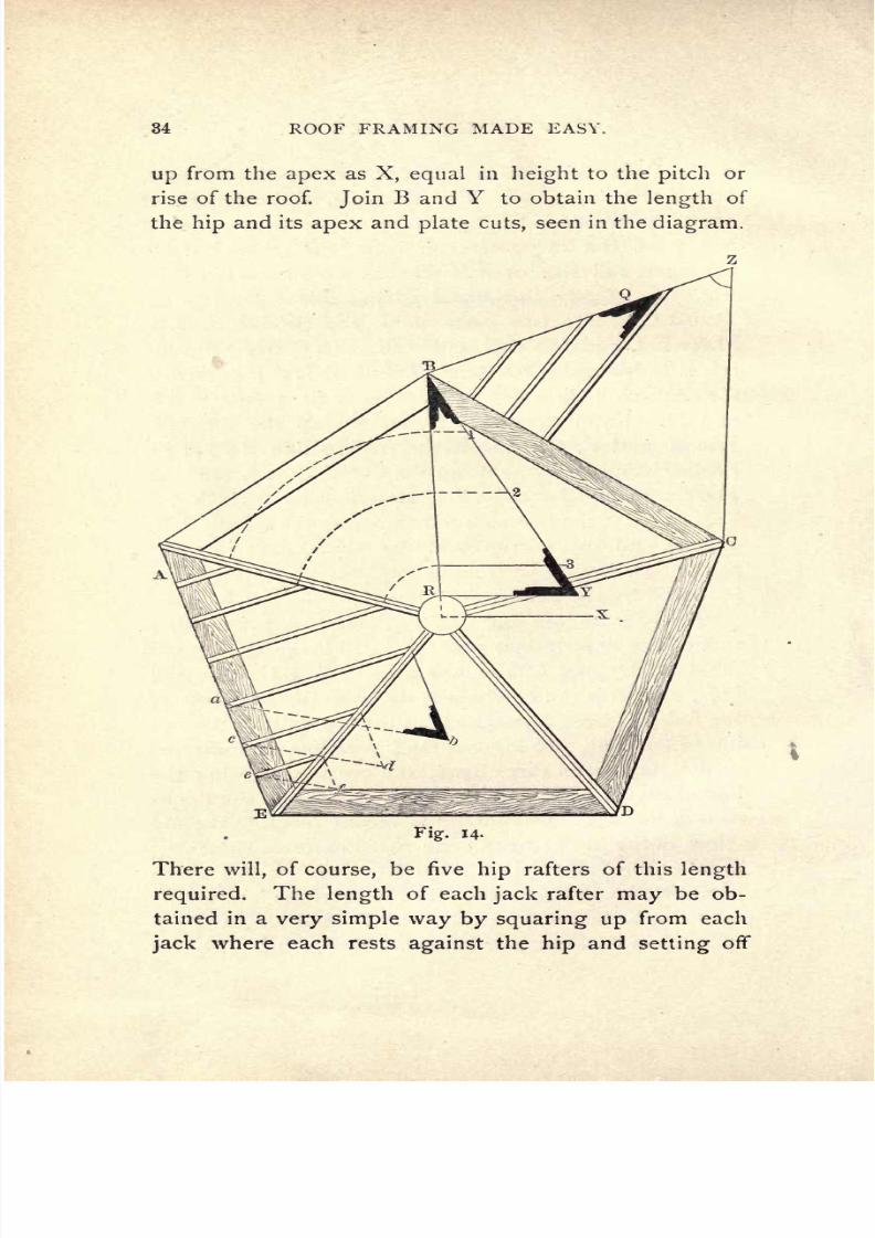
34
ROOF
FRAMING
MADE
EASY.
up
from
the
apex
as
X,
equal
in
height
to
the
pitch or
rise
of
the
roof.
Join
B
and
Y
to obtain the
length
of
the
hip
and
its
apex
and
plate
cuts,
seen
in
the
diagram.
Fig.
14-
There
will,
of
course,
be five
hip
rafters
of
this
length
required.
The
length
of
each
jack
rafter
may
be
ob-
tained
in
a
very
simple
way by squaring
up
from
each
jack
where
each
rests
against
the
hip
and
setting
off

7/25/2019 Roof Framing Made Easy 1903
http://slidepdf.com/reader/full/roof-framing-made-easy-1903 37/174
ROOF
FRAMING
MADE
EASY.
35
each
height
of
the
jacks,
thus
determining
the
exact
length
of B Z
C,
being
the
devolopment
of
the B
R
C.
The
side
bevel will
be
as
Q,
which
must
be
reversed
for
jack
on
opposite
sides of
the
hips:
There will
be five
sets
with
a
right-hand
side
bevel
and five
sets with
a
left-hand
side
bevel.
Regarding
the
backing
of
the
five
hip
rafters,
the
first
thing
to
be
done
is
to find
the
desired
bevel.
This
is
easily
accomplished
by
taking
any
point,
as
s,
Fig.
15,
and from
s,
drawing
square
to
E
R,
as
O
P.
From
Fig.
15.
s,
let
fall a
line
perpendicular
to E
Y,
as s
t.
With
s
as
centre
and
s
t as
radius,
describe
the
circle s
t u
cut-
ting
R
E,
at
u.
Join
u
P and
u
O.
O
u
P,
will
be
the
bevel of
the
backing
and
a
bevel
may
be
set
to
one
side
of
the
rafter.
7/25/2019 Roof Framing Made Easy 1903
http://slidepdf.com/reader/full/roof-framing-made-easy-1903 38/174
ROOF
FRAMING
MADE
EASY.
CHAPTER
VII.
Hexagonal
Pyramidal
Roofs.
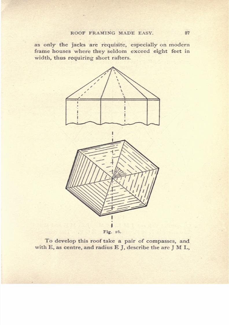
Readers
will
see at
Fig.
16
the
top
and
side
views
of
a
hexagonal
or
six-sided
roof,
or
one which
has
a
wall
plate
running
round on six
walls as
shown
above,
the
dotted
lines
representing
the
angle
lines
of
the
hex-
agonal
figure.
The
completed
roof
with
the
boarding
or
tin on
will
appear
as shown
on
the
lower
sketch.
In
order
to
frame
this
roof
the
following system
should
be
used
:
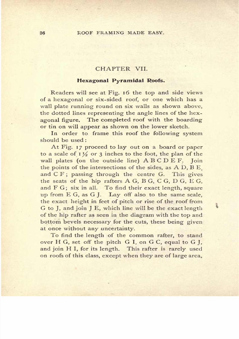
At
Fig.
17
proceed
to
lay
out
on
a
board
or
paper
to
a scale of
I
^
or
3
inches
to
the
foot,
the
plan
of the
wall
plates
(on
the
outside
line)
A
B
C
D
E
F.
Join
the
points
of
the intersections
of
the
sides,
as
A
D,
B E
)
and
C
F
;
passing
through
the centre
G.
This
gives
the seats
of
the
hip
rafters
A
G,
B
G,
C
G,
D
G,
E
G,
and
F
G;
six
in all. To
find
their
exact
length,
square
up
from
E
G,
as
G
J.
Lay
off
also
to
the
same
scale,
the
exact
height
in
feet
of
pitch
or
rise
of
the
roof
from
G
to
J,
and
join
J
E,
which
line will be
the
exact
length
of
the
hip
rafter
as seen in
the
diagram
with
the
top
and
bottom
bevels
necessary
for
the
cuts,
these
being given
at
once
without
any
uncertainty.
To
find
the
length
of
the
common
rafter,
to
stand
over
H
G,
set
off
the
pitch
G
I,
on
G
C,
equal
to
G
J,
and
join
H
I,
for
its
length.
This rafter
is
rarely
used
on roofs
of
this
class,
except
when
they
are
of
large
area,
7/25/2019 Roof Framing Made Easy 1903
http://slidepdf.com/reader/full/roof-framing-made-easy-1903 39/174
ROOF
FRAMING
MADE
EASY.
37
as
only
the jacks
are
requisite,
especially
on
modern
frame houses
where
they
seldom
exceed
eight
feet
in
width,
thus
requiring
short
rafters.
J
Fig.
i
6.
To
develop
this
roof take
a
pair
of
compasses,
and
with
E,
as
centre,
and radius E
J,
describe the are
J
M
L,

7/25/2019 Roof Framing Made Easy 1903
http://slidepdf.com/reader/full/roof-framing-made-easy-1903 40/174
38
ROOF
FRAMING
MADE
EASY.
cutting
H
G
produced
in
L.
Join
E
L
and
D
L
which
will
give
the
triangle
ELD which
is
the
covering
over
the
plan
E
G
D,
on the
pitch
or
rise
GJ.
Bisect,
or
rather
divide
E
F,
into
two
parts
at
Q. Square up
from
M
Fig.
17.
Q,
cutting
the
arc
J
M
L,
at
M.
Join
M
E and M F.
The
triangle
E
M
F,
will
lie
over
E
G
F.
The
remain-
ing
four
triangular
developments
or
coverings
can
be
laid
out
from
the
foregoing
by
making
J
O,
H
K,
R
N,
7/25/2019 Roof Framing Made Easy 1903
http://slidepdf.com/reader/full/roof-framing-made-easy-1903 41/174
ROOF FRAMING MADE
EASY.
39
and
S
P,
equal
in
length
to
Q
M,
or a
simpler
method
would
be
to
take
G,
as centre
with
G
M,
as a radius and
describe short
arcs
cutting
O,
K,
N,
and
P,
thus
giving
the exact
lengths
at
one
sweep,
and
insuring
their be-
ing
alike
so
as to meet
at
the centre G when folded.
The side
bevel at
K,
will make
the
top
cuts
on
the
jack
rafters
fitting
against
the
hips,
the bottom cuts fit-
ting
on
the
plates being
the
bevel
at
H.
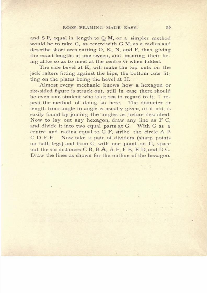
Almost
every
mechanic
knows
how
a
hexagon
or
six-sided
figure
is
struck
out,
still
in
case
there
should
be
even
one
student
who is
at
sea
in
regard
to
it,
I
re-
peat
the method of
doing
so
here.
The diameter
or
length
from
angle
to
angle
is
usually
given,
or
if
not,
is
easily
found
by
joining
the
angles
as
before
described.
Now
to
lay
out
any
hexagon,
draw
any
line
as
F
C,
and
divide
it
into
two
equal
parts
at
G.
With
G
as
a
centre
and
radius
equal
to
G
F,
strike the
circle
A
B
C
D E
F.
Now
take
a
pair
of dividers
(sharp
points
on
both
legs)
and
from
C,
with
one
point
on
C,
space
out the
six distances
C
B,
B
A,
A
F,
F
E,
E
D,
and
D
C.
Draw
the
lines
as
shown for
the outline
of
the
hexagon.
7/25/2019 Roof Framing Made Easy 1903
http://slidepdf.com/reader/full/roof-framing-made-easy-1903 42/174
40
ROOF
FRAMING
MADE
EASY.
CHAPTER
VIII.
Conical
Roofs.
Having
treated
the usual
forms
of
roofs
embracing
the
hip
and
valley principles,
I
will now
draw
attention
to the
proper
laying
out and
framing
of a roof
on
a cir-
cular
tower,
as this
form
occurs
very
often
in
modern
houses,
barns,
etc. The
methods
to be
followed
in
this
chapter
are
very
simple,
so that
an
ordinary
mechanic
can
easily
understand
them
if he
only
studies the
dia-
gram
and
text
a
little.
Supposing
A,
B,
C,
D,
E,
F,
G,
H,
on
Fig.
1
8 to
be
the
plan
or
plate
line
of
the
roof,
and
O
L,
the
pitch
or
rise,
it
can be
laid
out
as
follows
: To be more
explicit
I
will
take
it for
granted
that a
carpenter
has a
roof
to
frame
with
a
plan
A,
B, etc.,
of
6
feet
diameter,
or
6 feet
from
C
to
G,
and
9
feet
rise,
or
9
feet
from
O
to
L.
Proceed
to
strike the
plan
A,
B,
etc.,
either full
size
or
to
scale.
It
is
always
better
to
lay
out
full
size
if
a
floor
or
drawing-board
can
be
found
big
enough
to
do
it,
but
if
not half size
or a scale
of
3
inches or I
y
inches
to the
foot
may
be
used.
Having
struck the
circle draw
centre lines for
the
rafters
A
E,
B
F,
C
G,
and
D
H,
and set
off
the thick-
ness
of
the rafters
as
they
show on
the
plan.
Next
draw
any
straight
line
as
J
K,
the
same
length
as
C
G
;
raise
up
the centre line O
L,
the
height
of
the
pitch,
and
join
L
K,
which will
be
the
length
of
the
rafters
to stand

7/25/2019 Roof Framing Made Easy 1903
http://slidepdf.com/reader/full/roof-framing-made-easy-1903 43/174
ROOF
FRAMING
MADE
EASY.
41

7/25/2019 Roof Framing Made Easy 1903
http://slidepdf.com/reader/full/roof-framing-made-easy-1903 44/174
42
ROOF
FRAMING MADE
EASY.
over
A
I,
B
I,
C
I,
D
I,
E
I,
F
I,
and
G
I
and
the
top
and
bottom
cuts
will
be
directly given
;
as
at L
and
J,
L
M
and
L N are
the
rafters
I D
and 1 F
placed
in
po-
sition
and
L
O
is
the rafter
E
I in
position. By
refer-
ring
to
Fig.
19
the
rafters
B
I,
A
I and
HI will
be seen
at
the
rear of the
figure.
If
the
roof is
to
be
boarded
vertically,
horizontal
strips
or
sweeps
will
require
to
be
sawn
out
and
nailed
in
the
manner
represented
in
both
Figs.
18
and
19.
To
do
this
properly,
divide the
height
from
O to
L in
Fig.
1
8
and draw the
lines
representing
the
sweeps
as I
1,22,
3
3,
4 4,
and
5
5.
The
neat
length,
and the
cuts to fit
against
the
sides of
the
rafters
may
be
determined
by
striking
out
the
sweeps
shown on
the
plan,
I
I,
2
2,
3 3,
44,
and
5
5.
It
will be
noticed
that
this
roof will re-
quire
8
circular
pieces
for each
row,
or
40
sweeps
in
all.
One
pattern
will
do
for
each
sweep
and
the
remaining
8
needed
can be
marked from
each
pattern.
Fig.
19
will
convey
a
better
idea
of
the
constructed
roof,
as
this
illustration
represents
each
stud,
plate,
rafter
and
sweep
in
its fixed
position,
with the
covering
boards
nailed
on
half
way
round.
In
order
to
find
the
exact
shape
and bevels
for
the
covering
boards,
a
very
simple
method is
used,
thus
:
Take
a
pair
of
compasses,
or a
trammel
rod,
and
with
L
as
centre,
(Fig.
18),
and
L P
as
radius,
describe the
arcs
J
P,
equal
to the
semi-circle
A
B
C
D
E.
and
K
O,
equal
to
the
semi-circle
A
H
G
F
E.
Join
L P and
L
Q,
now
divide
J
P
into
12
equal spaces
with
a
pair
of
compasses,
and
join
the
division
marks
on
J
P
with
L.
This will
give
12
tapering
boards
and
the
bevel
at
X on
the
plan
will
be the
bevel
of the
jointed
edges.
As

7/25/2019 Roof Framing Made Easy 1903
http://slidepdf.com/reader/full/roof-framing-made-easy-1903 45/174
ROOF
FRAMING
MADE
EASY.
43
Fig.
19.

7/25/2019 Roof Framing Made Easy 1903
http://slidepdf.com/reader/full/roof-framing-made-easy-1903 46/174
44
ROOF FRAMING
MADE
EASY.
twelve
boards
will
be
needed
for
half
the
plan,
twenty-
four will
have
to
be
cut out
for
the other
half,
so
it
will
be seen
that
if
the
sweep
or
arc
J
P
goes
round
from
A
B,
etc.
to
E,
the
sweep
K
Q
will
go
round
H,
K,
G,
etc.,
to
E.
The
diminishing
lines from
the
point
L
to
the line
J
P
are the
inside
lines
of the
joints
of the
boards
shown
also
in
Fig.
19.
In
order
to
prove
the
accuracy
of
the
foregoing,
a
model
can be made
by
drawing
the
roof
to
scale
on
cardboard,
and then
cutting
out the
figures
from
L
to
J,
from
J
to
K,
and
from
K
to
L. Also cut out the
fig-
ures
L P
J,
and
L
Q
K.
Now
if L
J
K be
stood
up
over
A
E,
B
F, etc.,
it
will
be
seen
to
fit
over
each.
In a
similar
way
the
figure
L
J
P
will bend around
A B
C
D
E
with the
peak
L
over
the
point
I
and the
line
J
P
around
A
B
C
D
E.
In a
like
manner
K
Q
will
bend around
A
H
G
F
E,
and L
will
lie over
I,
thus
proving
the
correctness
of
the methods
followed.
Care
must
be
taken
to
allow
for
the
intervening
rafters
when
framing
the
peak
cuts
of
the
rafters.
7/25/2019 Roof Framing Made Easy 1903
http://slidepdf.com/reader/full/roof-framing-made-easy-1903 47/174
ROOF
FRAMING
MADE
EASY.
45
CHAPTER
IX.
To
Frame
a
Conical
Roof
Intersected
by
a
Pitched
Roof.
As
this
is
a roof
which
occurs
in
many
cases,
espec-
ially
in
railroad
work,
it will be
found
both
interesting
and
useful.
Let
A
E
F
B,
Fig.
20,
be
the
plan
or wall
plate
of
the
conical
dome,
and A D
B,
the
diameter,
D
C the
rise
or
pitch.
Join
A
C,
to
obtain
the
lengths
of
the
common
rafters
which will
radiate
from
the
centre
C,
round
the
circular
plate
A
E
F
B
r
with
the
top
and
bot-
tom bevels
as
represented
at C
and
A.
On account
of
the
pitched
roof
C
H
F,
the
gable
end
of
which is G
I
H,
with
pitch
J
I,
equal
in
height
to
D
C,
intersecting
or
cutting
into the
conical
dome,
there
will
be a
valley
rafter. The
seat
of
this
valley
will be
D
F,
because
J
I,
being
equal
to
C
D,
the
ridge
J
E,
will
be
the
same
height
as
the
conical
apex
or
peak
D.
To
obtain the
length
of
the
valley
rafter,
square
up
from
D
on
D
F,
and
with
D,
as centre
and D
C,
as
rad-
ius,
cut
off
the
length
D
K,
equal
to
D
C.
Join
F
K,
this
will
be the
length
of the
valley,
and as
D
B,
is
equal
to D
F,
and
the
pitches
D
C,
and
D
K,
are
equal,
there-
fore
the
valley
will
be
the
same
length
s
common
rafter.
To
find
the
lengths
of
jack
rafters,
proceed
to
Fig.
21,
and
lay
out
the
ridge
and
valley
rafter as
before.

7/25/2019 Roof Framing Made Easy 1903
http://slidepdf.com/reader/full/roof-framing-made-easy-1903 48/174
46
ROOF
FRAMING
MADE
EASY.
T
Fig.
20.
LAYING
OUT
OF
ROOF.
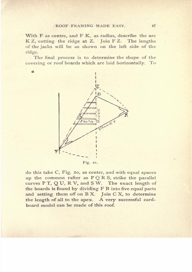
7/25/2019 Roof Framing Made Easy 1903
http://slidepdf.com/reader/full/roof-framing-made-easy-1903 49/174
ROOF
FRAMING MADE
EASY.
47
With
F
as
centre,
and
F
K,
as
radius,
describe the
arc
K
Z,
cutting
the
ridge
at
Z.
Join
F
Z.
The
lengths
of
the
jacks
will be
as shown
on
the
left side
of the
ridge.
The final
process
is
to determine the
shape
of the
covering
or
roof
boards
which are
laid
horizontally.
To
Fig.
21.
do
this
take
C,
Fig.
20,
as
center,
and
with
equal
spaces
up
the
common rafter as
P
Q
R
S,
strike the
parallel
curves
P
T,
Q
U,
R
V,
and
S
W. The
exact
length
of
the boards
is
found
by
dividing
F
B
into
five
equal
parts
and
setting
them
ofif
on
B
X.
Join
C
X,
to
determine
the
length
of
all to
the
apex.
A
very
successful
card-
board
model
can
be
made
of
this roof.

7/25/2019 Roof Framing Made Easy 1903
http://slidepdf.com/reader/full/roof-framing-made-easy-1903 50/174
48
ROOF
FRAMING
MADE
EASY.
CHAPTER
X.
Octagonal
Roofs.
At
Fig.
22,
A B
C
D
E
F
G H
is
the
plan
of
the
oc-
tagonal
roof.
I
is
the
centre
or
peak.
A
I,
B
I,
etc.,
Fig.
22.
are
the
seats
of
the
hips.
L
J
is the
length
of
the com-
mon
rafters. B
K
is
the
exact
length
of
the
hip
rafters.
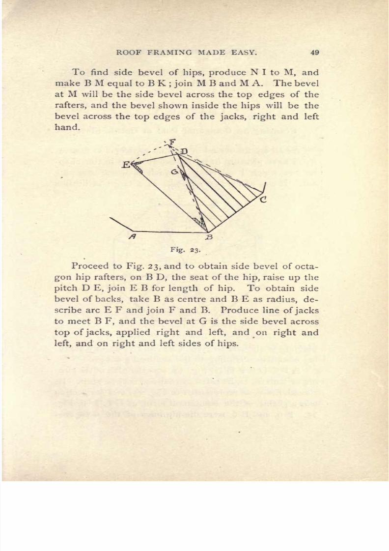
7/25/2019 Roof Framing Made Easy 1903
http://slidepdf.com/reader/full/roof-framing-made-easy-1903 51/174
ROOF
FRAMING
MADE
EASY. 49
To
find
side
bevel
of
hips,
produce
N I
to
M,
and
make
B
M
equal
to
B
K
;
join
M
B
and
M
A.
The bevel
at
M
will
be
the side bevel across the
top edges
of
the
rafters,
and
the
bevel
shown
inside
the
hips
will
be the
bevel across
the
top
edges
of
the
jacks,
right
and left
hand.
Proceed
to
Fig.
23,
and
to
obtain
side
bevel
of
octa-
gon hip
rafters,
on
B
D,
the
seat
of
the
hip,
raise
up
the
pitch
D
E,
join
E
B
for
length
of
hip.
To obtain
side
bevel
of
backs,
take
B
as
centre
and B E
as
radius,
de-
scribe arc
E
F
and
join
F
and B.
Produce
line
of
jacks
to meet
B
F,
and
the
bevel
at
G
is
the side
bevel across
top
of
jacks,
applied
right
and
left,
and
on
right
and
left,
and
on
right
and
left
sides
of
hips.

7/25/2019 Roof Framing Made Easy 1903
http://slidepdf.com/reader/full/roof-framing-made-easy-1903 52/174
50 ROOF FRAMING
MADE
EASY.
CHAPTER
XL
Framing
an
Octagonal
Roof
of Gothic
Style.
As
all
are interested
in
unusual
problems
in
carpen-
try,
I
have
pleasure
in
laying
before
them
in
this
chap-
ter
one
which
I
solved
and
which
is
worth
studying
out. It was erected on
a
cupola
of
a
large
institution
Fig.
24.
building
in
the
city
of
New
York,
and
is
to-day
stand-
ing
complete
according
to
the architect's
design.
ABCDEFGH,
Fig.
24,
was
the
plan
of
the
cup-
ola
or
lantern,
eight-sided
in
shape
as
will be
seen.
Its
elevation
was
as
represented
in
Fig.
25,
and
its
section
was
a
gothic
of the
equilateral
form,
as G
6,
D
6,
Fig.
25.
F
6,
and
E
6,
were the
hip
lines of the
octagonal

7/25/2019 Roof Framing Made Easy 1903
http://slidepdf.com/reader/full/roof-framing-made-easy-1903 53/174
ROOF.
FRAMING
MADE
EASY.
51
plan
to
stand
over
the seats
F
6,
and
E
6,
on
Fig.
24.
The radius
of
the
gothic
was
as
shown
on
the
elevation,
and
from
this we will
proceed
to
lay
out
the
roof and
get
the curves
for the timbers
as shown
in
Fig.
26.
From
the
points
T,
U,
V,
W,
X,
draw
lines
square
to
Q
6,
as
TL, UM,
VN,
WI,
X.
From the
space
points
on
the
line
QZ,
make
the
dotted
lines
equal
in
length
individually
to
TL,
UM,
VN,
WI,
X;
and
draw
Fig.
25.
through
the
points the
curve
Z
Y
G.
Produce
US,
and WR
to
Y
and
Y',
and
the
lines
SY' and
RY
will
denote the curved
jack
rafters.
The
bevel at
Y,
is
that
which
will
fit
against
the
side
of
the
hip
rafter as
the
development
G,
Z,
Q,
will
fold and
stand
over
the
G
6,
Q.
The
curve
of
the
jacks
will
be
same
as G
6,
Fig.
24,
and struck from the same
radius.
This
will be read-
ily
understood
by
an
examination
of
the
diagram,
Fig.
26.
The
bevel at
6,
Fig.
25,
will
be
the
plumb
cut
of
the
jack
rafters.

7/25/2019 Roof Framing Made Easy 1903
http://slidepdf.com/reader/full/roof-framing-made-easy-1903 54/174
53
ROOF
FRAMING
MADE
EASY.
In
order
to find
the
length
and
curve
of
the hip
rafters which
will
stand over the
seats,
A
6,
B
6,
C
6,
D
6,
E
6,
F
6,
G
6,
H
6-
Fig.
24,
proceed
as
follows :
Take
any
octagonal
triangle
as
G
6
F,
Fig.
24,
and
lay
it off as G
6
F,
Fig.
26,
G
6,
being
a level
line.
From
Fig.
26.
6
raise
up
a
plumb
line
as
6,
6'.
Next
divide the
gothic
sweep
on
Fig.
25,
G
6,
into
six
equal
parts,
as
I,
2,
3,
4,
5,
6,
and
carry
these
over
to
the centre
line
as
indi-
cated. Transfer
these to
6
6',
Fig.
26.
Next divide
the
line
G
6,
into six
equal
parts,
as
T,
U,
V,
W,
X,
and

7/25/2019 Roof Framing Made Easy 1903
http://slidepdf.com/reader/full/roof-framing-made-easy-1903 55/174
ROOF FRAMING
MADE
EASY.
53
from
the
points
of
division
raise
up
plumb
lines.
Also,
draw level
lines
from
the
points
i',
2',
3',
4',
5',
on
6
6',
cutting
the
plumb
lines from
G
6,
at
the
points
I,
2,
3,
4, 5,
6.
Draw
the
curve
G
I,
etc.,
through
these
points
and this curve
will
be
the exact
shape
of
the
hip
rafter
required
to
stand
over
the
eight
seats
seen
on
Fig.
24.
For
the
jacks
divide
the
plate
G
F,
Fig.
26,
into
six
equal parts
and
draw lines
square
to the
plate
for
the
seats
of
the
jacks,
as
will be
seen
from
A
to
H,
Fig.
24.
These
will
join
with the
lines
2
U,
4
W,
at
the
points
U
and
W
on the
line G 6.
Produce
them
indefinitely
out-
side
G
F.
Now
take
the
divisions
H
A,
Fig.
24,
and
set them
off
on
the
line
Q
Z,
Fig.
26,
and
draw
lines
square
to
Q
Z.

7/25/2019 Roof Framing Made Easy 1903
http://slidepdf.com/reader/full/roof-framing-made-easy-1903 56/174
54 ROOF
FRAMING
MADE
EASY.
CHAPTER XII.
Framing
an
Octagonal
Molded
Roof.
The molded
roof
which
I
propose
to
treat
in
this
chapter
is
one
which
may
not
be
familiar
to
readers
and
may
seem
difficult to
lay
out.
Various
methods have
been
put
forward for
the
purpose
of
getting
the
exact
cuts,
etc.,
for
these
roofs,
but there have been
none
so
far
sufficiently
intelligible
to
apply practically.
I
have,
therefore,
worked
out
one
of
the
most
usual
forms
for
the
benefit
of the
trade
at
large.
The
first
roof
is
a
regular
ogee
molded
tower
roof on an
octagonal
or
eight-sided
plan,
or,
in
other
words,
the
plate
is
eight-sided,
as
represented
at
Fig.
29,
where
the
plan
of
the rafters
is
denoted,
including
both
hips
and
jacks. CDEFGHIJ
is
the
eight-
sided
plate,
and
eight
sides have a molded
plane
termi-
nating
in a
point
at
L,
shown in
the
layout,
Fig.
30.
As
there
may
perhaps
be some
readers
who
are
not
entirely
familiar
with
the
proper ways
of
making
an
eight-sided
figure
or
octagon,
I
will
explain
this
here.
Let
a
b
y
Fig.
27,
be
one
side
of
the
octagon,
say
4
feet
long,
it is
required
to
construct
the
full
octagon
8
feet
6
inches
wide.
To
do this :
With the steel
square
or
bevel,
draw a d
and
b
c on
a
miter,
and
make each
4
feet
long;
then from
c
and
d,
draw
c e
and
d
h,
square
to
a
b.
Next
from
e
and
//,
draw e
f
and
h
g
t
on
a
miter
of
45
degrees,
and
make
each
4
feet
long
;
join g
and
f
to
complete
the
figure.
This
alone
is
one
way
to
do
it,

7/25/2019 Roof Framing Made Easy 1903
http://slidepdf.com/reader/full/roof-framing-made-easy-1903 57/174
ROOF
FRAMING MADE
EASY.
55
and a
very
simple
one.
Fig.
28
shows
another
way
:
Let
a
d,
d
c
and c
b be
any
square, say
8 feet
6
inches
wide. Draw
the
diagonals
from
corner
to
corner,
as a
c
and
b
d,
cutting
in
e.
Now with the
compasses
set
to
c
c
mark
the sides
at
j
and
/%
also
at
///,
etc.
Join
these
points
and
the
eight-sided
figure
will
be
given,
as
shown
by
the
heavy
black
lines
in
the
engraving.
By
either
of
the
above methods
the
plate
line,
C
D
E
F
G
H
I
and
J
of
the
plan, Fig.
29,
may
be
exactly
Fig.
27.
laid
out,
or if
the
cuts
or
octagon
mitres
are
to be
found,
the
figures
7
and
17
on
the
steel
square
will
give
the
cut.
The writer
prefers,
however,
to
lay
out
roofs
of
this
character
full
size,
on
an
extemporized
floor
or
drawing-board
and to
strike
out the
rafters
also
full
size
with
a
trammel
rod,
a
bradawl
and
a
pencil.
K A B L
Fig.
30,
is
the
profile
of
the
roof,
K
A and
K
B
being
jack
rafters,
which
will stand
over
those
marked
on
Fig.
29
;
A
corresponding
to
A,
and
B
to B.
The
bevel
at
X,
is
the
side bevel
of the
jacks fitting against
the
hips,
right
and left. The
layout
will
explain
this
very
clearly.
To find
the
exact
shape
of the
hip
curve,
as
P
10'
Fig.
30,
draw
O
10',
the seat
of one
octagon
angle
or

7/25/2019 Roof Framing Made Easy 1903
http://slidepdf.com/reader/full/roof-framing-made-easy-1903 58/174
56
ROOF
FRAMING
MADE
EASY.
i
2-
30-
LAYOUT
OF
ROOF.
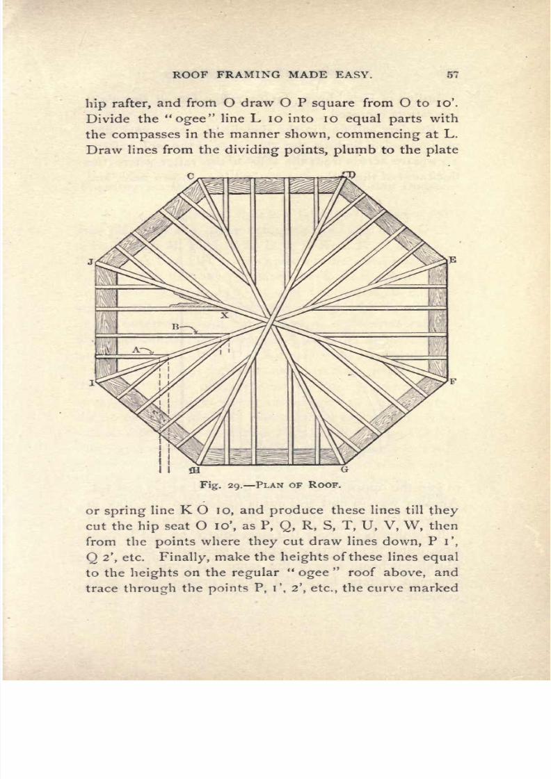
7/25/2019 Roof Framing Made Easy 1903
http://slidepdf.com/reader/full/roof-framing-made-easy-1903 59/174
ROOF
FRAMING
MADE
EASY. 57
hip
rafter,
and
from
O
draw
O
P
square
from
O to 10'.
Divide
the
ogee
line
L
10 into
10
equal
parts
with
the
compasses
in
the
manner
shown,
commencing
at
L.
Draw
lines
from
the
dividing points, plumb
to
the
plate
Fig. 29.
PLAN OF
ROOF.
or
spring
line
K
O
10,
and
produce
these
lines
till
they
cut the
hip
seat O
10',
as
P,
Q,
R,
S,
T,
U,
V, W,
then
from
the
points
where
they
cut draw
lines
down,
Pi',
O
2',
etc.
Finally,
make
the
heights
of
these
lines
equal
to the
heights
on
the
regular
ogee
roof
above,
and
trace
through
the
points
P,
T,
2',
etc.,
the curve
marked
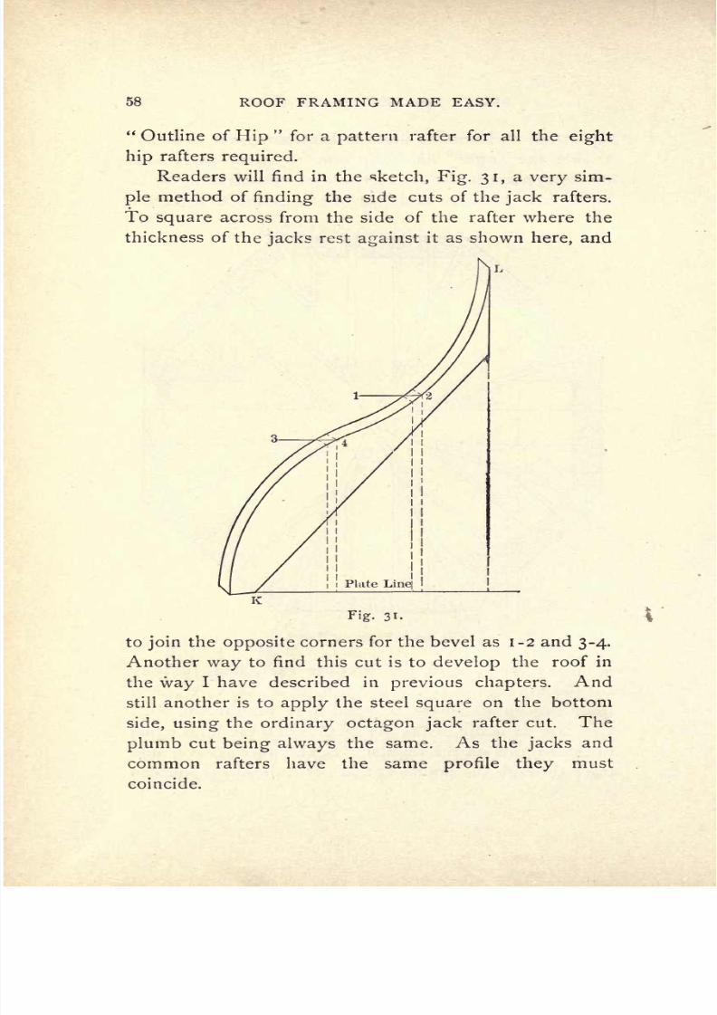
7/25/2019 Roof Framing Made Easy 1903
http://slidepdf.com/reader/full/roof-framing-made-easy-1903 60/174
58
ROOF FRAMING
MADE
EASY.
Outline
of
Hip
for
a
pattern
rafter
for
all
the
eight
hip
rafters
required.
Readers
will
find
in
the
sketch,
Fig.
31,
a
very
sim-
ple
method
of
finding
the
side cuts
of
the
jack
rafters.
To
square
across
from
the
side
of
the rafter
where the
thickness
of
the
jacks
rest
against
it
as
shown
here,
and
Fig.
31-
to
join
the
opposite
corners
for
the
bevel
as
1-2
and
3-4.
Another
way
to
find
this
cut is
to
develop
the
roof
in
the
way
I
have
described
in
previous
chapters.
And
still another
is
to
apply
the
steel
square
on
the
bottom
side,
using
the
ordinary
octagon
jack
rafter cut.
The
plumb
cut
being
always
the
same.
As
the
jacks
and
common
rafters
have
the
same
profile
they
must
coincide.
7/25/2019 Roof Framing Made Easy 1903
http://slidepdf.com/reader/full/roof-framing-made-easy-1903 61/174
ROOF
FRAMING
MADE
EASY.
59
CHAPTER
XIII.
Framing
an
Octagonal
Roof
with
a
Circular
Dome.
At
Fig.
32,
let A
B
C
D
E F
G
H,
be
the
plan
of
the
wall
plates
of
the
main
octagonal
roof
and
H
O,
G
O,
G
N,
F
N,
F
M,
E
M,
E
L,
D
L,
D
K,
C
K,
C
Z,
B
Z,
B
J,
A
J,
A
I and
H
I,
the
seats
of the
octagonal
hip
rafters.
The
intervening
planes
between the
hips
will
be circular
surfaces
as
O
N,
and
the
rafters,
if
cut
in
horizontally
as
shown
in
the
engraving,
will
be
curved
on
the
outer
edge
and
each sawn
to
a
different
radius
using
the
centre
of
the
octagonal plan
and
upper
circu-
lar
plate
J
Z K L
M
N
U O
I,
as
a
fixed
centre
and
in-
creasing
the
radius
for each
sweep
as
they go
down
on
the
pitch
in
the
manner
seen
in
Fig.
33,
where
the
sweeps
are
represented
cut
in between
two
hip
rafters,
the
bottom
cuts
of
which rest
at the
angle
of
hip;
this
will
also be
seen
on
the
plan Fig.
32,
as
G
O
and
G
N.
The
upper
ends
or
cuts
of
the
octagonal
hips
are
cut
to,
and notched
tinder,
the
upper
circular
plate
which
car-
ries the
studding,
forming
the
drum
of
the
dome.
Concerning
the
length
of
the
hips, jacks,
and
com-
mon
rafters,
readers
will find
the
simplest
method
of
de-
termining
their
length
to
be
that
shown on
the
diagram
Fig.
32.
To
obtain
the
length
of
the
main
hips
as
G
N,
and
so
on,
lay
off
the
seat
F
M,
and
square
up
from
M,
as
M
R.
Join
R
F,
which
will
be the
exact
length
of
the
hip,
to
scale,
and
R,
and
F,
will
be
the
top
and
bot-

7/25/2019 Roof Framing Made Easy 1903
http://slidepdf.com/reader/full/roof-framing-made-easy-1903 62/174
60
ROOF
FRAMING
MADE
EASY.
H
Fig.
32.
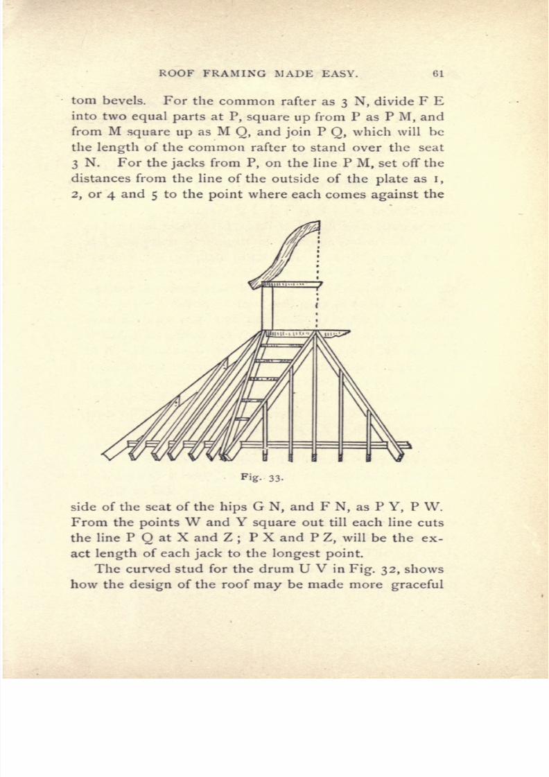
7/25/2019 Roof Framing Made Easy 1903
http://slidepdf.com/reader/full/roof-framing-made-easy-1903 63/174
ROOF
FRAMING
MADE
EASY. 61
torn
bevels. For
the
common
rafter
as
3
N,
divide
F E
into
two
equal
parts
at
P,
square
up
from P
as
P
M,
and
from
M
square
up
as
M
Q,
and
join
P
Q,
which
will be
the
length
of the
common
rafter
to
stand over
the
seat
3
N.
For
the
jacks
from
P,
on
the
line P
M,
set
off the
distances
from
the
line
of
the
outside
of
the
plate
as
i,
2,
or
4
and
5
to
the
point
where
each
comes
against
the
Fig-
33-
side
of
the
seat
of
the
hips
G
N,
and
F
N,
as
P
Y,
P
W.
From the
points
W
and
Y
square
out till each line
cuts
the
line
P
Q
at
X and
Z
;
P
X
and
P
Z,
will
be
the
ex-
act
length
of
each
jack
to
the
longest
point.
The
curved
stud for
the
drum
U
V
in
Fig.
32,
shows
how
the
design
of
the
roof
may
be
made
more
graceful

7/25/2019 Roof Framing Made Easy 1903
http://slidepdf.com/reader/full/roof-framing-made-easy-1903 64/174
62
ROOF
FRAMING
MADE
EASY.
by
introducing
curved
studs
instead
of
the
straight
studs
seen
in
Fig.
33.
ST
shows
the
ogee
rafters
of
the
top
or
dome,
and
with
its rise
or rim.
A
B
C
on
the
top
of
the
engraving
illustrates
how
this
roof
may
be devel-
oped
in
the
way
I
have illustrated
and
explained
in
the
previous
chapters,
as
I
have
by
slow
degrees
led
up
from the
simplest
to
intricate
roofs
and their
framing.

7/25/2019 Roof Framing Made Easy 1903
http://slidepdf.com/reader/full/roof-framing-made-easy-1903 65/174
ROOF
FRAMING MADE
EASY.
63
CHAPTER
XIV.
To
Frame
a
High
Pitched
or
Church
Roof.
At
Fig.
34
let
A B
C
D E
F
G
H I
J
K L
be the
plan
of the
wall
plates.
Around
to
B
will
be
a
circular
end.
B
Y
the
pitch
or
length
of
common
rafter
which will
space
along
the
plate
from
B
to C
and
from
A
to L.
The
bevel
at
Y
will be
the
one
required
for
the
top
cut
against
the
ridge
and
that at
B
the
bevel
for
and
on
the
wall
plate.
Similar
rafters will
require
to
be
cut
for
the
semi-circular
end
and
they
will
be
spaced
out
equally
round
it
as
I
have
drawn
them
half
way
round
from
B
to
8.
On
account
of
fitting
the
top
or
peak
ends of
these
rafters
where
they
group
at
the
top
it
is
advisable
to insert
a
circular
boss
or
block
to
fit
them
against
;
and
the
half
thickness
of
this block
must
be
cut
from
the
ends
of the rafters
on
the
plumb
cut.
This
is shown
at
X
in the
engraving.
The
ridge
X Y
will
also
require
to
be
fitted
to
it
and
the
common
side
rafters
A
X
and
B
X.
S
T
is
the
common
rafter
square
to
the
plate
and
T
U
its exact
length
which
will be
found
to
be
the same
length
as
B
Y.
C
P,
F
P,
L P
and I P
are the
seats
of
the
valley
raft-
ers
with
the
jacks
which will
fit
against
all four.
I
have
drawn these
on
one
side
only
as
the
other three
are
duplicate
rafters
with
the
cuts
reversed.
The
top
cut
is
the
same
as
Y,
and
the
bottom
side
cut
as
W,
which
may
be
found
by
developing
the roof.
Z
is
the
top
cut

7/25/2019 Roof Framing Made Easy 1903
http://slidepdf.com/reader/full/roof-framing-made-easy-1903 66/174
64
ROOF
FRAMING
MADE
EASY.

7/25/2019 Roof Framing Made Easy 1903
http://slidepdf.com/reader/full/roof-framing-made-easy-1903 67/174
ROOF
FRAMING
MADE
EASY.
65
of
the
valley
found
by
raising
up
the
pitch
P
Z
equal
to
X Y
and
joining
Z
I
and
Z
C,
and
the
bevel at C
is
the
bottom cut
of
valleys.
In
order
to
develop
the
planes
of
the
roof
produce
the line C
T
B
to
any
length.
Produce
A
X B
to
N
and
with
a
pair
of
compasses
strike
the
arc
N
Y
cutting
B
N
at
N,
through
N
draw
N
U
R
parallel
to
C
T
B
and
pro-
duce
S
T
to
U,
also
draw
P
through
Q
to
R,
and
set
off
the
valley
and
jacks
in
the
manner
shown.
Next
set
a
pair
of
dividers
to
one of the
spaces
round
B
8
and
set
off
the
eight equal
spaces
from
B
to
O.
Join
N
O.
If
the
whole
diagram
be
laid out
on
a
sheet
of
Bristol
or
cardboard
a
model
may
be made and the
system
proven
by
cutting
the
cardboard
with
a
penknife
or chisel
from
A
to
B,
thence
to
O,
thence
to
N,
N
to
R,
R
to
P,
P
to
C
and
so
on
as
before
described.
The
shape
of
the cov-
ering
boards
may
be
determined
by taking
Y,
as
centre
and
with
a
length
Y
A
striking
the
sweep
Y
M,
then
set-
ting
off
on
Y
M
1 6
spaces
each
equal
in
length
to
I,
2,
etc.
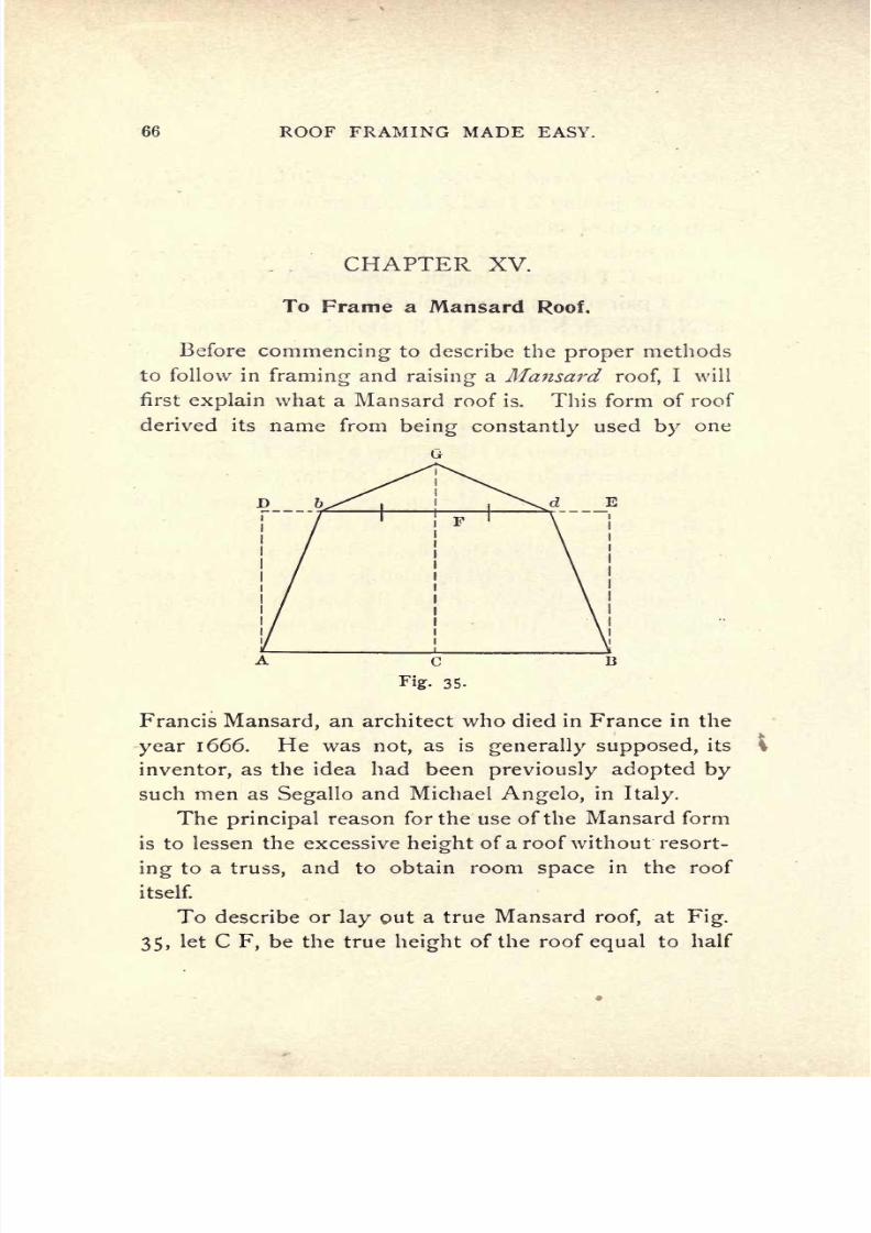
7/25/2019 Roof Framing Made Easy 1903
http://slidepdf.com/reader/full/roof-framing-made-easy-1903 68/174
66
ROOF
FRAMING
MADE
EASY.
CHAPTER
XV.
To
Frame
a Mansard
Roof.
Before
commencing
to
describe the
proper
methods
to
follow
in
framing
and
raising
a
Mansard
roof,
I will
first
explain
what
a
Mansard
roof
is.
This form
of
roof
derived
its
name from
being
constantly
used
by
one
A
c
B
Fig.
35.
Francis
Mansard,
an architect
who
died
in
France
in
the
year
1666.
He was
not,
as is
generally supposed,
its
inventor,
as the
idea
had
been
previously
adopted by
such
men
as
Segallo
and
Michael
Angelo,
in
Italy.
The
principal
reason for the
use
of
the
Mansard
form
is to
lessen
the
excessive
height
of a
roof
without resort-
ing
to a
truss,
and
to obtain
room
space
in
the
roof
itself.
To describe
or
lay
out
a
true
Mansard
roof,
at
Fig.
35,
let
C
F,
be
the
true
height
of
the
roof
equal
to
half

7/25/2019 Roof Framing Made Easy 1903
http://slidepdf.com/reader/full/roof-framing-made-easy-1903 69/174
ROOF
FRAMING
MADE
EASY.
G?
the
width
on
the
plate
line
C
B.
Draw
D
E,
parallel
to
A
B,
and
make
D
F,
and
F
E,
equal
to
A
C,
and
C
B.
Join
A
D,
and E
B.
Divide
D
F,
and F
E,
into
three
equal
parts
and
join
A
B
and
B
D.
Make
F
G,
equal
to
d
E,
and
join
b
G,
and G
d,
thus
obtaining
the
true
form
of
the
Mansard roof.
At
Fig.
36
another
way
to
describe
this
roof
is
shown,
and
this
resembles
more
the
old
colonial,
or
what
A
C B
Fig.
36.
is
called
the
American curb
roof.
To describe it strike
the
semi-circle
A E
D
F
B,
from
the
centre
C,
with
C
D
as a
radius.
Divide
the semi-circle
into
4
equal
parts
at
E,
D
and
F.
Join
A
E,
E
D,
D
F,
and
F
B,
which
will
give
the
proportional
form
of the
roof.
Fig.
38
will
give
the
reader
a
full
conception
of
the
framing
timbers
of
a
Mansard
roof
as
they
will
appear
when
raised.
They
consist
of
the
usual
wall
plate
and
an
upper
plate
which
is
supported by
the
flaring
or
sloping
side
rafters
which form
the
Mansard
chamber or
attic within.
Reference to
the
cross-section,
Fig.
37,
will
make
it
clearer
to
the
mechanic,
as
A,
is
the
wall
plate.
E,
the
upper
or
Mansard
plate supported
by
the
Mansard
or
flaring
rafters
C,
which
flares
2
feet
off
the

7/25/2019 Roof Framing Made Easy 1903
http://slidepdf.com/reader/full/roof-framing-made-easy-1903 70/174
68
ROOF
FRAMING
MADE EASY.
perpendicular.
D,
is
the
deck
or
upper
rafters,
and
B,
a tie
or
ceiling
beam which
gives
a
good
attic
room.
Half
the
roof
only,
namely,
the left
side,
is
shown
in
the
cross-section,
Fig.
37.
Fig.
37.
A
comparison
between
the
plan Fig.
39,
and the
elevation
and cross-section
will make
clear
the full
con-
struction
of
the
roof
and
enable
any
mechanic
to
lay

7/25/2019 Roof Framing Made Easy 1903
http://slidepdf.com/reader/full/roof-framing-made-easy-1903 71/174
ROOF
FRAMING
MADE
EASY.
RidgS
Upper
urd
Wall
Plate
Fig.
38.
ELEVATION OF
FRAMING.
Wall
Plate
PLAN
OF
MANSARD RAFTERS.

7/25/2019 Roof Framing Made Easy 1903
http://slidepdf.com/reader/full/roof-framing-made-easy-1903 72/174
70
ROOF
FRAMING
MADE
EASY.
out,
frame and
raise
roofs
of
this
class.
The
eleva
ion
and
plan
show
one end
(the
right)
hipped
and
the other
(the
left)
gabled.
In
order
to
determine
the exact
Fig.
40.
length
of
the
Mansard
hip
rafter,
the
method
is
illus-
trated
in
Fig.
40.
It
is
simply
to raise
up
on
the
seat
X
Z,
of
the
hip
the
height
of
the
pitch
9
feet
and
6
inches,
and
to
join
this
height
with Z.
The deck
or
upper
rafters are
framed
in
the
way
I
previously
described.
Fig.
41
represents
the
proper
Top
Cuts
of
Mansard
Rafters
L
Fig.
41.
shape
to
frame
the
top
cuts of Mansard
rafters
to
pre-
vent
their
slipping
under
the
upper
plate.

7/25/2019 Roof Framing Made Easy 1903
http://slidepdf.com/reader/full/roof-framing-made-easy-1903 73/174
ROOF
FRAMING
MADE
EASY.
71
CHAPTER
XVI.
Hemispherical
Domes.
The
roof
presented
to
readers
of this
chapter
is
one
well
worthy
of careful
study
and
working
out.
It
is
of
a
kind
which occurs on
many
houses
now-a-days
on
the
tops
of
towers
for
domes,
etc.
I
should therefore
recommend
that
all who have leisure time should
work
it
out
on a
board
to
a
large
scale.
A
B
C
D E
F
G,
Fig.
42,
is
the
plan,
a
perfect
circle,
of
twelve feet
diameter
or
six
feet
radius,
A D and
B
F
two
diameters
or
centre
lines
intersecting
in
the
centre.
The
dome
is
hemispherical
or
half
a
ball,
or
sphere,
therefore the elevation
H
J
I,
is
struck
from a six
foot
radius.
A
pair
of
trammel
points
and
rod
may
be used
in
striking
out
these
curves,
but,
should
these
be lack-
ing,
a
y
by
7/&
inch
strip
and a
couple
of
brad awls will
do
the
job very
handily.
H
I
are
the plates
made
of
two
thicknesses
of
stuff ,
and
I
J
one
pattern
rafter.
J
is
the
top
cut
and
I
the
bottom
cut.
They
are,
of
course,
similar.
The
rafters
for this roof
may
be
gotten
out
of
I
J^
or
2 inch
stuff ,
fastened
at
the
joint
by
a
cleat
as
shown at
I
J.
There
will
be
eight
rafters
required
(if
it
is
intended to
cover
it
vertically)
as
B
X,
C
X,
D
X,
E
X,
F
X,
G
X,
A
X,
and
3
X.
Those
will
have
horizontal
sweeps
nailed
in
between
them
denoted here
by
I,
2,
3,
4,
5,
in
the
ele-
vation. The
exact
position
of
these
sweeps
is deter-

7/25/2019 Roof Framing Made Easy 1903
http://slidepdf.com/reader/full/roof-framing-made-easy-1903 74/174
ROOF
FRAMING
MADE
EASY.
Fig.
42.
METHODS FOS.
OBTAINING
SHAPE
OF
COVERING
BOARDS.

7/25/2019 Roof Framing Made Easy 1903
http://slidepdf.com/reader/full/roof-framing-made-easy-1903 75/174
ROOF
FRAMING
MADE
EASY.
73
mined
by
dividing
the
quarter
circle
H
J
into six
equal
parts
and
then
from
the
division
points, drawing
.lines
parallel
to H
I.
These
will
be
the
centre
lines
of
the
edges
of
the
sweeps.
Similarly
they
are
shown on the
plan
below
as
i'
, 2',
3', 4',
5',
to
X,
which is
as
they
will
look
from
above.
Their
exact
length
for each course
from
I
to
5
will be
found
by
measuring
the
sweeps
from
A
X to
G
X,
de-
ducting
half
the
thickness'
of
the rafters
on
each end.
Patterns should
be
made
for
each
course
as
it
will be
seen
that
each
is struck
from
a
different
radius,
short-
ening
as
they
ascend
to
the
top
:
I
in
the
plan
corre-
sponding
to
i in
the
elevation
and so
on
up.
It
will,
therefore,
be
clearly
understood
how to
frame such
a
roof as
this when
boarded
or
covered
vertically.
To
find
the exact
shape
and size
of the
covering
boards,
take
any
one of
the six
divisions
and set it
off
on
each
side of
G,
the
point
where
X
G,
cuts
the
quarter
circle
A
F,
at G
;
produce
X
G,
indefinitely.
Now,
with
the
dividers
set
off
on
G
S,
the
six
distances,
H
I,
i
2,
2
3, 3
4, 4
5, 5
J
on
the
elevation
;
and
draw
lines
from
these
points
square
to G
S.
Next,
again
with
the
divid-
ers,
make
these
squared
lines
each
equal
in
length
to
the dotted
lines
passing through
G
X,
from T
to
U,
and
draw
the curves
as
shown,
which will
give
the exact
length
and
curvature
of
the
boards to be
bent
round
I
J.
There
will
be six
of these
for each
quarter
circle
on
plan
or
24
for
the
whole
roof.
If
this
be
laid
out
on
a
cardboard
sheet cut
out
and
folded
it
will be found
to
fit
exactly.
To
cover
this
roof
horizontally,
all the
rafters,
24
in
number,
must
be
set
vertically
or
plumb,
as
B
X,
i
X,

7/25/2019 Roof Framing Made Easy 1903
http://slidepdf.com/reader/full/roof-framing-made-easy-1903 76/174
74
ROOF
FRAMING
MADE
EASY.
2
X,
etc.,
to
A
X,
and
it
would
be
best
to
have
a
finial
or
block
at
the
top
to receive
the
top
ends
of
the
rafters.
In
order
to
find
the
shape
of
the
level
covering
boards,
divide
the curve
Fig.
43,
into
6
equal
parts
and
draw
lines from
division
points
parallel
to
plate.
Join
A
I,
Fig.
43-
I
2,
2
3,
3
4, 4
5,
5
6,
and
produce
these
joining
lines
till
they
cut the
centre
line
produced
indefinitely.
The
points
where
these
produced
lines
intersect
the centre
line
will
be
the
centres
for
the curves of
the
covering
boards
as
represented
in
the
engraving.

7/25/2019 Roof Framing Made Easy 1903
http://slidepdf.com/reader/full/roof-framing-made-easy-1903 77/174
ROOF
FRAMING MADE
EASY.
75
CHAPTER XVII.
To Frame a Circular
Elliptic
Dome.
Readers will observe
that
I
have
here
treated
a
roof
with
which most
mechanics
are
unfamiliar,
and
it
is
a
pleasure
for
me
to
describe it for
this
reason.
A
C
D
B,
Fig.
44,
is the
plan
or
outside
line
of
the
plates
which
measure 12'
o x
20'
o ,
or
the
roof wilt
be
20
feet
long
and
1
2
feet
wide. Across
I
K
R
its section
will
be
a
semi-circle,
as
at A
E B and across F K
S
its
section
will
be a
semi-ellipse
(not
an
oval,
as
this
figure
is
often
miscalled).
As
there
may
probably
be
some
readers
who are not
acquainted
with
the
proper
methods
of
striking
a
semi-ellipse,
as A
M'
L'
H
C
really
is
we
will
proceed
to
illustrate
and
describe
the best
in
use.
In
referring
to
the
engraving,
Fig.
45,-
we
will
sup-
pose
A
B
to be 20 feet
long
and
C
D
6
feet
equal
to
the
I
H on
Fig.
44.
Now
to
find a
curve
closely
resembling
that
of
the
ellipse
draw
the
line
E
C
F
parallel to
A
D
B,
and
draw
A
E
and
B
F.
Now divide
the sides
E
C
and C
F each
into
five
equal
parts
as
1,2,
3,
4,
and
E
and
join
these
dividing
points
with
the
angle
A,
as
4A,
3
A,
2A,
I
A,
and CA.
Similar lines
are
drawn on
the
other
side
to
B.
After
this
is
done,
divide
the sides
AE
and
BF
each
into
five
equal
parts
and
join
the
dividing
points
with
C, as
AC,
iC,
2C,
etc.
;
do
likewise
on
the
side
BF.
Next
proceed
to
trace
the
elliptic
curve
through
the
points
where
the
joining
lines
intersect each
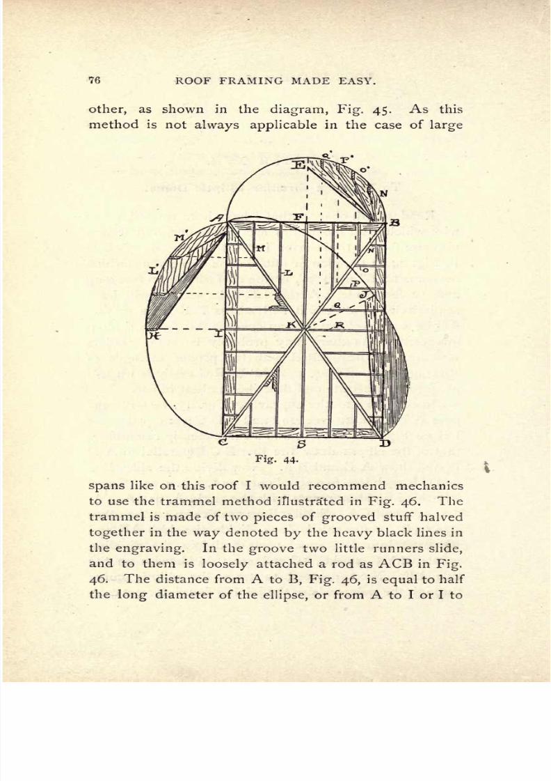
7/25/2019 Roof Framing Made Easy 1903
http://slidepdf.com/reader/full/roof-framing-made-easy-1903 78/174
76
ROOF FRAMING
MADE
EASY.
other,
as
shown
in
the
diagram,
Fig.
45.
As
this
method
is
not
always
applicable
in
the case
of
large
Fig.
44-
spans
like
on
this
roof
I
would
recommend mechanics
to
use
the
trammel
method
illustrated
in
Fig.
46.
The
trammel
is
made
of
two
pieces
of
grooved
stuff
halved
together
in
the
way
denoted
by
the
heavy
black
lines
in
the
engraving.
In
the
groove
two little runners
slide,
and
to
them
is
loosely
attached
a
rod
as
ACB
in
Fig.
46.
The
distance
from
A
to
B,
Fig.
46,
is
equal
to
half
the
long
diameter
of the
ellipse,
or
from
A
to
I or
I
to

7/25/2019 Roof Framing Made Easy 1903
http://slidepdf.com/reader/full/roof-framing-made-easy-1903 79/174
ROOF
FRAMING
MADE
EASY.
77
C,
on
Fig.
44,
and
the
distance
from
C
to
B
is
the
same
as the
height
on
from
I
to
H,
on
Fig.
44.
At
B the
pencil
is
placed,
and
being
moved
round,
as
it
were,
the
Fig.
45-
slides
run
in
the
grooves
and
the
pencil
follows
and
out-
lines the
desired
elliptic
curve.
By
means of
the
tram-
mel the
full
ellipse
may
be
outlined.
Fig.
47
gives
another,
but
less
accurate,
method
of
obtaining
this
Fig
46.
curve.
AB
is the
length,
CD
the
height.
Take
a
rod
and
set
off
the
length
AC
from
D
on
the
line
AB.
This
will
give
the
two
foci or
points
E
and
F.
Drive
nails
or
pins
into
these
points
and
to
them
attach
a
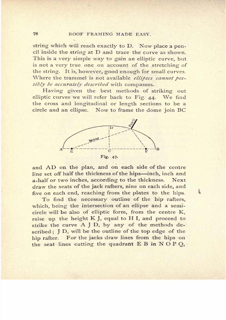
7/25/2019 Roof Framing Made Easy 1903
http://slidepdf.com/reader/full/roof-framing-made-easy-1903 80/174
78
ROOF
FRAMING
MADE
EASY.
string
which
will
reach exactly
to
D.
Now
place
a
pen-
cil
inside
the
string
at
D
and
trace
the
curve as shown.
This
is
a
very
simple
way
to
gain
an
elliptic
curve,
but
is
not
a
very
true
one
on
account
of
the
stretching
of
the
string.
It
is,
however,
good
enough
for
small
curves.
Where
the
trammel is
not available
ellipses
cannot
pos-
sibly
be
accurately
described
with
compasses.
Having
given
the
best
methods
of
striking
out
elliptic
curves
we will refer back
to
Fig.
44.
We
find
the
cross
and
longitudinal
or
length
sections
to be a
circle
and an
ellipse.
Now to frame the dome
join
BC
and
AD
on
the
plan,
and
on each
side of
the
centre
line
set
off
half the
thickness of the
hips
inch,
inch
and
a-half
or two
inches,
according
to the thickness.
Next
draw
the
seats
of the
jack
rafters,
nine
on each
side,
and
five
on
each
end,
reaching
from
the
plates
to
the
hips.
To
find
the
necessary
outline
of
the
hip
rafters,
which,
being
the
intersection
of an
ellipse
and
a
semi-
circle
will'
be
also
of
elliptic
form,
from
the
centre
K,
raise
up
the
height
K
J,
equal
to
H
I,
and
proceed
to
strike
the
curve
A
J
D,
by
any
of
the
methods de-
scribed
;
J
D,
will
be
the
outline
of
the
top edge
of the
hip
rafter.
For the
jacks
draw lines
from
the
hips
on
the
seat
lines
cutting
the
quadrant
E B
in
N
O
P
Q,
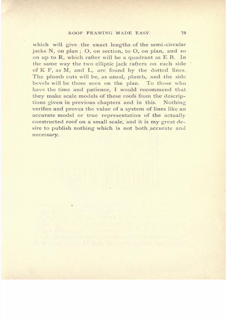
7/25/2019 Roof Framing Made Easy 1903
http://slidepdf.com/reader/full/roof-framing-made-easy-1903 81/174
ROOF
FRAMING MADE
EASY.
79
which
will
give the
exact
lengths
of the
semi-circular
jacks
N,
on
plan
;
O,
on
section,
to
O,
on
plan,
and
so
on
up
to
R,
which rafter
will
be
a
quadrant
as
E
B.
In
the
same
way
the two
elliptic
jack
rafters
on
each side
of
K
F,
as
M,
and
L,
are found
by
the dotted
lines.
The
plumb
cuts
will
be,
as
usual,
plumb,
and the
side
bevels
will be
those
seen on
the
plan.
To
those who
have
the
time
and
patience,
I
would recommend that
they
make scale
models
of
these
roofs
from
the
descrip-
tions
given
in
previous
chapters
and in
this.
Nothing
verifies and
proves
the value of a
system
of
lines
like
an
accurate model
or
true
representation
of
the
actually
constructed roof on a
small
scale,
and
it is
my
great
de-
sire
to
publish
nothing
which
is
not
both
accurate
and
necessary.
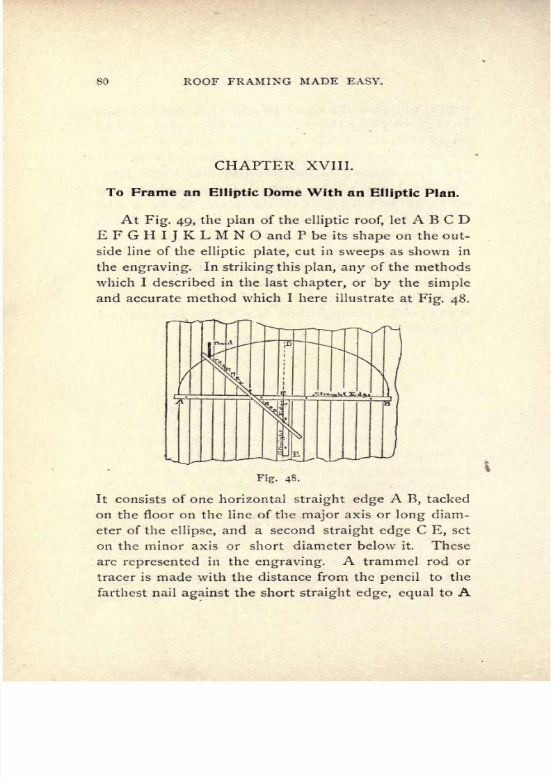
7/25/2019 Roof Framing Made Easy 1903
http://slidepdf.com/reader/full/roof-framing-made-easy-1903 82/174
80
ROOF
FRAMING
MADE
EASY.
CHAPTER
XVIII.
To Frame an
Elliptic
Dome With an
Elliptic
Plan.
At
Fig.
49,
the
plan
of
the
elliptic
roof,
let
A
B C
D
E F
G
H
I
J
K
L M N
O
and
P
be
its
shape
on
the
out-
side
line
of
the
elliptic
plate,
cut
in
sweeps
as
shown
in
the
engraving.
In
striking
this
plan,
any
of
the
methods
which
I
described in
the last
chapter,
or
by
the
simple
and accurate method
which
I
here
illustrate
at
Fig.
48.
Fig.
48.
It
consists
of
one
horizontal
straight
edge
A
B,
tacked
on
the floor
on the line
of
the
major
axis or
long
diam-
eter
of
the
ellipse,
and a
second
straight edge
C
E,
set
on
the
minor
axis or
short
diameter below it.
These
are
represented
in
the
engraving.
A
trammel
rod
or
tracer
is
made with the
distance
from the
pencil
to
the
farthest
nail
against
the
short
straight edge, equal
to
A

7/25/2019 Roof Framing Made Easy 1903
http://slidepdf.com/reader/full/roof-framing-made-easy-1903 83/174
ROOF
FRAMING
MADE
EASY.
81
C
or
half
the
long
diameter,
and
the
distance
from
the
pencil
to
the
nearest
nail
sliding against
the
long
straight
edge,
equal
to C
D
or
half
the
short
diameter.
The
elliptic
curves
may, by
this
method,
be
accurately
struck
to the
size
desired.
In
this
dome
roof
I
have
inserted a boss
in
the
cen-
tre
to
receive
the
top
cuts
of
the
elliptic
rafters,
all
of

7/25/2019 Roof Framing Made Easy 1903
http://slidepdf.com/reader/full/roof-framing-made-easy-1903 84/174
82
ROOF
FRAMING
MADE
EASY.
which
radiate
from
the
centre
to
the outside
edge
of
the
plate
terminating
at
A, B,
C,
D,
etc. The
rafters
which will
stand
over
the
plan,
Fig.
49,
on
M
E
will
be
bo
A
D
and
D
B
on
Fig.
50,
which is the
projection
or
view
of
elliptic
rafters
nailed
in
position.
Each
set
of two
rafters,
as
AI,
BJ,
CK,
DL,
Fig.
49,
etc.,
must
be
struck out
separately
with the
major
axis
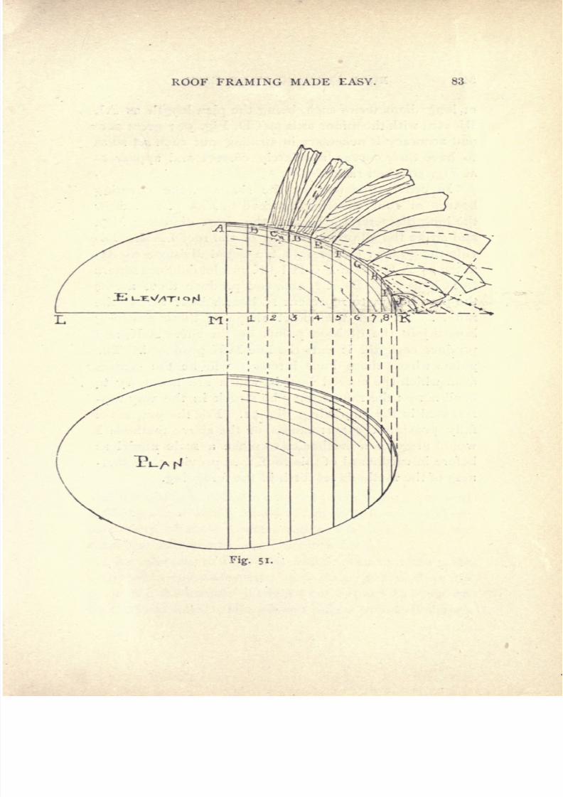
7/25/2019 Roof Framing Made Easy 1903
http://slidepdf.com/reader/full/roof-framing-made-easy-1903 85/174
ROOF
FRAMING
MADE
EASY.
83
Fig.
51.
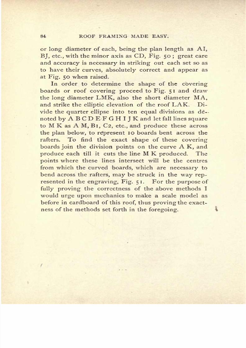
7/25/2019 Roof Framing Made Easy 1903
http://slidepdf.com/reader/full/roof-framing-made-easy-1903 86/174
84
ROOF
FRAMING
MADE
EASY.
or
long diameter
of
each,
being
the
plan length
as
AI,
BJ,
etc.,
with
the
minor axis
as
CD,
Fig.
50
;
great
care
and
accuracy
is
necessary
in
striking
out
each set
so as
to
have
their
curves,
absolutely
correct
and
appear
as
at
Fig.
50
when
raised.
In
order
to
determine
the
shape
of
the
covering
boards
or
roof
covering
proceed
to
Fig.
5
I
and
draw
the
long
diameter
LMK,
also
the
short
diameter
MA,
and
strike the
elliptic
elevation
of the
roof LAK.
Di-
vide the
quarter ellipse
into
ten
equal
divisions as
d--
noted
byABCDEFGHIJK
and
let
fall
lines
square
to
M
K as
A
M,
Bi, C2, etc.,
and
produce
these across
the
plan
below,
to
represent
10
boards
bent across
the
rafters.
To find
the exact
shape
of
these
covering
boards
join
the
division
points
on
the
curve
A
K,
and
produce
each
till
it
cuts the
line
M
K
produced.
The
points
where
these
lines
intersect
will
be
the
centres
from
which
the curved
boards,
which are
necessary
to
bend
across
the
rafters,
may
be
struck
in
the
way
rep-
resented
in
the
engraving, Fig.
51.
For
the
purpose
of
fully
proving
the
correctness
of
the above methods
I
would
urge
upon
mechanics
to
make
a scale
model as
before
in
cardboard
of
this
roof,
thus
proving
the
exact-
ness
of
the methods
set forth
in
the
foregoing.

7/25/2019 Roof Framing Made Easy 1903
http://slidepdf.com/reader/full/roof-framing-made-easy-1903 87/174
ROOF
FRAMING MADE
EASY.
85
CHAPTER
XIX.
Framing
a
Circular
Molded
Roof
Tower.
Having
before
described
the
proper
methods
to
be
followed
in
framing
a.
straight
sided
or
conical roof with
a
circular
base of
plan,
in
this
chapter
I
will
give
readers
the
information
necessary
to
know
in
laying
out
and
framing
a roof
with
a
molded
form of
rafter.
As
there
are
many
of
these
constructed
now-a-days
it
will
no
doubt be
welcome
to
studious
mechanics.
By
referring
to
Fig.
52
it
will be
seen
that the
plate
or
plan
is
a
complete
circle,
asABCDEFGH,
made
up
in
two
thicknesses
of
sweeps
cut out
as
I
have
shown
by
the
joint
lines.
The
molded rafters
(of
a
bell
shape)
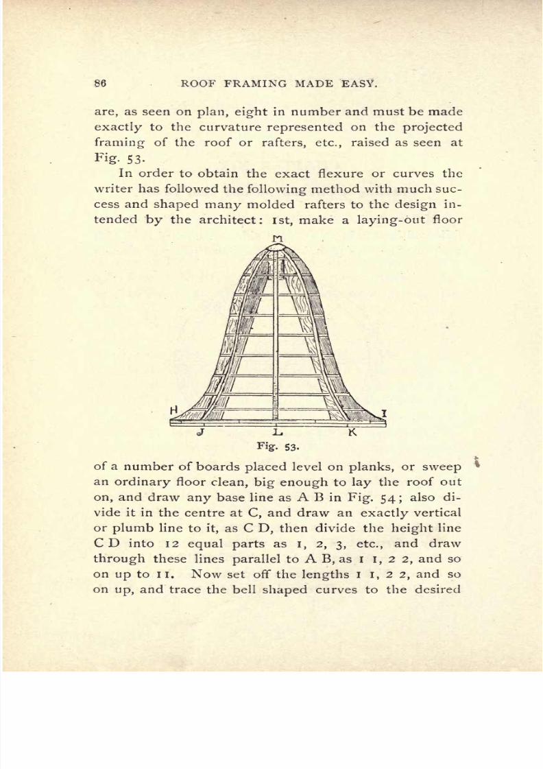
7/25/2019 Roof Framing Made Easy 1903
http://slidepdf.com/reader/full/roof-framing-made-easy-1903 88/174
86
ROOF
FRAMING
MADE
EASY.
are,
as
seen
on
plan,
eight
in
number
and
must
be
made
exactly
to
the
curvature
represented
on the
projected
framing
of
the
roof
or
rafters, etc.,
raised
as seen at
Fig.
53-
In
order
to
obtain
the
exact
flexure
or
curves
the
writer
has
followed
the
following
method
with
much suc-
cess
and
shaped
many
molded
rafters
to the
design
in-
tended
by
the
architect:
1st,
make
a
laying-out
floor
n
JL,
Fig.
53-
K
of
a
number
of
boards
placed
level
on
planks,
or
sweep
an
ordinary
floor
clean,
big
enough
to
lay
the
roof
out
on,
and
draw
any
base
line as
A
B
in
Fig.
54;
also
di-
vide
it
in the
centre
at
C,
and
draw
an
exactly
vertical
or
plumb
line
to
it,
as
C
D,
then
divide
the
height
line
CD
into
12
equal
parts
as
I, 2,
3,
etc.,
and draw
through
these
lines
parallel
to
A
B,
as
i
I,
2
2,
and
so
on
up
to
II.
Now
set
off
the
lengths
I
I,
2
2,
and
so
on
up,
and
trace
the
bell
shaped
curves
to
the
desired
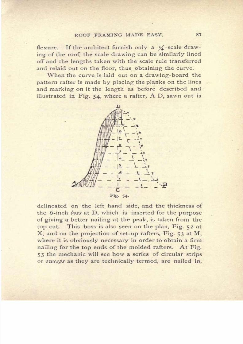
7/25/2019 Roof Framing Made Easy 1903
http://slidepdf.com/reader/full/roof-framing-made-easy-1903 89/174
ROOF
FRAMING
MADE EASY.
87
flexure.
If
the
architect
furnish
only
a
J^-scale
draw-
ing
of
the
roof,
the
scale
drawing
can
be
similarly
lined
off
and
the
lengths
taken
with the
scale
rule
transferred
and
relaid out
on
the
floor,
thus
obtaining
the
curve.
When the
curve
is
laid
out on
a
drawing-board
the
pattern
rafter
is made
by
placing
the
planks
on
the
lines
and
marking
on
it the
length
as
before
described
and
illustrated
in
Fig.
54,
where
a
rafter,
A
D,
sawn
out
is
delineated
on
the
left
hand
side,
and the
thickness of
the
6-inch
boss
at
D,
which
is
inserted
for
the
purpose
of
giving
a
better
nailing
at
the
peak,
is
taken from
the
top
cut.
This
boss is also
seen
on
the
plan,
Fig.
52
at
X,
and on
the
projection
of
set-up
rafters,
Fig.
53
at
M,
where
it
is
obviously
necessary
in
order
to
obtain
a
firm
nailing
for
the
top
ends
of
the
molded
rafters.
At
Fig.
53
the
mechanic
will see how
a
series
of
circular
strips
or
sweeps
as
they
are
technically
termed,
are
nailed
in,

7/25/2019 Roof Framing Made Easy 1903
http://slidepdf.com/reader/full/roof-framing-made-easy-1903 90/174
88 ROOF FRAMING
MADE
EASY.
ranging
from
the
plate
to
the
peak.
These
are
essen-
tial
when
it
is
intended
to
board the roof from
bottom
to
top,
for the
purpose
of
nailing
the
boards to
them.
They
are
sweeps
or arcs
of
circles
and
struck
from
different
radii,
decreasing
as
they
go up.
This
will
be
readily
understood
by
studying
the
plan,
Fig.
52,
where
the dotted
lines
represent
the
outside
edges
of
the
sweeps
shown
on
Fig.
53.
As there
are
8
intervening
spaces
between
the
rafters,
and
there
are
9
in
the
height,
there
will be
72
needed
altogether
or
8
of
each
kind,
and
they may
be
solidly
nailed
in
the
way
indicated
in
the
'engraving,
Fig.
53.
This
form of roof
may
be covered in
two
ways,
either
vertically
or
horizontally.
When covered
vertically,
the
sweeps
described above are
inserted
and
the
shape
of
the
covering
boards
determined,
in
the
following
man-
ner. Let
A
B
C
D E F
G
H I
J
K
L M N
O
P
on
Fig.
55
be
the
plan
of the
outside
edge
of
the circular
plate,
and A
X,
C
X,
E
X,
G
X,
I
X,
K
X,
M
X,
and
O
X
be
the
rafters,
all
abutting against
the boss
X,
on
plan,
in
the manner
seen at
D,
Fig.
54
;
-also
suppose
the
dotted
lines
on
Fig.
54
to
represent
the
outside
edges
of
the
sweeps.
To
determine
the
shape
of
one
covering
board,
produce
X
C
to
U
and
on the
line.C U,
taking
U
as
centre,
proceed
to
strike the arcs
a
b,
c
d,
e
f,
g
/i,
ij,
k
/,
;;/
n,
op,
q
r,
s
t
cutting
U C
at the
points
I, 2,
3, 4,
5,
6,
7,
8,
9,
10.
Then set
off
on each side
of the
line
U
C,
on
each
arc,
the distances from
X B
on
the
plan,
taking
the
exact
full
lengtJi
of
the
curve
and
not
on
a
straight
line,
each
corresponding
as
shown
in
the
engraving.
For
instance,
set
must
be
the
full
length
of
the
curve
BCD,
and
so
on
with each all
the
way
up.
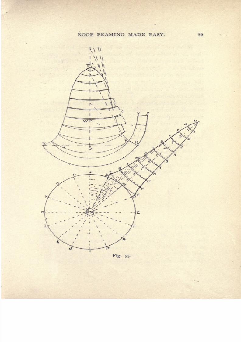
7/25/2019 Roof Framing Made Easy 1903
http://slidepdf.com/reader/full/roof-framing-made-easy-1903 91/174
ROOF
FRAMING
MADE EASY.
Fig.
55-

7/25/2019 Roof Framing Made Easy 1903
http://slidepdf.com/reader/full/roof-framing-made-easy-1903 92/174
90
ROOF
FRAMING
MADE
EASY.
If
the
roof
is
intended
to
be
boarded
horizontally
then
more
rafters
must
be
inserted,
in
order
to
give
a
better
nailing,
and
this
roof will
then
need
sixteen,
in-
stead
of
only eight,
as
before,
see
Fig.
55.
To obtain
the
shape
of the
horizontal
covering
boards,
proceed
to
the
upper
engraving
and draw
Q
R
equal
to
M
E
be-
low,
and
S
T
vertical
to
it.
Also
set
off
the
bell-shaped
curves
as
shown.
To
find
the
shape
of the
first
or bottom
board,
as-
sume
R
V
to
be a
straight
line,
and
produce
it till it cuts
the
vertical
line
S
T
at
W,
then with
W
as
centre and
radii
W
R and
W
V,
strike the
two
arcs
Q
R Z
and
Q
V
Y.
Finally,
to
find
the
exact
length
of
this
bottom
board,
take
any
curved distance
on
plan,
as
A
B,
Fig.
55,
and
set it
off
eight
times
from
Q
to
Z,
as
indicated
by
the
marks.
This will
give
half
way
round,
which
doubled
will
give
entire
circular
covering
board
for
the
first
section.
By continuing
this
process
up
to
the
top,
all
the
horizontal
boards
may
be
laid
out.
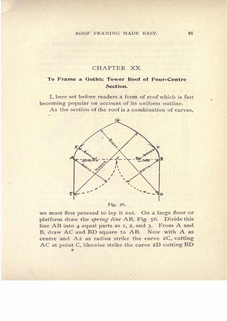
7/25/2019 Roof Framing Made Easy 1903
http://slidepdf.com/reader/full/roof-framing-made-easy-1903 93/174
ROOF
FRAMING MADE
EASY.
91
CHAPTER
XX.
To
Frame a
Gothic
Tower
Roof
of
Four-Centre
Section.
I,
here set
before
readers
a
form of
roof
which
is
fast
becoming
popular
on
account
of
its
uniform
outline.
As
the
section
of
the roof
is a
combination
of
curves,
CX--
Fig.
56.
we
must
first
proceed
to
lay
it
out.
On
a
large
floor
or
platform
draw
the
spring
line
AB,
Fig.
56.
Divide this
line
AB
into
4
equal parts
as
1,2,
and
3.
From
A
and
B,
draw
AC
and
BD
square
to
AB.
Now
with
A
as
centre
and A2
as
radius strike the
curve
2C,
cutting
AC
at
point
C,
likewise
strike the curve
2D
cutting
BD

7/25/2019 Roof Framing Made Easy 1903
http://slidepdf.com/reader/full/roof-framing-made-easy-1903 94/174
93
ROOF
FRAMING
MADE
EASY.
at
D. This
process
locates
the
desired centres
for
the
different curves
of
the
dome
or
tower
section.
With i
as
centre
and
I A
as
a
radius,
strike the
short
curve,
or
arc
A
E
and
with
3
as
centre
and
same
radius
strike B
F.
This
gives
2
arcs,
next
with
C
as
centre,
and
allowing
the
trammel
pencil
to be
just
tan-
gent
to
B F
at
F,
describe
the
arc F
G.
In
a
similar
Fig.
57-
manner describe
the
arc
E
G
on
the
left.
This
process
carefully
followed
out will
give
the
exact
four-centre
gothic
section,
but
it
must
not be followed
in
every plan
where
a roof
of this
section
is
shown,
as
the
position
of
the
centres
may
not be
placed
or
divided
off
as
is shown
above,
and
a detail
or
layout
of the
roof
may
be
neces-
sary
to
determine
their
position.
The
foregoing
de-
scription,
however,
will
make
the
work
familiar
and
easy.
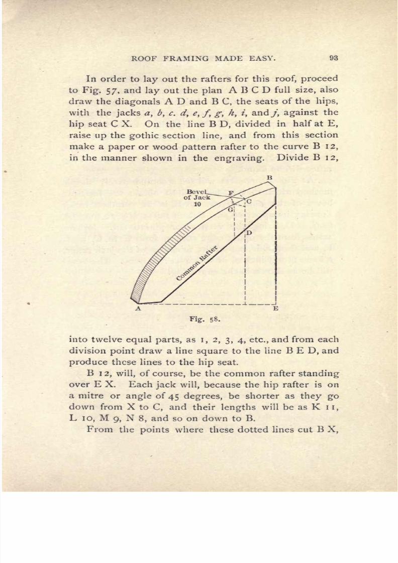
7/25/2019 Roof Framing Made Easy 1903
http://slidepdf.com/reader/full/roof-framing-made-easy-1903 95/174
ROOF
FRAMING
MADE
EASY.
93
In
order
to
lay
out
the
rafters
for
this
roof,
proceed
to
Fig.
57,
and
lay
out
the
plan
A
B
C
D
full
size,
also
draw
the
diagonals
A D
and
B
C,
the seats
of
the
hips,
with the
jacks
a,
b,
c.
d,
e,
f,
g,
//,
z,
andy,
against
the
hip
seat C X.
On
the
line
B
D,
divided
in
half at
E,
raise
up
the
gothic
section
line,
and
from
this
section
make
a
paper
or
wood
pattern
rafter
to
the
curve
B
12,
in
the
manner
shown
in
the
engraving.
Divide
B
12,
Bevel
__
of
Jack
10
Fig.
58.
into twelve
equal
parts,
as
I,
2,
3, 4,
etc.,
and
from
each
division
point
draw a
line
square
to the
line
BED,
and
produce
these
lines
to
the
hip
seat.
B
12,
will,
of
course,
be
the common rafter
standing
over
E
X.
Each
jack
will,
because
the
hip
rafter
is
on
a
mitre or
angle
of
45
degrees,
be
shorter
as
they
go
down
from
X
to
C,
and
their
lengths
will
be
as
K
II,
L
10,
M
9,
N
8,
and
so on
down
to
B.
From
the
points
where
these
dotted
lines
cut
B
X,

7/25/2019 Roof Framing Made Easy 1903
http://slidepdf.com/reader/full/roof-framing-made-easy-1903 96/174
94
ROOF
FRAMING
MADE
EASY.
draw up
square
to
B
X,
lines
of
an
indefinite
length.
Now,
commencing
from
B,
on
line
B
E,
take
the
first
division
I,
and
set off the
height
from
the
line
to
I,
on
the
first line
on
the
hip
seat,
also
height
at
2,
3,
4,
5,
and
so
on
up
to
12. To
be
explicit,
I
would
say
trans-
fer these
heights
from
perpendiculars
on
B
E,
to
per-
pendiculars
on
B
X.
Next
trace the
curve,
F
B,
through
the
points
12, 11, 10,
etc.,
and
the
proper
outline
of hip
rafter
will
be found.
At
Fig.
58,
readers will see a
comparatively
simple
method
which
may
be
followed
to
obtain the
top
side
bevel
of
the
jack
rafters.
A
B,
is
the
common
rafter
showing
its
upper
edge.
Set
off
rafter No.
10
from
A
to
C,
C
D,
being
the
vertical or
plumb
cut.
Square
across from
the
upper edge
corner,
from
G
to
C,
as
C
F,
and
from
C
D,
set
off
the thickness
of
the
jack
rafter,
2
inches,
or
3
inches,
or
whatever
it
may
be. The bevel
will be as
shown in
the
engraving.
7/25/2019 Roof Framing Made Easy 1903
http://slidepdf.com/reader/full/roof-framing-made-easy-1903 97/174
ROOF
FRAMING
MADE EASY.
95
CHAPTER
XXI.
To
Frame
a Trussed
Roof
of
Large
Span
on
the
Balloon
Principle.
That
carpentry
is
a
progressive
art
is
a truism
that
the
observer
will
not
hesitate to
admit,
and a
careful
examination
of
the
timber
structures
being
erected
in
the
United
States
to-day
will
impress
the
examiner
with
the
fact
that
it is also
a
liberal art.
This
is,
without
doubt,
one of the
chief reasons
why
wood
has
not
been
entirely
driven out
of
the fieW
by
its
great
competitor,
iron,
as it
can
be
readily
and
economically
employed
where the
latter
material
would be
inadaptable.
The
numerous
and
exceedingly
artistic
dwellings
which are
erected
in
all
parts
of the
country
attest
this,
and
while
designing
them
the architects
have
endeavored
to
devise
new
forms
of construction
which
might
enable them
to
produce
an
effective
design
and
at the
same
time
be
a
cheap
one
to
build.
An
illustration
of
this
will be
seen
in
the
sketches
which are
here
introduced,
as
they
ex-
plain
a
unique
method
of
balloon
framing
which
was
adopted
in
a
church,
the
building
being
a
frame
struc-
ture,
and
having
an
auditorium
measuring
56
feet
square.
The
architect
wished to
avoid
inserting
the
usual form
of
trusses
and,
after
careful
study,
he
devised
the
manner
of
construction
here
shown.
Fig.
59
is
the
plan
of
the
auditorium,
EAKDGCIBE
being
the
outside
line. B
F
A,
A
L
D,
D H
C
and
C
J
B
are
the

7/25/2019 Roof Framing Made Easy 1903
http://slidepdf.com/reader/full/roof-framing-made-easy-1903 98/174
96
ROOF
FRAMING
MADE
EASY.
trusses
which
the
reader
will
notice
do
not
span
the
roof
at
right
angles
in
the
way
generally
followed,
but are
placed
at
an
angle
of
45
degrees
across the
angle
of the
corner. Each
of
these
was
41
feet
on
base line and
were
framed
in
the
way
represented
in
the
isometrical
/*
\
\
/
A-
7
\/
/\
'
I,
i
Fig.
59-
projected
view
(Fig.
60),
without
any
tie
beam,
yet
of
a
form
statically
strong
enough
to
support
the rafters
and
shingling
placed upon
it.
They
were
then
placed
diagonally
across
the
plan
so
that their
seats
formed
a
square,
as
it
were,
within
a
square.
This
the
reader
will
comprehend
better
by referring
again
to
Fig.
59,
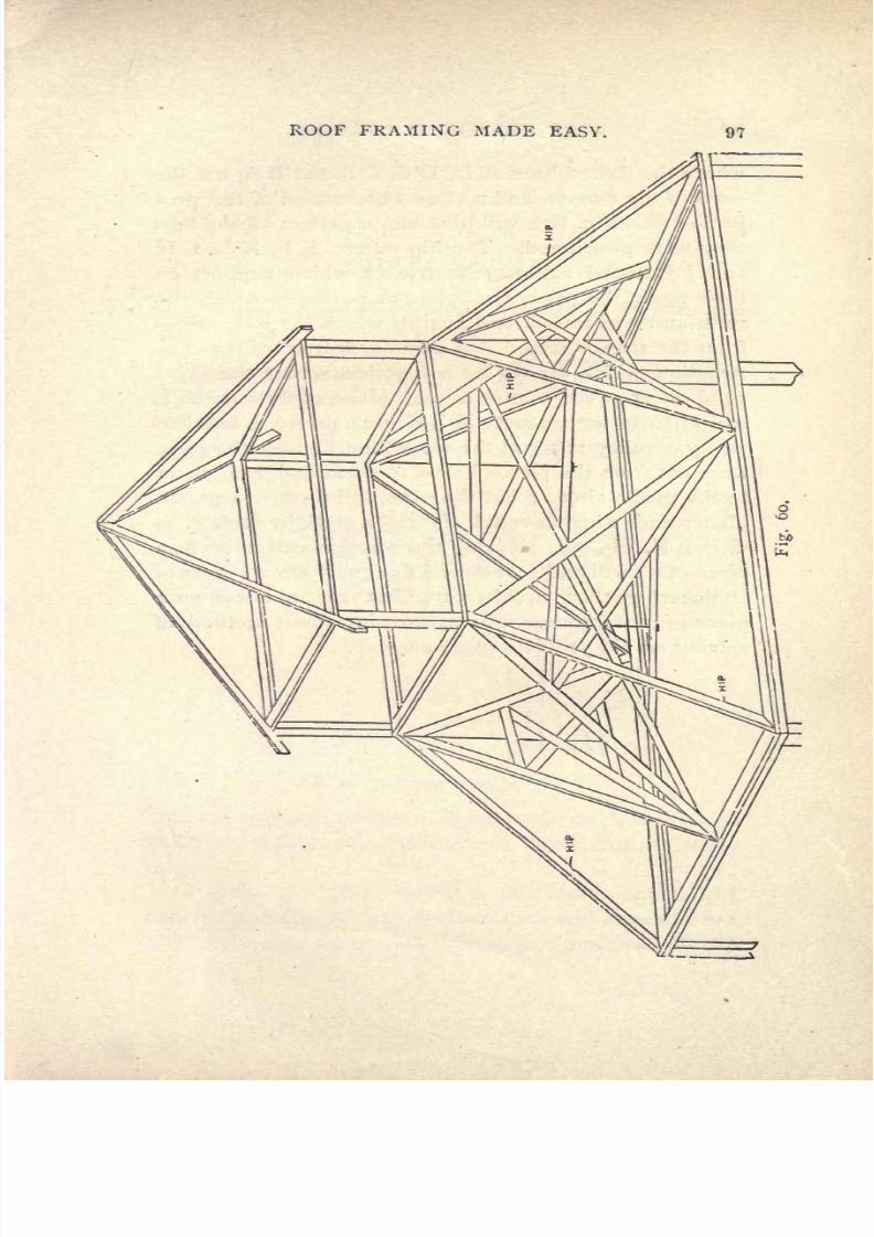
7/25/2019 Roof Framing Made Easy 1903
http://slidepdf.com/reader/full/roof-framing-made-easy-1903 99/174
ROOF
FRAMING
MADE
EASY.
97

7/25/2019 Roof Framing Made Easy 1903
http://slidepdf.com/reader/full/roof-framing-made-easy-1903 100/174
98
ROOF FRAMING
MADE
EASY.
where
the
dotted
lines
A
D,
D
C,
C
B
and
B
A,
are
the
seats of
the
trusses,
and
a
close observation
of
the
pro-
jection
(see
Fig.
60),
will
give
him
a
perfect
idea
of how
they
were
positioned.
The
hip
rafters,
E
F,
K
L,
G
H
and
I
J,
rested
against
the
trusses
which
support
on
their
peaks
the
upper
wall
plate
or
purlin
on which
the
ventilator
was
raised,
and
against
which
the
jack
rafters
from
the
trusses
rested.
A
peculiar
feature
of the
con-
struction,
which
the
reader
will
notice,
is
that
the
prin-
cipal
rafter
of the
trusses
in each
plane
of
three,
as D L
and
D
H,
in
the
plane
G
H L
K,
was
partly
a
hip
and
partly
a
valley
rafter
at
the
same
time,
because
the
jacks
were
cut
from
the
plates
below
to them
and from
them
to
the
purlin
above
;
but
the
sides still
formed
separate
planes and,
when
covered,
showed
a
straight
surface,
as
G
H
L
K,
Fig.
59.
Taking
the
whole construction as
a
piece
of statical
and economical
design,
it
savors
more of
engineering
than
architecture,
but
as
an
uncommon
piece
of
roof
framing
it
is
a most
ingenious
method
of
solving
an old
problem
in a
new
way.

7/25/2019 Roof Framing Made Easy 1903
http://slidepdf.com/reader/full/roof-framing-made-easy-1903 101/174
ROOF
FRAMING MADE
EASY. 99
CHAPTER XXII.
To
Frame a
Roof
of
Unequal
Heights
of
Pitches
and
Plates.
Having
described in
previous
chapters
roofs
spring-
ing
from
wall
plates
on the same
level,
I will
show
in
this the
proper
method
to
be
followed in
framing
two
roofs
where
the
plates
are
at different
heights
and the
Fig.
62. SECTION ON
LINE
A B.
roofs
at different
pitches.
These
roofs,
to
those unused
to
them,
appear
very
difficult to
frame,
but
are
really
not
so.
Fig.
6
1 will
give
readers a
full
conception
of
the
timbers
forming
the
two
roofs
as
they
will
appear
when
raised
or
set
up
in their
permanent
position.
It
will

7/25/2019 Roof Framing Made Easy 1903
http://slidepdf.com/reader/full/roof-framing-made-easy-1903 102/174
100 ROOF
FRAMING
MADE
EASY.
Fig.
61.
ROOF
TIMBERS
WHEN
RAISED.
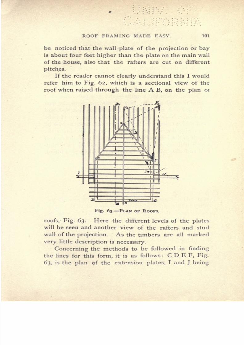
7/25/2019 Roof Framing Made Easy 1903
http://slidepdf.com/reader/full/roof-framing-made-easy-1903 103/174
ROOF
FRAMING
MADE EASY.
101
be
noticed
that
the
wall-plate
of the
projection
or
bay
is
about
four
feet
higher
than the
plate
on
the
main
wall
of the
house,
also
that
the rafters
are cut
on
different
pitches.
If
the
reader
cannot
clearly
understand this
I would
refer
him
to
Fig.
62,
which
is
a
sectional
view
of
the
roof
when raised
through
the
line
A
B,
on the
plan
01
r
Fig.
63.
PLAN
OF
ROOFS.
roofs,
Fig.
63.
Here
the
different levels of
the
plates
will
be seen
and
another
view
of
the
rafters
and
stud
wall of the
projection.
As
the
timbers
are
all
marked
very
little
description
is
necessary.
Concerning
the
methods
to
be
followed
in
finding
the
lines
for
this
form,
it is
as
follows
: C
D E
F,
Fig.
63,
is
the
plan
of
the
extension
plates,
I and
J
being

7/25/2019 Roof Framing Made Easy 1903
http://slidepdf.com/reader/full/roof-framing-made-easy-1903 104/174
:%>
7
^
4
,~
^-
r.
*
;
*
^
-
>7
T'
c
3
c
c
>*
>
i
i-
at
9*c
102
ROOF
FRAMING
MADE
EASY.
the
plates
of
the
main
house
wall.
G
C
and
G
F
are
the
seats
or
plans
of
the
valleys
determined
by
the
in-
tersection
of
the two
peaked
roofs. To
find
the
exact
length
of
these
valleys
raise
up
square
the
pitch
G
K.
Set
off
the
height
G
K
equal
to
A
B
Fig.
62,
and
join
K
F,
which
line
is
the
exact
length
of
the
valley
rafter
as
seen
at
Figs.
61
and
62,
also
the
length
of
G C.
Next,
to find
the
lengths
of
the
jack
rafters
on each
side of
the
valleys
set
a
pair
of
compasses
to
the line
K
F,
and
with
F
as
centre
cut the line
H
G
L
at
L and
join
L
F.
Now
if
the
jacks
from
the
ridge
line
H
G be
produced
to the
line
LF
their
exact
length
will
be
given
with
the
side
or
top
edge
bevel. To
obtain the
length
of
the
jack
rafters on
the
main
roof,
the
feet
of
which
nail
against
the
valleys,
draw
G
M
parallel
to
L
F
and
the
lengths
of
these
jacks
will
be thus
found.

7/25/2019 Roof Framing Made Easy 1903
http://slidepdf.com/reader/full/roof-framing-made-easy-1903 105/174
ROOF
FRAMING
MADE
EASY.
103
CHAPTER
XXIII.
To
Frame a
Hip
and
Valley
Roof
of
Unequal
Pitch.
Figure
64
is
the
projection
of
the
roofs
completed,
and
it
will be noticed
that
they
are
of
different
pitches
and
widths.
ABCDEFGMHKIJ,
Fig.
65,
is
the
plan
of
the
building.
A
B
is
a
gable
end,
and
A
N
is the
length
of the
common
rafter
;
also D
E
is
a
gable
end.
D
O
being
the
length
of
the common
rafter
each
has
a
ridge
L N
X
and
P
O Y.
The
main roof
is
hipped,
Fig.
64.
having
four
principal
hip
rafters
with
jacks.
The
inter-
section
of
each
of
the
L's on
the
building
with
or
rather
in
the
main roof
gives
three
valley
rafters
and
creates
the
framing problem
which is
to be worked
out.
Proceed to
lay
out the
plan
of
the
plates,
hips,
val-
leys
and
ridges
as
shown
on
Fig.
66,
and
join
I
G and
H
Q giving
the
peak
R
;
also
draw
the
dotted
lines
K
R
F
and
M
R
X
in
Fig.
65.
To
obtain
the
length
of
the main
hip
rafters
square
up
from
R
and
set
off on
the
square
line
the
pitch
height
R S
equal
to
E
T.
Join

7/25/2019 Roof Framing Made Easy 1903
http://slidepdf.com/reader/full/roof-framing-made-easy-1903 106/174
104
ROOF
FRAMING
MADE
EASY.
H
S,
which
will
be
the exact
length
of the
hip
rafter,
with the bevel
S
for
the
top
cut
and
the bevel
H
for
the
bottom
cut.
To
find
the
lengths
of the
jacks
set
a
pair
of com-
passes
or a
rod
at
H and with
H
S
as
radius
sweep
the
Fig.
65.
LAYOUT
OF
RAFTERS.
arc
S
V.
Join
V
where
the
arc cuts
the
line R F and
H,
also
draw
the
jack
rafters
square
to the
plate
K H
until
they
reach
the
line
V
H, and
this
line will
deter-
mine
their
length
and
the bevel U
will be
the
cut across
the
top
of
each
against
the
hip,
that at
I
being
the

7/25/2019 Roof Framing Made Easy 1903
http://slidepdf.com/reader/full/roof-framing-made-easy-1903 107/174
ROOF FRAMING MADE
EASY.
105
plumb
cut.
Reverse
cuts
are
made
to
go
against the
hip
I
R
and G
R,
from the
plates
K I
and G
F.
To
find
the
lengths
of
the
jacks
placed
on the
plate
G M
H,
proceed
to raise
up
from
R
square
to G
R,
the
pitch
R Z
;
join
Z
G
and
with G as
centre
and
radius
G
Z
sweep
the
arc
Z
X,
cutting
M R
N
L in X
;
join
X
G.
Set
off
the
jack
rafters
in
the
manner
shown,
reach-
Fig.
66.
PLAN OF
ROOF.
ing
from the
plate
G
M
H
to the
line
G
X
and
their
lengths
will
be
thus found.
The
bevel
W
will be the
cut
across
the
top
edges
of
jacks
in
getting
the
cut
to
fit
against
the
hip.
It
will
also
be
the
bevel
reversed
on
the
opposite
side
to
fit
against
the
hips
standing
over
Q
R
and R I.
In
framing
the
valleys
to stand
over
the
seats
X
C
and X
J,
first find
out
where
the
ridge
will
penetrate
the main
roof.
This
may
be
simply
done
by
setting
off
on
the
line
ET,
the
half pitch
height
L
N
and
drawing
out
square
as
1,2.
The
point
2
will
be
the
point
where
the
ridge
L N
Will
enter the
main
roof.
This
must
be
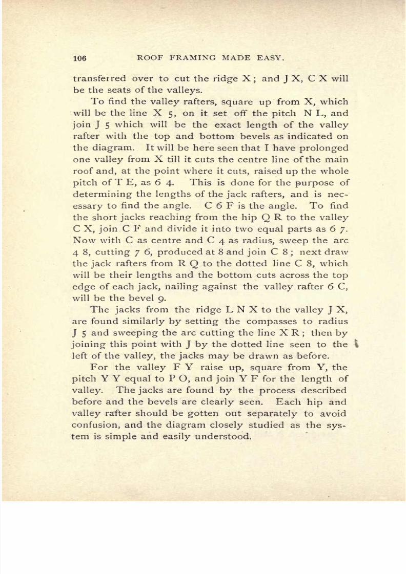
7/25/2019 Roof Framing Made Easy 1903
http://slidepdf.com/reader/full/roof-framing-made-easy-1903 108/174
106
ROOF FRAMING
MADE
EASY.
transferred
over
to
cut the
ridge
X;
and
J
X,
C
X
will
be
the
seats of
the
valleys.
To
find
the
valley
rafters,
square
up
from
X,
which
will
be
the
line
X
5,
on
it
set
off
the
pitch
N
L,
and
join
J
5
which
will be
the
exact
length
of
the
valley
rafter
with
the
top
and
bottom
bevels as indicated
on
the
diagram.
It
will
be
here seen
that
I
have
prolonged
one
valley
from
X
till it
cuts the centre
line
of
the main
roof
and,
at
the
point
where
it
cuts,
raised
up
the
whole
pitch
of
T
E,
as
6
4.
This is done
for
the
purpose
of
determining
the
lengths
of
the
jack
rafters,
and
is nec-
essary
to
find
the
angle.
C 6
F
is
the
angle.
To find
the
short
jacks
reaching
from
the
hip
Q
R
to
the
valley
C
X,
join
C
F
and divide
it
into two
equal
parts
as
6
7.
Now
with C
as
centre
and
C
4
as
radius,
sweep
the
arc
4
8,
cutting
7
6,
produced
at
8
and
join
C
8
;
next draw
the
jack
rafters from
R
Q
to
the
dotted line
C
8,
which
will
be
their
lengths
and
the
bottom cuts
across
the
top
edge
of
each
jack,
nailing against
the
valley
rafter 6
C,
will
be
the bevel
9.
The
jacks
from
the
ridge
L
N
X
to
the
valley
J
X,
are
found
similarly
by
setting
the
compasses
to radius
J
5
and
sweeping
the
arc
cutting
the line
X
R
;
then
by
joining
this
point
with
J
by
the
dotted
line
seen
to
the
i
left
of
the
valley,
the
jacks
may
be
drawn as before.
For the
valley
F
Y
raise
up,
square
from
Y,
the
pitch
Y
Y
equal
to
P
O,
and
join
Y
F
for
the
length
of
valley.
The
jacks
are found
by
the
process
described
before and
the
bevels are
clearly
seen.
Each
hip
and
valley
rafter
should
be
gotten
out
separately
to
avoid
confusion,
and the
diagram
closely
studied
as
the
sys-
tem
is
simple
and
easily
understood.

7/25/2019 Roof Framing Made Easy 1903
http://slidepdf.com/reader/full/roof-framing-made-easy-1903 109/174
ROOF
FRAMING
MADE
EASY.
1.07
CHAPTER
XXIV.
To Frame a
Roof
of
Unequal
Lengths
of
Rafters.
Let
A
B C
D
in
Fig.
67
be
the
square
plate
or
lower
plate,
which
has
short,
or
curb
rafters
supporting
a
cir-
cular
plate,
E F
G
H,
on which rests
a
drum,
or short
cylindrical
tower as
E
C
D
F,
Fig.
69,
topped
by
a
roof
Fig.
67.
PLAN
OF PLATES AND
RAFTERS.
with
curved
rafters.
By
referring
to
the
plan,
Fig.
67,
it will
be
seen
that
the
seats
of
the
rafters
will
be
of
dif-
ferent
lengths,
increasing
from the
centre,
or
number
6,
to the
corner
or
hip
rafter
2,
and
that
this occurs
on all
four
sides
of
the
square
plate.
As
the seats
are of
differ-
ent
lengths
the rafters
will
also
be
of
different
lengths,
though
they
have
the
same rise
or
pitch,
as
X
Y
in
Fig.

7/25/2019 Roof Framing Made Easy 1903
http://slidepdf.com/reader/full/roof-framing-made-easy-1903 110/174
108 ROOF FRAMING
MADE
EASY.
68. In
this
figure
the
different
lengths
of
rafters
will
be
distinctly
seen
decreasing
in size
from
the
hip
or
angle
X
Fig.
68.
DIFFERENT LENGTHS OF
RAFTERS.
to
the
centre
of
the
plate,
this
occurring
on
each
side,
which
will necessitate
8 sets
of
five
rafters,
cut
with
right
and
left
hand
bevels
on
the
plate,
also
one
set
of
Fig.
69.
PROJECTION
OF
ROOF
AND
DRUM.
4
with
square
cut
on
plate,
as
number
6.
Each
suc-
ceeding
rafter will
have
different
top
and
bottom
bevels,

7/25/2019 Roof Framing Made Easy 1903
http://slidepdf.com/reader/full/roof-framing-made-easy-1903 111/174
-
ROOF
FRAMING
MADE
EASY.
109
and
require
great
care
in
laying
out,
so
as
to
cut the
timbers
without
waste,
so
that
it
would be wisest
to
lay
out
and
cut them
in
sets,
one for
each side.
The
top
and
bottom
cuts,
as
represented
in
Fig.
69,
are
also
notched
to
fit
over
the
plates
and thus
prevent
their
slipping
;
this
will also
demand
care
in
laying
out,
be-
cause
each notch
will have
a
different
bevel.
The
gothic
roof
on
the
drum
may
be
struck
out
to
the
curve
shown
and
rafters
cut out.
As
all
the rafters
are
the same
length,
they
can be sawn
from one
pattern,
and
set
up
in
the
manner
which
I
have
already
described.

7/25/2019 Roof Framing Made Easy 1903
http://slidepdf.com/reader/full/roof-framing-made-easy-1903 112/174
110
ROOF
FRAMING
MADE
EASY.
CHAPTER
XXV.
To Frame
a
Roof
with
Pitched
Ridges.
The
following
roof
of
an
unusual
kind
will
be
found
of
value
to
those
carpenters
who
live
in
the
country
or
whose
duty
it
is
to
construct
barns,
or other
special
buildings,
where
great
room is
required
in
the
roof
or
attic.
Fig.
70.
GENERAL
APPEARANCE
OF
ROOF.
The
engraving,
Fig.
70,
is
an isometric
view
of
the
roof,
and
as will be
seen
it
consists
of
a roof
of
four
gables
on
a
square
plan,
with
four
valleys
and
four
ridges
which
rise on
a
pitch
from the
peaks
of
the
gables
and
terminate
at
the
peaks
of
the
valleys,
giving
the

7/25/2019 Roof Framing Made Easy 1903
http://slidepdf.com/reader/full/roof-framing-made-easy-1903 113/174
ROOF FRAMING
MADE
EASY.
Ill
effect
as
shown.
The
rafters
of the
gables
are
half
or
mitre
pitch,
or
twelve
and
twelve
on the
steel
square.
The
peak
of
the
valleys
represented
in
Fig.
71
is
4
feet
higher
than
the
gable
peaks
so that
the
ridges
rise
on
pitch
in
the
manner
shown
in
the
cross
section
Fig.
71,
thus
forming
a
very peculiar
and
unusual
form
of roof.
In
order
to
frame
this
roof
in
the
simplest
manner
proceed
to
Fig.
72,
and
let
A
E
B
H
D
C
be
the
plan
of
the
roof A
F,
B
F,
D
F
and
C
F,
being
the
seats
of
the
valleys.
E
F,
H
F,
G
F,
and
I
F,
being
the
seats
or
plans
of the
hips.
To
find
length
of
valley
from F
Fig.
71.
VALLEYS,
RAFTERS
AND RIDGES.
square
up
at
F,
A
J,
equal
in
height
to
A
C
Fig.
71,
and
join
J
C,
Fig.
72,
for
the
lengths
and
bevels
of
the
four
valley
rafters.
Now for
the
eighteen jack
rafters
the
author
has
found
it most convenient
to
develop
the
roof
in
order
to
prove
the
accuracy
of the
layout
;
there-
fore
on
C
G
D,
erect
one
gable
to
stand
over C
G
D,
as
C
K
D.
From
D,
make
D
M,
equal
in
length
to C
J,
and
K
M,
equal
in
length
to
the
ridge
E
C,
or
C
F,
Fig.
71.
Divide off on
KM,
Fig.
72,
the
jack
rafters
and
draw
them
parallel
to
K
D,
in
the
way
illustrated at
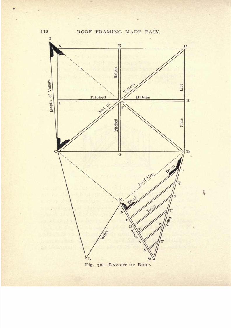
7/25/2019 Roof Framing Made Easy 1903
http://slidepdf.com/reader/full/roof-framing-made-easy-1903 114/174
112
ROOF
FRAMING
MADE
EASY.
Fig.
72.
LAYOUT
OF
ROOF.

7/25/2019 Roof Framing Made Easy 1903
http://slidepdf.com/reader/full/roof-framing-made-easy-1903 115/174
ROOF
FRAMING
MADE
EASY.
113
Fig.
72,
as
N
O,
P
Q,
R
S,
T
U,
V
W,
and
X
Y.
The
bevels
at O
and
N,
Fig.
72,
will
be
the
side
bevels
against
the
ridges
and
valleys, being
reversed
for
differ-
ent
right
and
left
sides,
the down
or
vertical
cut
of
the
bottom ends
of
the
jacks
nailed
against
the
valley
sides
will
be as
the
pitch
of
the
valleys
and
the
top
cuts as
that
of
the
gables
or
mitre
cut.
To
prove
the
accuracy
of
the
methods,
first
draw
the
engraving
on
cardboard
and
then
cut out as
follows
:
Cut
out
the whole
plan,
AEBHDMKLCA;
then
make
a
slight
cut with a
pocketknife
from
C to
K,
and
from
K
to
D,
also
across
C
G
D.
Fold over
the
development
until K
is
over
G
D
M,
is over
D
F
;
C
L
over C
F
;
and L
and
M
joined
together,
are over
F,
with
the
ridge
L
K over
G F.

7/25/2019 Roof Framing Made Easy 1903
http://slidepdf.com/reader/full/roof-framing-made-easy-1903 116/174
114
ROOF
FRAMING
MADE
EASY.
CHAPTER
XXVI.
To
Frame
a
Round-House
Roof.
Assume
the roof
to
be
semi-circular
in
plan
as
rep-
resented in
Fig.
74,
and
to
have
a
pitched
roof with
a
ridge,
the
pitch
being
half,
or 12
and 12
on
the
steel
square,
as
seen
at
D G
F,
Fig.
74,
where
the
lengths
of
the
rafters
and
bevels
are
delineated.
ABC
and
D E
F,
are
the
gables
on
the
plan Fig. 74
seen
on the
eleva-
tion
Fig.
73,
with windows
and
doors
in same.
In order
ft
to
find
the
length
of
the
common rafter
simply
raise
up
from
E,
Fig.
74,
the
pitch
or
rise
E
G
and
join
D
G.
As
the outer
plate
line
A
X
F,
is much
longer
than
the
inner
plate
line C
Z
D,
more
rafters will
be
required
so
as to
form
a
sufficient
support
for
the
roof boards
and
covering.
For
this
reason
an
extra
rafter
from
the
plate
line
A
X
F,
to
the ridge
B
K
I
E
must
be
inserted
be-
tween
each
abutting
rafter
so
as
to
equalize
the
spacing
and
obtain
a
stable
roof. The
proper
way
to
find
the

7/25/2019 Roof Framing Made Easy 1903
http://slidepdf.com/reader/full/roof-framing-made-easy-1903 117/174
ROOF
FRAMING
MADE
EASY.
115
shape
of the
roof
boards
is
seen
at
the
bottom
side
of
Fig.
74.
Divide
D
H
into
10
equal
parts,
or
more
if
desired,
then with
O,
as
centre
and
O
I,
as
radius,
de-
scribe
a
curve,
similarly
describe
curves
from
D,
2,
3, 4,
5
6,
7,
8,
9
and
10,
which will
of
course
bring
the
boards
up
to
the
ridge
line.
Now
take the
distance
Fig.
74-
from
E
to
I
and
set it
off
from
H
to
P,
the centre
of
the
rafter
at
I,
and
this
will
give
the
lengths
of
boards for
one
section.
A
like
method can
be
followed for
cover-
ing
the outside
slope
of
the
roof.
This roof
is
of a
very
rare kind
and
is
only
found
on
railroads
where
.locomo-
tives
are
stored or
on
large
estates
for
barns
or
out-
houses.

7/25/2019 Roof Framing Made Easy 1903
http://slidepdf.com/reader/full/roof-framing-made-easy-1903 118/174
116
ROOF
FRAMING
MADE
EASY.
CHAPTER XXVII.
Framing
a
Cantilever
Roof.
In
answer to
a
letter
requesting
me to
illustrate
and
describe a
cantilever
roof,
I
submit
for the benefit
of
all
students
of
carpentry
the
following design
for
a
roof
of
this
description,
which will be
adaptable
either
for
a
large
shed or
station.
The
engraving,
Fig. 75,
shows
a transverse
or
cross
section
of
the
shed,
which
may
be
any
length
desired,
the
width
(covered)
shown
is
48'
o ,
at
a
scale of
l
/&
inch
=
I
foot.
If
the width
be reduced
half,
timbers
half
the
width
and
thickness
given
here
will be sufficient.
The
height
to under
side
of
straining
beam
is
13'
o ,
to
ridge
26'
6 .
The
construction
of this
building
is
very
simple
and
is
fully
illustrated
by
the
drawing.
It
con-
sists
of a
series of
concrete
footings
about
3
feet or
4
feet
square,
placed
on sand
or
hard
clay
24'
o
apart,
measuring
from
centre
to
centre
across;
and
10'
o
apart,
measuring
from
centre
to
centre,
longitudinally
or
lengthways.
On
top
of
these
footings
is
set
a
good
blue
or
granite
stone
mortised
out
to
receive the
bottom
ends of
the
posts
or
uprights.
These details constitute
the foundation.
The
frame
superstructure
primarily
consists
of
the
series
of
10
x
10
yellow
pine
square
posts,
which
are
tenoned at
top
and
bottom
ends,
at
the
bottom to
fit
into the bottom
stone
and at
the
top
to
receive the
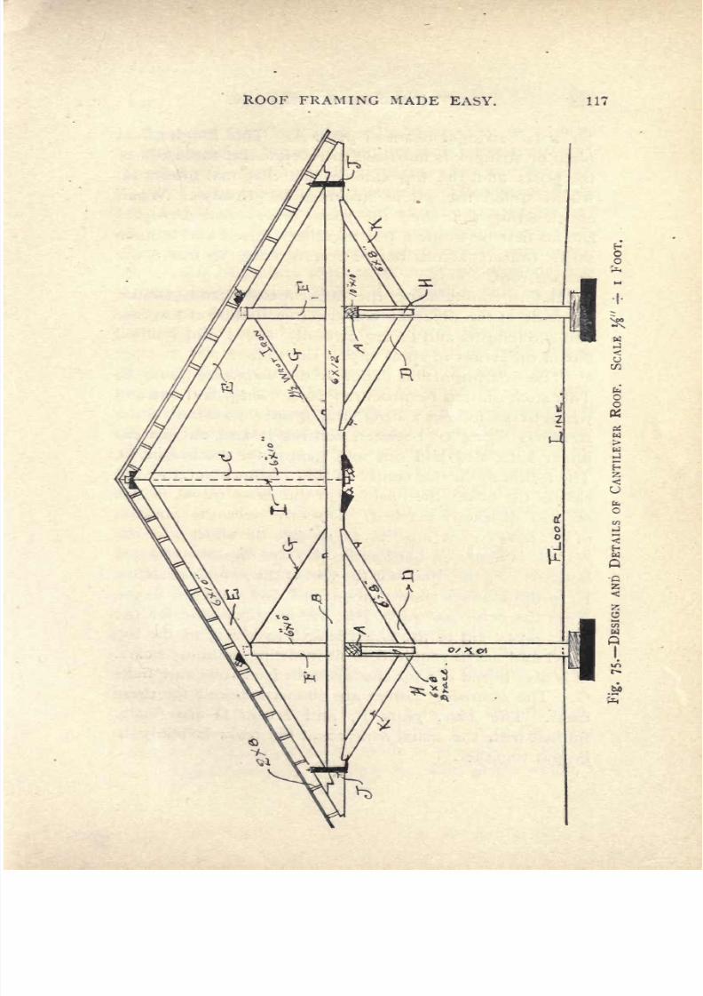
7/25/2019 Roof Framing Made Easy 1903
http://slidepdf.com/reader/full/roof-framing-made-easy-1903 119/174
ROOF
FRAMING
MADE
EASY.
117

7/25/2019 Roof Framing Made Easy 1903
http://slidepdf.com/reader/full/roof-framing-made-easy-1903 120/174
118 ROOF FRAMING MADE EASY.
10 x
10
stringer
beam
or
plate
A.
This
longitudinal
plate
or
stringer
is
mortised
to receive the
top
ends
of
the
posts
and
the
top
ends
of
the
diagonal
braces
H,
which
stiffen
the
whole structure
lengthways.
When
constructing
this
shed
the
posts,
braces
and
stringers
should first be
framed,
put
together,
raised
and
tempo-
rarily
braced
across
before
commencing
to
frame the
trussed
roof.
Before
commencing
the
latter
a
close
study
should
be made
of the
different constructive details
of
the roof
and
the
lengths
and forms
carefully
noted
and
studied
out
in
order not
to
spoil any
of the
timber.
The first
important
detail
is the
straining
beam
B.
This stick
should be
procured
50'
o
long,
laid out
and
wrought
as follows
:
First,
the
proper position
of
the
stringers
A,
24' o
between
centres
is
laid
out
on
the
under
side,
also
laid
out
and
gained
for
the
braces
D.
Then
directly
in
the
centre
of
this distance
on.
the
top
side
of the
beam,
the
position
of
the
king
tie
C,
is
laid
off
and
distinctly
marked.
Directly
over
the
position
of
the
stringers
a
mortise
to
receive
the
short
6 x 10
posts
F
is
made
on both
ends,
also
the
opposite
ends are
notched
or
gained
out
for
the
feet
of
the
principal
rafters
E,
in
the
manner
shown,
about
2 down
in
the
beam,
i
Next
the
principal
rafters
E,
are mortised
out
for the
short
posts,
cut
to
the
exact
length
as
given,
to
the
top
bevel
and
notch
required
to
fit
into
the
straining
beam.
It
is
also
bored
out
for
the
wrought
iron
rods and
bolts
G.
The
straining
beams
are
likewise
bored
for
these
irons.
The
short
posts
F,
and
braces
D
are
finally
framed
with
the usual
tenons
and the
truss
is
ready
to
be
put
together.

7/25/2019 Roof Framing Made Easy 1903
http://slidepdf.com/reader/full/roof-framing-made-easy-1903 121/174
ROOF
FRAMING
MADE
EASY.
119
In
doing
this
the
proper
way
to
proceed
is
to
first
set
the
straining
beam
B,
then to insert
the
tenons of
the
short
posts
F,
into their
mortises,
next
the
king
tie
C,
and
finally
the
principal
rafters
E.
The
vertical
bolts
I,
and
washers
are
next
inserted
and
the
straps
J
put
on.
This
operation
must
of course be
gone through
on
each
truss,
and
the
whole
number
finished before
commenc-
ing
to
raise
them
into
their
permanent position
on
top
of
the
stringer
beams
AA.
The
raising
can be
done
with
a
good gin pole
or
derrick.
When the
trusses
are
set
vertically
on
stringers
AA,
to
form the
appearance
seen
in
the
engraving,
directly
over the
posts
below,
each one
should
be
well
braced
with
2 x
4
joists
to
prevent
it
from
being
blown
or
knocked down. Each
truss
should
also be set
perfectly
plumb sideways.
If
desired,
the
outer
braces
KK
may
be
omitted
and
the
wrought
iron
rod
G
inserted
to
counterbalance the
over-
hanging
portion
of
the roof.
The
space
inside the
braces
may
also
be
filled
in
with
ornamental
scroll
work,
either
in iron or
wood. In
regard
to
the
strains on
the
different
timbers
I
would
say
that
the
straining
beam
B
is
in
tension,
the
braces
K
and
D
underneath to
the
posts
are
in
compression.
The
principal
rafters
are
in
compression.
The
king
tie
C is
in
compression
and
the
purlins
bear
a
lateral strain across
the
fibres. The
bolts
are
wrought
iron. The
washers and
plates
cast iron.
Straps
are
of
wrought
iron
j
x
2 .
This
roof
may
be
safely
covered with
shingles,
or
metal
shingles,
or
tar
paper.
It
will
be
noticed
that
I
have
given
in
this
descrip-
tion
a
full
written
and
detailed
description
of
the
con-
struction
of
this roof and
mode
of
procedure
neces-
sary
to
be
followed
in
building
it.
The
years
which
I
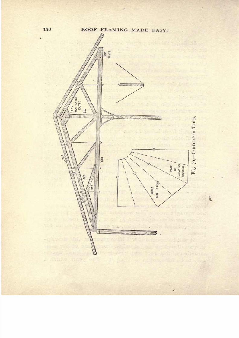
7/25/2019 Roof Framing Made Easy 1903
http://slidepdf.com/reader/full/roof-framing-made-easy-1903 122/174
120
ROOF
FRAMING
MADE
EASY.

7/25/2019 Roof Framing Made Easy 1903
http://slidepdf.com/reader/full/roof-framing-made-easy-1903 123/174
ROOF
FRAMING MADE
EASY.
121
have
studied construction
have
taught
me
that
much
detailed
information
is
never
superfluous
in
conveying
accurate
mechanical
practice
to
others.
The
truss
illustrated
at
Fig.
76
was
designed
by
Walter
P.
Rice,
C.
E.,
of
Cleveland,
Ohio,
for
the roof
of
the
grand
stand
at
the
baseball
park
in
that
city,
and
reflects
great
credit
on
him
for
the economical
manner
in
which
he
disposed
of
the
constructive
details
in
such
a
way
as
to
leave
an
unobstructed
view
of
the
field.
As
will be
seen
on
reference to the
plan
the
portion
of
the
roof
where
the
cantilevers
were
employed
covered
the
portion
on
the
corners
which
was
contained
in
the
two
sides
placed
at
right angles,
and had
a
post
been
placed
under
each
truss
the
view
of
the
field
would have
been
much
intercepted.
To
avoid
this
he
suspended
the
in-
tervening
trusses
shown
by
the
dotted
lines
on
the
plan
on
iron
rods
which
were
carried over
those trusses
rest-
ing
on
the
posts,
thus
leaving
the
space
below clear
for
the
spectators
to
see the
players.
These trusses
are
but
slightly
different
in
form
from
those
in
ordinary
roofs,
though
the
static
conditions
are
changed
on
account
of
the
cantilever
form. The
drawing
will
explain
to
read-
ers
its
form
and
show
how
judiciously
and
economically
the
pieces
were
proportioned,
also how
the
engineer,
realizing
by
calculation
that
the
greater
part
of the
ver-
tical
strain
would
necessarily
be exerted
on
the
front
columns,
increased the
efficiency
by
using
iron
posts
of
the
diagonal
lattice
pattern
of
the
proportions
shown.
The
idea
is
an
excellent one
and
worthy
of
the
high
reputation of
its
designer.
It
need
scarcely
be
added
that
the
entire
workmanship
of the
whole construction
of
the
stand,
mostly
timber,
was done
in
the most
cred-
itable
manner.

7/25/2019 Roof Framing Made Easy 1903
http://slidepdf.com/reader/full/roof-framing-made-easy-1903 124/174
122
ROOF
FRAMING
MADE EASY.
CHAPTER
XXVIII.
To Frame
a
Roof
with
an
Elliptic
Plan
and
Straight
Ridge.
Readers
will
find
in this
chapter-
a roof
which
is
of
unusual
shape
and
entirely
different
from
the
forms
gen-
erally
found
on
ordinary
buildings,
and
though
this
form
of
roof is
not
by
any
means
original,
I
have never
yet
seen
its
lines
or
laying
out
published,
even
in
the
most
advanced
works on
carpentry
or
building
construction.
I
have no
doubt,
therefore,
that the
advanced student
of
framing
will
find
in
it
something
worthy
of
his
at-
tention.
Coming
then
to
a
consideration
of
our
roof we
find
that
its
plan
or
plate
as seen
at
Fig. 77,
is
elliptical,
as
o,
i,
2,
3,
4,
5,
6,
7,
etc.
The
length
or
major
axis
of
the
roof
plan
o
20 is
16
feet,
and
its
width
on
the
minor
axis
is
8
feet.
The
ridge
is
8 feet
long.
The
21
rafters
radiate,
and
are
spaced
2
feet
on
centers
on
the
wall
plate
and are
similarly
divided
up
on the
ridge.
The
rafters
od,
and
20
b,
on
the
plan
are
A
B,
and
C
D,
on
the
elevation above
and
each
line,
as
I
c,
on
plan
is
rep-
resented
by
a
sloping
line
of
the
elevation.
I
would
here state that each
line
as
delineated
simply
indicates
the centre
line
of
each
rafter so that
the
measured
depth
and
thickness
must
be
placed
to
the
right
and
left
sides
of
this line.
The
dotted
lines
to
the left
conveying
the
points
on

7/25/2019 Roof Framing Made Easy 1903
http://slidepdf.com/reader/full/roof-framing-made-easy-1903 125/174

7/25/2019 Roof Framing Made Easy 1903
http://slidepdf.com/reader/full/roof-framing-made-easy-1903 126/174
124
ROOF
FRAMING
MADE
EASY.
the
plate
on
plan
to the
same
on
the
elevation,
will
show
how
they correspond,
and
I
would
draw
similar
dotted
Fig.
78.
lines
from
the
ridge
on
plan
to
the
ridge
on elevation
where
it is
not
liable to
confuse
the
diagram
and
render
it
difficult
to
understand.
The
plan
shows the seat
or

7/25/2019 Roof Framing Made Easy 1903
http://slidepdf.com/reader/full/roof-framing-made-easy-1903 127/174
ROOF
FRAMING
MADE
EASY. 125
plan
of
each
rafter,
and
the
elevation its
exact
position
when
raised.
In
order
to
obtain the neat
length
of each
rafter
a
long
and tedious method
must
be
resorted
to.
This
i^\\\\\\\Y\\\N
\A
\
\\VA\\\\
\
\
ii^\v'vCx\;\
\\
\\
\ \ \ \ \ \ \
\
\ \
\ \**
Fig.
79-
consists
in
raising
up
on each
seat from
the
ridge
at
right
angles
to
the
seat,
the
full
pitch
of
each
rafter
on
a
perpendicular
line
from
the
major
axis,
as
c
f\
d
g,
and
e
h.
Then
join
h
16,
g
15,
and/
14,
on
the
perip-
7/25/2019 Roof Framing Made Easy 1903
http://slidepdf.com/reader/full/roof-framing-made-easy-1903 128/174
126
ROOF FRAMING
MADE
EASY.
hery
or
plate,
which
will
give
the neat
length
of
the
rafters
which
will stand over the
seats
c
14,
d
15,
and
e
16,
with
their
required top
and
bottom
bevels,
repre-
sented
in
the
engraving.
This
same
process
must be
done
for
all
the
rafters to
the
right
of
the
center line
from
10
to
20;
and
a
similar
set
must
be
laid
out
for
the
left
side
on
the
bottom,
to
space
round
from
o
to
x.
In
a like
manner the
set
from
10
to
o
will
require
to
have a
duplicate
set
to be
spaced
out
from
x to
20.
The
bottom
bevels
at
the
plate
and
top
bevels at
ridge
will likewise be
of a
different
cut
for
each
rafter,
and
will
be
right
and
left handed
for
opposite
sides.
The
sides
of
the roof will be twisted
but
not
ungraceful,
and
the
laying
out
will be found to
be
very
slow and
tedi-
ous,
requiring
great
care,
close
attention and
accuracy.
Coming
now
to
the
manner
of
covering
this
roof,
I
would state that this
might
be
done in
either of
two
ways
:
First,
by
boarding
it
vertically
;
or
second,
by
boarding
it
horizontally.
If
the
first
method is
adopted
every
second
rafter
may
be
omitted,
and
elliptic
sweeps
corresponding
to
each
ellipse
as
the
roof
diminishes to
the
top,
will
require
to be
gotten
out
and
nailed
in
from
the
plate
to
the
ridge.
These
will
need
to
be
sawn
out
to
the several
sweeps
seen
in
Fig. 78,
which
will
each
require
to
be struck
from
each
major
and
minor
axis,
according
to
their
diminution
as
they
decrease
in
width
from
A
to
J,
at
Fig.
78.
When
the
sweeps
are
found
the
diminishing
cover-
ing
boards
will be almost
similar
to the
centre
lines
of
the
rafters,
as
laid
down
at
Fig.
77,
the
widths
of the
top
and
bottom
ends
being
equal
to
those shown
on
the

7/25/2019 Roof Framing Made Easy 1903
http://slidepdf.com/reader/full/roof-framing-made-easy-1903 129/174
ROOF
FRAMING
MADE
EASY. 127
plan,
and
the
length
or
height equal
to the
lengths
of
the
rafters.
If it be
the
preference
of
the
carpenter
to
cover his
roof
horizontally
I
would recommend
him
to
follow the
method
which
I
illustrate
at
Fig.
79,
where
A
B
C
D
is
the
original
elevation
of
the
roof and
A D
the
major
axis
of
the
plate,
E
F
being
the
major
axis
of
the
top
edge
of the
first
semi
ellipse
covering
board.
A
D
be-
ing
the
major
axis
of
the bottom
edge.
To
obtain
the
covering
boards
produce
E
B
and
F
C
to
P,
and divide
the
semi-
ellipse
E
Q
F,
into twelve
equal
parts. Join
each
division
point
with
P,
and
draw
from
each
down at
right
angles
to
E
F,
cutting
E F
at
b,
c,
d,
e,
f,
g,
h
y
i,j>
k>
I-
With
the
centre
P,
through
b, c,
d,
e,f,
etc.,
draw
b
M,
c
N,
d
O,
e
P,/Q,
g
R,
//
S,
/
T,/U,
k
V,
and
/W,
cutting
A
D,
in the
points
M, N,
O,
P,
Q,
R,
S,
T,
U,V,W.
From
these
points
draw
lines down
perpen-
dicular
from
A
D,
cutting
the
semi-ellipse
A
X
D.
Now
to
obtain
the
curve
of the
covering
board
which
will
bend
over
A
E
F D. From
P
draw
P
Z,
square
to
P
C,
and
make
P
Y
equal
to
/
I,
at
elliptic
curve.
Make P
V
equal
to
k
2,
and so
on
up
to
g
Q.
Next
with
F
as
cen-
tre
and
F
i
as
a
radius
describe the
arc
at
F,
and
from
Y,
at
top,
draw
Y
A',
tangent
to the
arc.
Similarly
from
V,
and
with
a
similar
arc draw
V B
7
,
and
so
on
to
Z
F'.
Draw
through
the
points
where
the arcs are
tangent
to
the
lines to obtain
shape
of
top
curve for
covering
board.
When
the
centre
point
is
reached,
describe
the
semi-
circle
P
X,
at
top
and
proceed
as before.
Next set off
the
dis-
tance
F
D,
down
from
the
curve
F
B
2
which
will
give the
curve
for
the bottom
edge.
This
process
must
be
fol-
lowed
out
for
every
board to
the
top by
laying
out the
7/25/2019 Roof Framing Made Easy 1903
http://slidepdf.com/reader/full/roof-framing-made-easy-1903 130/174
128
ROOF
FRAMING
MADE
EASY.
minor and
major
axes
of each
ellipse
at
horizontal
line,
as seen
on
Fig.
78,
so
as
to
get
them
the
right shape.
All
boards
should
be
thin so
as to
bend
round
the
ellipse
and
be
very
carefully
and
accurately
laid
out.
To
re-
tain the
nails
for
slate
or
shingle
a
double
thickness
of
boards
may
be
laid
on.

7/25/2019 Roof Framing Made Easy 1903
http://slidepdf.com/reader/full/roof-framing-made-easy-1903 131/174
ROOF
FRAMING
MADE
EASY.
129
CHAPTER XXIX.
Church
Roof
Construction.
It
has
often
been
said
that,
there
is
nothing
new
under
the
sun, and,
judging
by
the continual
repro-
duction
of
old,
well known
and
comparatively
simple
details
of
building
construction,
it
is
positively
refresh-
ing
to
come
across
something
which is out
of
the
ordi-
nary,
or
which
shows inventive
and
constructive
skill.
I
have
no
doubt,
therefore,
but that
those
readers
who
have
an
eye
to
progress
and
the
development
of
new
constructive
details
of
carpentry
will welcome
the
un-
usual
form of
trussed
roof which
I
illustrate,
and
which,
as
far as
I
can
learn,
has
never
before
been
so
arranged.
To
commence,
I
would
state that
this roof
covered
the
auditorium
of
a
small
chapel,
about
50
feet
long
and
20
feet
wide
in
the clear
of
the walls.
The
roof
might
be
placed
among
the
open
tim-
bered
class,
though
it
is
not
entirely
open,
inasmuch
as
only
half
of
its
construction
is seen
from
below,
which
will
be
seen
by referring
to
Fig.
80,
the
cross
sec-
tion
of
the
roof,
showing
its
construction
in its
entirety,
and
which,
with
Fig.
8
1,
is
explained
as
follows :
A,
A,
are
the
principal
rafters,
which are
constructed of
two
pieces
of
yellow
pine.
The bottom
piece
is
curved on
the
soffit
side
and
joined
to
the
bottom end
of
the
upper
straight
part
by
being
dowelled and
bolted
from
the
up-
per
side,
the
I
inch
dowels
being
on
the
top
and bottom

7/25/2019 Roof Framing Made Easy 1903
http://slidepdf.com/reader/full/roof-framing-made-easy-1903 132/174
130
ROOF
FRAMING MADE
EASY.
Fig.
80,
CROSS SECTION.
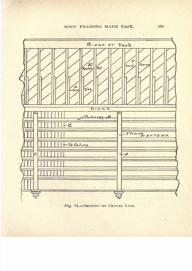
7/25/2019 Roof Framing Made Easy 1903
http://slidepdf.com/reader/full/roof-framing-made-easy-1903 133/174
ROOF
FRAMING
MADE
EASY.
131
/
fytt
/
7
,
^7-7?
^^'3
ni
Fig.
81.
SECTION
ox CENTRE
LINE.
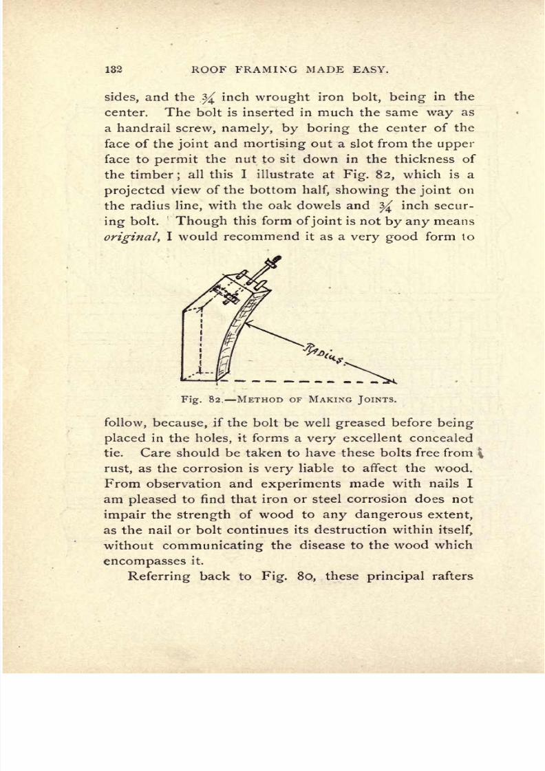
7/25/2019 Roof Framing Made Easy 1903
http://slidepdf.com/reader/full/roof-framing-made-easy-1903 134/174
132
ROOF
FRAMING
MADE
EASY.
sides,
and the
^
inch
wrought
iron
bolt,
being
in
the
center.
The
bolt
is
inserted
in
much
the
same
way
as
a
handrail
screw,
namely, by
boring
the
center
of
the
face
of
the
joint
and
mortising
out a
slot
from
the
upper
face
to
permit
the
nut
to sit
down
in
the
thickness
of
the
timber
;
all
this
I
illustrate at
Fig.
82,
which
is
a
projected
view of the
bottom
half,
showing
the
joint
on
the
radius
line,
with
the
oak
dowels
and
^
inch secur-
ing
bolt.
Though
this
form
of
joint
is
not
by
any means
original,
I
would
recommend
it
as
a
very
good
form
to
Fig.
82. METHOD
OF
MAKING
JOINTS.
follow, because,
if
the bolt
be well
greased
before
being
placed
in
the
holes,
it
forms
a
very
excellent
concealed
tie.
Care
should be
taken
to
have
these bolts free from
rust,
as
the
corrosion
is
very
liable
to
affect
the
wood.
From observation
and
experiments
made with
nails
I
am
pleased
to
find
that
iron
or
steel
corrosion
does
not
impair
the
strength
of
wood to
any
dangerous
extent,
as
the
nail
or
bolt
continues
its destruction
within
itself,
without
communicating
the
disease
to the
wood which
encompasses
it.
Referring
back
to
Fig.
80,
these
principal
rafters

7/25/2019 Roof Framing Made Easy 1903
http://slidepdf.com/reader/full/roof-framing-made-easy-1903 135/174
ROOF
FRAMING
MADE
EASY.
133
A
A,
will
be found
to
be
notched
out
at
the
peak
or
upper
end
fo
receive
the
ridge,
the
top
edge
of
which
comes
fair with the
top
edges
of
the
principal
rafters.
The
purlins
B,
seen in
Figs.
80
and
81,
are notched
into
the
sides
of
the
principal
rafters
so
as likewise
to
be
flush
with
their
top
edges,
which
will
be
seen to the
left
of
the
engraving.
On
the
top
edges
of
these
purlins
is
laid
2^/2
inches
matched
and
V
edged
Tfe
inch
ceiling
laid
face side
down,
to a
close
joint,
the
butt
joints
be-
ing
broken
on
the
purlins,
thus
rendering
them
invisible
from below.
From
this
up
a
rather unusual
form
of
roof construc-
tion
is
adopted
Reference to
the
feet
of
the
high
pitched
rafters
will
show
that
they
do
,not
rest
on
any
wall
plate
in the
usual
way,
but
are
bracketed
so
as
to
be
self
supporting
on
two
cleats,
one
set
vertically
and
the other
horizontally.
The cleats
being solidly spiked
to
the
sides
of the
Cross
ties
rendering
them
perma-
nently
fixed.
The
cross
ties
support
the
high
pitched
rafters
at their
upper
end
by resting
on
the
point
K,
thus
forming
from
K
to
P,
a
sort of
modified
cantilever.
These resist
a
double
pressure
which
I
denote
by
the
directions
of the
arrows
in
Fig.
80.
The
high pitched
rafters
are
spaced
1
2
inches
on
centers
and each is
pro-
vided with
a
cross
tie or
lower
rafter,
which
of
course
are
similarly
spaced,
lying
with
their bottom
edges
on
the
upper
side of
the
J^
inch
ceiling
which
is
nailed on
the
purlins.
These
ties are toe-nailed at intervals
into
the
purlins,
so
as
to
secure them
firmly,
and
tie
the
whole
roof
together.
The
outside
roofing
under
the
slate
is
laid
diagonally
as
represented
at
Fig.
8
1
.
Roofs
of
this
description
will
require
to
be laid out
full
size
in

7/25/2019 Roof Framing Made Easy 1903
http://slidepdf.com/reader/full/roof-framing-made-easy-1903 136/174
104
ROOF
FRAMING
MADE
EASY.

7/25/2019 Roof Framing Made Easy 1903
http://slidepdf.com/reader/full/roof-framing-made-easy-1903 137/174
ROOF
FRAMING
MADE
EASY.
135
order
to
get
all
the
joints
exact,
and
the
tirrbers
framed
to their neat
lengths.
I
would
in
conclusion
advise
readers to
make
a
close
study
of
this
roof and
endeavor
to evolve new ideas
from what it
suggests.
I
am
of
the
opinion
that
there
is no limit
to
the
direct
application
of
the
cantilever to
all
descriptions
of
timber
framing,
and
a
careful examination
of
the
qualities
of
timber,
com-
bined with
a
judicious placing
of
the
constructive
parts,
will
aid
in
producing
new
ideas
in
modern
carpentry.
The
following description
of
a
very
fine
specimen
of
a
gothic
trussed roof
will be found
very
interesting
by
those
carpenters
who
make
a
study
of
constructive
fram-
ing
inasmuch as
it
embodies
some
features
not
usually
found
in
roofs of
this
class.
I
feel
sure,
therefore,
that
it
will
be
appreciated.
The roof
is
in
the
city
of New
York
and
is
one
of
the
best
examples
of
American
car-
pentry
done
lately.
Reference
to
Fig.
83,
which is an elevation
of
half
of one
of
the
auditorium
trusses,
will
convey
a
general
idea
of
these
details which
are,
of
course,
the
main
parts
of
the
construction.
There are in
all
thirteen
of
these
of
32
feet
span,
with
two
of
larger
span
which have for
their
seats
the
diagonal
lines
of the
transepts
as
A
B,
Fig.
84,
where
I
show
a
sketch
outline
plan
of the
roof
with
the
seats
of the trusses
which
were
spaced
8 feet
on
centre.
Those
lines
marked
T
were
the
trusses.
Ridges
being
on
centre
lines
of
the
plan. Especial
care
was
necessary
in
laying
out
the
diagonal
trusses
as
I
will
explain
further
on.
Now
as
to
the construction
of
the transverse
trusses
we
will
proceed
to
analyze
one,
as
the thirteen
were
ex-
actly
alike,
so
that
a
full
description
of one
will
explain

7/25/2019 Roof Framing Made Easy 1903
http://slidepdf.com/reader/full/roof-framing-made-easy-1903 138/174
136
ROOF
FRAMING
MADE
EASY.
how
all
were
built,
so
referring
back to
Fig.
83,
readers
will
see
that
the
roof
was
made
up
of
two
10
x
14
prin-
cipal
rafters
28
feet
long
into
which
were
framed
from
the
soffit
side or
under
side
a
10
x 12 hammer
beam,
10
x
10
suspension
timber
and
two
10
x 10 struts
on
Fig.
84.
PLAN OF
ROOF
TRUSS.
each
side
respectively.
The foot
or
bottom
end of
each
principal
rafter
was
gained
and
tenoned into an
8
x 10
bracket
which
rested
on
the
wall
and
was
supported by
an
8
x
10
upright
and
a curved
brace
or
strut.
The
centre
of
the
hammer
beam
is
also
supported by
a
curved
brace or
strut
which
is
gained
and
tenoned
into
the
sus-
7/25/2019 Roof Framing Made Easy 1903
http://slidepdf.com/reader/full/roof-framing-made-easy-1903 139/174
ROOF
FRAMING
MADE
EASY.
137
pension
tie
and is
also
suspended
by
a
centre
king
post,
which
completes
the constructive
members. It
is
scarcely
necessary
for me to
say
that a
large
force
of
skilled
mechanics
were
employed
on
this
roof
as
the
different
members
required
a
great
deal
of
skilled
work-
ing
and
handling
especially
as the roof
was
of
yellow
pine
timber
finished
with
the
smoothing
plane
and
sand-
papered
for
varnishing.
In
order
to
comprehend
this
I
would
ask
readers
to
observe
the
projected
view
of
the
principal
rafter
which
I
illustrate
at
A,
Fig.
85.
Here
the
mortises
and
gains
for
the
strut
braces
and hammer
beam
are
shown
together
with
the
tenoned
ends,
top
and
bottom,
also
the
2x3
gains
sunk
in on
the back or
top
edge.
In
addition
to this
the
lower arrises were
stop
cham-
fered
down
^
of
an
inch
on
each
face
;
so
that
skilled
readers
will
appreciate
the
amount
of
framing
involved
on
twenty-six
timbers
of
this
kind.
The curved
struts
B,
Fig.
85,
also
involved
much
skilled
labor,
as
it would
be
obviously
impossible
to
make
a
timber of
this
curvature
of
one
piece
of
timber,
and even
were
it
possible
to
do
this the
stick would be
weak
on
account
of
the short grain
which
must
occur
if
it
were
gotten
out of one
piece
of
timber. It was
there-
fore
decided
to
build
these
pieces
on
the
laminated
system
;
or
in
simpler
words,
to build
it
up
in
thick-
nesses,
bending
each
thickness on
a
curved
mold
to
the
desired
curvature
shown
at
B. This
was
therefore
done
by
steaming
the
pieces
before
bending,
then
allowing
them
to cool
and
afterwards
gluing
and
nailing
them
together
to
make
up
the
whole
thickness.
When
dry
the
outer
right
and
left
faces
of
i^
stuff
were
glued
and

7/25/2019 Roof Framing Made Easy 1903
http://slidepdf.com/reader/full/roof-framing-made-easy-1903 140/174
138
ROOF
FRAMING
MADE
EASY.
Fig.
85.
CONSTRUCTIVE
FRAMING
OF
ROOF.
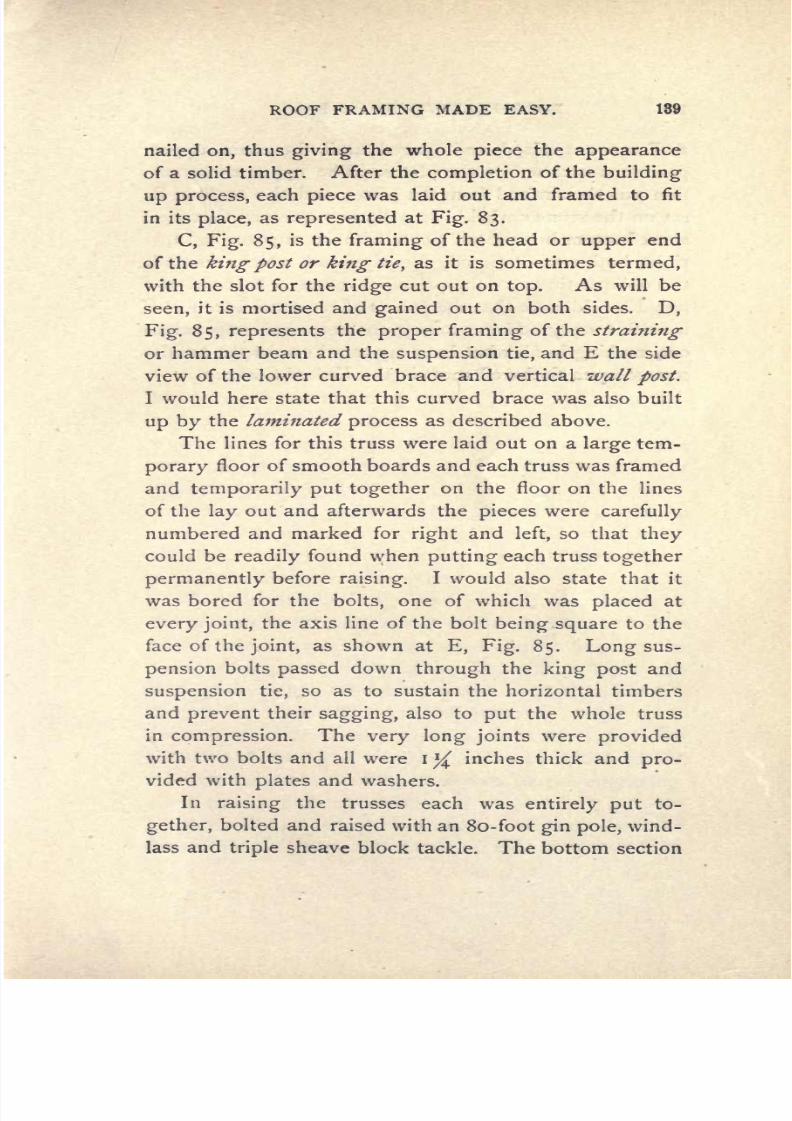
7/25/2019 Roof Framing Made Easy 1903
http://slidepdf.com/reader/full/roof-framing-made-easy-1903 141/174
ROOF
FRAMING
MADE
EASY.
139
nailed
on,
thus
giving
the
whole
piece
the
appearance
of
a solid
timber.
After the
completion
of
the
building
up
process,
each
piece
was
laid out
and framed to
fit
in
its
place,
as
represented
at
Fig.
83.
C,
Fig.
85,
is
the
framing
of
the head
or
upper
end
of
the
king
post
or
king
tie,
as it
is
sometimes
termed,
with
the
slot
for
the
ridge
cut out
on
top.
As will
be
seen,
it is mortised
and
gained
out
on both sides.
D,
Fig.
85,
represents
the
proper
framing
of
the
straining
or
hammer beam
and the
suspension
tie,
and
E
the side
view of
the
lower curved brace
and
vertical
wall
post.
I
would
here state that this
curved brace
was
also
built
up
by
the
laminated
process
as described
above.
The lines
for
this
truss were
laid
out on a
large
tem-
porary
floor of
smooth
boards
and
each
truss
was
framed
and
temporarily put
together
on
the
floor
on
the
lines
of
the
lay
out
and
afterwards the
pieces
were
carefully
numbered
and marked for
right
and
left,
so
that
they
could
be
readily
found when
putting
each
truss
together
permanently
before
raising.
I
would
also state
that
it
was bored
for
the
bolts,
one
of
which
was
placed
at
every
joint,
the
axis line
of
the bolt
being
square
to
the
face
of
the
joint,
as
shown
at
E,
Fig.
85.
Long
sus-
pension
bolts
passed
down
through
the
king
post
and
suspension
tie,
so
as to sustain
the
horizontal
timbers
and
prevent
their
sagging,
also
to
put
the whole
truss
in
compression.
The
very
long joints
were
provided
with two bolts and
all
were I
%
inches
thick
and
pro-
vided
with
plates
and
washers.
In
raising
the
trusses
each
was
entirely
put
to-
gether,
bolted
and
raised
with
an
8o-foot
gin
pole,
wind-
lass
and
triple
sheave
block
tackle.
The
bottom section
7/25/2019 Roof Framing Made Easy 1903
http://slidepdf.com/reader/full/roof-framing-made-easy-1903 142/174
140
ROOF
FRAMING MADE
EASY.
as
E
was not
raised and
placed
until
the
main
upper
portion
was
raised
on
the
plates.
The
upper
construc-
tion
was
then
raised
from
the
plates
and
the
section
E
set
on
the
stone corbel. It will
thus
be seen
that the
short
bottom
horizontal
beam
with
its
supporting
up-
right,
both
rested
directly
on
the
wall which
resisted
the
oblique
thrust
of
the
principal
rafters.
In
conclud-
ing,
1
would
state
that the
panels
of
the
truss were
filled
in
with
tracery
and
the
ceiling
above
the
rafters
paneled
out,
making
in all
what is
to
my
mind
one
of
the
hand-
somest
open
timbered
roofs
in
the
United States.

7/25/2019 Roof Framing Made Easy 1903
http://slidepdf.com/reader/full/roof-framing-made-easy-1903 143/174
ROOF
FRAMING
MADE
EASY.
HI
CHAPTER
XXX.
Bow
Truss
Roofs.
In the
construction
of
timber
roofs to cover
large
areas
where
an
open,
clear
space
underneath
is
of the
most
importance,
I
have been
much
impressed
lately
with the fact that
a
bow
or
curved form
of
truss
with
a
lattice
or
diagonal bracing
is
the
lightest
and
most eco-
nomical.
For this
reason
I have
deemed
this
subject
worthy
of a
chapter
and now
place
before
readers
some
practical
information
relative to
bow
trusses
and
their
construction.
These
trusses,
as
far
as I find from
inquiry,
can
be
very
cheaply
and
rapidly
put
together
and when
prop-
erly
built
are
capable
of
carrying
a
great
strain
and
give
a
clear unobstructed
area
under
them.
To
illustrate
the
foregoing
I
will
refer
the
reader to
the
illustration,
Fig.
86,
which
is the
elevation
of
one
of
twelve
bow
or
curved
or laminated
trusses
forming
the
roof
of
a
riding
academy
in
the
City
of New
York,
and
is,
I
believe,
one
of
the most recent
and
original
of
this
form in
the
East.
The
walls of
the
arena of
the
acad-
emy,
in
the
clear
of
the
span
measure
108
feet,
and
each
truss
has
a
bearing
of
2
feet
on
each
wall,
which
makes
its entire
length
112
feet,
as shown
in
the
engraving.
Each
truss
is
built
up
as follows
:
A
mold
for
bending
the
bottom
curved
planks
of
the
lower
chord
A,
Fig.
86,
about
25
feet
long,
was con-

7/25/2019 Roof Framing Made Easy 1903
http://slidepdf.com/reader/full/roof-framing-made-easy-1903 144/174
142
ROOF
FRAMING MADE
EASY.
structed
of
stout
plank
brackets,
spiked
to the floor
in
the
way
which
I
represented
in
a
previous
chapter
and
on
these
brackets
each
piece
was
bent
and curved
to the
radius
represented,
namely
105
feet.
On the back of
the
first
sprung
thickness or
piece
a
second
thickness
was
bent
and
nailed,
each
thickness
breaking
joint
to
half
the
length
of
the
piece
under,
so
as
to
give
the
pieces
strength
and
rigidity
as a
whole
piece,
this
method
54
Wrought
Iron
Plate
/
4 x8
i
Turlins
Fig.
86.
being
followed
till
the
entire
depth
of
the lower
chord,
namely
about
8
inches,
is
completed,
the
bending
boards
being
8
inches
wide
and
l/%
of
an
inch
thick,
taking nine
boards
to
make
up
the
depth.
When
completed
the
curvature
of
the
upper
chord
was
formed to
a
radius of
1
17
feet
and
the
upper
chord
built
up
in
the
same manner.
When
this was done the
two
chords
or
more
prop-
erly
laminated
wooden arcs
were
placed
on
the floor
in
the
position
shown
at
Fig.
86,
and
8x8
inch
diag-
onal
braces
of
yellow
pine
were
fitted
in
between the
soffit
of
the
upper
chord
and
the
extrados
of
the
lower

7/25/2019 Roof Framing Made Easy 1903
http://slidepdf.com/reader/full/roof-framing-made-easy-1903 145/174
ROOF
FRAMING
MADE
EASY.
143
as
seen,
the
soffit
of the
upper
chord
being
first
divided
into fourteen
equal parts,
and radial
lines
drawn
to
the
center,
marked
on
the
edge
of
the
lower chord
to
de-
termine
the
exact
thrust
points,
of
the
braces,
which
the
practical
mechanic
will
see
is
absolutely
necessary.
I
would here
state
that
this
system
of
laminating,
or
building
up
in
plates
or thicknesses
is
very
old,
so
that
there is
really
nothing
original
in the
foregoing
except
that
the
work
was done
on the floor
and
then
raised,
as
a
whole
completed
truss,
but the method of
sustaining
the
entire truss
in
its
arched
form
by
the
insertion
of
the
tension
rod,
without
having
recourse
to
any
outside
buttressing
of
the
wall
is,
as
far
as
I
know,
original.
This
i
y
tension
rod
of
wrought
iron
with
sleeves,
pins,
plates,
and
turnbuckles
is the
whole
sustaining
power
of
the
truss.
It is
made
up
of six
pieces,
the
two
on
each
end
passing
through
the center
of
two
10
feet
long,
^
inch
wrought plates
which stand
vertically
and
receive
the
full
thrust
of
both
the
upper
and
lower
chords.
It
will
be
noticed that
only
three
thicknesses
of
laminated
boards are
shown
on
this
engraving,
but
it
is
made
to
a
very
small
scale as
my
desire is
to show
the
principle
and
method
in
as
small a
space
as
possible.
When
the
braces were
fitted
in
and
properly
abutted
end
to
end,
the
entire
truss
was bound
and
tightened
with
I
inch
wrought
iron
tie bolts
with
washers and
nuts,
and
finally
the
tension
tie
put
in,
the
chords
being
bored
to receive
it.
When
together,
each
truss
was
raised with
a
gin
pole,
horse and
tackle.
Figs.
87
and
88
represent
two
different details
of
a
roof
for
a
building
designed
for
a
public
market,
and
as
readers
will
observe
it is also
a
laminated truss
roof,
but

7/25/2019 Roof Framing Made Easy 1903
http://slidepdf.com/reader/full/roof-framing-made-easy-1903 146/174
144
ROOF
FRAMING
MADE
EASY.
%
Wrought
Iron
Bolts
Fig.
87.
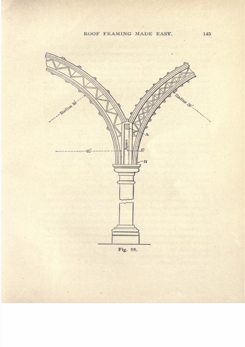
7/25/2019 Roof Framing Made Easy 1903
http://slidepdf.com/reader/full/roof-framing-made-easy-1903 147/174
ROOF FRAMING
MADE
EASY.
145
Fig.
88.

7/25/2019 Roof Framing Made Easy 1903
http://slidepdf.com/reader/full/roof-framing-made-easy-1903 148/174
146
ROOF
FRAMING
MADE
EASY.
instead
of
being
of a
segmental
form
it is
semi-circular,
thus
avoiding
the
use
of
the tension
rod
shown in
Fig.
86.
These
trusses
were made
up
of
three
I
J^
inch
thick-
nesses of
laminated
timber in
each
chord. The
span
be-
tween
the
columns
and
walls
measures 60
feet,
and each
truss
is
extremely
light,
being
with
the
columns
and
buttresses
spaced
10
feet
on
centres
longitudinally,
with
3x8
inch
purlins,
3x6
inch
braces
and
^
inch
wrought
iron bolts.
Particular
attention
is called
to
the
unusual
form
of
intermediate line
of
cast iron
columns
B
used
in
this
building
on which
the
chords
of
the
trusses
from both
sides
rest
in
perfect
equilibrium,
each
column
being
braced
longitudinally by
diagonal
braces
C
which are
framed
into the 6x8 inch
plate
A,
and
rest
on
the
im-
post
of
the
column
B.
I
sincerely
regret
that it
is
not
possible
for
me
to
give
larger
details
of
this
interesting
timber
structure,
as
it
is
an excellent
model to
copy
or
to
design
from
by
modifying
some
of
its
details to
suit
any
one
require-
ment,
especially
as
I
have
introduced
between the
chords
of
Figs.
87
and
88
several
methods
of
bracing
which
vary
in
strength,
the
intersecting
diagonal bracing
on
the
right
side
of
Fig.
88
being
of
greater strength
than
that
on
the
left
side,
and
the
spacing
here
being
different
from that
in
Fig.
87,
and
so
on as
the
designer
requires.
In
closing
let
me
warn
carpenters
who
may
lay
out
a
roof
truss not
to
skimp
material too
much,
but
make
sure the
truss
will
carry
its
load
safely
under
all
conditions.

7/25/2019 Roof Framing Made Easy 1903
http://slidepdf.com/reader/full/roof-framing-made-easy-1903 149/174
ROOF
FRAMING MADE
EASY.
117
CHAPTER
XXXI.
Roofs
for
Studios.
Fig.
89
gives
a
side
elevation
of
one
of the
com-
pleted
trusses,
showing
its
main
details.
B, Fig.
89,
is
a
lower
chord
or tie
beam
running
across
the
house
from wall to
wall,
being supported
at
M
and
N
by
heavy
12
x
12
inch columns
of wood.
C
is
an
upper
chord
in
compression
of
the
same
size
as
B,
which
is
in
tension.
D
is
the
sloping
rafter
on
the
north
side
of
very steep
Fig.
89.
pitch
to
receive
the
full
effect of
the
northern
light
which
is essential
in
order
to obtain the
very
best
work-
ing light
underneath.
As
every
carpenter
knows
the
value
of
the
northern
light
in
filing
saws
and so
forth,
I
need
not
go
into
lengthy explanation
as
to
why
this
side
of
the
roof
is
so
high
and
the
pitch
so
steep.
E
is
the
principal
rafter
on
the
south
side
of
the
roof
set
at
an
angle
of
about
45
in
order
to
gain
the full
benefit
of
the
southern
light
in
bringing
out
artistic effects in

7/25/2019 Roof Framing Made Easy 1903
http://slidepdf.com/reader/full/roof-framing-made-easy-1903 150/174
143
ROOF
FRAMING
MADE
EASY.
paintings,
statuary,
etc.,
and
here
I would
state
that
photograph
galleries,
usually
on the
top
stories
of
build-
ings,
have the
roof
constructed
of this
form
so
as to
ob-
tain
the
best
lights
and
shadows
on
the man
or
woman
beneath
when
having
his
or
her
picture
taken,
for
the
true
photographer,
if
he be
an
artist,
always
strives
for
the
most
artistic
effects
of
light
and
shade,
especially
on
the
features.
From
this
short
explanation
any
one
can
see
why
roofs for
lighting
are
thus
constructed.
Referring
again
to
Fig.
89
it will
be
noticed
that
a
special
form
of
bracing
is
introduced,
to
properly
sup-
port
the
great
weight
of
glass
in
the
roof,
and
to
stiffen
it
sufficiently
to
resist
wind
pressure.
H,
H
;
I,
I,
and
P,
P,
being
mortised
and tenoned
tightly
in
at
the
angles
to
carry
the
strain
all
down
to
the
posts and
col-
umns.
The
joints
marked
A
were
halved
together
and
those
at
M,
N
and
R,
R
were
dowelled as
was
the
abut-
ting joint
S.
Q
and
Q
are
the
two
longitudinal
wall
plates,
which
carry
the
rafters
T
and
U
;
the
deck
or
top
rafter
V,
resting
on
and
nailed
to
the
longitudinal
purlins
J.
On
account
of
the
great
height
of
this
roof,
the
Narth
principal
rafters
D
being
20
feet
long,
it
will
be
seen
that
there
was
ample
room
for
studios in
its
interior,
the
trusses
being
spaced
15
feet
apart.
The
span
over
all,
from outside
to
outside
of
walls,
measure
50
feet;
lower
chord,
12
x
14:
principal
rafters,
12
x 12
;
braces,
lox
12;
plates,
6x8;
purlins,
8
x
14,
so
that
it
will be
seen
that it
is
an unusual
roof.
The
rafters
were
arranged
for
receiving
the
glass
with
a
groove
to
carry
off
all
condensed
water
or
possible
leakage
from
rain.

7/25/2019 Roof Framing Made Easy 1903
http://slidepdf.com/reader/full/roof-framing-made-easy-1903 151/174
ROOF
FRAMING
MADE
EASY.
149
CHAPTER
XXXII.
How
to
Build a Circular Framed Tower
with
a
Molded
Roof.
Circular
towers
in framed
construction
may
be
di-
vided
into
two
classes
namely,
those
which
have
their
foundations
on a line
connected
with
the main founda-
tion
of
the
house,
and
second,
those
which are
carried
up
from
the
second
floor,
resting
on,
or
being
supported
by,
the
floor beams
of
the
second
story.
The
latter
class
will be
considered,
as
it embodies more
important
construction,
although
some
of
the matters
which
will
be
treated
are
applicable
to
all
circular towers.
The
first
thing
for the
practical
carpenter
or
builder
to
consider
is
how
to
so construct
the
floor
as
to
support
the
tower
in
a
proper
manner
;
that
is,
so
that
it
will
sustain
with
perfect
safety
the
weight
to be
placed
upon
it.
Referring
to
the
accompanying
illustrations,
suppose
Fig.
90
to
represent the
general
appearance
of a
tower
built on
an
angle
of
a
house. It is
placed
at the
left
hand
of
the
front
of
the
building
and
is
designed
to
form
an
alcove
closet,
or
an
extension
to
the
corner
room.
Its
plan,
as
may
be seen from
an
inspection
of
Fig.
92
of
the
engravings,
is
a
three-quarter
circle,
the
apex
of
the
angle
at
the
corner
being
the center from
which
the
circular
plan
is
struck.
The
radius
of
the
plate
outside
is
3
feet
9
inches,
thus
making
the tower
7
feet 6
inches
in
diameter.
It
is
intended
that the
tower
floor
shall
be
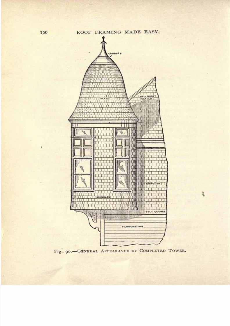
7/25/2019 Roof Framing Made Easy 1903
http://slidepdf.com/reader/full/roof-framing-made-easy-1903 152/174
150
ROOF
FRAMING
MADE
EASY.
7IHHI I I
I
I
SLATE
\\
\
r,'
1
r\\'1
\V^TTJjt.AT
l
ED
/////]
I
IN
i
I
ml
1
, iV^vil I
I
i.Miiiilf
'I 'i
:
-'
9
o.
GENERAL
APPEARANCE
OF
COMPLETED
TOWER.

7/25/2019 Roof Framing Made Easy 1903
http://slidepdf.com/reader/full/roof-framing-made-easy-1903 153/174
ROOF
FRAMING
MADE
EASY.
lol
level
with
a room
in
the
second
story,
and
the beams
or
joists
must be
framed
in such
a
manner
that
the
floor-
ing
can
be laid
in
the
circle
of
the
tower,
while
at
the
same
time
being
so secured
as
to
support
the
weight
of
it.
The
form
of
construction
indicated
in
Fig.
92
is
well
adapted
for
the
purpose,
and
an
inspection
will
show
that
it
consists
of a
double
header made
of
2
x
10
inch
timbers
placed
diagonally
across
the
corner
at
a suffi-
cient
distance
back
from
it
to
give
ample
leverage
to
counterbalance
the
weight
suspended
outside
the
plate.
Fig.
92.
The
tower
beams are framed
square
into
this
header
on
the
outside
and
the
floor
beams
are framed into
it
on
the
inside.
By
this construction
a
cantilever
is
formed,
for
the
header
in
carrying
the
main
beams
forms
a
counterpoise
for
the
superadded
weight
which
is
borne
by
the
unsupported
beams which
project
outside.
It
will
be
readily
seen
that this
is a
good
construction,
and
much
better
than
introducing
many
short
timbers
after
the
manner
indicated
in
Fig.
93
of
the
engravings.
In

7/25/2019 Roof Framing Made Easy 1903
http://slidepdf.com/reader/full/roof-framing-made-easy-1903 154/174
152
ROOF
FRAMING
MADE
EASY.
the
latter case
the
leverage
outside
being
much
greater
than
that
inside,
the
plate
being
the
fulcrum,
there
is
a
strong
probability
of
its
tearing
away
from
the
main
Fig. 91.
ELEVATION OF
TOWER
FRAMING.
framing.
For
the
same
reason it
is
regarded
as
a
seri-
ous mistake to
attempt
to
radiate
the
timbers
as indi-

7/25/2019 Roof Framing Made Easy 1903
http://slidepdf.com/reader/full/roof-framing-made-easy-1903 155/174
ROOF FRAMING
MADE
EASY.
153
cated
by
the
dotted
lines
in
Fig.
93.
The
position
of
the
timbers
are
better
shown
in
the
elevation
of
the
framing, Fig.
91,
and
we
have
no
doubt
that
practical
carpenters
will
fully
appreciate
what
has been
pointed
out.
When the beams
are
inserted
and
the
main
framing
has been
nailed,
a bottom
circular
plate,
or
template,
marked
A,
in
Fig.
91,
is made from
two
thicknesses
of
I -inch
stuff,
and nailed
on
exactly
the
size
required.
The
position
of
the
window
studs
is
also
marked
on
it,
Fig
93-
as
represented
in
Fig.
92.
The
upper
plate,
or
which
is
really
the
wall
plate
proper,
and
indicated
by
B
in
Fig.
91,
must
also be
made,
and this will
rest on the
top
ends
of
the
studding
and
support
the
rafters.
This
plate
will
i>e
a
complete
circle
measuring
7
feet 6 inches
in
diam-
eter
and
struck with a
3
foot
9
inch
radius
rod
and
laid
out
upon
the
floor,
as
indicated
in
the roof
framing
plan,
Fig.
94.
The
pieces
necessary
to
form
the
upper
and
lower
plates
may
be
sawn
out
of
rough
i-inch
pine
boards
from
one
pattern,
which
may
be
any
one of
those
drawn
in
the
plan,
and a
number
of
which
go
to
make
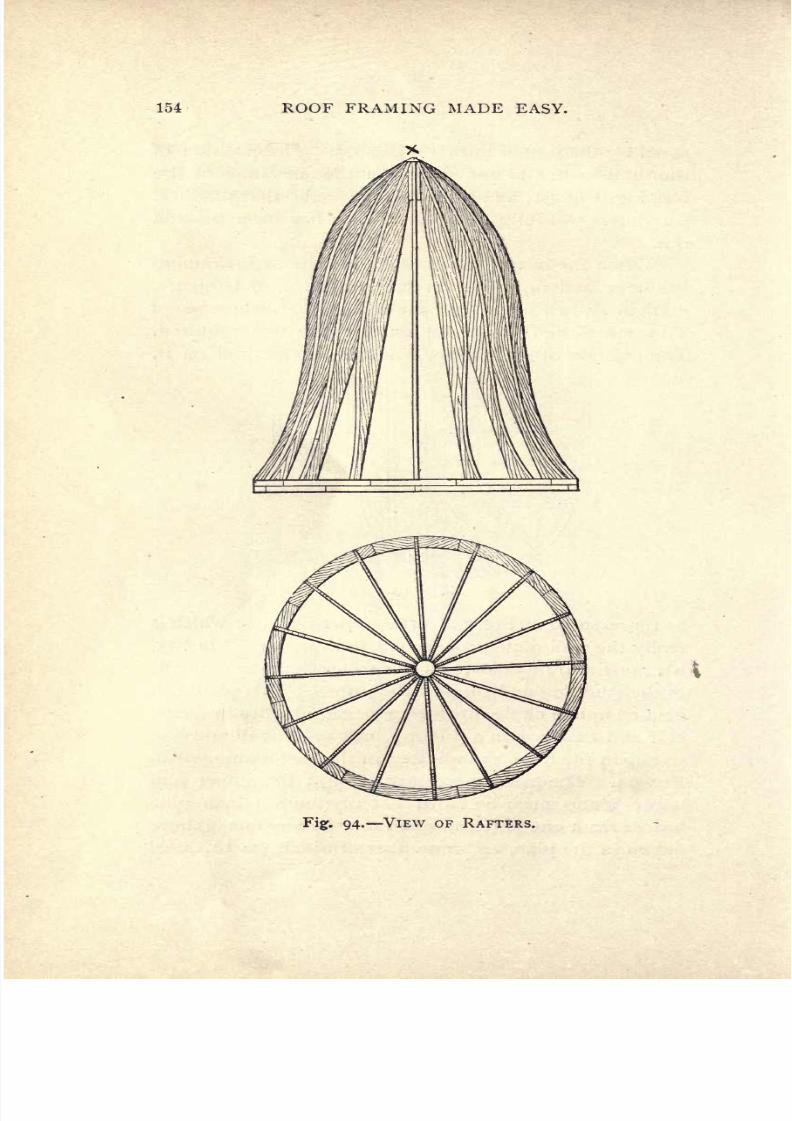
7/25/2019 Roof Framing Made Easy 1903
http://slidepdf.com/reader/full/roof-framing-made-easy-1903 156/174
154
ROOF
FRAMING
MADE
EASY.
Fig.
94.
VIEW
OF
RAFTERS.

7/25/2019 Roof Framing Made Easy 1903
http://slidepdf.com/reader/full/roof-framing-made-easy-1903 157/174
ROOF
FRAMING
MADE
EASY.
155
up
the
whole
plate.
The
studding
are
cut
1 1 feet
8
inches,
which
being
added
to
4
inches,
the thickness
of
the
plates,
makes
the
entire
height
12
feet.
The
win-
dow
headers,
both
at
the
top
and
bottom,
are
likewise
circular
and
are
framed
in
after
the
manner
represented
in
Fig.
91,
to
form the
openings
and
cripple
or
short
studding
cut
in
under
them
in
the
center.
All
studding
must
be
set
perfectly
plumb
and
all
plates
and
headers
perfectly
level.
In order
to insure this
it
is
well to
be
certain
that
the
bottom
plate
is
level
by placing
a
par-
allel
straight edge
with
a
spirit
level
on
top
of
it,
across
the
plate
at
different
points.
Then,
if the
studding
be
cut
of
equal
length
the
upper
plate
must,
in conse-
quence,
be
placed
in a
level
position.
A
number
of
horizontal
sweeps,
2
inches
thick
and
4
inches
wide,
as
indicated
at
C
in
Fig.
91.
require
to
be
cut
out
to
form
ribbing
or
pieces
nailed
in
16
inches
apart,
to
which the
vertical
boarding
outside
and the lath
and
plaster
inside
are
fastened.
It
will
be
seen
that
if
this
construction
is
followed
the
whole
cylindrical
wall
can
be
very
strongly
and
economically
built
up.
To
save time
and
labor
and
also
to
expedite
matters,
the
sweeps
may
be
sawed out
at
the
mill
with
a
band
saw,
although
it
can
be
done
in
pine
on
the
job
with
the
compass
saw.
With
regard
to
the
molded
roof,
it
may
be said that
having
a
molded
outline it
will
necessarily
require
molded
rafters
sawn
to
the
curvature
called
for in
the
elevation.
As
a
general
thing,
architects
furnish
a
full
size
working
detail
for
roofs
of
this
kind,
but
it
often
happens
that
it
is
not
forthcoming
and
the
carpenter
or
builder is
obliged
to strike
out
a
pattern
rafter himself.
To
do
this
quickly
and as
accurately
as
possible,
it
is
7/25/2019 Roof Framing Made Easy 1903
http://slidepdf.com/reader/full/roof-framing-made-easy-1903 158/174
156 ROOF
FRAMING
MADE
EASY.
well
to
lay
out the
whole
roof
on a
floor,
something
after the
following
manner :
Referring
to
Fig.
95,
draw
any
base
line
7
ieet 6
inches
in
length,
as
A
B,
and di-
vide
exactly
in
the
center,
or at
3
feet
9
inches,
as
C.
From
C
square
up
the
line
to
9
feet
high,
as
C
D,
and
divide this
line into
13
equal
divisions,
as
I,
2,
3,
4,
5,
6,
&c.
Through
these
points
draw
lines
parallel
to
A
B,
or
square
C
D
any length
on each
side
of
C
D.
Now,
from the
point
D
draw the
curve
of
the
rafter,
as
indi-
cated
by
the
letters
E, F, G, H,
I,
J,
K,
L, M,
N,
O
and
P,
as
near to the outline
as
possible.
A
very
good
method
of
obtaining
these curves is
to
divide
the
archi-
tect's
i^-inch
scale
drawing by
horizontal
division
lines
similar
to those
in
Fig.
95
and
to
scale off
the
lengths
from
the
axis
or vertical
line
C
D.
By
setting
off
these
measurements
on
a
full size
lay
out,
points
will
be
ob-
tained
through
which the
flexure
of
the
curves
may
be
very
accurately
determined.
The
1
6
rafters
may
all
be
drawn
from
the
one
pat-
tern,
as
they
are
all
alike
and
should
be
framed
to
fit
against
a
3
inch
wood
boss
as indicated
by
X
in
Fig.
94.
In
this
engraving
the
rafters
are
shown
in
position
in
elevation
and
also
in
plan,
as
well as
the
way
they
radi-
ate
or
are
spaced
around
the
circle
16
inches
apart
o4
the
plate.
As
it
is
always
best to
board
such
roofs
as
this
vertically,
ribbing
or
horizontal
sweeps
will
have
to
be
cut
in
between
the
rafters,
and
as
there
should
be
as
many
of
these
as
possible
for
the
purpose
of
giving
a
strong
framework
to
hold the
covering
boards,
it
is
ad-
visable
to
cut
in
one
at
each
of
the
divisions
marked
on
the elevation
shown
in
Fig.
95.
The
outline
plan
of
this
figure
represents
the
top
lines
of
these
sweeps,

7/25/2019 Roof Framing Made Easy 1903
http://slidepdf.com/reader/full/roof-framing-made-easy-1903 159/174

7/25/2019 Roof Framing Made Easy 1903
http://slidepdf.com/reader/full/roof-framing-made-easy-1903 160/174
158
ROOF
FRAMING
MADE
EASY
which
are
well nailed
in
between
the
rafters.
Fig.
96
shows
the
exact
size
of
the
headers
and
their
positions
when
nailed
in.
They
are struck
from
different
radii,
which
shorten
as
they
go upward.
It
will
be
noticed
that
each
set of
sweeps
is
consecutively
numbered
with
the
lines
C,
i,
2,
3,
etc.,
from
C
to
D
of
Fig.
95.
There
Fig.
96.
will be
13
sweeps
in
each
course
and,
therefore,
15
dif-
ferent
patterns.
They
may
be
conveniently
numbered
and marked
in
the
following
manner
:
For
No.
2,
fo?
example,
a
pattern
can
be cut
and
marked
Pattern for
15
sweeps,
No.
2.
There
will,
therefore,
be 180
alto-
gether
to
be
cut
out,
and these
should
be
cut
a
trifle
longer
than
the exact
size,
in
order
to
allow for
fitting.

7/25/2019 Roof Framing Made Easy 1903
http://slidepdf.com/reader/full/roof-framing-made-easy-1903 161/174
ROOF FRAMING
MADE EASY.
159
CHAPTER
XXXIII.
Details
and
Suggestions.
All the timber used
in
roof
trusses,
should
have
been
felled
at
least
two
years
and should
have
been
at
least
six
months out
of water.
Modern
builders,
but
too
often
employ
timber
soaked
with
water,
and
the
result
after
a
few
months
is
considerable
shrinkage
and
consequent
splitting
from
abutting
joints.
This
very
often
happens
with
struts
and
principal
rafters,
the first
at
the
head
and
the
second
at the
feet.
A
good
preventitive
against
this
evil
may
be
made,
by leaving
the
abutting
joints
open
at the
internal
angle
nearest
the
post.
All
spikes
used
in
building
construction
should be
flat-edged
and not
twisted
as
some
are,
and
they
should
be driven
with
the
edge
across the fibre
of
the
wood
and
not
longitudinally
with
the
timber
which
would
tend to
split
it.
With
regard
to
bolts,
when
they
are
round,
the
hole
made
to receive them
should
be
exactly
of the
same di-
ameter as
that
of the
bolt,
and
it
should
be driven
ex-
actly parallel
to the sides
of
the
wood that
are
to be
parallel
to
the
bolt.
For
square
bolts
the
bolt-hole
should
be
somewhat less
than
the
diagonal
of
the
bolt.
Bolts and nuts should be well
greased
or
dipped
in
oil
before
they
are
used.
Bolts
of
great
length
should
be of
sufficient diameter to
resist
torsion,
and
they
should never be
placed
too
near
the
end
of
a
timber.

7/25/2019 Roof Framing Made Easy 1903
http://slidepdf.com/reader/full/roof-framing-made-easy-1903 162/174
160
ROOF
FRAMING
MADE
EASY.
Care
should
be
taken
that
screw
bolts
and
screws
be
never
hammered,
as the fibres
of
the
wood
are
thereby
torn.
It is a
great
error
to
fancy
that the
elasticity
of
the
wood
will
prevent
this
laceration.
Whenever
it
is
feared that a
nut
may
slacken
by
a
retrograde
motion,
a
check
nut
may
be
added,
which
will
effectually
prevent
any loosening.
Iron
straps
and
stirrups
should
always, before
use,
be
heated
to a
blue
heat and
then struck over
with
raw
linseed
oil
as
a
preventitive
of
rust.
Our
modern
rolled
and
stamped straps
and
stirrup
irons,
have obviated
the
use
of
the
foregoing,
but
the
writer
is
glad
to
see that
some
of
the
older
and more
experienced
architects
insist
on
its
being
done
even on
the rolled
straps.
A
strap
i
inch
wide
may
be
3-16
thick,
\y
inch
wide
may
be
5-16
thick
and
2
inches
wide,
^
thick.
Straps
should be
secured
by lag
bolts,
and
if
the
timber
be
not
too
thick,
the bolts should
pass through
it
and
have
good
large
washers.
Cast
iron
plates
and
shoes
are
very
useful to
receive
and
to
equalize
the
thrust from the
ends
of
butting
timbers,
the first
partic-
ularly
where
they
are
employed
as a
connecting
surface
between the
butting
ends
of
timbers,
which from
shrink-
age,
defect
of
workmanship,
or otherwise
may
come
to%
bear
upon
opposite
angles,
instead
of
the
whole
area of
their intended
connecting
surfaces.
It
is a
very dangerous practice
to
hammer
rolled or
wrought
iron
straps
when
cold,
they
may get
an
invisi-
ble
fracture.
The duties
of
king-posts
and
queen-posts
are
now
efficiently
performed
by
wrought-iron suspension
rods
and
they
may
be of
from I inch
to
2
inches
in
diam-
7/25/2019 Roof Framing Made Easy 1903
http://slidepdf.com/reader/full/roof-framing-made-easy-1903 163/174
ROOF
FRAMING
MADE
EASY.
161
eter.
They
will
pass
through
timbers and
be
secured
by
nuts,
outwardly
of
three
times
the
diameter
of
the
bolt,
when
in
connection
with
struts
they
may
pass
through
the
cast-iron
shoe
receiving
the
strut.
We
may
by
these
means
suspend
the tie
beam
from
any
number
of
points
and construct
a
truss
of
great
span
with
little
weight.
It
must
be
remembered
that it
is
always
wise
to
give
careful
consideration
to
bearing
joints
so
as
to
ensure
the
stability
of the
structure.
The
methods
of
joining
timbers
are
various
and
they
should be
always
con-
structed
according
to the
position
and
strain
on
the
con-
nected
timbers at
the
joints;
tenon
and
mortise,
joggle,
notching,
butting joints,
scarfing
and
building,
or
modi-
fications
of
these
are
the
principal
combinations of
tim-
bers
in
trusses.
In
tenon
and
mortise,
the
tenon
is
cut
on
the
end of
one timber
and
the
mortise
is
cut
in
the
face
of another
to
receive
the
tenon.
In
the
square
tenon and
mortise,
the
thickness
of
a
tenon
is
made
one-third of
that of the
timber
in
which
it
is
cut
;
the shoulders
should
be
in
ex-
actly
one
plane
and
perfectly perpendicular
to the axis
of
the
timber
on which
the
tenon
is
cut
;
by
these
means
after
shrinkage
there
will be
obtained
an
equal
bearing
which is
most
desirable
in case of
weight
on the shoul-
ders
one
of
which
would
otherwise
have
a
tendency
to
split
from
the
main
timber
;
the
size
or
sectional
area of
the
mortise
must be
quite
parallel
to
the
axis of
the
tim-
ber
in
which
it
is
cut
;
when
acting
by
suspension
but
little
depth
is
required
if
secured
by
a
strap.
An
oak
pin
or
bolt
should be driven
through
mortise
and
tenon,
the
whole
being
bored
after the
joint
is
adjusted
and
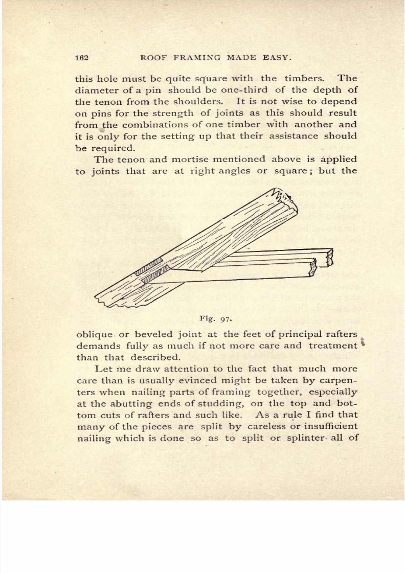
7/25/2019 Roof Framing Made Easy 1903
http://slidepdf.com/reader/full/roof-framing-made-easy-1903 164/174
162
ROOF
FRAMING
MADE
EASY.
this
hole
must
be
quite
square with
the
timbers.
The
diameter
of
a
pin
should
be
one-third
of the
depth
of
the tenon
from the
shoulders.
It
is
not
wise
to
depend
on
pins
for
the
strength
of
joints
as
this
should result
from the
combinations
of
one
timber
with
another
and
it is
only
for
the
setting
up
that their
assistance
should
be
required.
The
tenon
and
mortise
mentioned
above
is
applied
to
joints
that
are
at
right
angles
or
square
;
but the
Fig. 97.
oblique
or beveled
joint
at the feet
of
principal
rafters
demands
fully
as
much
if
not
more
care
and
treatment
than that
described.
Let
me draw
attention
to the
fact
that
much more
care than
is
usually
evinced
might
be
taken
by carpen-
ters
when
nailing
parts
of
framing together,
especially
at
the
abutting
ends
of
studding,
on
the
top
and
bot-
tom
cuts
of rafters
and
such like.
As a rule
I
find
that
many
of the
pieces
are
split
by
careless
or insufficient
nailing
which
is done
so
as
to
split
or
splinter-
all
of

7/25/2019 Roof Framing Made Easy 1903
http://slidepdf.com/reader/full/roof-framing-made-easy-1903 165/174
ROOF FRAMING
MADE
EASY.
163
the
stuff
and
lessen
its
holding
capacity.
This
could
be
easily
avoided
by entering
each nail
more
carefully.
Another
thing
is to be sure to
straighten
all
studding,
beams and
roofing
timbers
through
from
end to
end
so
they
will be
set
rigid
and
upright,
in
order
to
gain
their
utmost
strength.
If
any
timbers be
warped
they
should
be
straightened
up
or
bridged
in
some
way
so
they
will
not
twist
more.
The
foregoing
I
would
especially
ap-
ply
to
hemlock
and
spruce,
as
many
pieces
are
warped
and
need a
little
care.
Fig.
97
represents
a
joint
in
a
truss
roof on
a
school
house
at
Eighty-fifth
street
and
Madison
avenue,
in
the
City
of
New
York,
introduced for
the
purpose
of
pre-
venting
the
principal
rafters
from
buckling.
SHRINKAGE
OF
TIMBER
BY
SEASONING.
Southern
yellow
pine
from
i8f
to
18^
Spruce
8
J
8f
American
white
pine
12
1
ij
Cedar
14
13
Elm
n
iof
Oak
12
i
if
,
VERTICAL
PRESSURE
ON
ROOFS.
Roofs
covered
with
corrugated
iron
without
boards,
the
pressure
to
the
square
foot is. ...
8
Ibs.
Same,
and
plastered
below
rafters
18
Covered
with
slate
laid
on
I x 2
inch
lath
13
Same,
and
plastered
below
rafters
23
Covered
with
slate
on
i
J/
or
^3
-inch
boards.
.
.
16
Same,
plastered
below
rafters
26
Shingles
on
I
x
2 inch
lath.
.
10
Same,
plastered
below rafters
20
Shingles
on boards
13

7/25/2019 Roof Framing Made Easy 1903
http://slidepdf.com/reader/full/roof-framing-made-easy-1903 166/174
164
ROOF
FRAMING
MADE
EASY.
This
table
for
spans not
exceeding
75
feet.
From
75
to
150
feet,
add
4
pounds
to
each
number.
AVERAGE
WIND
PRESSURE.
Pitch
in
degrees.
Rise of
roof.
Pressure
in
Ibs.
5
i
5-2
10
2-J-
9.6
15
3i
14-0
20
4
f
18.3
25 5i
22.5
30
6&
26.5
35....
8f
30.1
40
10
33-4
45
12
36.1
50
i4ro
38.1
55
i7i 39-6
60
20f
40.0
The
above
table
is for
the
pitches
mostly
used
by
architects.
In conclusion
I
would recommend
mechanics
to
be
more
particular
and
spend
more time
on the
process
of
measuring,
and
note
down
any
peculiarities
that
may
exist
in
the construction
and make
sketches and remarks
about
same
especially
when
measuring
up
for new
work.
THE
END.

7/25/2019 Roof Framing Made Easy 1903
http://slidepdf.com/reader/full/roof-framing-made-easy-1903 167/174
How to
Measure
Up
Woodwork
FOR
BUILDINGS
BY-
OWEN B.
MAGINNIS.
Architect
Inspector
of
Buildings
of the
City
of
New York
Author
of
Roof
Framing
Made
Easy''
How
to
Build
a
House
Bricklaying
etc.,
etc.
Illustrated
by
160
Engravings.
12mo.,
Neatly
and
Durably
Bound
in
Cloth.
PRICE
50
CENTS
THIS
book was
written
so as
to
place
in
handy
and
concise
form
reliable
directions
to
enable builders
and
mechanics
to
measure
up
the
quantities
of
woodwork for
brick and
frame
houses
accurately
and
without
hesitation,
figuring
either from
plans
or on
the work.
By
its
aid
blunders in
ordering
stuff
can
be
avoided
and
much
valuable time
and
money
saved.
The
following synopsis
of
the
contents
will
show
the
wide
scope
of
the
book,
embracing
as
it
does
all
forms
of
woodwork:
Measuring
window
frames
and
sashes;
Door
jambs, base,
trim,
wainscoting;
Getting
sizes of
doors;
Finding
dimensions
of
house
fixtures;
Determining
sizes
and
quantities
of
portiere
screens,
transoms and
mouldings;
Measuring
up
stairs,
balusters
and
handrails;
Getting
sizes
for
inside
and
outside
shutters
and
blinds;
How
to
figure
up rough
timber for
frame
buildings;
together
with
miscellaneous
information,
tables,
etc.,
etc.
A
copy
of
this
book
will
be
sent postpaid
on
receipt of
price.
Address
INDUSTRIAL
PUBLICATION
CO.
16
Thomas
Street
^
*
NEW
YORK

7/25/2019 Roof Framing Made Easy 1903
http://slidepdf.com/reader/full/roof-framing-made-easy-1903 168/174
REISSMANN'S
R.AFTER
AND
POLYGON
GAUGE
will
give
the
correct
side
and mitre
cuts for
a
pentagon,
hexagon,
heptagon,
octagon, nonagon,
decagon,
undecagon
and
dodecagon.
The
length
of
common,
hip
valley
and
octagon hip
rafters.
The
pitch
plumb
and
side
cuts
for the above-named
rafters.
The
side
bevel
of
jack
rafters
against hip
and
valley
rafters,
and
also
the
side
bevel
of
jack
rafters
against
octagon
hip
rafters.
The
mitre
cuts
for
level
planceer,
gable
planceer,
crown
moulding,
sheathing
and
shingles
for
hip
and
valley.
The
degrees
from
1
to
90,
and
a scale
representing
1
inch
to
1
foot.
A
little
study
and
practice
of
this
eminent
and
useful
article
will
prove
itself
indispensable
to
every
mechanic
connected
with
the
building
industry.
This
gauge
has received the indorsement
of
many
practical
men
who
have
used
it and
found
it reliable
and
handy.
Every
wide-awake
carpenter
should
own
one,
and
the
price
is
so
low
that
it is
within
the reach
of
every
one.
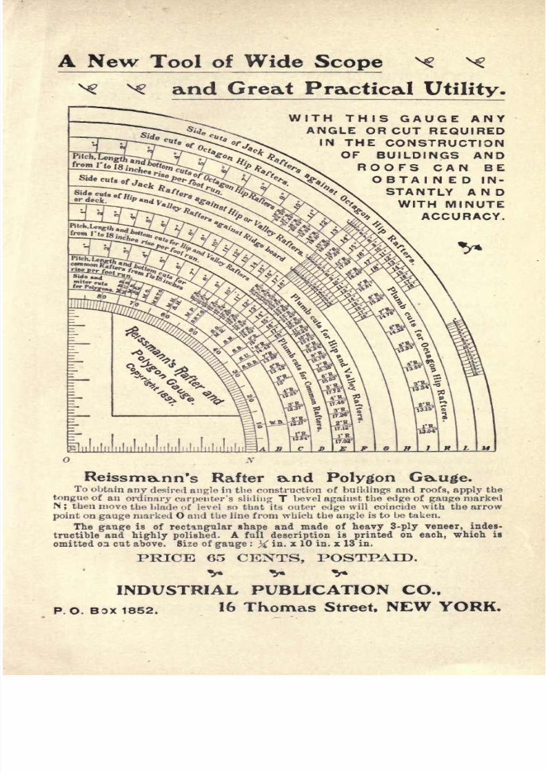
7/25/2019 Roof Framing Made Easy 1903
http://slidepdf.com/reader/full/roof-framing-made-easy-1903 169/174
A
New
Tool
of Wide
Scope
N?
x
^ ^
and
Great
Practical
Utility.
WITH
THIS
GAUGE
ANY
ANGLE
OR
CUT
REQUIRED
IN
THE
CONSTRUCTION
OF
BUILDINGS
AND
ROOFS
CAN
BE
OBTAIN
ED
IN-
STANTLY AND
WITH
MINUTE
ACCURACY.
01i. I.
.In iiliili.ln nl.il., ,,
nlnliili
ReissmaLnn's Rafter
a^nd
Polygon
G^uge.
To
obtain
any
desired
angle
in
the
construction
of
buildings
and
roofs,
apply
the
tongue
of
an
ordinary
carpenter's sliding
T
bevel
against
the
edge
of
gauge
marked
N
;
then
move
the
blade of
level so that
its
outer
edge
will
coincide
with
the
arrow
point
on
gauge
marked O
and the
line
from
which
the
angle
is
to
be
taken.
The
gauge
is
of
rectangular
shape
and
made
of
heavy 3-ply
veneer,
indes-
tructible
and
highly
polished.
A
full
description
is
printed
on
each,
which
is
omitted
on
cut
above.
Size
of
gauge
:
%
in.
x
10
in.
x
13
in.
PRICE
65
CE1STTS,
POSTPAID.
INDUSTRIAL
PUBLICATION
CO.,
P.O.
BOX 1852.
16
Thomas
Street,
NEW
YORK.

7/25/2019 Roof Framing Made Easy 1903
http://slidepdf.com/reader/full/roof-framing-made-easy-1903 170/174
EASY LESSORS
IN
MECHANICAL
DRAWING AND
MACHINE
DESIGN.
Arranged
for
Home
Study
Without a
Teacher.
By
J. G. A.
MEYER
and
CHARLES
G.
PEKER.
Published
in 20 Parts
at
. . . .
50c.
each,
Or the
whole,
handsomely
bound
in
cloth
$10.00
This is a
Thoroughly
Reliable Work
which furnishes the
Elements of
a
Mechanical
Education
in
Every
Department.
Among
other
subjects
closely
connected
with
Designing,
it
gives
:
Useful
Data for
Designing,
accompanied
by
first-class
Working
Drawings
of
Modern
Machine
Tools
;
Simple
and
Compound
Steam
Engines
and
many
other
illustrations
necessary
for
procuring
a
clear
conception
of
the
principles
governing
the
Reading
and
Making
of
Working
Drawings
of
Every
Description,
including
Development
of
Surfaces
Applied
to
Laying
Out
Boiler
and
Sheet
Iron
\Vork
;
Designs
of
Boilers;
Construction of
Gears,
etc.,
etc.
It
also
furnishes
full Instruction
in
Mensuration
;
Elementary
Mechanics
;
Graphic
Statics;
Strength
of Material.
All
the
subjects
are
presented
in a series
of
carefully
graduated,
progressive,
easy
and
comprehensive
lessons
;
the
whole
forming
a
Valuable
Boole
of
Instruction
as
well
as
a
Complete
Library
of
Reference
for
apprentices,
student?
in
Correspond-
ence
and
evening
schools,
marine
and
stationary
engineers
and
for all
engaged
in
the
manufacturing
industries,
whether
as
workmen,
sellers
or
users of
machinery
Full
descriptive
circular
and
specimen
pages
will
be
sent
to
any*
address
on
request.
The
Steel
Square
and
Its
Uses.
HODGSON. 100
Engravings.
Cloth
51.00
The
most
valuable
aid to mechanics
ever
published.
Practical
Carpentry.
HODGSON.
300
Engravings.
Cloth
Gl.OO
Unequaled
for
accuracy,
simplicity
and
practicality.
Stair
Building
Made
Easy.
HODGSON.
Fully
Illustrated. Cloth
$1.00
Simple,
plain
and
thorough.
May
be
learned
by any
good
mechanic.
The
Hardwood Finisher.
By
FRED
T. HODGSON.
Cloth
$1.00
A
thoroughly
reliable
guide.
The
Workshop
Companion.
A Collection
of Useful and Reliable
Recipes,
Rules,
Processes,
Methods,
Wrinkles and
Practical Hints
for
the
Household
and
the
Shop.
Paper
35c.
Century
of Inventions.
By
the
MARQUIS
OF
WORCESTER.
Edited
by
JOHN
PHIN.
A wonderful book. Cloth
$1.00
Hints
for
Beginners
with the
Microscope.
JOHN
PHIN.
Cloth
50c.
The
Marvels
of
Pond
Life.
SLACK.
Fine
Illustrations.
Cloth
$1.00
As
interesting
as
a
fairy
tale.
How
to Become a
Good
Mechanic.
PHIN.
Paper
i
25c.
Common
Sense
in
the
Poultry
Yard.
By
J. P.
HAIG.
Cloth
;
neat
$1.00
The
most
practical
book
on
the
subject
in
market.
The
Sun.
A
book
descriptive
of
our
great physical
source
of
Light,
Heat
and
Life.
THOMAS
W.
WEBB.
Cloth
25c.
The
Natural
History
of
Hell.
A
Discussion
of
the Relations
of
Christianity
to
Modern
Science.
Paper
25c.
A
Book
About
Books.
Practical Hints
on
the
Selection and
Care
of
Books,
and
on
Reading
for Pleasure and Profit.
Cloth
25c.
Shakespearean
Notes
and
New
Readings.
JOHN
PHIN.
Paper
25c.
J3^
Send
for
our
Large
Descriptive
Catalogue
(Free).
THE
INDUSTRIAL
PUBLICATION
COMPANY,
P.O. Box 1852.
16
THOMAS
STREET,
NEW
YORK.

7/25/2019 Roof Framing Made Easy 1903
http://slidepdf.com/reader/full/roof-framing-made-easy-1903 171/174

7/25/2019 Roof Framing Made Easy 1903
http://slidepdf.com/reader/full/roof-framing-made-easy-1903 172/174

7/25/2019 Roof Framing Made Easy 1903
http://slidepdf.com/reader/full/roof-framing-made-easy-1903 173/174

7/25/2019 Roof Framing Made Easy 1903
http://slidepdf.com/reader/full/roof-framing-made-easy-1903 174/174