Roof fans Product specific VD and VDR information
29
■ Design VDR.. Vertical discharge centrifugal roof fan with isolation switch on the casing. Casing and base plate made of galvanised steel. The fans are factory-wired with the isolation switch. The base plate of casing is sup- plied with drilled holes (hole pat- tern to DIN 24155, Bl. 3) in or- der to connect the supply air accessories. ■ Motor The units are operated by totally enclosed external rotor motors (IP 44), in the air stream. Their design complies with DIN EN 60034 / VDE 0530 and DIN EN 60335-1 / VDE 0700-1, of the insulation class B and protection class I. They are equipped with maintenance free ball bearings, which are suitable for up to 30.000 operating hours. ■ Impellers Highly efficient, backward curved centrifugal impellers made of polymer. Low vibration operation through dynamic balancing according to DIN ISO 1940 T.1 – grade 6.3. ■ Air flow temperature The units can be used in the range of – 40 °C to + 60 °C. The upper limit is type-specific and can be obtained from the product page. If the fan is speed-controlled, this value must be reduced by approx. 10 °C. ■ Information Page Design of ventilation systems, acoustic, explosion proof 12 on General technical information, speed control 17 on This section covers the general technical information and pro- duct information. Common features of the vertical discharge models - VD.. and VDR.. ■ Features Because of the vertical dischar- ge air flow, these units have the following advantages: – Less impact to the environment through pollution. – Minimising the effect of the ex- haust air on the roofs, roof lights and light domes of adjacent buildings. – By discharging the exhaust fumes higher into the atmosphe- re disturbing factors (such as odours, vapours) do not enter adjacent buildings. So open windows, hatches or chimneys within the surrounding area or other supply or exhaust air roof fans are un affected. ■ Speed control The information regarding this can be found on product pages and “general technical product information“. ■ Electrical connection The supply cable can enter the unit from the under side via a cable gland in the base plate or directly over the roof. The con- nection must be carried out wit- hout dismantling other parts in the external terminal box and following the attached wiring diagram. ■ Motor protection The information on motor pro- tection is given in the specific product page. ■ Sound levels The information on sound levels is given in the specific product page. ■ Incorrect direction of rotation The VD..- and VDR..- units are suitable for exhaust air operation only. If the fan is operated in the incorrect direction of rotation the motor will overheat and the built-in thermal contacts will trip. Typical indication for this is a very low air flow combined with high noise levels and vibration. ■ Installation Vertical discharge roof fans must be mounted horizontally. On sloping roofs this can be achie- ved by using an appropriate base construction. This is to prevent the ingress of water. Installion of the RD.. horizontal discharge units is given on the product pages. ■ Design VD.. The casing is made of glass fibre polyester by using the la- test techniques to ensure the optimally smooth surface. Thus the unit externally is totally cor- rosion proof and resistant to chemical substances and UV, also ensuring unit weighs less. The motor is outside of the air stream (except VD.. 180) bene- ath a GRP-cowl. A cooling fan and vents in the motor cover ensure a recooling through the atmospheric air. Starting from VD 200 the motor mountings and other fixing elements are made of stainless steel. The impeller is direct driven by the motor. Easy to assemble / dis- assemble for servicing. Simple electrical connection through an external terminal box protected to IP 65. The base plate of casing is supplied with drilled holes (hole pattern to DIN 24155, Bl. 3) or with threaded bolts in order to connect the supply air accessories. ■ Motor Starting from the VD 200, main- tenance free IEC-squirrel cage motors are used. These motors are designed for continuous operation and are rated to cover the full range of the unit. They are equipped with maintenance free ball bearings, which are suitable for up to 30.000 opera- ting hours. The motors comply with DIN EN 60034 / VDE 0530 and DIN EN 60335-1 / VDE 0700-1 as well as other national regulations. They have the insu- lation class B or F and are pro- tected to IP 44 or 54 (see pro- duct page). ■ Impellers Starting from VD 200.. the mixed-flow impellers made of aluminium are specially develo- ped for this specific application. The air flow pattern that is achieved provides the optimal vertical outlet airflow pattern. The VD.. 180 is equipped with highly efficient backward curved centrifugal impellers made of galvanised steel. Dynamically balanced in accordance with DIN ISO 1940 T.1 – grade 6.3. to ensure low vibration in opera- tion. ■ Contact protection All units come with a bird guard made of galvanised steel accor- ding to DIN EN ISO 13857 on the outlet as standard. If there is no protection for safety against rotating parts on the intake, a guard must be installed as well (available as accessory). ■ Air flow temperature Starting from VD 200 the units can be used in the range of – 40 °C to + 90 °C because the motors are outside of the air stream. The maximum limit can be seen on the correspon- ding product page. If the fan is speed-controlled, this value is reduced generally by 10-20 °C. Explosion proof models are ra- ted at max. + 40 °C. ■ Explosion proof All the polymer components of these models have a electrocon- ductive, black coating. The ex-proof models correspon- ding the unit group II, category 2 G for applications in zone 1 and 2 according to directive 94/9/EG. The EG-declaration of conformity which is attached to every unit details the design according to DIN EN 60079-0/ VDE 0170-1 and DIN EN 60079-7 / VDE 0170-6. It is protected to Ex e 2G. The temperature class is given on the product page. The external terminal box is also protected to Ex e 2G. All units have a KEMA declaration of conformity. For further information see “design of ventilation systems explosion proof fans” and “general tech- nical information”. ■ Chemical endurance Starting from VD.. 200 all the case parts such as base plate with inlet nozzle, top and base cover as well as motor encapsu- lation are made of glass fibre polyester and are therefore resistant to many substances. The self-ventilated motor is out- side of the air stream; its moun- tings are made of stainless steel. The aluminium impeller and the hot-dip galvanised safety guard can be damaged by some sub- stances. For aggressive air an acrylic polymer coating of impel- ler is recommended (on order at extra cost). VD VDR Roof fans Product specific VD and VDR information
Transcript of Roof fans Product specific VD and VDR information
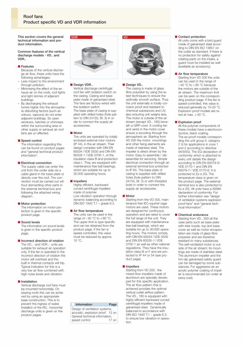
■ Design VDR..Vertical discharge centrifugalroof fan with isolation switch onthe casing. Casing and baseplate made of galvanised steel.The fans are factory-wired withthe isolation switch.The base plate of casing is sup-plied with drilled holes (hole pat-tern to DIN 24155, Bl. 3) in or-der to connect the supply airaccessories.
■ MotorThe units are operated by totallyenclosed external rotor motors(IP 44), in the air stream. Theirdesign complies with DIN EN60034 / VDE 0530 and DIN EN60335-1 / VDE 0700-1, of theinsulation class B and protectionclass I. They are equipped withmaintenance free ball bearings,which are suitable for up to30.000 operating hours.
■ ImpellersHighly efficient, backwardcurved centrifugal impellersmade of polymer.Low vibration operation throughdynamic balancing according toDIN ISO 1940 T.1 – grade 6.3.
■ Air flow temperatureThe units can be used in therange of – 40 °C to + 60 °C.The upper limit is type-specificand can be obtained from theproduct page. If the fan isspeed-controlled, this valuemust be reduced by approx.10 °C.
■ Information PageDesign of ventilation systems,acoustic, explosion proof 12 onGeneral technical information,speed control 17 on
This section covers the generaltechnical information and pro-duct information.
Common features of the verticaldischarge models - VD.. andVDR..
■ FeaturesBecause of the vertical dischar-ge air flow, these units have thefollowing advantages:
– Less impact to the environmentthrough pollution.
– Minimising the effect of the ex-haust air on the roofs, roof lightsand light domes of adjacentbuildings.
– By discharging the exhaustfumes higher into the atmosphe-re disturbing factors (such asodours, vapours) do not enteradjacent buildings. So openwindows, hatches or chimneyswithin the surrounding area orother supply or exhaust air rooffans are un affected.
■ Speed controlThe information regarding thiscan be found on product pagesand “general technical productinformation“.
■ Electrical connectionThe supply cable can enter theunit from the under side via acable gland in the base plate ordirectly over the roof. The con-nection must be carried out wit-hout dismantling other parts inthe external terminal box andfollowing the attached wiringdiagram.
■ Motor protectionThe information on motor pro-tection is given in the specificproduct page.
■ Sound levelsThe information on sound levelsis given in the specific productpage.
■ Incorrect direction of rotationThe VD..- and VDR..- units aresuitable for exhaust air operationonly. If the fan is operated in theincorrect direction of rotation themotor will overheat and thebuilt-in thermal contacts will trip.Typical indication for this is avery low air flow combined withhigh noise levels and vibration.
■ InstallationVertical discharge roof fans mustbe mounted horizontally. Onsloping roofs this can be achie-ved by using an appropriatebase construction. This is toprevent the ingress of water.Installion of the RD.. horizontaldischarge units is given on theproduct pages.
■ Design VD..The casing is made of glassfibre polyester by using the la-test techniques to ensure theoptimally smooth surface. Thusthe unit externally is totally cor-rosion proof and resistant tochemical substances and UV,also ensuring unit weighs less.The motor is outside of the airstream (except VD.. 180) bene-ath a GRP-cowl. A cooling fanand vents in the motor coverensure a recooling through theatmospheric air. Starting fromVD 200 the motor mountingsand other fixing elements aremade of stainless steel. Theimpeller is direct driven by themotor. Easy to assemble / dis-assemble for servicing. Simpleelectrical connection through anexternal terminal box protectedto IP 65. The base plate ofcasing is supplied with drilledholes (hole pattern to DIN24155, Bl. 3) or with threadedbolts in order to connect thesupply air accessories.
■ MotorStarting from the VD 200, main-tenance free IEC-squirrel cagemotors are used. These motorsare designed for continuousoperation and are rated to coverthe full range of the unit. Theyare equipped with maintenancefree ball bearings, which aresuitable for up to 30.000 opera-ting hours. The motors complywith DIN EN 60034 / VDE 0530and DIN EN 60335-1 / VDE0700-1 as well as other nationalregulations. They have the insu-lation class B or F and are pro-tected to IP 44 or 54 (see pro-duct page).
■ ImpellersStarting from VD 200.. themixed-flow impellers made ofaluminium are specially develo-ped for this specific application.The air flow pattern that isachieved provides the optimalvertical outlet airflow pattern.The VD.. 180 is equipped withhighly efficient backward curvedcentrifugal impellers made ofgalvanised steel. Dynamicallybalanced in accordance withDIN ISO 1940 T.1 – grade 6.3.to ensure low vibration in opera-tion.
■ Contact protectionAll units come with a bird guardmade of galvanised steel accor-ding to DIN EN ISO 13857 onthe outlet as standard. If there isno protection for safety againstrotating parts on the intake, aguard must be installed as well(available as accessory).
■ Air flow temperatureStarting from VD 200 the unitscan be used in the range of– 40 °C to + 90 °C becausethe motors are outside of theair stream. The maximum limitcan be seen on the correspon-ding product page. If the fan isspeed-controlled, this value isreduced generally by 10-20 °C.Explosion proof models are ra-ted at max. + 40 °C.
■ Explosion proofAll the polymer components ofthese models have a electrocon-ductive, black coating.The ex-proof models correspon-ding the unit group II, category2 G for applications in zone 1and 2 according to directive94/9/EG. The EG-declaration ofconformity which is attached toevery unit details the designaccording to DIN EN 60079-0/VDE 0170-1 and DIN EN60079-7 / VDE 0170-6. It isprotected to Ex e 2G. Thetemperature class is given onthe product page. The externalterminal box is also protected toEx e 2G. All units have a KEMAdeclaration of conformity. Forfurther information see “designof ventilation systems explosionproof fans” and “general tech-nical information”.
■ Chemical enduranceStarting from VD.. 200 all thecase parts such as base platewith inlet nozzle, top and basecover as well as motor encapsu-lation are made of glass fibrepolyester and are thereforeresistant to many substances.The self-ventilated motor is out-side of the air stream; its moun-tings are made of stainless steel.The aluminium impeller and thehot-dip galvanised safety guardcan be damaged by some sub-stances. For aggressive air anacrylic polymer coating of impel-ler is recommended (on order atextra cost).
VDVDR
Roof fansProduct specific VD and VDR information

Ro
of
fans
or directly over the roof. Con-nect following the the wiringdiagram in the terminal box (pro-tection to IP 55) located belowthe cowl.
■ Full motor protectionAll models (except explosionproof) are equipped with thermalcontacts, wired to the terminalbox. For motor overheat pro-tection connect the thermal con-tacts to the protection units asshown in the fan chart. The mo-tors of RD.. Ex are equippedwith positive temperature coeffi-cient thermistors (PTC) of win-ding (for direct temperature mo-nitoring) as standard. To providethe required motor overheat pro-tection a suitable motor trippingunit must be fitted e.g the MSAunit (accessory).
■ Explosion proofThe ex-proof models correspon-ding to unit group II, category3 G for applications in zone 2according to directive 94/9/EG.Designed according to DIN EN60079-0 / VDE 0530 and DINEN 60079-7 / VDE 0170-6.Protected to Ex e 3G. Thetemperature class is given in thefan chart. The material conformsto DIN EN 14986 as shown inthe fan chart. The motors ofRD.. Ex are equipped with posi-tive temperature coefficient ther-mistors (PTC) of winding (for di-rect temperature monitoring) asstandard. To provide the requi-red motor overheat protection asuitable motor tripping unit mustbe fitted e.g the MSA unit (ac-cessory). With these features thespeed of RD.. Ex fans can becontrolled (except RDD 225/6Ex models) where transformercontrol units TSD, TSSD canbe used. A minimum voltageof 115 V must be observed.The electrical connection is bya 80 cm long flying lead whichis attached to the motor. (A se-parate explosion proof terminalbox can be supplied as an ac-cessory). Installation and opera-tion must be in compliance withthe relevant regulations. Forfurther information see “designof ventilation systems explosionproof fans” and “general tech-nical information”.
■ Sound levelsData is given on product pagesand under “general productspecific information”.
■ Incorrect direction of rotationIf the fan is operated in the in-correct direction of rotation themotor will overheat and themotor protection will trip. Typicalindication for this is a very lowair flow combined with highnoise levels and vibration.
■ Base construction, mountingand deliverySupplied as ready to installunits. The fans can be installedquickly and easily; suitable forinstallation on all of roof con-structions. The roof curb or pur-lin should be horizontal. With themodels RD.. a slope of max. 25°is allowed. We recommend theuse of the purlin boxes and soa-ker sheets offered in the acces-sory range. Using these compo-nents minimises the cost of de-signing, completion and installa-tionl. The roof curb can also beproduced on site in concrete,wood, brick or similar. A flatsurface is necessary as a per-fect sealing with the roof. Aftermounting the unit, the fan baseplate is secured by 4 screws tothe base. Helios purlin box andbase attenuator with sizes 180–450 mm have a hinged mecha-nism and offer advantages forcleaning and maintenance. Withbases built on the site packingshould be used to level anyflatness imperfection.Any resulting gap between thefan’s base plate and the roof’sbase must be sealed with asealant. After tightening thescrews evenly, check if impellerrotates freely.
■ Model RDHorizontal dischargingcentrifugal fans for extraction.
■ SpecificationRobust, corrosion and weatherresistant construction. Baseplate made of galvanised steel.Cowl and protection grille madeof galvanised steel, nominalsizes 225 – 400 mm made ofaluminium. Nominal size 710mm with cowl made of glassfibre reinforced polyester. Allexplosion proof models withbase plate made of galvanisedsteel. Quiet operation throughresiliently mounted motor.Compact design with excellentweather protection.
■ MotorTotally enclosed external rotormotor with ball bearings,protected to IP 44 or IP 54 andto insulation class B or Faccording to DIN EN 60034 /VDE 0530 and DIN EN 60335-1 /VDE 0700-1. The windings areadditionally impregnated to pro-tect against high humidity. Theball bearings are greased for arunning time of up to 30.000running hours and are thusmaintenance free. Motor andimpeller are balanced as the unitaccording to DIN ISO 1940 T. 1– class 6.3 to ensure a low vi-bration operation..
■ ImpellersHigh performance, efficiencyoptimised backward curvedcentrifugal impellers, made ofgalvanised steel. Pressed onmotor and balanced as unit.
■ Contact safetyAll units come with a bird guardto DIN EN ISO 13857 on theoutlet as standard. If there isno ducting connected, then forsafety protection against rotatingparts on the intake, a guardmust be installed as well (availa-ble as accessory).
■ Air flow temperatureThe operating range is between– 40 to + 60 °C. Thermalcontacts protect against highertemperatures. For higher air flowtemperatures the vertical disch-arge model VD can be used.
■ Speed controlAll single speed RD fans (exceptRDD 225/6 Ex and RDD 710/6)are 100% speed controllable.For suitable controllers see charton individual fan page. Furtherinformation see “generaltechnical information”.
■ Electric wiringThe supply cable can enter theunit from the under side viacable gland in the base plate
RD
■ Information PageDesign of ventilation systems,acoustic, explosion proof 12 onGeneral technical information,speed control 17 on
Roof fansProduct specific RD information

180180200200
2500 50 0.128 0.114 0.094 0.078 0.061 0.0421700 42 0.078 0.056 0.039 0.0222650 60 0.314 0.294 0.272 0.247 0.219 0.189 0.158 0.122 0.081 0.0422600 50 0.214 0.186 0.158 0.128 0.094 0.061 0.025
334
2900 67 0.722 0.694 0.672 0.642 0.614 0.575 0.550 0.525 0.494 0.450 0.406 0.361 0.3001400 51 0.347 0.294 0.231 0.136
900 42 0.235 0.164700 36 0.186
With the combination parameters; static pressure increase Δpstat.,air flow volume V
., revolution per minute min-1, noise level in 4 m distance,
impeller diameter DN mm the following chart makes the selection of rooffans ø 180 to 710 easier.
710710710710
630630630630
560560560560
450450450450450450
400400400400400400
mm
Diameter
min-1 LPA dB(A) (Δpstat.) in Pain 4 m distance 0 50 100 150 200 250 300 350 400 450 500 550 600 650 700 750 800 850
R.P.M. Sound pressure Air flow volume V· in m3/s against static pressure = N / m2 (Pa.) external pressureintake
315315315315
225225225225225225
560560560560
500500500500
400400400
450450450
315315315
200200200200
250250250
225225225225
180180
2300 60 0.253 0.236 0.217 0.197 0.178 0.157 0.125 0.110 0.0751400 45 0.136 0.097 0.047
2900 71 0.947 0.917 0.894 0.867 0.833 0.800 0.767 0.753 0.717 0.675 0.625 0.611 0.556 0.486 0.444 0.347 0.2971400 56 0.500 0.456 0.408 0.317 0.194
900 46 0.326 0.236700 41 0.292 0.131
1400 60 0.778 0.728 0.664 0.586 0.500 0.369900 49 0.522 0.428 0.283700 45 0.394 0.267
1400 63 1.044 0.972 0.900 0.819 0.725 0.606 0.425 0.200900 53 0.708 0.600 0.458 0.175700 46 0.556 0.386
1400 70 2.222 2.139 2.067 1.986 1.875 1.769 1.650 1.500 1.354 1.150 0.925 0.472900 60 1.486 1.361 1.208 1.035 0.792 0.422700 54 1.132 0.931 0.660 0.208
1400 66 1.458 1.389 1.294 1.222 1.097 0.978 0.850 0.700 0.528 0.306900 57 0.956 0.833 0.683 0.469 0.133700 48 0.711 0.522 0.194
1400 75 3.778 3.653 3.528 3.417 3.278 3.150 3.000 2.850 2.711 2.600 2.450 2.222 2.119 1.944 1.650 1.389 1.000900 65 2.361 2.194 2.028 1.850 1.658 1.400 1.072 0.600700 60 1.736 1.611 1.389 1.083 0.544350 44 0.872 0.369
1400 79 5.306 5.278 5.167 5.028 4.917 4.800 4.700 4.550 4.450 4.300 4.194 3.944 3.889 3.806 3.550 3.278 3.150900 70 3.667 3.528 3.361 3.194 2.944 2.700 2.350 2.000 1.550 1.050700 63 3.139 2.775 2.361 1.986 1.600 1.131 0.481350 48 1.500 0.731
1420 48 0.478 0.428 0.378 0.319 0.1861380 48 0.467 0.414 0.361 0.297 0.1031260 46 0.433 0.372 0.311 0.211
950 38 0.317 0.247910 37 0.306 0.225720 31 0.236 0.078
1400 58 1.339 1.264 1.192 1.122 1.053 0.981 0.889 0.758 0.533 0.1111220 55 1.200 1.108 1.019 0.933 0.836 0.711 0.522 0.247
890 47 0.856 0.739 0.622 0.425700 41 0.689 0.519 0.264
1420 61 1.883 1.808 1.733 1.653 1.567 1.475 1.378 1.275 1.161 1.019 0.750 0.2061330 60 1.786 1.703 1.617 1.525 1.425 1.322 1.211 1.092 0.942 0.656 0.2581250 58 1.697 1.606 1.508 1.403 1.292 1.175 1.050 0.900 0.636 0.275 0.014
850 48 1.158 1.022 0.867 0.686 0.275690 43 0.914 0.744 0.522600 40 0.836 0.592 0.258
1350 63 2.536 2.439 2.339 2.239 2.136 2.028 1.919 1.808 1.697 1.583 1.456 1.303 1.017 0.428 0.1001260 63 2.400 2.292 2.183 2.094 1.953 1.833 1.708 1.583 1.450 1.300 1.094 0.700 0.356 0.0971100 59 2.142 2.014 1.881 1.742 1.592 1.439 1.286 1.114 0.861 0.519 0.281 0.081
930 53 1.728 1.589 1.442 1.289 1.125 0.919 0.317780 49 1.497 1.317 1.119 0.908 0.594 0.125660 45 1.239 1.036 0.803 0.319
920 60 3.528 3.317 3.108 2.903 2.694 2.472 2.228 1.933 1.542 0.833700/6 54 2.839 2.522 2.206 1.881 1.506 1.022 0.458700/8 54 2.658 2.383 2.114 1.825 1.458 0.772
470 42 1.767 1.361 0.808
880 63 4.667 4.447 4.225 4.000 3.764 3.517 3.250 2.956 2.619 2.197 1.536 0.722 0.142680 57 3.769 3.439 3.097 2.728 2.342 1.942 1.347 0.606 0.286 0.031650 55 3.469 3.169 2.858 2.517 2.125 1.597 0.611440 45 2.314 1.858 1.275 0.072
950 68 6.867 6.631 6.400 6.178 5.958 5.750 5.542 5.331 5.103 4.850 4.553 4.194 3.764 3.261 2.683 1.844940 72 9.583 9.314 9.047 8.786 8.533 8.286 8.044 7.808 7.567 7.319 7.053 6.764 6.436 6.056 5.614 5.100 4.522 3.867660 59 4.869 4.511 4.169 3.847 3.500 3.067 2.469 1.681480 50 3.436 2.997 2.572 1.919
Model VD – vertical discharge
Model RD – horizontal discharge
Model VDR – vertical discharge
Selection chartRoof fans

335
Ro
of
fans
Commercial ductsStandard duct sizes to suitHelios components availablefrom various stockists.
➊Centrifugal roof fan RDHorizontal dischargeCost effective.A compact, low profile design withrain protection hood.
➋Centrifugal roof fan VDVertical dischargeMotor located outside the air stream. All thecasing parts are made of glass fibre polyester,thus fully corrosion proof and UV-resistant.
➌Centrifugal roof fan VDRVertical dischargeCost effective for smaller air flow volumes.Built-on isolation switch as standard.
➍Soaker sheet WDSFor roof fans and roof cowls on profiled roofs.Weather resistant and corrosion-free made ofglass fibre reinforced polyester.Slanting roof base SDS (Page 360)For roof fans and roof cowls on slanting andsloped roofs. Inner surface of the upstand islined with sound and thermal insulation.
➎Purlin box FDSFor low priced and efficient mounting of rooffans and roof cowls on flat roofs. Made ofcorrosion resistant glass fibre reinforcedpolyester or galvanised steel. Sizes 180 to450 mm are with hinged mechanism forsimple inspection and cleaning.
➏Base attenuator SSDFor sound insulation on intake of the fan.All metal parts made of galvanised steel.Incl. fixing screws, profile rubber and sealingbetween base and base plate.Sizes 180 to 450 mm with hinged mechanismand foamed material core. Allows access toducting or ventilation shaft.
Backdraught shutterPrevents backdraughts, lossof energy and prevents-draughts. Automatic RVS
– Motorised RVMWith built-on spring reversingmotor (outside the air stream).
Flanged flexible sleeve STSPrevents vibration transmissionto the ducting.
Flange FRMade of galvanisedsteel.For connectionto ducting.
➍➎ ➏
➊ ➋ ➌
Inlet bell mouth with guardASD-SGDOptimal design with largeintake diameter and flange.
Guard SGSpot welded zinc platedwire mesh (8 mm).
Roof fans and mounting accessoriesSystem configuration

Model VDR
336
180 mm ø Centrifugal roof fans
Vertical plastic VD
■ SpecificationRoof fan with vertical dischargemade of glass-fibre reinforcedpolymer.
■ CasingThe upper and lower shell, motorprotection cover and base platewith inlet cone are made of glass-fibre polyester. Base plate withthreaded bolt for connection ofintake air accessories.
■ ImpellerHigh performance backwardcurved centrifugal impeller madeof galvanised steel, dynamicallybalanced with the motor unit.
■ MotorTotally enclosed external rotormotor with ball bearings, protectedto IP 44, insulated for protectionagainst moisture. Maintenance freeand radio suppressed.
■ Motor protectionThrough built-in thermal contactsconnected in series with windings.Deactivated automatically at highermotor temperature and activatedagain after cooling down.
■ Electrical connectionIn external terminal box, which islocated beneath rain cowl.
■ Protection grilleOn the outlet as standard,compliant with DIN EN ISO 13857.
■ Speed controlAdjustable between 0 – 100 %available with stepless electronicor five step control units. Forselection see the model chart.
■ Sound levelShown on the performance curvesthe sound pressure level is given indB(A) at 4 metres. The total leveland spectrum for sound pressureand sound power are given abovethe performance curves.
■ DeliveryFully assembled, ready to connectunits.
Vertical metal VDR
■ SpecificationCentrifugal roof fan with verticaldischarge.
■ CasingThe base plate, casing and otherparts made of galvanised steel.Base plate with tapped holes forconnection of intake air accesso-ries.
■ ImpellerHigh performance backward cur-ved centrifugal impeller made ofpolymer, dynamically balanced withthe motor unit.
■ MotorTotally enclosed external rotormotor with ball bearings, protectedto IP 44, insulated for protectionagainst moisture. Maintenance freeand radio suppressed.
■ Motor protectionThrough built-in thermal contactsconnected in series with windings.Deactivated automatically at highermotor temperature and activatedagain after cooling down.
■ Electrical connectionIsolation switch on the casing asstandard, factory-wired.
■ Speed controlAdjustable between 0 – 100 %available with stepless electronicor five step control units. Forselection see the model chart.
■ Sound levelShown on the performance curvesthe sound pressure level is given indB(A) at 4 metres. The total leveland spectrum for sound pressureand sound power are given abovethe performance curves.
■ DeliveryFully assembled, ready to connectunits.
Dimensions in mm Dimensions in mm
Flange ringsFR 180 Ref. No. 1200
Corrugated roof base, profile 5WDS 180 Ref. No. 1559
Flanged canvas connectorSTS 180 Ref. No. 1217
Automatic backdraught shutterDVS 180 Ref. No. 1247
Hinged base attenuatorSSD 180 Ref. No. 5289
Hinged flat roof baseFDS 180 Ref. No. 1377
Dimensions in mm
Model VD
Accessories for VD and VDRW
■ Information PageDesign of systems 12 onTechnical specification 332Selection chart 334Accessories, details 359Speed controllers, controllersand switches 397 on

333
Ro
of
fans
or directly over the roof. Con-nect following the the wiringdiagram in the terminal box (pro-tection to IP 55) located belowthe cowl.
■ Full motor protectionAll models (except explosionproof) are equipped with thermalcontacts, wired to the terminalbox. For motor overheat pro-tection connect the thermal con-tacts to the protection units asshown in the fan chart. The mo-tors of RD.. Ex are equippedwith positive temperature coeffi-cient thermistors (PTC) of win-ding (for direct temperature mo-nitoring) as standard. To providethe required motor overheat pro-tection a suitable motor trippingunit must be fitted e.g the MSAunit (accessory).
■ Explosion proofThe ex-proof models correspon-ding to unit group II, category3 G for applications in zone 2according to directive 94/9/EG.Designed according to DIN EN60079-0 / VDE 0530 and DINEN 60079-7 / VDE 0170-6.Protected to Ex e 3G. Thetemperature class is given in thefan chart. The material conformsto DIN EN 14986 as shown inthe fan chart. The motors ofRD.. Ex are equipped with posi-tive temperature coefficient ther-mistors (PTC) of winding (for di-rect temperature monitoring) asstandard. To provide the requi-red motor overheat protection asuitable motor tripping unit mustbe fitted e.g the MSA unit (ac-cessory). With these features thespeed of RD.. Ex fans can becontrolled (except RDD 225/6Ex models) where transformercontrol units TSD, TSSD canbe used. A minimum voltageof 115 V must be observed.The electrical connection is bya 80 cm long flying lead whichis attached to the motor. (A se-parate explosion proof terminalbox can be supplied as an ac-cessory). Installation and opera-tion must be in compliance withthe relevant regulations. Forfurther information see “designof ventilation systems explosionproof fans” and “general tech-nical information”.
■ Sound levelsData is given on product pagesand under “general productspecific information”.
■ Incorrect direction of rotationIf the fan is operated in the in-correct direction of rotation themotor will overheat and themotor protection will trip. Typicalindication for this is a very lowair flow combined with highnoise levels and vibration.
■ Base construction, mountingand deliverySupplied as ready to installunits. The fans can be installedquickly and easily; suitable forinstallation on all of roof con-structions. The roof curb or pur-lin should be horizontal. With themodels RD.. a slope of max. 25°is allowed. We recommend theuse of the purlin boxes and soa-ker sheets offered in the acces-sory range. Using these compo-nents minimises the cost of de-signing, completion and installa-tionl. The roof curb can also beproduced on site in concrete,wood, brick or similar. A flatsurface is necessary as a per-fect sealing with the roof. Aftermounting the unit, the fan baseplate is secured by 4 screws tothe base. Helios purlin box andbase attenuator with sizes 180–450 mm have a hinged mecha-nism and offer advantages forcleaning and maintenance. Withbases built on the site packingshould be used to level anyflatness imperfection.Any resulting gap between thefan’s base plate and the roof’sbase must be sealed with asealant. After tightening thescrews evenly, check if impellerrotates freely.
■ Model RDHorizontal dischargingcentrifugal fans for extraction.
■ SpecificationRobust, corrosion and weatherresistant construction. Baseplate made of galvanised steel.Cowl and protection grille madeof galvanised steel, nominalsizes 225 – 400 mm made ofaluminium. Nominal size 710mm with cowl made of glassfibre reinforced polyester. Allexplosion proof models withbase plate made of galvanisedsteel. Quiet operation throughresiliently mounted motor.Compact design with excellentweather protection.
■ MotorTotally enclosed external rotormotor with ball bearings,protected to IP 44 or IP 54 andto insulation class B or Faccording to DIN EN 60034 /VDE 0530 and DIN EN 60335-1 /VDE 0700-1. The windings areadditionally impregnated to pro-tect against high humidity. Theball bearings are greased for arunning time of up to 30.000running hours and are thusmaintenance free. Motor andimpeller are balanced as the unitaccording to DIN ISO 1940 T. 1– class 6.3 to ensure a low vi-bration operation..
■ ImpellersHigh performance, efficiencyoptimised backward curvedcentrifugal impellers, made ofgalvanised steel. Pressed onmotor and balanced as unit.
■ Contact safetyAll units come with a bird guardto DIN EN ISO 13857 on theoutlet as standard. If there isno ducting connected, then forsafety protection against rotatingparts on the intake, a guardmust be installed as well (availa-ble as accessory).
■ Air flow temperatureThe operating range is between– 40 to + 60 °C. Thermalcontacts protect against highertemperatures. For higher air flowtemperatures the vertical disch-arge model VD can be used.
■ Speed controlAll single speed RD fans (exceptRDD 225/6 Ex and RDD 710/6)are 100% speed controllable.For suitable controllers see charton individual fan page. Furtherinformation see “generaltechnical information”.
■ Electric wiringThe supply cable can enter theunit from the under side viacable gland in the base plate
RD
■ Information PageDesign of ventilation systems,acoustic, explosion proof 12 onGeneral technical information,speed control 17 on
Roof fansProduct specific RD information

332
■ Design VDR..Vertical discharge centrifugalroof fan with isolation switch onthe casing. Casing and baseplate made of galvanised steel.The fans are factory-wired withthe isolation switch.The base plate of casing is sup-plied with drilled holes (hole pat-tern to DIN 24155, Bl. 3) in or-der to connect the supply airaccessories.
■ MotorThe units are operated by totallyenclosed external rotor motors(IP 44), in the air stream. Theirdesign complies with DIN EN60034 / VDE 0530 and DIN EN60335-1 / VDE 0700-1, of theinsulation class B and protectionclass I. They are equipped withmaintenance free ball bearings,which are suitable for up to30.000 operating hours.
■ ImpellersHighly efficient, backwardcurved centrifugal impellersmade of polymer.Low vibration operation throughdynamic balancing according toDIN ISO 1940 T.1 – grade 6.3.
■ Air flow temperatureThe units can be used in therange of – 40 °C to + 60 °C.The upper limit is type-specificand can be obtained from theproduct page. If the fan isspeed-controlled, this valuemust be reduced by approx.10 °C.
■ Information PageDesign of ventilation systems,acoustic, explosion proof 12 onGeneral technical information,speed control 17 on
This section covers the generaltechnical information and pro-duct information.
Common features of the verticaldischarge models - VD.. andVDR..
■ FeaturesBecause of the vertical dischar-ge air flow, these units have thefollowing advantages:
– Less impact to the environmentthrough pollution.
– Minimising the effect of the ex-haust air on the roofs, roof lightsand light domes of adjacentbuildings.
– By discharging the exhaustfumes higher into the atmosphe-re disturbing factors (such asodours, vapours) do not enteradjacent buildings. So openwindows, hatches or chimneyswithin the surrounding area orother supply or exhaust air rooffans are un affected.
■ Speed controlThe information regarding thiscan be found on product pagesand “general technical productinformation“.
■ Electrical connectionThe supply cable can enter theunit from the under side via acable gland in the base plate ordirectly over the roof. The con-nection must be carried out wit-hout dismantling other parts inthe external terminal box andfollowing the attached wiringdiagram.
■ Motor protectionThe information on motor pro-tection is given in the specificproduct page.
■ Sound levelsThe information on sound levelsis given in the specific productpage.
■ Incorrect direction of rotationThe VD..- and VDR..- units aresuitable for exhaust air operationonly. If the fan is operated in theincorrect direction of rotation themotor will overheat and thebuilt-in thermal contacts will trip.Typical indication for this is avery low air flow combined withhigh noise levels and vibration.
■ InstallationVertical discharge roof fans mustbe mounted horizontally. Onsloping roofs this can be achie-ved by using an appropriatebase construction. This is toprevent the ingress of water.Installion of the RD.. horizontaldischarge units is given on theproduct pages.
■ Design VD..The casing is made of glassfibre polyester by using the la-test techniques to ensure theoptimally smooth surface. Thusthe unit externally is totally cor-rosion proof and resistant tochemical substances and UV,also ensuring unit weighs less.The motor is outside of the airstream (except VD.. 180) bene-ath a GRP-cowl. A cooling fanand vents in the motor coverensure a recooling through theatmospheric air. Starting fromVD 200 the motor mountingsand other fixing elements aremade of stainless steel. Theimpeller is direct driven by themotor. Easy to assemble / dis-assemble for servicing. Simpleelectrical connection through anexternal terminal box protectedto IP 65. The base plate ofcasing is supplied with drilledholes (hole pattern to DIN24155, Bl. 3) or with threadedbolts in order to connect thesupply air accessories.
■ MotorStarting from the VD 200, main-tenance free IEC-squirrel cagemotors are used. These motorsare designed for continuousoperation and are rated to coverthe full range of the unit. Theyare equipped with maintenancefree ball bearings, which aresuitable for up to 30.000 opera-ting hours. The motors complywith DIN EN 60034 / VDE 0530and DIN EN 60335-1 / VDE0700-1 as well as other nationalregulations. They have the insu-lation class B or F and are pro-tected to IP 44 or 54 (see pro-duct page).
■ ImpellersStarting from VD 200.. themixed-flow impellers made ofaluminium are specially develo-ped for this specific application.The air flow pattern that isachieved provides the optimalvertical outlet airflow pattern.The VD.. 180 is equipped withhighly efficient backward curvedcentrifugal impellers made ofgalvanised steel. Dynamicallybalanced in accordance withDIN ISO 1940 T.1 – grade 6.3.to ensure low vibration in opera-tion.
■ Contact protectionAll units come with a bird guardmade of galvanised steel accor-ding to DIN EN ISO 13857 onthe outlet as standard. If there isno protection for safety againstrotating parts on the intake, aguard must be installed as well(available as accessory).
■ Air flow temperatureStarting from VD 200 the unitscan be used in the range of– 40 °C to + 90 °C becausethe motors are outside of theair stream. The maximum limitcan be seen on the correspon-ding product page. If the fan isspeed-controlled, this value isreduced generally by 10-20 °C.Explosion proof models are ra-ted at max. + 40 °C.
■ Explosion proofAll the polymer components ofthese models have a electrocon-ductive, black coating.The ex-proof models correspon-ding the unit group II, category2 G for applications in zone 1and 2 according to directive94/9/EG. The EG-declaration ofconformity which is attached toevery unit details the designaccording to DIN EN 60079-0/VDE 0170-1 and DIN EN60079-7 / VDE 0170-6. It isprotected to Ex e 2G. Thetemperature class is given onthe product page. The externalterminal box is also protected toEx e 2G. All units have a KEMAdeclaration of conformity. Forfurther information see “designof ventilation systems explosionproof fans” and “general tech-nical information”.
■ Chemical enduranceStarting from VD.. 200 all thecase parts such as base platewith inlet nozzle, top and basecover as well as motor encapsu-lation are made of glass fibrepolyester and are thereforeresistant to many substances.The self-ventilated motor is out-side of the air stream; its moun-tings are made of stainless steel.The aluminium impeller and thehot-dip galvanised safety guardcan be damaged by some sub-stances. For aggressive air anacrylic polymer coating of impel-ler is recommended (on order atextra cost).
VDVDR
Roof fansProduct specific VD and VDR information

339
Ro
of
fans
VDW 200/6 5137 940 845 42 0.060 0.30 563 90 11.0 MW 1579 MWS 1,53) 1947VDW 200/4 5138 1380 1250 51 0.085 0.45 563 90 11.0 MW 1579 MWS 1,53) 1947VDW 200/2 5139 2730 2600 67 0.530 2.35 508 90 12.0 w/o thermal contacts not variable
VDD 200/6 5140 930 845 42 0.046 0.19 469 90 11.0 MD 5849 RDS 13) 1314VDD 200/4 5141 1390 1250 51 0.085 0.26 469 90 11.0 MD 5849 RDS 13) 1314VDD 200/2 5142 2880 2600 67 0.620 1.20 470 90 12.0 w/o thermal contacts not variable
VDD 200/8/41) 5143 740 / 1490 670 / 1250 36 / 51 0.075 / 0.170 0.39 / 0.90 471 90 15.0 w/o thermal contacts PDA 124) 5081VDD 200/6/42) 5144 990 / 1490 845 / 1250 42 / 51 0.095 / 0.150 0.34 / 0.70 473 90 15.0 w/o thermal contacts PGWA 124) 5083
VDD 200/4 Ex 5145 1400 1250 51 0.120 0.41 470 40 12.0 w/o thermal contacts not variable
Type Ref. No.V· m3/hmin-1 dB(A) in 4 m kW Type Ref. No.kgA No.
Transformer controllerPole switch
Ref.No.
Type Air flow volume(FID)
R.P.M. Sound pressurelevel
Power consumption Motor full protectionunit
Nominalweight
Wiringdiagram
°C
Max. air flowtemperature
Frequency Hz Total 125 250 500 1k 2k 4kLPA, 4m Case breakout dB(A) 67 48 58 59 61 61 58LWA Intake dB(A) 81 62 72 74 74 75 71
VD 200/2Frequency Hz Total 125 250 500 1k 2k 4kLPA, 4m Case breakout dB(A) 51 37 40 44 47 43 37LWA Intake dB(A) 63 51 54 59 56 57 50
VD 200/4
2900 min-1
64
66
67
1400 min-1
48
49
5 1
900 min-1
40
41
42
Frequency Hz Total 125 250 500 1k 2k 4k
900min-1 LPA, 4m Case breakout dB(A) 42 27 33 37 39 31 25LWA Intake dB(A) 54 41 47 52 44 45 38
700min-1 LPA, 4m Case breakout dB(A) 36 22 25 29 32 28 22LWA Intake dB(A) 48 36 39 44 41 42 35
VD 200/6 and 200/8
Frequency Hz Total 125 250 500 1k 2k 4kLPA, 4m Case breakout dB(A) 50 19 31 42 46 45 42LWA Intake dB(A) 69 49 53 63 66 58 57
VDRW 200/2 BFrequency Hz Total 125 250 500 1k 2k 4kLPA, 4m Case breakout dB(A) 60 31 42 55 53 53 47LWA Intake dB(A) 79 62 63 72 77 58 61
VDRW 200/2 D
1) Dahlander-winding 2) Separate winding 3) Includes motor full protection unit 4) For the flush-mounted version see the product page - switches
700 min-1
33
34
36
➀ 230 V➁ 170 V➂ 130 V➃ 100 V➄ 80 V
59
60
➀ 230 V➁ 170 V➂ 130 V➃ 100 V➄ 80 V
51
50
➀
➁
➂➃
➄
Transformer controller5-step
Electronic speed controllerflush m. / surface m.
Ref.No.
Type Air flow volume(FID)
R.P.M. Sound pressurelevel
Power consumption Max. air flowtemperature
Nominalweight
Wiringdiagram
Type Ref. No. Type Ref. No.
VDRW 200/2 B 2795 2600 770 50 0.085 0.38 826 40 9.5 TSW 1.5 1495 ESU 1/ESA 1 0236/0238VDRW 200/2 D 2796 2650 1130 60 0.135 0.60 826 60 10.5 TSW 1.5 1495 ESU 1/ESA 1 0236/0238
V· m3/hmin-1 dB(A) in 4 m kW °C kgA No.Single speed, 230 V, 50 Hz, 1ph capacitor motor, protection to IP 44
➀
➁
➂➃
➄
Single speed, 230 V, 50 Hz, 1ph capacitor motor, protection to IP 54
Single speed, three phase alternating current 400 V, 50 Hz, squirrel-cage motor, protection to IP 54
Pole-changeable, with 2 speed motor, three phase alternating current 400 V, 50 Hz, protection to IP 54 Pole switch
Explosion proof, temperature class T1 – T3, three phase alternating current 400 V, 50 Hz, protection to IP 54
Δpstat.Pa
Δpstat.Pa
Δpstat.Pa
Δpstat.Pa
V· m3/h
ρ = 1.20 kg/m3Δpstat.Pa
V· m3/h
ρ = 1.20 kg/m3
ρ = 1.20 kg/m3 ρ = 1.20 kg/m3ρ = 1.20 kg/m3
V· m3/h V· m3/h V· m3/h
Centrifugal roof fans ø 200 mm

340
225 mm ø Centrifugal roof fans
Vertical discharge VD
■ SpecificationRoof fan with vertical dischargemade of polymer with the motorout of the air stream. Enginemountings made of stainless steel.
■ CasingThe upper and lower shell, motorprotection cover and base platewith inlet cone are made of glass-fibre polyester. Base plate withthreaded bolt for connection ofintake air accessories.
■ ImpellerHigh performance backward cur-ved centrifugal impeller made ofaluminium, dynamically balanced.
■ MotorTotally enclosed IEC-motor withsurface cooling protected to IP 54,ball bearing mounted, insulated forprotection against moisture.Maintenance free and radio sup-pressed.
■ Motor protectionAll variable models (except modelswith pole switch) have built-inthermal contacts which must beconnected to the motor full pro-tection unit (see model chart) inorder to protect the motor effecti-vely.
■ Electrical connectionDirectly from the roof in to theexternal terminal box protectedto IP 65.
■ Protection grilleOn the outlet as standard,compliant with DIN EN ISO 13857.
■ Speed controlAll models where a speed control-ler is shown on the table are speedcontrollable via voltage reduction(1 ph. models electronically aswell). Also two speed models areavailable.
■ Sound levelShown on the performance curvesthe sound pressure level is given indB(A) at 4 metres. The total leveland spectrum for sound pressureand sound power are given abovethe performance curves.
■ DeliveryFully assembled, ready to connectunits.
Horizontal discharge RD
■ SpecificationCentrifugal roof fan with horizontaldischarge. Flat design with largeoverlaying rain cowl.
■ CasingBase plate (with inlet cone) andother parts made of galvanisedsteel. Rain cowl and protectiongrille made of aluminium. Baseplate with threaded bolt forconnection of intake air accesso-ries.
■ ImpellerHigh performance backwardcurved centrifugal impeller madeof galvanised steel, dynamicallybalanced with the motor unit.
■ MotorTotally enclosed external rotormotor with ball bearings, protectedto IP 44, insulated for protectionagainst moisture. Maintenance freeand radio suppressed.
■ Motor protectionThrough built-in thermal contactswhich must be connected to themotor full protection unit.Explosion proof models are equip-ped with thermal motor protectionthrough built-in PTC thermistorwhich is connected to the trippingunit MSA. Hereby speed control isallowed where the minimum voltagemust not be less than 115 V.
■ Electrical connectionTerminal box (protection to IP 55)located beneath rain cowl as stan-dard. The explosion proof modelsare supplied with a 80 cm longconnection lead. Explosion proofterminal box is available as acces-sory (KK Ex, Ref. No. 6862).
■ Protection grilleOn the outlet as standard,compliant with DIN EN ISO 13857.
■ Speed controlAll models where a speed control-ler is shown on the table are speedcontrollable via voltage reduction(1 ph. models electronically aswell). Also two speed models areavailable.
■ Sound levelShown on the performance curvesthe sound pressure level is given indB(A) at 4 metres. The total leveland spectrum for sound pressureand sound power are given abovethe performance curves.
■ DeliveryFully assembled, ready to connectunits.
Dimensions in mm Dimensions in mm
Flange ringsFR 225 Ref. No. 1201
Corrugated roof base, profile 5WDS 225 Ref. No. 1560
Flanged canvas connectorSTS 225 Ref. No. 1218For explosion proof fansSTS 225 Ex Ref. No. 2500
Automatic backdraught shutterRVS 225 Ref. No. 2591
Motorised backdraught shutterRVM 225 Ref. No. 2575
Hinged base attenuatorSSD 225 Ref. No. 5290
Hinged flat roof baseFDS 225 Ref. No. 1378
Dim. in mm
Roof fan attenuatorHSDV 225 Ref. No. 6757only for RD..
Horizontal discharge RDVertical discharge VD
Accessories for VD and RD
■ Information PageDesign of systems 12 onTechnical specification 332Selection chart 334Accessories, details 359Speed controllers, controllersand switches 397 on
341
Ro
of
fans
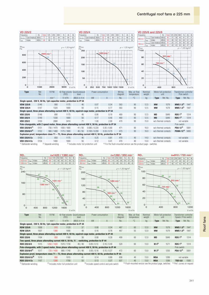
Frequency Hz Total 125 250 500 1k 2k 4kLPA, 4m Case breakout dB(A) 71 53 63 64 66 64 63LWA Intake dB(A) 84 68 77 79 77 78 74
VD 225/2Frequency Hz Total 125 250 500 1k 2k 4kLPA, 4m Case breakout dB(A) 56 40 46 50 51 48 43LWA Intake dB(A) 69 55 60 65 61 62 54
VD 225/4
2900 min-1
69
70
71
1400 min-1
53
55
56
43
45
46
VD 225/6 and 225/8
1) Dahlander-winding 2) Separate winding 3) Includes motor full protection unit 4) For the flush-mounted version see the product page - switches
RD.. n=1420 / 1380 min-1 RD.. n=1260 / 950 min-1
1420 min-1
1380 min-1
4745
48
51
4644
47
46
47
50
1260 min-1
950 min-1
42
44
44
46
48
36
36
34
38
40
910 min-1
3739
37
39
36
27
29
31
29
33
RD.. n=910 / 720 min-1
900 min-1
700 min-1
38
40
41
Frequency Hz Total 125 250 500 1k 2k 4k
900min-1 LPA, 4m Case breakout dB(A) 46 31 38 40 41 37 31LWA Intake dB(A) 59 46 52 55 50 51 42
700min-1 LPA, 4m Case breakout dB(A) 41 25 31 35 36 33 28LWA Intake dB(A) 54 40 45 50 46 47 39
1) Dahlander-winding 2) Includes motor full protection unit 3) Includes speed control and pole switch 4) Flush-mounted version see the product page, switches 5) Perf. curves on request
Frequency Hz Total 125 250 500 1k 2k 4k1420 min-1 LWA Intake dB(A) 68 63 58 60 61 59 521380 min-1 LWA Intake dB(A) 67 62 57 59 60 58 51
Frequency Hz Total 125 250 500 1k 2k 4k1260 min-1 LWA Intake dB(A) 66 61 56 58 59 57 50950 min-1 LWA Intake dB(A) 58 53 48 50 51 48 42
Type Ref. No.V· m3/hmin-1 dB(A) in 4 m kW Type Ref. No.kgA No.
Transformer controllerPole switch
Ref.No.
Type Air flow volume(FID)
R.P.M. Sound pressurelevel
Power consumption Motor full protectionunit
Nominalweight
Wiringdiagram
°C
Max. air flowtemperature
VDW 225/6 5146 900 1175 46 0.07 0.34 563 90 12.5 MW 1579 MWS 1.53) 1947VDW 225/4 5147 1320 1800 56 0.15 0.77 563 90 12.5 MW 1579 MWS 1.53) 1947
VDD 225/6 5148 890 1175 46 0.06 0.19 469 90 12.5 MD 5849 RDS 13) 1314VDD 225/4 5149 1330 1800 56 0.17 0.40 469 90 12.5 MD 5849 RDS 13) 1314VDD 225/2 5150 2880 3410 71 1.00 2.00 470 90 15.0 w/o thermal contacts not variable
VDD 225/8/41) 5151 730 / 1470 1050 / 1800 41 / 56 0.085 / 0.220 0.35 / 0.80 471 90 16.0 w/o thermal contacts PDA 124) 5081VDD 225/6/42) 5152 980 / 1480 1175 / 1800 46 / 56 0.100 / 0.200 0.33 / 0.75 473 90 16.0 w/o thermal contacts PGWA 124) 5083
VDD 225/4 Ex 5154 1400 1800 56 0.12 0.41 470 40 13.0 w/o thermal contacts not variableVDD 225/6 Ex 5153 850 1175 46 0.25 0.81 470 40 14.0 w/o thermal contacts not variable
Single speed, 230 V, 50 Hz, 1ph capacitor motor, protection to IP 54
Single speed, three phase alternating current 400 V, 50 Hz, squirrel-cage motor, protection to IP 54
Pole-changeable, with 2 speed motor, three phase alternating current 400 V, 50 Hz, protection to IP 54 Pole switch
Explosion proof, temperature class T1 – T3, three phase alternating current 400 V, 50 Hz, protection to IP 54
Type Ref. No.V· m3/hmin-1 dB(A) in 4 m kW Type Ref. No.kgA No.
Transformer controllerSpeed-/ Pole switch
Ref.No.
Type Air flow volume(FID)
R.P.M. Sound pressurelevel
Power consumption Motor full protectionunit
Nominalweight
Wiringdiagram
°C
Max. air flowtemperature
RDW 225/6 1508 910 1120 37 0.08 0.34 467 60 12.0 MW 1579 MWS 1.52) 1947RDW 225/4 1507 1380 1690 48 0.16 0.76 467 55 12.0 MW 1579 MWS 1.52) 1947
RDD 225/6 1164 950 1160 38 0.08 0.28 499 60 12.0 MD 5849 RDS 12) 1314
RDD 225/8/41) 1517 720 / 1430 880 / 1740 31 / 48 0.05 / 0.16 0.15 / 0.37 472 60 13.0 M 33) 1293 PDA 124) 5081
RDD 225/6 Ex5) 1519 990 1015 41 0.14 0.89 838 40 13.0 MSA 1289 not variableRDD 225/4 Ex 1167 1390 1700 50 0.13 0.37 837 40 13.0 MSA 1289 TSD 0.8 1500
RDD 225/4/4 1515 1260 / 1420 1570 / 1730 46 / 48 0.09 / 0.13 0.16 / 0.40 520 60 13.0 M 43) 1571 RDS 12) 1314
Explosion proof, temperature class T1 – T3, three phase alternating current 400 V, 50 Hz, protection to IP 44
Single speed, 230 V, 50 Hz, 1ph capacitor motor, protection to IP 44
Single speed, three phase alternating current 400 V, 50 Hz, squirrel-cage motor, protection to IP 44
Two speed, three phase alternating current 400 V, 50 Hz, Y/▲▲-switching, protection to IP 44
Pole-changeable, with 2 speed motor, three phase alternating current 400 V, 50 Hz, protection to IP 44 Pole switch
720 min-1
Frequency Hz Total 125 250 500 1k 2k 4k910 min-1 LWA Intake dB(A) 57 52 47 49 50 47 41720 min-1 LWA Intake dB(A) 51 46 41 43 44 42 35
Δpstat.Pa
Δpstat.Pa
Δpstat.Pa
Δpstat.Pa
Δpstat.Pa
Δpstat.Pa
ρ = 1.20 kg/m3 ρ = 1.20 kg/m3ρ = 1.20 kg/m3
ρ = 1.20 kg/m3 ρ = 1.20 kg/m3 ρ = 1.20 kg/m3
V· m3/h V· m3/h V· m3/h
V· m3/h V· m3/h V· m3/h
Centrifugal roof fans ø 225 mm

342
250 mm ø Centrifugal roof fans
■ Electrical connectionDirectly from the roof in to theexternal terminal box protected toIP 65.
■ Protection grilleOn the outlet as standard,compliant with DIN EN ISO 13857.
■ Speed controlAll models where a speed control-ler is shown on the table are speedcontrollable via voltage reduction (1 ph. models electronically aswell). Two speed models are alsoavailable.
■ Sound levelShown on the performance curvesthe sound pressure level is given indB(A) at 4 metres. The total leveland spectrum for sound pressureand sound power are given abovethe performance curves.
■ DeliveryFully assembled, ready to connectunits.
Dimensions in mm
Dimensions in mm
Dimensions for the base on site
■ SpecificationRoof fan with vertical dischargemade of polymer with the motorout of the air stream. Enginemountings made of stainless steel.
■ CasingThe upper and lower shell, motorprotection cover and base platewith inlet cone made of glass-fibrepolyester. Base plate with threadedbolt for connection of intake airaccessories.
■ ImpellerHigh performance backward cur-ved centrifugal impeller made ofaluminium, dynamically balanced.
■ MotorTotally enclosed IEC-motor withsurface cooling protected to IP 54,ball bearing mounted, insulated forprotection against moisture.Maintenance free and radio sup-pressed.
■ Motor protectionAll variable models (except modelswith pole switch) have built-inthermal contacts which must beconnected to the motor full pro-tection unit (see model chart) inorder to protect the motor effecti-vely.
Flange ringsFR 250 Ref. No. 1203
Corrugated roof base, profile 5WDS 250 Ref. No. 1561
Flanged canvas connectorSTS 250 Ref. No. 1220For explosion proof fansSTS 250 Ex Ref. No. 2501
Automatic backdraught shutterRVS 250 Ref. No. 2592
Motorised backdraught shutterRVM 250 Ref. No. 2576
Hinged base attenuatorSSD 250 Ref. No. 5292
Hinged flat roof baseFDS 250 Ref. No. 1379
Dimensions in mm
Vertical discharge VD
Accessories for VD
■ Information PageDesign of systems 12 on Technical specification 332 Selection chart 334Accessories, details 359 Speed controllers, controllersand switches 397 on
hole for electrical connection

343
Ro
of
fans
Frequency Hz Total 125 250 500 1k 2k 4kLPA, 4m Case breakout dB(A) 60 44 50 54 55 63 49LWA Intake dB(A) 74 60 63 69 67 68 60
VD 250/4Frequency Hz Total 125 250 500 1k 2k 4kLPA, 4m Case breakout dB(A) 49 32 40 43 45 40 34LWA Intake dB(A) 62 48 53 58 54 55 45
VD 250/6
1400 min-1
57
59
60
900 min-1
46
48
49
45
Frequency Hz Total 125 250 500 1k 2k 4kLPA, 4m Case breakout dB(A) 45 28 37 41 39 33 26LWA Intake dB(A) 58 44 50 56 47 48 37
VD 250/8
42
4 3
700 min-1
1) Dahlander-winding 2) Separate winding 3) Includes motor full protection unit 4) For the flush-mounted version see the product page - switches
Type Ref. No.V· m3/h min-1 dB(A) in 4 m kW Type Ref. No.kgA No.
Transformer controllerPole switch
Ref.No.
Type Air flow volume(FID)
R.P.M. Sound pressurelevel
Power consumption Motor full protectionunit
Nominalweight
Wiringdiagram
°C
Max. air flowtemperature
VDW 250/6 5155 920 1880 49 0.11 0.61 563 90 16.0 MW 1579 MWS 1.53) 1947VDW 250/4 5156 1320 2800 60 0.23 1.06 563 90 14.5 MW 1579 MWS 1.53) 1947
VDD 250/6 5158 940 1880 49 0.11 0.35 469 90 14.5 MD 5849 RDS 13) 1314VDD 250/4 5159 1390 2800 60 0.28 0.63 469 90 14.5 MD 5849 RDS 13) 1314
VDD 250/8/41) 5161 740 / 1470 1420 / 2800 45 / 60 0.095 / 0.330 0.39 / 0.90 471 90 17.0 w/o thermal contacts PDA 124) 5081VDD 250/6/42) 5162 970 / 1470 1880 / 2800 49 / 60 0.130 / 0.280 0.34 / 0.77 473 90 17.0 w/o thermal contacts PGWA 124) 5083
VDD 250/4 Ex 5164 1355 2800 60 0.37 1.10 470 40 15.5 w/o thermal contacts not variableVDD 250/6 Ex 5163 850 1880 49 0.25 0.81 470 40 15.5 w/o thermal contacts not variable
VDD 250/8/62) 5160 730 / 960 1420 / 1880 45 / 49 0.120 / 0.120 0.32 / 0.28 473 90 19.5 w/o thermal contacts PGWA 124) 5083
Single speed, three phase alternating current 400 V, 50 Hz, squirrel-cage motor, protection to IP 54
Explosion proof, temperature class T1 – T3, three phase alternating current 400 V, 50 Hz, protection to IP 54
Pole-changeable, with 2 speed motor, three phase alternating current 400 V, 50 Hz, protection to IP 54 Pole switch
Single speed, 230 V, 50 Hz, 1ph capacitor motor, protection to IP 54
Δpstat.Pa
Δpstat.Pa
Δpstat.Pa
ρ = 1.20 kg/m3 ρ = 1.20 kg/m3ρ = 1.20 kg/m3
V· m3/h V· m3/h V· m3/h
Centrifugal roof fans ø 250 mm

344
315 mm ø Centrifugal roof fans
Dimensions in mm Dimensions in mm
Vertical discharge VD
■ SpecificationRoof fan with vertical dischargemade of polymer with the motorout of the air stream. Enginemountings made of stainless steel.
■ CasingThe upper and lower shell, motorprotection cover and base platewith inlet cone are made of glass-fibre polyester. Base plate withthreaded bolt for connection ofintake air accessories.
■ ImpellerHigh performance backward cur-ved centrifugal impeller made ofaluminium, dynamically balanced.
■ MotorTotally enclosed IEC-motor withsurface cooling protected to IP 54,ball bearing mounted, insulated forprotection against moisture.Maintenance free and radio sup-pressed.
■ Motor protectionAll variable models (except modelswith pole switch) have built-inthermal contacts which must beconnected to the motor full pro-tection unit (see model chart) inorder to protect the motor effecti-vely.
■ Electrical connectionDirectly from the roof in to theexternal terminal box protected toIP 65.
■ Protection grilleOn the outlet as standard,compliant with DIN EN ISO 13857.
■ Speed controlAll models where a speed control-ler is shown on the table are speedcontrollable via voltage reduction(1 ph. models electronically aswell). Two speed models are alsoavailable.
■ Sound levelShown on the performance curvesthe sound pressure level is given indB(A) at 4 metres. The total leveland spectrum for sound pressureand sound power are given abovethe performance curves.
■ DeliveryFully assembled, ready to connectunits.
Horizontal discharge RD
■ Specification Centrifugal roof fan with horizontaldischarge. Flat design with largeoverlaying rain cowl.
■ CasingBase plate (with inlet cone) andother parts made of galvanisedsteel. Rain cowl and protectiongrille made of aluminium. Baseplate with threaded bolt forconnection of intake air accesso-ries.
■ ImpellerHigh performance backwardcurved centrifugal impeller madeof galvanised steel, dynamicallybalanced with the motor unit.
■ MotorTotally enclosed external rotormotor with ball bearings, protectedto IP 44, insulated for protectionagainst moisture. Maintenance freeand radio suppressed.
■ Motor protectionThrough built-in thermal contactswhich must be connected to themotor full protection unit. Explosion proof models are equip-ped with thermal motor protectionthrough built-in PTC thermistorwhich is connected to the trippingunit MSA. Hereby speed control isallowed where the minimum voltagemust not be less than 115 V.
■ Electrical connectionTerminal box (protection to IP 55)located beneath rain cowl as stan-dard. The explosion proof modelsare supplied with a 80 cm longconnection lead. Explosion proofterminal box is available as acces-sory (KK Ex, Ref. No. 6862).
■ Protection grilleOn the outlet as standard,compliant with DIN EN ISO 13857.
■ Speed controlAll models where a speed control-ler is shown on the table are speedcontrollable via voltage reduction(1 ph. models electronically aswell). Two speed models are alsoavailable.
■ Sound levelShown on the performance curvesthe sound pressure level is given indB(A) at 4 metres. The total leveland spectrum for sound pressureand sound power are given abovethe performance curves.
■ DeliveryFully assembled, ready to connectunits.
Flange ringsFR 315 Ref. No. 1204
Corrugated roof base, profile 5WDS 315 Ref. No. 1561
Flanged canvas connectorSTS 315 Ref. No. 1221For explosion proof fansSTS 315 Ex Ref. No. 2503
Automatic backdraught shutterRVS 315 Ref. No. 2594
Motorised backdraught shutterRVM 315 Ref. No. 2578
Hinged base attenuatorSSD 315 Ref. No. 5292
Hinged flat roof baseFDS 315 Ref. No. 1379
Dim. in mm
Roof fan attenuatorHSDV 315 Ref. No. 6758only for RD..
Vertical discharge VD Horizontal discharge RD
Accessories for VD and RD
■ Information PageDesign of systems 12 on Technical specification 332 Selection chart 334Accessories, details 359 Speed controllers, controllersand switches 397 on

345
Ro
of
fans
Frequency Hz Total 125 250 500 1k 2k 4kLPA, 4m Case breakout dB(A) 63 45 53 58 58 54 50LWA Intake dB(A) 76 63 67 72 69 70 61
VD 315/4Frequency Hz Total 125 250 500 1k 2k 4kLPA, 4m Case breakout dB(A) 53 36 45 48 48 43 38LWA Intake dB(A) 66 54 59 62 58 59 49
VD 315/6
1400 min-1
59
60
6 3
900 min-1
49
51
53
700 min-1
43
44
46
Frequency Hz Total 125 250 500 1k 2k 4kLPA, 4m Case breakout dB(A) 46 29 38 42 41 37 32LWA Intake dB(A) 60 47 52 56 52 53 43
VD 315/8
1) Dahlander-winding 2) Separate winding 3) Includes motor full protection unit 4) For the flush-mounted version see the product page - switches
RD.. n=1220 min-1RD.. n=1400 min-1
1400 min-1
54
57
58
55
60
5054
52
55
57
890 min-1
43
45
42
47
49
38
39
36
41
43
RD.. n=890 / 700 min-1
1) Dahlander-winding 2) Includes motor full protection unit 3) Includes speed control and pole switch 4) For the flush-mounted version see the product page - switches
Frequency Hz Total 125 250 500 1k 2k 4k1400 min-1 LWA Intake dB(A) 78 72 70 72 70 67 60
Type Ref. No.V· m3/h min-1 dB(A) in 4 m kW Type Ref. No.kgA No.
Transformer controllerPole switch
Ref.No.
Type Air flow volume(FID)
R.P.M. Sound pressurelevel
Power consumption Motor full protectionunit
Nominalweight
Wiringdiagram
°C
Max. air flowtemperature
Type Ref. No.V· m3/h min-1 dB(A) in 4 m kW Type Ref. No.kgA No.
Transformer controllerSpeed-/ Pole switch
Ref.No.
Type Air flow volume(FID)
R.P.M. Sound pressurelevel
Power consumption Motor full protectionunit
Nominalweight
Wiringdiagram
°C
Max. air flowtemperature
VDD 315/8/62) 5172 710 / 920 2000 / 2550 46 / 53 0.13 / 0.18 0.32 / 0.32 473 80 21.5 w/o thermal contacts PGWA 124) 5083
RDW 315/6 1510 890 3100 47 0.20 0.91 467 60 22.0 MW 1579 MWS 1.52) 1947
VDW 315/6 5166 890 2550 53 0.15 0.85 563 80 18.5 MW 1579 MWS 1.53) 1947VDW 315/4 5167 1370 3760 63 0.41 1.97 563 80 18.5 MW 1579 MWS 33) 1948
VDD 315/6 5169 890 2550 53 0.18 0.47 469 80 18.5 MD 5849 RDS 13) 1314VDD 315/4 5170 1390 3760 63 0.45 1.05 469 80 18.5 MD 5849 RDS 23) 1315
VDD 315/8/41) 5173 720 / 1420 2000 / 3760 46 / 63 0.12 / 0.54 0.40 / 1.03 471 80 19.5 w/o thermal contacts PDA 124) 5081VDD 315/6/42) 5174 920 / 1420 2550 / 3760 53 / 63 0.20 / 0.49 0.38 / 0.95 473 80 19.5 w/o thermal contacts PGWA 124) 5083
VDD 315/4 Ex 5176 1355 3760 63 0.37 1.10 470 40 21.0 w/o thermal contacts not variableVDD 315/6 Ex 5175 850 2550 53 0.25 0.81 470 40 18.5 w/o thermal contacts not variable
RDW 315/4 1509 1220 4340 55 0.52 2.30 468 55 25.0 MW 1579 MWS 32) 1948
RDD 315/8/41) 1522 700 / 1380 2520 / 4780 41 / 58 0.12 / 0.62 0.38 / 1.20 472 60 27.0 M 33) 1293 PDA 124) 5081
RDD 315/6 Ex 1173 960 3290 50 0.25 0.91 838 40 27.0 MSA 1289 TSD 1.5 1501RDD 315/4 Ex 1174 1290 4540 58 0.49 0.92 838 40 27.0 MSA 1289 TSD 1.5 1501
RDD 315/6/6 1521 690 / 890 2520 / 3100 41 / 47 0.13 / 0.22 0.23 / 0.55 520 60 22.0 M 43) 1571 RDS 12) 1314RDD 315/4/4 1520 1190 / 1400 4250 / 4830 55 / 58 0.44 / 0.58 0.74 / 1.35 520 60 25.0 M 43) 1571 RDS 22) 1315
Single speed, 230 V, 50 Hz, 1ph capacitor motor, protection to IP 44
Explosion proof, temperature class T1 – T3, three phase alternating current 400 V, 50 Hz, protection to IP 44
Single speed, three phase alternating current 400 V, 50 Hz, Y/▲▲-switching, protection to IP 44
Pole-changeable, with 2 speed motor, three phase alternating current 400 V, 50 Hz, protection to IP 54 Pole switch
Single speed, 230 V, 50 Hz, 1ph capacitor motor, protection to IP 54
Single speed, three phase alternating current 400 V, 50 Hz, squirrel-cage motor, protection to IP 54
Explosion proof, temperature class T1 – T3, three phase alternating current 400 V, 50 Hz, protection to IP 54
Pole-changeable, with 2 speed motor, three phase alternating current 400 V, 50 Hz, protection to IP 54 Pole switch
1220 min-1
700 min-1
Frequency Hz Total 125 250 500 1k 2k 4k1220 min-1 LWA Intake dB(A) 75 69 67 69 67 54 57
Frequency Hz Total 125 250 500 1k 2k 4k890 min-1 LWA Intake dB(A) 67 61 59 61 59 56 49700 min-1 LWA Intake dB(A) 61 55 53 55 53 50 43
Δpstat.Pa
Δpstat.Pa
Δpstat.Pa
Δpstat.Pa
Δpstat.Pa
Δpstat.Pa
ρ = 1.20 kg/m3 ρ = 1.20 kg/m3ρ = 1.20 kg/m3
ρ = 1.20 kg/m3 ρ = 1.20 kg/m3ρ = 1.20 kg/m3
V· m3/h V· m3/h V· m3/h
V· m3/h V· m3/h V· m3/h
Centrifugal roof fans ø 315 mm

346
400 mm ø Centrifugal roof fans
Dimensions in mm Dimensions in mm
Vertical discharge VD
■ SpecificationRoof fan with vertical dischargemade of polymer with the motorout of the air stream. Enginemountings made of stainless steel.
■ CasingThe upper and lower shell, motorprotection cover and base platewith inlet cone made of glass-fibrepolyester. Base plate with threadedbolt for connection of intake airaccessories.
■ ImpellerHigh performance backward cur-ved centrifugal impeller made ofaluminium, dynamically balanced.
■ MotorTotally enclosed IEC-motor withsurface cooling protected to IP 54,ball bearing mounted, insulated forprotection against moisture.Maintenance free and radiosuppressed.
■ Motor protectionAll variable models (except modelswith pole switch) have built-inthermal contacts which must beconnected to the motor full pro-tection unit (see model chart) inorder to protect the motor effecti-vely.
■ Electrical connectionDirectly from the roof in to theexternal terminal box protected toIP 65.
■ Protection grilleOn the outlet as standard,compliant with DIN EN ISO 13857.
■ Speed controlAll models where a speedcontroller is shown on the tableare speed controllable via voltagereduction (1 ph. models electroni-cally as well). Two speed modelsare also available.
■ Sound levelShown on the performance curvesthe sound pressure level is given indB(A) at 4 metres. The total leveland spectrum for sound pressureand sound power are given abovethe performance curves.
■ DeliveryFully assembled, ready to connectunits.
Horizontal discharge RD
■ Specification Centrifugal roof fan with horizontaldischarge. Flat design with largeoverlaying rain cowl.
■ CasingBase plate (with inlet cone) andother parts made of galvanisedsteel. Rain cowl and protectiongrille made of aluminium. Baseplate with threaded bolt for con-nection of intake air accessories.
■ ImpellerHigh performance backwardcurved centrifugal impeller madeof galvanised steel, dynamicallybalanced with the motor unit.
■ MotorTotally enclosed external rotormotor with ball bearings, protectedto IP 44, insulated for protectionagainst moisture. Maintenance freeand radio suppressed.
■ Motor protectionThrough built-in thermal contactswhich must be connected to themotor full protection unit. Explosion proof models are equip-ped with thermal motor protectionthrough built-in PTC thermistorwhich is connected to the trippingunit MSA. Hereby speed control isallowed where the minimum voltagemust not be less than 115 V.
■ Electrical connectionTerminal box (protection to IP 55)located beneath rain cowl as stan-dard. The explosion proof modelsare supplied with a 80 cm longconnection lead. Explosion proofterminal box is available as acces-sory (KK Ex, Ref. No. 6862).
■ Protection grilleOn the outlet as standard,compliant with DIN EN ISO 13857.
■ Speed controlAll models where a speed control-ler is shown on the table are speedcontrollable via voltage reduction(1 ph. models electronically aswell). Two speed models are alsoavailable.
■ Sound levelShown on the performance curvesthe sound pressure level is given indB(A) at 4 metres. The total leveland spectrum for sound pressureand sound power are given abovethe performance curves.
■ DeliveryFully assembled, ready to connectunits.
Horizontal discharge RD
Flange ringsFR 400 Ref. No. 1206
Corrugated roof base, profile 5WDS 400 Ref. No. 1562
Flanged canvas connectorSTS 400 Ref. No. 1223For explosion proof fansSTS 400 Ex Ref. No. 2505
Automatic backdraught shutterRVS 400 Ref. No. 2596
Motorised backdraught shutterRVM 400 Ref. No. 2580
Hinged base attenuatorSSD 400 Ref. No. 5291
Hinged flat roof baseFDS 400 Ref. No. 1380
Dim. in mm
Roof fan attenuatorHSDV 400 Ref. No. 6758only for RD..
Vertical discharge VD
Accessories for VD and RD
■ Information PageDesign of systems 12 on Technical specification 332 Selection chart 334Accessories, details 359 Speed controllers, controllersand switches 397 on

347
Ro
of
fans
VDD 400/6 5181 900 3440 57 0.35 1.00 469 75 21.0 MD 5849 RDS 23) 1315
Frequency Hz Total 125 250 500 1k 2k 4kLPA, 4m Case breakout dB(A) 66 54 58 61 62 57 54LWA Intake dB(A) 80 70 72 75 72 73 67
VD 400/4Frequency Hz Total 125 250 500 1k 2k 4kLPA, 4m Case breakout dB(A) 57 46 50 52 53 45 41LWA Intake dB(A) 70 62 64 66 60 61 54
VD 400/6
1400 min-1
62
64
66
900 min-1
53
55
57
700 min-1
44
45
48
VD 400/8
RD.. n=1420 / 1330 min-1 RD.. n=1250 / 850 min-1
1420 min-1
1330 min-1
61
60
58
63
60
58
59
56
62
59
1250 min-1
850 min-1
57
54
56
45
46
48
50 60
58
48
690 min-1
600 min-1
4239
41
43
42
38
40
39
36
45
RD.. n=690 / 600 min-1
Frequency Hz Total 125 250 500 1k 2k 4k
700min-1 LPA, 4m Case breakout dB(A) 48 35 40 44 43 35 30LWA Intake dB(A) 61 51 54 58 50 51 43
450min-1 LPA, 4m Case breakout dB(A) 42 31 35 37 38 30 26LWA Intake dB(A) 55 47 49 51 45 46 39
1) Dahlander-winding 2) Includes motor full protection unit 3) Includes speed control and pole switch 4) Flush-mounted version see the product page, switches 5) Perf. curves on request
Frequency Hz Total 125 250 500 1k 2k 4k1420 min-1 LWA Intake dB(A) 81 78 72 73 70 68 631330 min-1 LWA Intake dB(A) 80 77 71 72 69 67 62
Frequency Hz Total 125 250 500 1k 2k 4k1250 min-1 LWA Intake dB(A) 78 75 69 70 67 65 60
850 min-1 LWA Intake dB(A) 68 65 59 60 57 56 50
Frequency Hz Total 125 250 500 1k 2k 4k690 min-1 LWA Intake dB(A) 63 60 54 55 52 50 45600 min-1 LWA Intake dB(A) 60 57 51 52 49 47 42
Type Ref. No.V· m3/h min-1 dB(A) in 4 m kW Type Ref. No.kgA No.
Transformer controllerPole switch
Ref.No.
Type Air flow volume(FID)
R.P.M. Sound pressurelevel
Power consumption Motor full protectionunit
Nominalweight
Wiringdiagram
°C
Max. air flowtemperature
Type Ref. No.V· m3/h min-1 dB(A) in 4 m kW Type Ref. No.kgA No.
Transformer controllerSpeed-/ Pole switch
Ref.No.
Type Air flow volume(FID)
R.P.M. Sound pressurelevel
Power consumption Motor full protectionunit
Nominalweight
Wiringdiagram
°C
Max. air flowtemperature
VDD 400/8/41) 5186 720 / 1360 2560 / 5250 48 / 66 0.21 / 0.96 0.68 / 1.82 471 75 24.0 w/o thermal contacts PDA 124) 5081
VDW 400/6 5178 850 3440 57 0.30 1.41 563 75 21.0 MW 1579 MWS 1.53) 1947VDW 400/4 5179 1350 5250 66 0.89 4.28 508 75 23.0 w/o thermal contacts not variable
VDD 400/8 5180 680 2560 48 0.14 0.37 469 75 21.0 MD 5849 RDS 13) 1314
VDD 400/4 5182 1340 5250 66 0.75 1.50 469 75 23.0 MD 5849 RDS 23) 1315
VDD 400/8/62) 5185 720 / 970 2560 / 3440 48 / 57 0.30 / 0.39 0.78 / 0.97 473 75 24.5 w/o thermal contacts PGWA 124) 5083
VDD 400/6/42) 5187 960 / 1400 3440 / 5250 57 / 66 0.40 / 1.04 0.78 / 2.13 473 75 24.0 w/o thermal contacts PGWA 124) 5083
VDD 400/4 Ex 5189 1420 5250 66 1.00 2.50 470 40 23.0 w/o thermal contacts not variableVDD 400/6 Ex 5188 850 3440 57 0.25 0.81 470 40 21.0 w/o thermal contacts not variable
Single speed, 230 V, 50 Hz, 1ph capacitor motor, protection to IP 54
Single speed, three phase alternating current 400 V, 50 Hz, squirrel-cage motor, protection to IP 54
Pole-changeable, with 2 speed motor, three phase alternating current 400 V, 50 Hz, protection to IP 54 Pole switch
Explosion proof, temperature class T1 – T3, three phase alternating current 400 V, 50 Hz, protection to IP 54
RDW 400/6 1512 850 4150 48 0.31 1.40 467 60 29.0 MW 1579 MWS 32) 1948RDW 400/4 1511 1330 6450 60 0.95 4.40 468 55 29.0 MW 1579 MWS 52) 1949
RDD 400/8/41) 1180 690 / 1380 3320 / 6650 43 / 61 0.15 / 1.00 0.54 / 2.00 472 60 34.0 M 33) 1293 PDA 124) 5081
RDD 400/6 Ex5) 1181 920 4450 52 0.35 0.93 838 40 34.0 MSA 1289 TSD 1.5 1501RDD 400/4 Ex 1530 1400 6730 63 0.98 2.50 838 40 34.0 MSA 1289 TSD 3.0 1502
RDD 400/6/6 1528 600 / 860 3060 / 4190 40 / 48 0.17 / 0.30 0.32 / 0.67 520 60 29.0 M 43) 1571 RDS 12) 1314RDD 400/4/4 1526 1250 / 1420 6130 / 6800 58 / 61 0.76 / 0.95 1.30 / 2.30 520 60 29.0 M 43) 1571 RDS 42) 1316
Single speed, 230 V, 50 Hz, 1ph capacitor motor, protection to IP 44
Explosion proof, temperature class T1 – T3, three phase alternating current 400 V, 50 Hz, protection to IP 44
Two speed, three phase alternating current 400 V, 50 Hz, Y/▲▲-switching, protection to IP 44
Pole-changeable, with 2 speed motor, three phase alternating current 400 V, 50 Hz, protection to IP 54 Pole switch
Δpstat.Pa
1) Dahlander-winding 2) Separate winding 3) Includes motor full protection unit 4) For the flush-mounted version see the product page - switches
Δpstat.Pa
Δpstat.Paρ = 1.20 kg/m3 ρ = 1.20 kg/m3
ρ = 1.20 kg/m3
ρ = 1.20 kg/m3 ρ = 1.20 kg/m3ρ = 1.20 kg/m3
Δpstat.Pa
Δpstat.Pa
Δpstat.Pa
V· m3/h V· m3/h V· m3/h
V· m3/h V· m3/h V· m3/h
Centrifugal roof fans ø 400 mm

348
450 mm ø Centrifugal roof fans
Dimensions in mm Dimensions in mm
Vertical discharge VD
■ SpecificationRoof fan with vertical dischargemade of polymer with the motorout ouf the air stream. Enginemountings made of stainless steel.
■ CasingThe upper and lower shell, motorprotection cover and base platewith inlet cone made of glass-fibrepolyester. Base plate with threadedbolt for connection of intake airaccessories.
■ ImpellerHigh performance backward cur-ved centrifugal impeller made ofaluminium, dynamically balanced.
■ MotorTotally enclosed IEC-motor withsurface cooling protected to IP 54,ball bearing mounted, insulated forprotection against moisture.Maintenance free and radio sup-pressed.
■ Motor protectionAll variable models (except modelswith pole switch) have built-inthermal contacts which must beconnected to the motor full pro-tection unit (see model chart) inorder to protect the motor effecti-vely.
■ Electrical connectionDirectly from the roof in to theexternal terminal box protected toIP 65.
■ Protection grilleOn the outlet as standard,compliant with DIN EN ISO 13857.
■ Speed controlAll models where a speedcontroller is shown on the tableare speed controllable via voltagereduction (1 ph. models electroni-cally as well). Two speed modelsare also available.
■ Sound levelShown on the performance curvesthe sound pressure level is given indB(A) at 4 metres. The total leveland spectrum for sound pressureand sound power are given abovethe performance curves.
■ DeliveryFully assembled, ready to connectunits.
Horizontal discharge RD
■ Specification Centrifugal roof fan with horizontaldischarge. Flat design with largeoverlaying rain cowl.
■ CasingBase plate (with inlet cone), raincowl and other parts made ofgalvanised steel. Base plate withthreaded bolt for connection ofintake air accessories.
■ ImpellerHigh performance backwardcurved centrifugal impeller madeof galvanised steel, dynamicallybalanced with the motor unit.
■ MotorTotally enclosed external rotormotor with ball bearings, protectedto IP 44, insulated for protectionagainst moisture. Maintenance freeand radio suppressed.
■ Motor protectionThrough built-in thermal contactswhich must be connected to themotor full protection unit. Explosion proof models are equip-ped with thermal motor protectionthrough built-in PTC thermistorwhich is connected to the trippingunit MSA. Hereby speed control isallowed where the minimum voltagemust not be less than 115 V.
■ Electrical connectionTerminal box (protection to IP 55)located beneath rain cowl as stan-dard. The explosion proof modelsare supplied with a 80 cm longconnection lead. Explosion proofterminal box is available as acces-sory (KK Ex, Ref. No. 6862).
■ Protection grilleOn the outlet as standard,compliant with DIN EN ISO 13857.
■ Speed controlAll models where a speed control-ler is shown on the table are speedcontrollable via voltage reduction(1 ph. models electronically aswell). Two speed models are alsoavailable.
■ Sound levelShown on the performance curvesthe sound pressure level is given indB(A) at 4 metres. The total leveland spectrum for sound pressureand sound power are given abovethe performance curves.
■ DeliveryFully assembled, ready to connectunits.
Flange ringsFR 450 Ref. No. 1207
Corrugated roof base, profile 5WDS 450 Ref. No. 1563
Flanged canvas connectorSTS 450 Ref. No. 1224For explosion proof fansSTS 450 Ex Ref. No. 2506
Automatic backdraught shutterRVS 450 Ref. No. 2597
Motorised backdraught shutterRVM 450 Ref. No. 2581
Hinged base attenuatorSSD 450 Ref. No. 5288
Hinged flat roof baseFDS 450 Ref. No. 1381
Dim. in mm
Roof fan attenuatorHSDV 450 Ref. No. 6760only for RD..
Vertical discharge VD Horizontal discharge RD
Accessories for VD and RD
■ Information PageDesign of systems 12 on Technical specification 332 Selection chart 334Accessories, details 359 Speed controllers, controllersand switches 397 on

349
Ro
of
fans
Frequency Hz Total 125 250 500 1k 2k 4kLPA, 4m Case breakout dB(A) 70 55 64 66 64 59 57LWA Intake dB(A) 84 73 77 80 74 75 70
VD 450/4Frequency Hz Total 125 250 500 1k 2k 4kLPA, 4m Case breakout dB(A) 60 46 55 55 54 48 45LWA Intake dB(A) 74 64 68 69 63 64 58
VD 450/6
1400 min-1
68
69
70
900 min-1
57
58
60
700 min-1
51
52
54
Frequency Hz Total 125 250 500 1k 2k 4kLPA, 4m Case breakout dB(A) 54 40 49 49 48 43 39LWA Intake dB(A) 68 58 62 63 58 59 52
VD 450/8
RD.. n=1350 / 1260 min-1 RD.. n=1100 / 930 min-1
1350 min-1
1260 min-1
59
63
61
59
61
57
62
64
61
65
1100 min-1
930 min-1
54
56
57
41
49
52
53
55
59
60
780 min-1
48
45
47
51
49
4043
42
47
45
RD.. n=780 / 660 min-1
1) Dahlander-winding 2) Includes motor full protection unit 3) Includes speed control and pole switch 4) For the flush-mounted version see the product page - switches
Frequency Hz Total 125 250 500 1k 2k 4k1350 min-1 LWA Intake dB(A) 83 73 75 77 75 72 741260 min-1 LWA Intake dB(A) 82 72 74 76 74 71 73
Frequency Hz Total 125 250 500 1k 2k 4k1100 min-1 LWA Intake dB(A) 79 69 71 73 71 68 70
930 min-1 LWA Intake dB(A) 73 63 65 67 65 62 64
Type Ref. No.V· m3/h min-1 dB(A) in 4 m kW Type Ref. No.kgA No.
Transformer controllerPole switch
Ref.No.
Type Air flow volume(FID)
R.P.M. Sound pressurelevel
Power consumption Motor full protectionunit
Nominalweight
Wiringdiagram
°C
Max. air flowtemperature
Type Ref. No.V· m3/h min-1 dB(A) in 4 m kW Type Ref. No.kgA No.
Transformer controllerSpeed-/ Pole switch
Ref.No.
Type Air flow volume(FID)
R.P.M. Sound pressurelevel
Power consumption Motor full protectionunit
Nominalweight
Wiringdiagram
°C
Max. air flowtemperature
VDD 450/6 5193 910 5350 60 0.45 1.15 469 65 28.0 MD 5849 RDS 23) 1315
VDD 450/8/41) 5197 730 / 1420 4075 / 8000 54 / 70 0.35 / 1.58 1.16 / 2.85 471 65 28.0 w/o thermal contacts PDA 125) 5081
VDW 450/6 5190 880 5350 60 0.52 2.55 563 65 27.0 MW 1579 MWS 33) 1948
VDD 450/4 5194 1430 8000 70 1.62 2.72 470 65 27.0 w/o thermal contacts not variable4)
VDD 450/8/62) 5198 720 / 960 4075 / 5350 54 / 60 0.35 / 0.61 0.88 / 1.28 473 65 31.0 w/o thermal contacts PGWA 124) 5083
VDD 450/6/42) 5199 960 / 1430 5350 / 8000 60 / 70 0.59 / 1.69 1.21 / 3.22 473 65 34.0 w/o thermal contacts PGWA 124) 5083
VDD 450/6 Ex 5201 930 5350 60 0.55 1.83 470 40 28.0 w/o thermal contacts not variable
Single speed, 230 V, 50 Hz, 1ph capacitor motor, protection to IP 54
Single speed, three phase alternating current 400 V, 50 Hz, squirrel-cage motor, protection to IP 54
Pole-changeable, with 2 speed motor, three phase alternating current 400 V, 50 Hz, protection to IP 54 Pole switch
Explosion proof, temperature class T1 – T3, three phase alternating current 400 V, 50 Hz, protection to IP 54
RDW 450/6 1505 900 6100 53 0.54 2.60 468 45 44.0 MW 1579 MWS 32) 1948RDW 450/4 1514 1260 8660 63 1.45 6.70 468 60 52.0 MW 1579 MWS 7,52) 1950
RDD 450/8 1182 660 4500 45 0.28 0.69 499 55 43.0 MD 5849 RDS 12) 1314
RDD 450/8/41) 1535 670 / 1320 4530 / 8960 45 / 63 0.25 / 1.62 0.77 / 2.90 472 50 59.0 M 33) 1293 PDA 124) 5081
RDD 450/6 Ex 1187 900 6100 54 0.54 1.25 838 40 43.0 MSA 1289 TSD 1.5 1501RDD 450/4 Ex 1538 1380 9280 66 1.60 3.40 838 40 59.0 MSA 1289 TSD 5.5 1503
RDD 450/6/6 1536 780 / 930 5430 / 6250 49 / 53 0.38 / 0.52 0.69 / 1.30 520 60 44.0 M 43) 1571 RDS 22) 1315RDD 450/4/4 1533 1100 / 1350 7740 / 9150 59 / 63 1.05 / 1.60 1.80 / 3.20 520 60 53.0 M 43) 1571 RDS 42) 1316
Single speed, 230 V, 50 Hz, 1ph capacitor motor, protection to IP 44
Explosion proof, temperature class T1 – T3, three phase alternating current 400 V, 50 Hz, protection to IP 44
Single speed, three phase alternating current 400 V, 50 Hz, squirrel-cage motor, protection to IP 54
Two speed, three phase alternating current 400 V, 50 Hz, Y/▲▲-switching, protection to IP 44
Pole-changeable, with 2 speed motor, three phase alternating current 400 V, 50 Hz, protection to IP 54 Pole switch
ΔpfaPa
V· m3/h
ρ = 1.20 kg/m3ΔpfaPa
V· m3/h
ρ = 1.20 kg/m3ΔpfaPa
V· m3/h
ρ = 1.20 kg/m3
1) Dahlander-winding 2) Separate winding 3) Includes motor full protection unit 4) In special design supplied with speed controllable motor 5) Flush-mounted version see product page, switches
660 min-1
Frequency Hz Total 125 250 500 1k 2k 4k780 min-1 LWA Intake dB(A) 69 59 61 63 61 58 60660 min-1 LWA Intake dB(A) 65 55 57 59 57 54 56
Δpstat.Pa
Δpstat.Pa
Δpstat.Pa
ρ = 1.20 kg/m3 ρ = 1.20 kg/m3 ρ = 1.20 kg/m3
V· m3/h V· m3/h V· m3/h
Centrifugal roof fans ø 450 mm
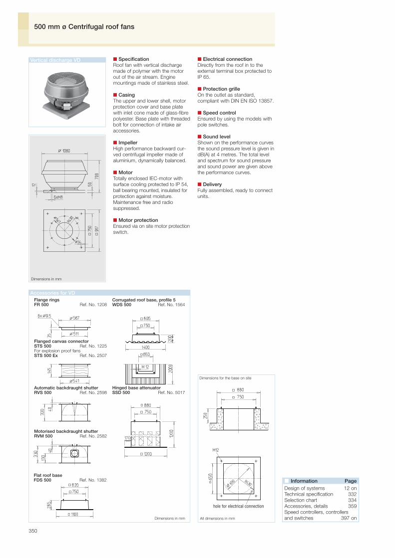
350
500 mm ø Centrifugal roof fans
Dimensions in mm
■ SpecificationRoof fan with vertical dischargemade of polymer with the motorout of the air stream. Enginemountings made of stainless steel.
■ CasingThe upper and lower shell, motorprotection cover and base platewith inlet cone made of glass-fibrepolyester. Base plate with threadedbolt for connection of intake airaccessories.
■ ImpellerHigh performance backward cur-ved centrifugal impeller made ofaluminium, dynamically balanced.
■ MotorTotally enclosed IEC-motor withsurface cooling protected to IP 54,ball bearing mounted, insulated forprotection against moisture.Maintenance free and radiosuppressed.
■ Motor protectionEnsured via on site motor protectionswitch.
■ Electrical connectionDirectly from the roof in to theexternal terminal box protected toIP 65.
■ Protection grilleOn the outlet as standard,compliant with DIN EN ISO 13857.
■ Speed controlEnsured by using the models withpole switches.
■ Sound levelShown on the performance curvesthe sound pressure level is given indB(A) at 4 metres. The total leveland spectrum for sound pressureand sound power are given abovethe performance curves.
■ DeliveryFully assembled, ready to connectunits.
All dimensions in mm
Dimensions for the base on site
Vertical discharge VD
Flange ringsFR 500 Ref. No. 1208
Corrugated roof base, profile 5WDS 500 Ref. No. 1564
Flanged canvas connectorSTS 500 Ref. No. 1225For explosion proof fansSTS 500 Ex Ref. No. 2507
Dimensions in mm
Automatic backdraught shutterRVS 500 Ref. No. 2598
Motorised backdraught shutterRVM 500 Ref. No. 2582
Hinged base attenuatorSSD 500 Ref. No. 5017
Flat roof baseFDS 500 Ref. No. 1382
Accessories for VD
■ Information PageDesign of systems 12 on Technical specification 332 Selection chart 334Accessories, details 359 Speed controllers, controllersand switches 397 on
hole for electrical connection

351
Ro
of
fans
Frequency Hz Total 125 250 500 1k 2k 4kLPA, 4m Case breakout dB(A) 75 60 70 71 68 62 59LWA Intake dB(A) 88 78 83 85 77 78 72
VD 500/4Frequency Hz Total 125 250 500 1k 2k 4kLPA, 4m Case breakout dB(A) 65 50 60 61 57 52 47LWA Intake dB(A) 78 68 73 75 67 68 60
VD 500/6
1400 min-1
72
74
75
900 min-1
62
63
65
57
58
60
VD 500/8 and 500/16
700 min-1
4243
44
350 min-1
Frequency Hz Total 125 250 500 1k 2k 4k
700min-1 LPA, 4m Case breakout dB(A) 60 44 54 56 52 46 40LWA Intake dB(A) 73 62 67 70 61 62 53
350min-1 LPA, 4m Case breakout dB(A) 44 29 39 41 37 31 25LWA Intake dB(A) 58 47 52 55 46 47 38
Type Ref. No.V· m3/h min-1 dB(A) in 4 m kW Type Ref. No.kgA No.
Pole switchRef.No.
Type Air flow volume(FID)
R.P.M. Sound pressurelevel
Power consumption Motor full protectionunit
Nominalweight
Wiringdiagram
°C
Max. air flowtemperature
VDD 500/8/62) 5209 730 / 970 6520 / 8500 60 / 65 0.72 / 1.12 2.20 / 2.60 473 60 43.0 w/o thermal contacts PGWA 124) 5083
VDD 500/8 5203 720 6520 60 0.47 1,90 470 60 38.0 w/o thermal contacts not variable3)
VDD 500/6 5204 940 8500 65 0.96 2,09 470 60 39.0 w/o thermal contacts not variable3)
VDD 500/4 5205 1450 13600 75 3.08 5,80 498 60 51.0 w/o thermal contacts not variable
VDD 500/16/8 1) 5206 360 / 720 3140 / 6520 44 / 60 0.23 / 0.60 0.62 / 1.42 471 60 38.5 w/o thermal contacts PDA 124) 5081
VDD 500/8/41) 5208 740 / 1460 6520 / 13600 60 / 75 0.57 / 3.15 2.10 / 5.75 471 60 52.5 w/o thermal contacts PDA 124) 5081VDD 500/6/42) 5210 970 / 1440 8500 / 13600 65 / 75 1.31 / 3.36 3.05 / 5.95 473 60 52.5 w/o thermal contacts PGWA 124) 5083
VDD 500/6 Ex 5212 910 8500 65 0.950 2.60 470 40 42.0 w/o thermal contacts not variable
Single speed, three phase alternating current 400 V, 50 Hz, squirrel-cage motor, protection to IP 54
Single speed, three phase alternating current 400/690 V, 50 Hz, squirrel-cage motor, protection to IP 55
Explosion proof, temperature class T1 – T3, three phase alternating current 400 V, 50 Hz, protection to IP 54
Pole-changeable, with 2 speed motor, three phase alternating current 400 V, 50 Hz, protection to IP 55
Δpstat.Pa
V· m3/h
ρ = 1.20 kg/m3Δpstat.Pa
V· m3/h
ρ = 1.20 kg/m3Δpstat.Pa
V· m3/h
ρ = 1.20 kg/m3
1) Dahlander-winding 2) Separate winding 3) In special design supplied with speed controllable motor 4) For the flush-mounted version see the product page - switches
Centrifugal roof fans ø 500 mm

Flange ringsFR 560 Ref. No. 1209
Corrugated roof base, profile 5WDS 560 Ref. No. 1564
Flanged canvas connectorSTS 560 Ref. No. 1226For explosion proof fansSTS 560 Ex Ref. No. 2508
Automatic backdraught shutterRVS 560 Ref. No. 2599
Motorised backdraught shutterRVM 560 Ref. No. 2583
Hinged base attenuatorSSD 560 Ref. No. 5017
Flat roof baseFDS 560 Ref. No. 1382
Dim. in mm
Roof fan attenuatorHSDV 560 Ref. No. 6761only for RD..
Accessories for VD and RD
352
560 mm ø Centrifugal roof fans
Dimensions in mm Dimensions in mm
Vertical discharge VD
■ SpecificationRoof fan with vertical dischargemade of polymer with the motorout ouf the air stream. Enginemountings made of stainless steel.
■ CasingThe upper and lower shell, motorprotection cover and base platewith inlet cone made of glass-fibrepolyester. Base plate with threadedbolt for connection of intake airaccessories.
■ ImpellerHigh performance backward cur-ved centrifugal impeller made ofaluminium, dynamically balanced.
■ MotorTotally enclosed IEC-motor withsurface cooling protected to IP 54,ball bearing mounted, insulated forprotection against moisture.Maintenance free and radio sup-pressed.
■ Motor protectionEnsured via on site motorprotection switch.
■ Electrical connectionDirectly from the roof in to theexternal terminal box protected toIP 65.
■ Protection grilleOn the outlet as standard,compliant with DIN EN ISO 13857.
■ Speed controlEnsured by using the models withpole switches.
■ Sound levelShown on the performance curvesthe sound pressure level is given indB(A) at 4 metres. The total leveland spectrum for sound pressureand sound power are given abovethe performance curves.
■ DeliveryFully assembled, ready to connectunits.
Horizontal discharge RD
■ Specification Centrifugal roof fan with horizontaldischarge. Flat design with largeoverlaying rain cowl.
■ CasingBase plate (with inlet cone), raincowl and other parts made ofgalvanised steel. Base plate withthreaded bolt for connection ofintake air accessories.
■ ImpellerHigh performance backwardcurved centrifugal impeller madeof galvanised steel, dynamicallybalanced with the motor unit.
■ MotorTotally enclosed external rotormotor with ball bearings, protectedto IP 44, insulated for protectionagainst moisture. Maintenance freeand radio suppressed.
■ Motor protectionThrough built-in thermal contactswhich must be connected to themotor full protection unit. Explosion proof models are equip-ped with thermal motor protectionthrough built-in PTC thermistorwhich is connected to the trippingunit MSA. Hereby speed control isallowed where the minimum voltagemust not be less than 115 V.
■ Electrical connectionTerminal box (protection to IP 55)located beneath rain cowl as stan-dard. The explosion proof modelsare supplied with a 80 cm longconnection lead. Explosion proofterminal box is available as acces-sory (KK Ex, Ref. No. 6862).
■ Protection grilleOn the outlet as standard,compliant with DIN EN ISO 13857.
■ Speed controlAll models where a speed control-ler is shown on the table are speedcontrollable via voltage reduction.Two speed models are also availa-ble.
■ Sound levelShown on the performance curvesthe sound pressure level is given indB(A) at 4 metres. The total leveland spectrum for sound pressureand sound power are given abovethe performance curves.
■ DeliveryFully assembled, ready to connectunits.
Vertical discharge VD Horizontal discharge RD
■ Information PageDesign of systems 12 on Technical specification 332 Selection chart 334Accessories, details 359 Speed controllers, controllersand switches 397 on

353
Ro
of
fans
Frequency Hz Total 125 250 500 1k 2k 4kLPA, 4m Case breakout dB(A) 79 65 72 74 74 65 63LWA Intake dB(A) 92 83 85 88 80 81 76
VD 560/4 VD 560/6 and 560/8
1400 min-1
76
77
79
900 min-1
67
68
70
46
48
VD 560/16
RD.. n=920 / 700 min-1, 6-polig
56
57
59
60
62
700 min-1
8-polig
RD.. n=700 min-1, 8-polig
45
350 min-1
60
62
63
700 min-1
Frequency Hz Total 125 250 500 1k 2k 4k
350min-1 LPA, 4m Case breakout dB(A) 48 34 43 44 42 32 30LWA Intake dB(A) 61 52 56 58 47 48 42
Frequency Hz Total 125 250 500 1k 2k 4k
900min-1 LPA, 4m Case breakout dB(A) 70 56 64 65 64 54 51LWA Intake dB(A) 82 74 77 79 69 70 64
700min-1 LPA, 4m Case breakout dB(A) 63 49 58 59 57 47 44LWA Intake dB(A) 76 67 71 73 62 63 57
1) Dahlander-winding 2) Includes motor full protection unit 3) Includes speed control and pole switch 4) For the flush-mounted version see the product page - switches
Frequency Hz Total 125 250 500 1k 2k 4k920 min-1 LWA Intake dB(A) 80 72 74 74 72 69 70700 min-1 LWA Intake dB(A) 74 66 68 68 66 63 64
Type Ref. No.V· m3/h min-1 dB(A) in 4 m kW Type Ref. No.kgA No.
Pole switchRef.No.
Type Air flow volume(FID)
R.P.M. Sound pressurelevel
Power consumption Motor full protectionunit
Nominalweight
Wiringdiagram
°C
Max. air flowtemperature
Type Ref. No.V· m3/h min-1 dB(A) in 4 m kW Type Ref. No.kgA No.
Transformer controllerSpeed-/ Pole switch
Ref.No.
Type Air flow volume(FID)
R.P.M. Sound pressurelevel
Power consumption Motor full protectionunit
Nominalweight
Wiringdiagram
°C
Max. air flowtemperature
VDD 560/8 5214 720 11300 63 0.81 1.90 470 60 51.0 w/o thermal contacts not variable3)
VDD 560/16/81) 5216 360 / 710 5400 / 11300 48 / 63 0.29 / 0.91 0.98 / 2.30 471 60 52.5 w/o thermal contacts PDA 124) 5081. VDD 560/8/41) 5217 740 / 1470 11300 / 19100 63 / 80 1.04 / 6.07 4.15 / 10.75 471 60 81.0 w/o thermal contacts PDA 124) 5081
VDD 560/6 5215 920 13200 70 1.89 4.03 470 60 54.0 w/o thermal contacts not variable3)
VDD 560/6/42) 5218 990 / 1470 13200 / 19100 70 / 80 2.09 / 5.78 4.60 / 10.10 473 60 81.0 w/o thermal contacts PGWA 124) 5083
VDD 560/6 Ex 5220 940 13200 70 1.90 4.70 470 40 72.0 w/o thermal contacts not variable
Single speed, three phase alternating current 400 V, 50 Hz, squirrel-cage motor, protection to IP 54
Pole-changeable, with 2 speed motor, three phase alternating current 400 V, 50 Hz, protection to IP 55
Explosion proof, temperature class T1 – T3, three phase alternating current 400 V, 50 Hz, protection to IP 54
RDD 560/8 1188 700 9630 54 0.76 1.80 499 55 89.0 MD 5849 RDS 22) 1315
RDD 560/12/61) 1545 470 / 920 6450 / 12750 42 / 60 0.29 / 1.73 0.93 / 3.10 472 55 104.0 M 33) 1293 PDA 124) 5081
RDD 560/6 Ex 1192 790 11300 58 1.14 2.2 838 40 89.0 MSA 1289 TSD 3.0 1502
RDD 560/6/6 1544 700 / 900 10300 / 12500 54 / 59 0.88 / 1.30 1.70 / 2.90 520 60 87.0 M 43) 1571 RDS 42) 1316
Single speed, three phase alternating current 400 V, 50 Hz, squirrel-cage motor, protection to IP 54
Explosion proof, temperature class T1 – T3, three phase alternating current 400 V, 50 Hz, protection to IP 44
Two speed, three phase alternating current 400 V, 50 Hz, Y/▲▲-switching, protection to IP 44
Pole-changeable, with 2 speed motor, three phase alternating current 400 V, 50 Hz, protection to IP 54 Pole switch
Δpstat.Pa
V· m3/h
ρ = 1.20 kg/m3Δpstat.Pa
V· m3/h
ρ = 1.20 kg/m3 Δpstat.Pa
V· m3/h
ρ = 1.20 kg/m3
Δpstat.Pa
V· m3/h
ρ = 1.20 kg/m3Δpstat.Pa
V· m3/h
ρ = 1.20 kg/m3
1) Dahlander-winding 2) Separate winding 3) In special design supplied with speed controllable motor 4) For the flush-mounted version see the product page - switches
470 min-1
40
4138
42
44
RD.. n=470 min-1
Δpstat.Pa
V· m3/h
ρ = 1.20 kg/m3
700 min-1
6-polig
920 min-1
49
51
52
53
55
52
50
52
54
56
Frequency Hz Total 125 250 500 1k 2k 4k470 min-1 LWA Intake dB(A) 62 54 56 56 54 51 52
Frequency Hz Total 125 250 500 1k 2k 4k700 min-1 LWA Intake dB(A) 73 65 67 67 65 62 63
Centrifugal roof fans ø 560 mm

354
630 mm ø Centrifugal roof fans
Dimensions in mm
■ Specification Centrifugal roof fan with horizontaldischarge. Flat design with largeoverlaying rain cowl.
■ CasingBase plate (with inlet cone), raincowl and other parts made ofgalvanised steel. Base plate withthreaded bolt for connection ofintake air accessories.
■ ImpellerHigh performance backwardcurved centrifugal impeller madeof galvanised steel, dynamicallybalanced with the motor unit.
■ MotorTotally enclosed external rotormotor with ball bearings, protectedto IP 44, insulated for protectionagainst moisture. Maintenance freeand radio suppressed.
■ Motor protectionThrough built-in thermal contactswhich must be connected to themotor full protection unit. Explosion proof models are equip-ped with thermal motor protectionthrough built-in PTC thermistorwhich is connected to the trippingunit MSA. Hereby speed control isallowed where the minimum voltagemust not be less than 115 V.
■ Electrical connectionTerminal box (protection to IP 55)located beneath rain cowl as stan-dard. The explosion proof modelsare supplied with a 80 cm longconnection lead. Explosion proofterminal box is available as acces-sory (KK Ex, Ref. No. 6862).
■ Protection grilleOn the outlet as standard,compliant with DIN EN ISO 13857.
■ Speed controlAll models where a speed control-ler is shown on the table are speedcontrollable via voltage reduction.Two speed models are also available.
■ Sound levelShown on the performance curvesthe sound pressure level is given indB(A) at 4 metres. The total leveland spectrum for sound pressureand sound power are given abovethe performance curves.
■ DeliveryFully assembled, ready to connectunits.
All dimensions in mm
Dimensions for the base on site
Dim. in mm
Flange ringsFR 630 Ref. No. 1211
Corrugated roof base, profile 5WDS 630 Ref. No. 1564
Flanged canvas connectorSTS 630 Ref. No. 1228STS 630 Ex Ref. No. 2509
Automatic backdraught shutterRVS 630 Ref. No. 2600
Motorised backdraught shutterRVM 630 Ref. No. 2609
Hinged base attenuatorSSD 630 Ref. No. 5017
Flat roof baseFDS 630 Ref. No. 1382
Roof fan attenuatorHSDV 630 Ref. No. 6761
Horizontal discharge RD
Accessories for RD
■ Information PageDesign of systems 12 on Technical specification 332 Selection chart 334Accessories, details 359 Speed controllers, controllersand switches 397 on
hole for electrical connection
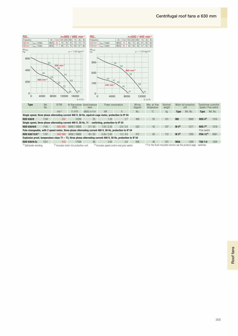
RDD 630/6 Ex 1551 910 17300 66 2.60 5.6 838 40 101 MSA 1289 TSD 7.0 1504
355
Ro
of
fans
RD.. n=880 / 680 min-1 RD.. n=650 / 440 min-1
880 min-1
59
62
61
63
65
53
56
55
57
59
650 min-1
52
53
55
55
57
4143
44
45
47
Frequency Hz Total 125 250 500 1k 2k 4k650 min-1 LWA Intake dB(A) 75 66 70 68 67 65 66440 min-1 LWA Intake dB(A) 65 56 60 58 57 55 56
Type Ref. No.V· m3/h min-1 dB(A) in 4 m kW Type Ref. No.kgA No.
Transformer controllerSpeed-/ Pole switch
Ref.No.
Type Air flow volume(FID)
R.P.M. Sound pressurelevel
Power consumption Motor full protectionunit
Nominalweight
Wiringdiagram
°C
Max. air flowtemperature
RDD 630/8 1194 650 12250 55 1.20 2.7 499 55 101 MD 5849 RDS 42) 1316
RDD 630/6/6 1195 680/ 880 13640 / 16850 57 / 63 1.50 / 2.50 2.8 / 5.0 520 45 107 M 43) 1571 RDS 72) 1578
RDD 630/12/61) 1197 440/ 880 8430 / 16850 45 / 63 0.39 / 2.60 1.5 / 4.9 472 50 112 M 33) 1293 PDA 124) 5081
Single speed, three phase alternating current 400 V, 50 Hz, squirrel-cage motor, protection to IP 54
Pole-changeable, with 2 speed motor, three phase alternating current 400 V, 50 Hz, protection to IP 54 Pole switch
Δpstat.Pa
V· m3/h
ρ = 1.20 kg/m3Δpstat.Pa
V· m3/h
ρ = 1.20 kg/m3
1) Dahlander-winding 2) Includes motor full protection unit 3) Includes speed control and pole switch 4) For the flush-mounted version see the product page - switches
680 min-1
440 min-1
Single speed, three phase alternating current 400 V, 50 Hz, Y/▲▲-switching, protection to IP 54
Frequency Hz Total 125 250 500 1k 2k 4k880 min-1 LWA Intake dB(A) 83 74 78 76 75 73 74680 min-1 LWA Intake dB(A) 77 68 72 70 69 67 68
Explosion proof, temperature class T1 – T3, three phase alternating current 400 V, 50 Hz, protection to IP 54
Centrifugal roof fans ø 630 mm

356
710 mm ø Centrifugal roof fans
Dimensions in mm
■ Specification Centrifugal roof fan with horizontaldischarge. Flat design with largeoverlaying rain cowl.
■ CasingBase plate (with inlet cone) andother parts made of galvanisedsteel. Rain cowl made of glassfibre polyester. Base plate withthreaded bolt for connection ofintake air accessories.
■ ImpellerHigh performance backwardcurved centrifugal impeller madeof galvanised steel, dynamicallybalanced with the motor unit.
■ MotorTotally enclosed external rotormotor with ball bearings, protectedto IP 44, insulated for protectionagainst moisture. Maintenance freeand radio suppressed.
■ Motor protectionAll models have built-in thermalcontacts which must be con-nected to the motor full protectionunit (see model chart) in order toprotect the motor effectively.
■ Electrical connectionTerminal box (protection to IP 55)located beneath rain cowl asstandard.
■ Protection grilleOn the outlet as standard,compliant with DIN EN ISO 13857.
■ Speed controlEnsured by using the models withpole switches.
■ Sound levelShown on the performance curvesthe sound pressure level is given indB(A) at 4 metres. The total leveland spectrum for sound pressureand sound power are given abovethe performance curves.
■ DeliveryFully assembled, ready to connectunits.
All dimensions in mm
Dimensions for the base on site
Dimensions in mm
Flange ringsFR 710 Ref. No. 1212
Hinged base attenuatorSSD 710 Ref. No. 5287
Flanged canvas connectorSTS 710 Ref. No. 1229
Automatic backdraught shutterRVS 710 Ref. No. 2601
Motorised backdraught shutterRVM 710 Ref. No. 2610
Roof fan attenuatorHSDV 710 Ref. No. 6763
Flat roof baseFDS 710 Ref. No. 6658
Accessories for RD
Horizontal discharge RD
■ Information PageDesign of systems 12 on Technical specification 332 Selection chart 334Accessories, details 359 Speed controllers, controllersand switches 397 on
hole for electrical connection

950 min-1
65
66
68
50 4747
50
52
68
70
RD 710/12/6 n=950 / 480 min-1
Δpstat.Pa
V· m3/h
ρ = 1.20 kg/m3
480 min-1
357
Ro
of
fans
Type Ref. No.V· m3/h min-1 dB(A) in 4 m kW Type Ref. No.kgA No.
Pole switchRef.No.
Type Air flow volume(FID)
R.P.M. Sound pressurelevel
Power consumption Motor full protectionunit
Nominalweight
Wiringdiagram
°C
Max. air flowtemperature
RDD 710/8 1554 660 17600 59 2.00 4.4 469 40 158 MD 5849 RDS 72) 1578RDD 710/6 1553 940 34550 72 8.60 15.8 499 40 190 MD 5849 not variable
RDD 710/12/61) 1556 480 / 950 12470 / 24800 50 / 68 0.70 / 4.50 2.4 / 8.5 472 55 167 M 33) 1293 PDA 124) 5081
Single speed, three phase alternating current 400 V, 50 Hz, squirrel-cage motor, protection to IP 54
Pole-changeable, with 2 speed motor, three phase alternating current 400 V, 50 Hz, protection to IP 54
RD 710/8 n=660 min-1
660 min-1
56
59
57
59
61
Δpstat.Pa ρ = 1.20 kg/m3
1) Dahlander-winding 2) Includes motor full protection unit 3) Includes speed control and pole switch 4) For the flush-mounted version see the product page - switches
RD 710/6 n=940 min-1
68
71
70
72
74
Δpstat.Pa
V· m3/h
ρ = 1.20 kg/m3
940 min-1
V· m3/h
Frequency Hz Total 125 250 500 1k 2k 4k950 min-1 LWA Intake dB(A) 88 79 83 81 80 78 79480 min-1 LWA Intake dB(A) 70 61 65 63 62 60 61
Frequency Hz Total 125 250 500 1k 2k 4k940 min-1 LWA Intake dB(A) 92 83 87 85 84 82 83
Frequency Hz Total 125 250 500 1k 2k 4k660 min-1 LWA Intake dB(A) 79 70 74 72 71 69 70
Centrifugal roof fans ø 710 mm

710 1276 1050 1580 751 14 670 810 15 8 x M10 65
358
Roof cowlsRoof fan attenuator for RD
560 945 750 1295 605 14 461 590 15 8 x M10 40
Dimensions in mm
Roof cowls HDH
■ SpecificationFor covering the convection andsupply air vents on the roof. Samedesign as horizontal discharge rooffans VD.. and provides uniformityof appearance for systems withsupply and extract.
When using in mechanical ventil-ation systems the emerging sys-tem losses must be considered(see diagram). Accessories as inroof fans.
Roof cowls VDH
■ SpecificationFor covering the convection andsupply air vents on the roof. Samedesign as vertical discharge rooffans VD.. and provides uniformityof appearance for systems withsupply and extract.When using in mechanical ventilati-on systems the emerging systemlosses must be considered (seediagram). Accessories as in rooffans.
HDH pres. drop – sup. airρ = 1.20 kg/m3Pressure drop VDH 200 – 400
ρ = 1.20 kg/m3Pressure drop VDH 450 und 500
ρ = 1.20 kg/m3
Type Ref. No. Nominal size in mm
HDH 315 5128 315HDH 400 5129 400HDH 450 5130 450HDH 560 5132 560HDH 630 5133 630
Type Ref. No. Nominal size in mm
VDH 200 5126 200VDH 225 5127 225VDH 250 5120 250VDH 315 5121 315VDH 400 5125 400VDH 450 5122 450VDH 500 5123 500 Dimensions in mm
315 603 450 846 356 12 264 369 16 8 x M8 32400 633 535 846 438 12 302 401 16 6 x M8 32450 754 590 1020 487 14 358 450 16 6 x M8 32
630 945 750 1295 674 14 461 635 15 8 x M10 40
Type ■■ A ■■ B ø C ø E ø F G H J K L
mm mm mm mm mm mm mm mm mm mm200 435 330 544 259 12 173 449 12 6 x M6 40225 435 330 629 259 12 173 425 12 6 x M6 40250 560 450 695 286 12 218 488 11 6 x M6 40315 560 450 770 356 12 227 535 19 8 x M8 40400 644 535 900 438 12 287 615 19 8 x M8 50450 710 590 1060 487 14 317 628 18 8 x M8 50500 917 750 1200 541 14 430 768 18 8 x M8 50
Type ■■ A ■■ B ø C ø E ø F G H J K L
mm mm mm mm mm mm mm mm mm mm
■ Model range■ Model range
➀ ➁ ➂ ➃ ➄ ➅ ➆
➀ VDH 200➁ VDH 225➂ VDH 250➃ VDH 315➄ VDH 400
➅ VDH 450➆ VDH 500
➀➁➂ ➃ ➄
➀ HDH 315➁ HDH 400➂ HDH 450➃ HDH 560➄ HDH 630➅ HDH 710
ΔpPa
ΔpPa
ΔpPa
V· m3/h
HDH pres. drop – exh. air ρ = 1.20 kg/m3
➀➁ ➂ ➃ ➄ ➅
➀ HDH 315➁ HDH 400➂ HDH 450➃ HDH 560➄ HDH 630➅ HDH 710
ΔpPa
V· m3/hV· m3/h V· m3/h
Roof cowls VDH Roof cowls HDH
HDH 710 5231 710
➅
Type Ref. No. A in mm B in mm
HSDV 225 6757 626 711
HSDV 315 6758 836 860
HSDV 400 6758 836 860
HSDV 450 6760 1016 1060
HSDV 560 6761 1256 1165
HSDV 630 6761 1256 1165
HSDV 710 6763 1556 1655
Roof fan attenuator HSDV fornoise attenuation on dischargeAverage attenuation value 11 dB.Available for models RD, nominalsizes 225 – 710.The construction encloses the rooffan and can be subsequentlymounted without any structuralalterations. Can only be mountedon RD.. models.
HSDV Dim. in mm ■ Model range

359
Ro
of
fans
Type Ref. No. ø D i.L. L A ø LK Weight in kg
DVS 180 1247 180 110 15 213 1.2
DRVS 200 2591 225 300 – 259 3.0
RVS 225 2591 225 300 – 259 3.0
RVS 250 2592 250 300 – 286 3.4
RVS 315 2594 315 300 – 356 4.3
RVS 400 2596 400 330 – 438 7,2
RVS 450 2597 454 330 15 487 10.4
RVS 500 2598 504 330 40 541 11.7
RVS 560 2599 560 330 65 605 16.1
RVS 630 2600 630 400 115 674 19.5
RVS 710 2601 710 400 155 751 26.5
Automatic backdraught shutterwith spring reverse RVS 1)
To prevent cold air backdraughtwhen the fan is not in use. Forvertical air flow bottom-up position(otherwise model RVM to be used).Auto matic opening function whenthe fan is in use. Spring mecha-nism outside the airflow. Holdingforce adjustable to fan power and
RVS / DVS
installation position. Flaps andasing made of galvanised steel,flaps with nominal sizes 225-560mm made of aluminium. Can bescrewed directly on the fan’s baseplate. With flange holes on both si-des according to DIN 24155, Pt. 2.Ambient temperature –30 to +100 °C
RVM / DRVMDimensions in mm Dimensions in mm
Type Ref. No. ø D i.L. B C L A ø LK Weight in kg
DRVM 200 2575 225 95 130 300 – 259 3.3
RVM 225 2575 225 95 130 300 – 259 3.3
RVM 250 2576 250 95 130 300 – 286 3.7
RVM 315 2578 315 95 130 300 – 356 4.6
RVM 400 2580 400 95 130 330 – 438 7.5
RVM 450 2581 454 95 130 330 15 487 10.7
RVM 500 2582 504 95 130 330 40 541 12,0
RVM 560 2583 560 95 130 330 65 605 16.4
RVM 630 2609 630 150 225 400 115 674 21.0
RVM 710 2610 710 150 225 400 155 751 28.0
Motorised backdraught shutterRVM 1) 2)
As RVS, but with spring reversingmotor, mounted outside the airflow and for vertical air flow in anydirection. Allows natural ventilationwhen the fan is not in use. Controlof air flow in combination with aroof cowl. To be electrically opera-ted together with the fan.
Connect with a 0,9 m long lead.Ambient temperature –30 to +60 °CProtection to IP 54Voltage/Frequency 230 V AC, 50/60 HzPower consumption– to Ø 560 / from Ø 630 14 W/8,5 WValve opening time, ca.– to Ø 560 / from Ø 630 75 sec./150 sec.Wiring diagram-No. SS-380.1
Flange rings FRMade of galvanised steel, for intakeduct connections. Can be screweddirectly on the fan base plate.
Dimensions in mmFR / DFR
Type Ref. No. ø LK l ø d Weight in kg
FR 180 1200 213 25 186 0.4
DFR 200 1201 259 30 233 0.5
FR 225 1201 259 30 233 0,5
FR 250 1203 286 25 256 0.6
FR 315 1204 356 30 326 0.9
FR 400 1206 438 30 408 1.2
FR 450 1207 487 35 457 1.8
FR 500 1208 541 35 511 1.8
FR 560 1209 605 35 574 2.0
FR 630 1211 674 35 642 2.2
FR 710 1212 751 35 715 3.3
Flanged canvas connector STSTo reduce vibration transmission inintake air ducting. Flanges made ofgalvanised steel. Flexible sleevemade of a polymer fabric cloth.For explosion proof fans, model
Dimensions in mmSTS / DSTS
Type Ref. No. Type * Ref. No. ø D i.L. ø LK Weight in kg
STS 180 1217 – – 183 213 0.9
DSTS 200 1218 DSTS 200 Ex 2500 229 259 1.1
STS 225 1218 STS 225 Ex 2500 229 259 1.1
STS 250 1220 STS 250 Ex 2501 252 286 1.3
STS 315 1221 STS 315 Ex 2503 322 356 1.8
STS 400 1223 STS 400 Ex 2505 404 438 2.5
STS 450 1224 STS 450 Ex 2506 453 487 3.8
STS 500 1225 STS 500 Ex 2507 507 541 3.4
STS 560 1226 STS 560 Ex 2508 570 605 4.5
STS 630 1228 STS 630 Ex 2509 638 674 4.6
STS 710 1229 – – 711 751 7.0
STS.. Ex must be used. To bemounted directly on the fan baseplate. Flange dimensions accordingto DIN 24155, Pt. 2.
*
* Model STS 180 = 130 mm
* for explosion proof fans
Dimensions according toDIN 24155, Pt. 2.
1) For pressure drop diagram see page 364. 2) DRVM../RVM.. are not suitable for explosion proof areas.
Installation accessoriesfor roof fans

360
Installation accessoriesfor roof fans
FDS SSDDimensions in mm
Type Ref. No. A in mm B in mm C in mm D in mm
FDS 180 * 1377 645 285 245 285
FDS 200 * 1378 750 392 330 285
FDS 225 * 1378 750 392 330 285
FDS 250 * 1379 870 520 450 285
FDS 315 * 1379 870 520 450 285
FDS 400 * 1380 950 605 535 285
FDS 450 * 1381 1000 660 590 285
FDS 500 1382 1160 820 750 285
FDS 560 1382 1160 820 750 285
FDS 630 1382 1160 820 750 285
FDS 710 6658 1550 1190 1050 285
Type Ref. No. A B C D E F G
WDS 180 1559 920 1600 200 245 295 ø 256 M 6
WDS 200 /225 1560 920 1600 200 330 395 290 M 10
WDS 250/315 1561 920 1600 200 450 555 395 M 10
WDS 400 1562 920 1600 200 535 625 475 M 10
WDS 450 1563 1400 2000 200 590 705 525 M 12
WDS 500/560 1564 1400 2000 200 750 895 650 M 12
WDS 630 1564 1400 2000 200 750 895 650 M 12
Dimensions in mm
Type Ref. No. A B C D E F
SSD 180 * 5289 280 160 750 213 600 245
SSD 200 * 5290 400 133 735 259 666 330
SSD 225 * 5290 400 133 735 259 666 330
SSD 250 * 5292 520 150 835 286 820 450
SSD 315 * 5292 520 150 835 356 820 450
SSD 400 * 5291 600 150 985 438 900 535
SSD 450 * 5288 675 158 985 487 990 590
SSD 500 5017 860 170 1200 – 1200 750
SSD 560 5017 860 170 1200 – 1200 750
SSD 630 5017 860 170 1200 – 1200 750
SSD 710 5287 1220 140 1500 – 1500 1050
Flat roof base FDSFor roof fans and roof cowls on flatroofs. Horizontal installation. Slopeof up to 25° is allowed with RD..roof fans. Offering re duced costand installation time compared tocrafted designs. Made of corro sionresistant glass reinforced polyesterresin (size 710 made of galvanisedsteel) with abrasion proof, soundand heat absorbing insulation. Provides a raised height off the roofgood for areas of high snow fall.
Installation To be installed above the ceilingopening (roof). Roof coating to becovered completely with felt andto be sealed with tar. Includesmounting screws, profile rubberand sealing between base andbase plate.
Hinged base attenuator SSD forintake attenuationAverage attenuation is 15 dB. Allmetal parts made of galvanisedsteel. For installation on flat roofsused like a flat roof base. Deliveryincludes mounting screws, profilerubber and sealing between baseand base plate. NG 500 – 710:Acoustically lined with nonflamma-ble material, class A2, covered onboth sides with glass fibre.
NG 180 – 450: Equipped withhinges to fold the fan for mainten-ance purposes. Foamed materialwith free cross-section allows ac-cess to ducting or shaft system.Base plate is equipped with threa-ded holes (to DIN 24155, Bl. 2) toinstall the supply air accessories.
WDS
Corrugated roof base WDSFor roof fans and roof cowls oncorrugated roof. Slope to 25°allowed with RD.. roof fans. Madeof weather proof and corrosionresistant glass reinforced polyesterresin, low on weight, low risk ofbreakage on shipment and on site. Low heat transfer. Profile distance177mm (profile No. 5). Reducescosts and installation efforts tominimum, Rain drains on the front
and rear valley between the squarebase and the corrugated plateensure an installation of roof slabindependent of the ceiling direction.Includes screws, washers andprofile rubber for mounting andsealing of the fan base plate.
* With folding mechanism for easy access and cleaning. * With folding mechanism for easy access and cleaning.
hingedhinged
Dim. in mm
Sloping roof base SDSFor roof fans and roof cowls onsloping roofs with a slope up to45°. Made of galvanised steel,with sound and thermal insulation, 50 mm thick lining inner side.
All SDS models are available onrequest. When ordering pleasespecify the fan type or the nominalsize of roof cowl, the roof pitchangle, the type of brick or theprofile shape and height (for profileroofs), if necessary.
SDS InstallationTo be installed on the roofconstruction. The enclosing collarmade of lead to be sealed.Includes mounting screws, platesand sealing between base andbase plate.
■ Note PageAll centrifugal roof fans deliveredwithout guard on intake.If there is no duct connected directly to the unit, a guard (model ASD-SGD or SG) mustbe used.
171
■ Other accessories PageSpeed controllers, controllersand switches 397 on.


![VDR G4[e] S-VDR G4[e] - Becombecom.com.sg/wp-content/uploads/2016/08/Interschalt_VDR... · 2016-08-18 · VDR G4[e] VDR Requirements S-VDR G4[e] S-VDR Requirements Overview VDR systems](https://static.fdocuments.us/doc/165x107/5f0fd2377e708231d4460c59/vdr-g4e-s-vdr-g4e-2016-08-18-vdr-g4e-vdr-requirements-s-vdr-g4e-s-vdr.jpg)