RollMaster™ 5000 Product Manual - images-na.ssl … · 1700 Jasper St., Unit F, Aurora, CO 80011...
14
1700 Jasper St., Unit F, Aurora, CO 80011 T 800.624.6706 F 303.364.7796 • Newstripe.com RollMaster™ 5000 Manual / 3068.1116 RollMaster™ 5000 Product Manual
-
Upload
dinhnguyet -
Category
Documents
-
view
213 -
download
0
Transcript of RollMaster™ 5000 Product Manual - images-na.ssl … · 1700 Jasper St., Unit F, Aurora, CO 80011...

1700 Jasper St., Unit F, Aurora, CO 80011 T 800.624.6706 F 303.364.7796 • Newstripe.com
RollMaster™ 5000 Manual / 3068.1116
RollMaster™ 5000 Product Manual

RollMaster™ 5000
ALWAYS wear safety goggles or protective eye-wear when operating the unit!
1700 Jasper St., Unit F, Aurora, CO 80011 T 800.624.6706 F 303.364.7796 • Newstripe.com
RollMaster™ 5000 Manual / 3068.1116
TABLE OF CONTENTS Precautionary Warning …………….Page 1 Required Items………………………….Page 2 Assembly ………………………………….Page 3-5 Operating Instructions………........Page 6 Cleaning Procedure…………………..Page 7 Operational Notes...………………….Page 7 Helpful Tips ...……………………………Page 8 Troubleshooting Guide……..………Page 8 Parts List……………………………………Page 9 Parts Images……………………………..Page 10 Warranty…………………………………..Page 12
Thank you! For your purchase of the Newstripe RollMaster™ 5000 Striper.
Please read over the instructions and make sure you understand operating procedures before using the unit. Please check the serial number on your unit. This Manual is for units with serial number 1015834 and above only. For units with serial numbers below 1015834, please contact Newstripe for the correct manual
RollMaster™ 5000
ALWAYS wear safety goggles or protective eye-wear when operating the unit!
1700 Jasper St., Unit F, Aurora, CO 80011 T 800.624.6706 F 303.364.7796 • Newstripe.com
RollMaster™ 5000 Manual / 3068.1116 Page 1
.
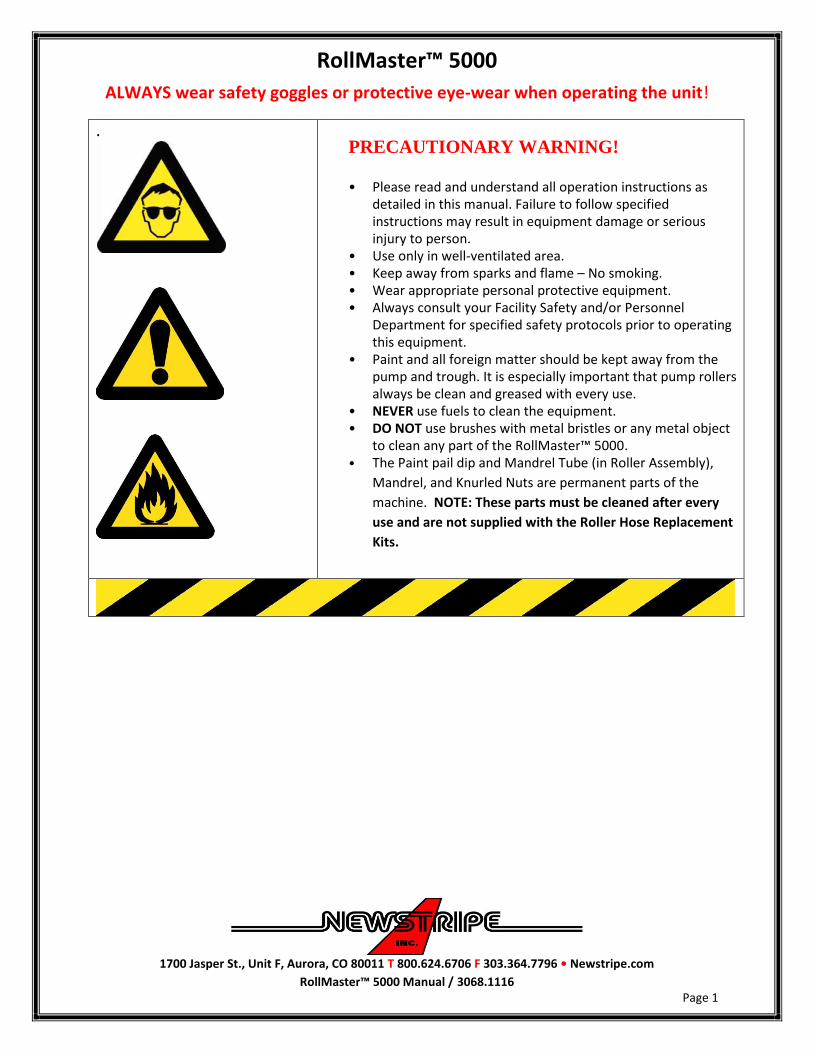
PRECAUTIONARY WARNING!
• Please read and understand all operation instructions as
detailed in this manual. Failure to follow specified instructions may result in equipment damage or serious injury to person.
• Use only in well-ventilated area. • Keep away from sparks and flame – No smoking. • Wear appropriate personal protective equipment. • Always consult your Facility Safety and/or Personnel
Department for specified safety protocols prior to operating this equipment.
• Paint and all foreign matter should be kept away from the pump and trough. It is especially important that pump rollers always be clean and greased with every use.
• NEVER use fuels to clean the equipment. • DO NOT use brushes with metal bristles or any metal object
to clean any part of the RollMaster™ 5000. • The Paint pail dip and Mandrel Tube (in Roller Assembly),
Mandrel, and Knurled Nuts are permanent parts of the
machine. NOTE: These parts must be cleaned after every
use and are not supplied with the Roller Hose Replacement
Kits.

RollMaster™ 5000
ALWAYS wear safety goggles or protective eye-wear when operating the unit!
1700 Jasper St., Unit F, Aurora, CO 80011 T 800.624.6706 F 303.364.7796 • Newstripe.com
RollMaster™ 5000 Manual / 3068.1116 Page 2
Required Items and Tools (Not Included): You will need to purchase one 18ah SLA, motorcycle battery 6 7/8” X 3 1/2” X 6 1/8”. This may be purchased at most major discount stores or auto parts dealers.
2- 1/2” wrenches 2- 7/16” wrenches 1-3/4” wrench, or two adjustable crescent wrenches 1- #2 Phillips screwdriver
Your RollMaster™ 5000 box should include
Chassis assembly with roller carrier support bar
Handle assembly with lifting rod 5-gallon pail with cover
Inside Your Pail:
Pail Dip Tube 4" Roller Kit with paint hose, Roller cover,
asphalt & concrete discs Hose guide Owner’s manual & warranty card
Parts Boxes containing:
Roller carrier Mandrel with Mandrel Nuts and Mandrel
Tube
BATTERY CROSS REFERENCE PART# Interstate P/N FAYTX20H Autozone P/N ETX20L O’Reilly Auto Parts P/N ETX20L NAPA Auto Parts P/N PSB ETX20L PowerSonic P/N PTX20-BS
Pic 1

RollMaster™ 5000
ALWAYS wear safety goggles or protective eye-wear when operating the unit!
1700 Jasper St., Unit F, Aurora, CO 80011 T 800.624.6706 F 303.364.7796 • Newstripe.com
RollMaster™ 5000 Manual / 3068.1116 Page 3
ASSEMBLY
1. Unpack the RollMaster™ 5000 chassis assembly, roller carrier, handles, pail and parts bags. The major components are held together with ¼” diameter bolts in ¾” length, and 5/16” diameter bolts in 1-1/2” lengths with locking nuts and washers. 2. Place the wheels of the chassis on a flat surface. Lay the handle assembly behind the unit (pail holder side) with the grips pointing down and the bottom of the handles towards the unit. 3. Mount bottom end of handle assembly on chassis (handles fit on outside of frame) with 5/16" x 1-1/2" bolts with washers from the inside out through the mounting holes in chassis and handles with locking nuts on the outside. (There are no washers on the outside) Do not tighten completely. 4. Swing handles into position. Align upper holes in handle support braces (braces on the outside of handles) with holes in handle and insert 5/16” x 1-1/2” long carriage bolts in holes from the outside. Tighten with locking nuts on the inside. Now tighten all of the above handle-mounting bolts. Route the trigger wiring harness between the rear axle and chassis towards the battery cover. Push the ends of the harness up through the grommet in the chassis into the battery area. 5. Remove four (4) bolts & washers securing battery cover. Slide cover upwards and set aside. 6. Remove the two wing nuts that secure the battery hold down plate. Remove the plate. Slide a new battery on the chassis between the battery hold down bolts and position the battery with terminals to the rear of the machine. Install the battery hold down plate and secure with wing nuts Install the positive side first when installing connections. Pictures for wiring are shown in Pic 2. 7. Attach the red wire lead from the paint trigger harness and the red wire lead from the battery charger to the top of the positive terminal side of the battery. 8. Attach the black wire lead (with red tape marker) from the paint trigger harness to the bottom post of the pump motor. (Marked with a red dot) 9. Attach the two black wire leads (from the pump motor and the battery charger that are tied together) to the top of the negative terminal side of the battery.
BATTERY NOT INCULDED
Pic 2

RollMaster™ 5000
ALWAYS wear safety goggles or protective eye-wear when operating the unit!
1700 Jasper St., Unit F, Aurora, CO 80011 T 800.624.6706 F 303.364.7796 • Newstripe.com
RollMaster™ 5000 Manual / 3068.1116 Page 4
10. Activate paint trigger. The motor should rotate the roller pump in a clockwise direction as you face the machine. Please call the factory if the motor is not working at this point. NOTE: A brand new battery may require charging overnight. 11. Carefully slide battery cover back onto pump support (making sure paint trigger wires do not get snagged) and secure with the four (4) bolts and washers you previously removed. 12. Remove the roller carrier from the poly bag. Remove the rubber band securing mandrel and remove the mandrel and mandrel tube from carrier. Discard the rubber band and the set mandrel aside. 13. Attach the roller carrier to the support bar by removing the bolt and washer. Lightly grease the bolt and mount the roller carrier with one washer on outside of the carrier and bolt. (Bolt should be tight enough to remove any play, but loose enough to allow the roller carrier to pivot up and down freely with both wheels sitting flat on the pavement when in the down position.) 14. Pull lifting lever backward (Operating position). Attach the lifting rod to the roller carrier by removing cotter hairpin, lightly grease the rod end and slide the rod end into hole. Re-install the cotter hairpin. (Move the lifting lever forward or back to align rod & hole) Lifting lever will now lift the carrier up off of the ground when the lever is pushed forward. 15. Install the hose guide (‘L’ shaped bar) in the hole in the front right corner of the frame so it is parallel to the front of the machine.

RollMaster™ 5000
ALWAYS wear safety goggles or protective eye-wear when operating the unit!
1700 Jasper St., Unit F, Aurora, CO 80011 T 800.624.6706 F 303.364.7796 • Newstripe.com
RollMaster™ 5000 Manual / 3068.1116 Page 5
ASSEMBLING ROLLER AND MANDREL ASSEMBLY 1. To assemble mandrel, (for the 4" roller only) install one of the plastics discs on either end of the mandrel core, over the threaded area. (Choose Asphalt or Concrete discs as needed, do not interchange. Note: Discs have a plastic film cover, peel this off before installing). Now, screw on a large round knurled nut, tight against the plastic disc (finger tight is enough). Note: The discs ride on the pavement or floor and help regulate the amount of paint the roller applies. Asphalt discs allow more paint to be applied. Concrete discs allow less paint to be applied. 2. From the opposite side of the mandrel core, slip on the 4" roller. Install the other plastic disc over the threaded area and against the roller. Screw the other knurled nut on against the disc. PLEASE NOTE: PVC spacers will be included with your kit if you ordered 2" or 3" wide rollers. Follow the above assembly instructions, except you must add these spacers between the plastic disc and the knurled nut (1/2" spacer for 3" roller, etc) 3. Insert the Mandrel Tube (‘L’ shaped 3/8" metal tubing which has a disc and a small rubber "O" ring on it) into the mandrel (only one side of the mandrel is open) with the "O" ring side inward. 4. Place the Mandrel & Roller assembly in the "J" Yokes. The Mandrel Tube disc will be on the inside of the "J" Yoke. The Mandrel tube will point to the inside of the roller carrier (towards the machine chassis). The Mandrel should slide up and down in the "J" Yokes freely. 5. Open trough by placing your thumb on the knurled pin and fingers on side of battery shroud and squeeze together (Trough will ‘click’ and lock open). 6. The paint hose has a ‘long’ end from the colored band and a short end. The short end goes towards the pail. Attach paint supply hose by pushing the long end over the open end of the mandrel tube. The hose should be in front of guide bar. Thread the hose through eyehook making sure it is under the pump and inside the trough.
IMPORTANT: the colored band on hose goes ABOVE the eyehook at top of trough. Close the trough by pulling OUT on black release knob on the trough (Trough should ‘snap’ shut). Check that the paint hose is under rollers and not pinched between sides of trough.
Pic 3
Pic 4
Pic 5

RollMaster™ 5000
ALWAYS wear safety goggles or protective eye-wear when operating the unit!
1700 Jasper St., Unit F, Aurora, CO 80011 T 800.624.6706 F 303.364.7796 • Newstripe.com
RollMaster™ 5000 Manual / 3068.1116 Page 6
OPERATION
PAINT Suggested paints are Latex (water base) or Alkyd (Oil base). These are typically sold under names like Traffic or Floor marking paints. A ‘standard’ traffic paint will say, “dry to the touch in 10-20 minutes and allow 2-3 hours for complete drying”). Most paints can be used without thinning. However, some will "flow" better and be easier to use if thinned. Normally, no more than 1/4 pint (1/2 cup) per gallon is required. A little experimenting will give you the perfect consistency. Thinning may also improve the appearance of the line on rough surfaces. PREPARATION The area to be striped should be swept clean of all dirt and cleaned of foreign matter (oil, etc.) with the use of strong detergent. Set a 5 gallon pail of paint on the chassis. GETTING STARTED Remove the cover of the existing paint pail and install the universal lid that came on the pail with the machine. Insert the paint tube (Long, ‘L’ shaped aluminum tube) in the hole in the pail lid. You may have to rotate the lid so that the paint hose reaches the short end of the paint tube. Attach the open end of the paint hose to the Paint tube. You are ready to begin painting. OPERATION The first step is to thoroughly saturate the roller. Push forward on the carrier lifting lever so that the roller is off the ground. Activate the paint trigger. Paint ‘dots’ should begin to appear on the roller after a minute. Lower the roller on some scrap cardboard or newspaper and roll the machine forward by continuing to operate the paint trigger until the roller is saturated. (You can also do this on existing painted lines, just be careful to stay on the line.) NOTE: Paint and the surface to be painted should be at room temperature for best results. Colder temperatures (Less than 70 degrees) tend to thicken the paint. The pumping mechanism is designed to delivery sufficient paint for a 4" line at a slow walking speed. The paint flow can be controlled by the operator by operating the paint trigger. When signs of excess paint leaving the roller begin to appear, the operator releases the paint trigger for a short period of time (called feathering). This practice will be required when you wish to stripe a 2" or 3" wide lines.

RollMaster™ 5000
ALWAYS wear safety goggles or protective eye-wear when operating the unit!
1700 Jasper St., Unit F, Aurora, CO 80011 T 800.624.6706 F 303.364.7796 • Newstripe.com
RollMaster™ 5000 Manual / 3068.1116 Page 7
CLEAN UP When you are finished striping, remove the roller applicator, tube assembly, and hose from the RollMaster™ 5000. This is done by opening the Trough as described earlier. Remove the end of the hose attached to the paint pail tube. Making sure the end of the hose is kept upright so not to drip any paint. Remove the hose from side of eyebolt and lift hose, mandrel tube and mandrel together off machine. This prevents any paint coming in contact with the pumping mechanism, which assures the owner of the RollMaster™ 5000 a clean, long lasting piece of equipment. Helpful Hint: Use a 2lb. coffee ‘can’ or similar container to place the hose & mandrel assembly in for transporting to a sink for cleanup. The mandrel, tube assemblies, and the roller then can be washed out in a solvent, paint thinner or water for future use. If you desire, the mandrel can be washed, and the hose and roller may be tossed away and a fresh, inexpensive, replacement kit can be purchased from your dealer or Newstripe.
OPERATIONAL NOTE! DO NOT Lacquer based, Two-part epoxy or FAST DRY paints.
Our definition of “Fast Dry” paints is those that are ready for traffic in 30 minutes. DO NOT over thin the paint. The Mandrel and Roller Cover should slide up and down freely in the “J” Yokes with side
clearance of not more than 1/32". Proper clearance was set at the factory, but it may be necessary to spread the side plates on the Carrier Assembly to regain this clearance.
The Mandrel and Roller Cover Roller should roll freely in the “J” Yokes. If not, lightly oil the short end of the Mandrel Tube and the “O” Ring.
Most paints can be used without thinning. However, some will "flow" better and may need to be thinned for easier use.
Cooler temperatures (50-65 degrees) will also require paint thinning. Normally, no more than 4 oz (1/2 cup) per gallon is required. Fast Dry paints are not recommended (Fast Dry paints are those that are “no pick up” in 30 minutes or less) Also, on rough surfaces thinning will improve the appearance of the line.
Paint should be at room temperature for best results. If Roller Cover becomes oversaturated with paint, release the Paint Trigger for a short period of
time and continue rolling forward to allow excess paint to transfer from Roller Cover to surface area. Squeeze the trigger again when roller cover requires additional paint. This practice, called feathering, will be required when the operator is striping a 2" or 3" line.
Releasing the trigger when you are 2-3 feet from the end of the line will allow you to finish with a clean and crisp end without puddling.

RollMaster™ 5000
ALWAYS wear safety goggles or protective eye-wear when operating the unit!
1700 Jasper St., Unit F, Aurora, CO 80011 T 800.624.6706 F 303.364.7796 • Newstripe.com
RollMaster™ 5000 Manual / 3068.1116 Page 8
HELPFUL TIPS The Roller Cover must be saturated with paint before a solid painted line will appear on the
painting surface. It is recommended that you saturate the Roller Cover as per the operation instructions.
We recommend that you use water-base traffic paints as they are easier to clean up and do not "lift" new asphalt surfaces.
Paint should be at least room temperature for proper operation. In colder climates, the flow of paint can be restricted because the paint becomes too thick. Make sure the paint is thin enough for the pump to pull the paint from the can and through the passageways of the Mandrel. If the paint is not thin enough, you will not get a solid line and the edges of your line not appear crisp.
When stopping for prolonged periods without use, cover the Mandrel and Roller Cover in plastic wrap to prevent it from drying out.
The machine works better if the operator moves at a slow constant pace for nice even edges.
Helpful Hint: Release the paint trigger 2’- 3’ from the end of the line and let the paint in the roller ‘run out’. This will give a clean end to the line and prevent dripping when the roller is raised.
TROUBLESHOOTING GUIDE
Problem REMEDY Paint not getting to
roller or too little paint getting to roller.
1. Make sure trough is closed. 2. Check paint hose for kink. If hose is kinked open Trough and
rotate hose. 3. Make sure the battery has enough charge to operate the pump
properly. 4. Check that all Pump Rollers are rotating. If not clean rollers of
debris or paint and lubricate. 5. Check to see if your paint is “Set Fast” or “Fast Dry”. These
paints are not recommended and require thinning, which may cause the paint to dry slower, or can diminish overall line quality.
Painted line is solid on one side, but “light” or skipping on the other
side.
1. Check that the Roller Cover slides up and down freely in the “J” Yokes and that the Mandrel is not binding. Adjust the “J” Yokes if needed or clean debris and paint off “J” Yokes.
2. If the Mandrel and Roller Cover is “riding up” on the Mandrel Carrier sides, grease the Mandrel Tube end and “O” ring with light oil.
Painted line has heavy ridges on edges or
excessive paint.
1. Make sure you are using the proper Regulating Discs. 2. Periodically release Paint Trigger every couple of feet during
striping to avoid the Roller Cover from becoming oversaturated.
Paint line skips across width of roller.
1. Make sure the Mandrel and Roller Cover are rolling freely. If not, grease “O” ring end of Mandrel Tube and “O” ring.
Please call us! If you have any questions during setup, painting or cleaning 1-800-624-6706

RollMaster™ 5000
ALWAYS wear safety goggles or protective eye-wear when operating the unit!
1700 Jasper St., Unit F, Aurora, CO 80011 T 800.624.6706 F 303.364.7796 • Newstripe.com
RollMaster™ 5000 Manual / 3068.1116 Page 9
REPLACEMENT PARTS LIST ITEM DESCRIPTION PART NUMBER 1 Battery Cover 10004657 2 Chassis 10004656 3 Wheels 10004705 4 Handle support braces (2 Required) 10004659 5 Handle Assembly 10003587 6 RollMaster™ 5000 Lid 10003098 7 Dip Tube, paint pail 10003590 8 Hose, paint (Package of 5) 10003661 9 Trigger harness 10004532 10 a. Paint trigger 10004530 b. Paint trigger boot 10004531 11 Carrier lifting lever 10003583 12 Carrier lifting rod with cotter hairpin 10003586 13 Roller Carrier 10004191 14 Mandrel Kit 10004642 Consists of: Mandrel 10000643 Nut, knurled mandrel(2 Required) 10000646 15 Tube assembly, Mandrel 10000648 16 ‘O’ ring 3/8” x 1/32” thick 10000027 17 Hose guide 10003588 18 Trough lock pin kit Includes 18a, 18b and 18C 10000671 18a Pin, lock 10000681 18b Spring, lock pin 10000680 18c Knob, lock pin 10000682 19 Trough 10000700 20 Eye, bolt w/nut 10000726 21 Roller Pump assembly 10003660 22 Battery Charger 10001332 23 Pump Motor 10003061 24 “J” Yokes 10004023
** NOTE: Paint Dip Tube and Mandrel Tube are not supplied with the roller hose replacement kits.**
4” Replacement Roller Kit (1 Roller cover, paint hose and 4 discs) 10003607 3” Replacement Roller Kit 10003608 2” Replacement Roller Kit 10003609 4” Replacement Roller covers only (Package of 12 covers & 24 discs) 10000728 3” Replacement Roller covers only please specify concrete or asphalt 10001461 2” Replacement Roller covers only 10000729

RollMaster™ 5000
ALWAYS wear safety goggles or protective eye-wear when operating the unit!
1700 Jasper St., Unit F, Aurora, CO 80011 T 800.624.6706 F 303.364.7796 • Newstripe.com
RollMaster™ 5000 Manual / 3068.1116 Page 10
Carrier Lifting
Lever 11
“J” Yokes 24
Roller Carrier 13
Carrier Lifting Rod
12
Dip Tube 7
Lid 6
Handle Assembly
5
Battery Charger
22
Mandrel Tube Assembly 15
Wheels 3
Handle Support Braces 4
Chassis 2
Hose Guide 17
Paint Trigger & Boot 10a, 10b
Battery Cover 1
Trough Lock Pin Kit 18
Roller Pump
21
Trough 19
Eye Bolt 20
Paint Hose 8
Trigger Harness 9 “O” Ring 16 Tube
Assembly 15
Mandrel Kit 14
Pump Motor23
Pic 7
Pic 6
Pic 8
Pic 9
Pic 10
Pic 11

RollMaster™ 5000
ALWAYS wear safety goggles or protective eye-wear when operating the unit!
1700 Jasper St., Unit F, Aurora, CO 80011 T 800.624.6706 F 303.364.7796 • Newstripe.com
RollMaster™ 5000 Manual / 3068.1116 Page 11
THE NEWSTRIPE WARRANTY – 18 MONTH NEWSTRIPE, INC., WARRANTS TO THE ORIGINAL PURCHASER, FOR 18 (EIGHTEEN) MONTHS AFTER DATE OF PURCHASE, THAT THE EQUIPMENT* HEREBY SOLD SHALL BE FREE OF DEFECTS IN MATERIALS AND WORKMANSHIP. THIS WARRANTY DOES NOT EXTEND TO ANY DAMAGE OR MALFUNCTION RESULTING FROM MISUSE, NEGLECT, ACCIDENT, IMPROPER OPERATION, OR NORMAL WEAR AND TEAR. Damage incurred in shipment from Newstripe, Inc. to the customer is the total responsibility of the carrier. The CUSTOMER MUST NOTE DAMAGES on the Bill of Lading of Trucking Company or Railroad; and Newstripe, Inc. will furnish to the customer the cost or parts and labor. The customer can then bill the common carrier for the damages by placing his signature on the documents. The Newstripe, Inc. obligation under this warranty and any implied warranties is limited to replacement or repair of defective parts of its manufacture without charge for 18 (Eighteen) months from date of purchase. For service under this warranty, buyer shall ship the defective part or parts of the equipment, transportation prepaid, to Newstripe, Inc. together with a written description of any claimed defect and proof of purchase date of the materials being returned. Prior to retuning any part or machine, the CUSTOMER must obtain a Return Materials Authorization number. Call 1-800-624-6706. *Gasoline engines, compressors, pumps (including airless) and Transaxles are furnished with their respective manufacturer's warranties only. Such components are not covered by any warranty of Newstripe, Inc. Where Newstripe elects to extend manufacturers’ warranties, the warranty shall be pro-rated as to cover 100% of the cost to replace or repair materials and parts for the first 12 months of ownership and 60% for the remaining 6 month period. The responsibilities described above are the only responsibilities of Newstripe, Inc. under this written warranty or any implied warranty, and may be exercised only within 18 (Eighteen) months from the date of purchase. In no event shall Newstripe, Inc. be liable for incidental or consequential damages and no person had any authority to bind it to any representation or warranty, not be responsible for work done, materials furnished or repairs made by others without its' specific written authorization. THIS WARRANTY SHALL BE IN LIEU OF ANY AND ALL OTHER WARRANTIES, EXPRESSED OR IMPLIED, INCLUDING ANY WARRANTIES OF MERCHANTABILITY OR FITNESS FOR A PARTICULAR PURPOSE, AND THERE IS NO OTHER REPRESENTATION OR WARRANTY OF ANY KIND WITH RESPECT TO THE GOODS SOLD HEREBY EXCEPT AS SET FORTH HEREIN. IT IS EXPRESSLY AGREED THAT THIS WARRANTY SHALL BE LIMITED TO THE ADJUSTMENT, REPAIR OR REPLACEMENT OF PARTS AND THE LABOR AND SERVICES REQUIRED THEREBY. IN NO EVENT, INCLUDING ANY CLAIM FOR NEGLIGENCE, SHALL NEWSTRIPE, INC. BE LIABLE FOR INCIDENTAL OR CONSEQUENTIAL DAMAGES. Sincerely, Newstripe, Inc.
1700 Jasper St., Unit F, Aurora, CO 80011 T 800.624.6706 F 303.364.7796 • Newstripe.com
RollMaster™ 5000 Manual / 3068.1116