VLT 5000/ 5000 FLUX/ 6000 HVAC/ 8000 AQUA PROFIBUS 5000 FLUX- 6000 H… · VLT® 5000/ 5000 FLUX/...
61
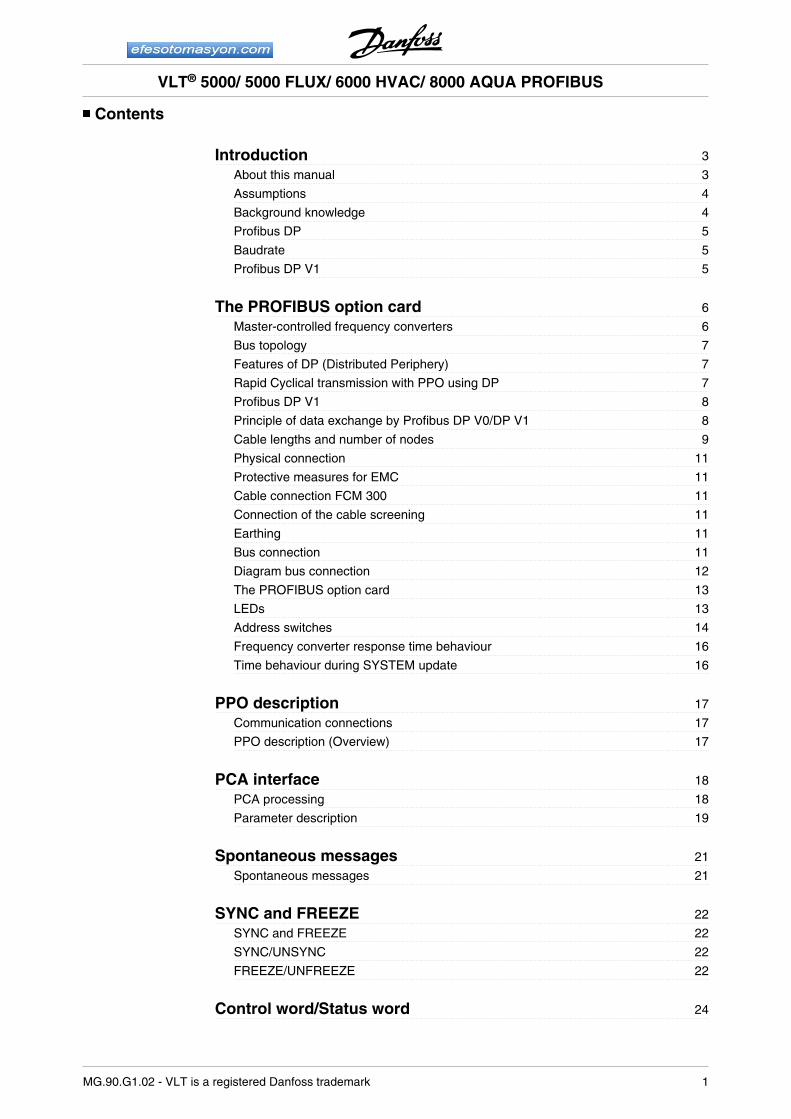
Contents Introduction 3 About this manual 3 Assumptions 4 Background knowledge 4 Profibus DP 5 Baudrate 5 Profibus DP V1 5 The PROFIBUS option card 6 Master-controlled frequency converters 6 Bus topology 7 Features of DP (Distributed Periphery) 7 Rapid Cyclical transmission with PPO using DP 7 Profibus DP V1 8 Principle of data exchange by Profibus DP V0/DP V1 8 Cable lengths and number of nodes 9 Physical connection 11 Protective measures for EMC 11 Cable connection FCM 300 11 Connection of the cable screening 11 Earthing 11 Bus connection 11 Diagram bus connection 12 The PROFIBUS option card 13 LEDs 13 Address switches 14 Frequency converter response time behaviour 16 Time behaviour during SYSTEM update 16 PPO description 17 Communication connections 17 PPO description (Overview) 17 PCA interface 18 PCA processing 18 Parameter description 19 Spontaneous messages 21 Spontaneous messages 21 SYNC and FREEZE 22 SYNC and FREEZE 22 SYNC/UNSYNC 22 FREEZE/UNFREEZE 22 Control word/Status word 24 VLT ® 5000/ 5000 FLUX/ 6000 HVAC/ 8000 AQUA PROFIBUS MG.90.G1.02 - VLT is a registered Danfoss trademark 1
Transcript of VLT 5000/ 5000 FLUX/ 6000 HVAC/ 8000 AQUA PROFIBUS 5000 FLUX- 6000 H… · VLT® 5000/ 5000 FLUX/...
Contents
Introduction 3
About this manual 3
Assumptions 4
Background knowledge 4
Profibus DP 5
Baudrate 5
Profibus DP V1 5
The PROFIBUS option card 6
Master-controlled frequency converters 6
Bus topology 7
Features of DP (Distributed Periphery) 7
Rapid Cyclical transmission with PPO using DP 7
Profibus DP V1 8
Principle of data exchange by Profibus DP V0/DP V1 8
Cable lengths and number of nodes 9
Physical connection 11
Protective measures for EMC 11
Cable connection FCM 300 11
Connection of the cable screening 11
Earthing 11
Bus connection 11
Diagram bus connection 12
The PROFIBUS option card 13
LEDs 13
Address switches 14
Frequency converter response time behaviour 16
Time behaviour during SYSTEM update 16
PPO description 17
Communication connections 17
PPO description (Overview) 17
PCA interface 18
PCA processing 18
Parameter description 19
Spontaneous messages 21
Spontaneous messages 21
SYNC and FREEZE 22
SYNC and FREEZE 22
SYNC/UNSYNC 22
FREEZE/UNFREEZE 22
Control word/Status word 24
VLT® 5000/ 5000 FLUX/ 6000 HVAC/ 8000 AQUA PROFIBUS
MG.90.G1.02 - VLT is a registered Danfoss trademark 1
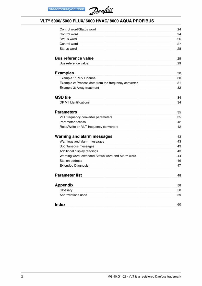
Control word/Status word 24
Control word 24
Status word 26
Control word 27
Status word 28
Bus reference value 29
Bus reference value 29
Examples 30
Example 1: PCV Channel 30
Example 2: Process data from the frequency converter 31
Example 3: Array treatment 32
GSD file 34
DP V1 Identifications 34
Parameters 35
VLT frequency converter parameters 35
Parameter access 42
Read/Write on VLT frequency converters 42
Warning and alarm messages 43
Warnings and alarm messages 43
Spontaneous messages 43
Additional display readings 43
Warning word, extended Status word and Alarm word 44
Station address 46
Extended Diagnosis 47
Parameter list 48
Appendix 58
Glossary 58
Abbreviations used 59
Index 60
VLT® 5000/ 5000 FLUX/ 6000 HVAC/ 8000 AQUA PROFIBUS
2 MG.90.G1.02 - VLT is a registered Danfoss trademark
Introduction
Copyrights, Limitation of Liability and Revision RightsThis publication contains information proprietary toDanfoss A/S. By accepting and using this manual theuser agrees that the information contained herein willbe used solely for operating equipment of Danfoss A/S or equipment from other vendors provided that suchequipment is intended for communication with Dan-foss equipment over a PROFIBUS serial communica-tion link. This publication is protected under theCopyright laws of Denmark and most other countries.
Danfoss A/S does not warrant that a software programproduced according to the guidelines provided in thismanual will function properly in every physical, hard-ware or software environment.
Although Danfoss A/S has tested and reviewed thedocumentation within this manual, Danfoss A/S makesno warranty or representation, either express or im-plied, with respect to this documentation, including itsquality, performance, or fitness for a particular pur-pose.
In no event shall Danfoss A/S be liable for direct, indi-rect, special, incidental, or consequential damagesarising out of the use, or the inability to use informationcontained in this manual, even if advised of the possi-bility of such damages. In particular, Danfoss A/S isnot responsible for any costs including but not limitedto those incurred as a result of lost profits or revenue,loss or damage of equipment, loss of computer pro-grams, loss of data, the costs to substitute these, orany claims by third parties.
Danfoss A/S reserves the right to revise this publica-tion at any time and to make changes in its contentswithout prior notice or any obligation to notify previoususers of such revisions or changes.
NB!Note regarding Profibus FMSIf you want to run FMS you have to pur-chase as follows:
For VLT 5000:
175Z3722 (uncoated)
175Z3723 (coated)
For VLT 6000 HVAC:
175Z4207 (uncoated)
175Z4208 (coated)
It is NOT possible to run FMS from a VLT5000 FLUX or a VLT 8000 AQUA.
This manual does not deal with ProfibusFMS, only with Profibus DP. However, inthe event that the communication is to bebuilt up through Profibus FMS, you shouldrequest the description MG.10.E3.yy”Profibus Product Manual“ which alsocontains a description of the Profibus FMSfunctions of the Profibus option card.
About this manual
This manual is intended as both an instruction manualand a reference guide. It only broaches the basics ofthe PROFIBUS DP protocol, and only when it is nec-essary to provide a sufficient understanding of thePROFIDRIVE implementation of the PROFIBUS pro-file for frequency converters (version 2, PNO) and ofthe PROFIBUS option card for the series VLT 5000/VLT 5000 Flux/VLT 6000 HVAC/VLT 8000 AQUA byDANFOSS.
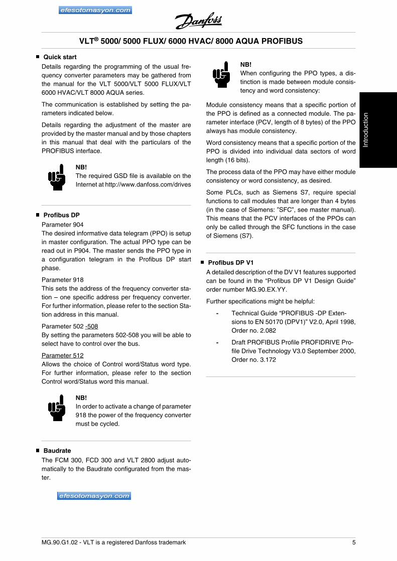
Unit Software versionFCD 300 Ver. 1.30FCM 300 -VLT 2800 Ver. 2.64VLT 5000 Ver. 3.62VLT 6000 HVAC Ver. 2.41VLT 8000 AQUA Ver. 1.12
The above table shows from which software versionsProfibus DP V1 is supported. The software version canbe read-out in parameter 624 Software versions.
This manual gives detailed information of the DP V0features supported, sufficient for most programmingand maintenance activities. The DP V1 however isbriefly described. For programming purposes the Pro-fibus DP V1 Design Guide order number MG.90.EX.YY(X is the version number, and YY the language code)might be necessary.
It is suggested that readers who are not completelyfamiliar with PROFIBUS DP or the profile for frequencyconverters review the relevant literature on these sub-jects.
Even if you are an experienced PROFIBUS program-mer, we suggest that you read this manual in its en-tirety before you start programming, since importantinformation can be found in all chapters.
The section Quick start deals with the quick start of thecommunication parameters for the DP communica-tion.
The chapter The Profibus option card contains detailsregarding the PROFIBUS option card and the estab-lishment of the physical connection.
VLT® 5000/ 5000 FLUX/ 6000 HVAC/ 8000 AQUA PROFIBUS
MG.90.G1.02 - VLT is a registered Danfoss trademark 3
Intr
oduc
tion
Please refer to section Timing for information regardingthe time behaviour.
The chapter PPO description presents an overview ofthe PPOs (informative data telegrams).
The PCA interface as a parameter interface in the PPOis explained in chapter PCA interface.
Section Parameters and data type structures containsthe description of the parameter and data structure.
Chapter Spontaneous messages contains a descrip-tion of spontaneous messages.
The response to the ”Sync” and ”Freeze” commandsis explained in chapter SYNC and FREEZE.
The Control word and Status word as essential ele-ments of the PPOs for the operational Control, as wellas the bus reference value are explained in chapterBus reference value.
Chapter Examples contains examples for the use of thePPOs. It is recommended that readers review the ex-amples for a better understanding of the PPOs.
Chapter Parameters contains the frequency converterparameters specific to the Profibus. Warning andalarm messages and display readings specific to theProfibus are described in chapter Warning and alarmmessages.
A parameter listing as an overview of all VLT 5000/VLT5000 Flux/VLT 6000 HVAC/VLT 8000 AQUA param-eters can be found in chapter Parameter list.
In chapter Appendix you will find the abbreviationsused in this manual. The manual concludes with ashort glossary and a detailed index for quick naviga-tion.
If you are interested in learning more about the PRO-FIBUS protocol in general, we recommend that youconsult the relevant, very comprehensive literature forthis purpose.
Assumptions
The manual assumes that you are using a DANFOSSPROFIBUS DP option card, together with a DANFOSSVLT frequency converter, that you are using a PLC ora PC with a serial interface as master which supportsall communication services for PROFIBUS, and thatall requirements are met and all limitations are ob-served which arise from the PROFIBUS standard, thePROFIBUS profile of frequency converters, and thecompany-specific implementation of PROFIDRIVE, orthose of the frequency converter drives.
The Profibus DP V1 is an extension of the former Pro-fibus DP V0 funcionality.
Background knowledge
The DANFOSS PROFIBUS option card is designed forthe communication with all masters that comply withthe PROFIBUS DP V0 and DP V1 standard. Thus, theassumption is made that you are familiar with the PCor PLC to be used as a master on your SYSTEM. Anyquestions regarding the hardware or software of othersuppliers are beyond the scope of this manual andoutside the responsibility of DANFOSS.
In the event of questions concerning the configurationof the master-to-master communication or the config-uration with a slave not manufactured by DANFOSS,you should refer to the information in the respectivemanuals.
VLT® 5000/ 5000 FLUX/ 6000 HVAC/ 8000 AQUA PROFIBUS
4 MG.90.G1.02 - VLT is a registered Danfoss trademark
Quick start
Details regarding the programming of the usual fre-quency converter parameters may be gathered fromthe manual for the VLT 5000/VLT 5000 FLUX/VLT6000 HVAC/VLT 8000 AQUA series.
The communication is established by setting the pa-rameters indicated below.
Details regarding the adjustment of the master areprovided by the master manual and by those chaptersin this manual that deal with the particulars of thePROFIBUS interface.
NB!The required GSD file is available on theInternet at http://www.danfoss.com/drives
Profibus DP
Parameter 904The desired informative data telegram (PPO) is setupin master configuration. The actual PPO type can beread out in P904. The master sends the PPO type ina configuration telegram in the Profibus DP startphase.
Parameter 918This sets the address of the frequency converter sta-tion – one specific address per frequency converter.For further information, please refer to the section Sta-tion address in this manual.
Parameter 502 -508By setting the parameters 502-508 you will be able toselect have to control over the bus.
Parameter 512Allows the choice of Control word/Status word type.For further information, please refer to the sectionControl word/Status word this manual.
NB!In order to activate a change of parameter918 the power of the frequency convertermust be cycled.
Baudrate
The FCM 300, FCD 300 and VLT 2800 adjust auto-matically to the Baudrate configurated from the mas-ter.
NB!When configuring the PPO types, a dis-tinction is made between module consis-tency and word consistency:
Module consistency means that a specific portion ofthe PPO is defined as a connected module. The pa-rameter interface (PCV, length of 8 bytes) of the PPOalways has module consistency.
Word consistency means that a specific portion of thePPO is divided into individual data sectors of wordlength (16 bits).
The process data of the PPO may have either moduleconsistency or word consistency, as desired.
Some PLCs, such as Siemens S7, require specialfunctions to call modules that are longer than 4 bytes(in the case of Siemens: ”SFC”, see master manual).This means that the PCV interfaces of the PPOs canonly be called through the SFC functions in the caseof Siemens (S7).
Profibus DP V1
A detailed description of the DV V1 features supportedcan be found in the “Profibus DP V1 Design Guide”order number MG.90.EX.YY.
Further specifications might be helpful:
- Technical Guide “PROFIBUS -DP Exten-sions to EN 50170 (DPV1)” V2.0, April 1998,Order no. 2.082
- Draft PROFIBUS Profile PROFIDRIVE Pro-file Drive Technology V3.0 September 2000,Order no. 3.172
VLT® 5000/ 5000 FLUX/ 6000 HVAC/ 8000 AQUA PROFIBUS
MG.90.G1.02 - VLT is a registered Danfoss trademark 5
Intr
oduc
tion
Master-controlled frequency converters
The PROFIBUS Fieldbus was designed to give youunprecedented flexibility and command over your con-trolled SYSTEM. The PROFIBUS will perform as anintegrated part of your frequency converter, giving youaccess to all parameters relevant to your application.The frequency converter will always act as a slave, andtogether with a master it can exchange a multitude ofinformation and commands. Control signals such asspeed reference, start / stop of motor, reverse opera-tion, etc. are transmitted from the master in the form ofa telegramme. The frequency converter acknowledg-es receipt by transmitting status signals, such as run-ning, on reference, motor stopped and so on to themaster. The frequency converter may also transmitfault indications, alarms and warnings to the master,such as Overcurrent or Phaseloss.
The PROFIBUS communicates in accordance with thePROFIBUS field bus standard, EN 50170, part 3. It canthus exchange data with all masters that meet thisstandard; however, this does not mean that all serv-ices available in the PROFIDRIVE profile standard aresupported. The PROFIBUS profile for frequency con-verters (version 2 and partly version 3, PNO) is a partof PROFIBUS which supports only those services thatconcern applications with speed control.
Communication partnersIn a control SYSTEM the frequency converter will al-ways act as a slave, and as such it may communicatewith a single master or multiple masters depending onthe nature of the application. A master may be a PLCor a PC that is equipped with a PROFIBUS communi-cation card.
VLT® 5000/ 5000 FLUX/ 6000 HVAC/ 8000 AQUA PROFIBUS
6 MG.90.G1.02 - VLT is a registered Danfoss trademark
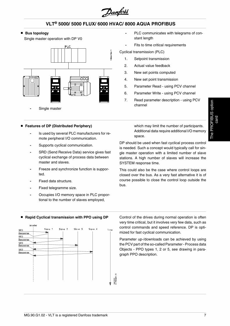
Bus topology
Single master operation with DP V0
- Single master
- PLC communicates with telegrams of con-stant length
- Fits to time critical requirements
Cyclical transmission (PLC)
1. Setpoint transmission
2. Actual value feedback
3. New set points computed
4. New set point transmission
5. Parameter Read - using PCV channel
6. Parameter Write - using PCV channel
7. Read parameter description - using PCVchannel
Features of DP (Distributed Periphery)
- Is used by several PLC manufacturers for re-mote peripheral I/O communication.
- Supports cyclical communication.
- SRD (Send Receive Data) service gives fastcyclical exchange of process data betweenmaster and slaves.
- Freeze and synchronize function is suppor-ted.
- Fixed data structure.
- Fixed telegramme size.
- Occupies I/O memory space in PLC propor-tional to the number of slaves employed,
which may limit the number of participants.Additional data require additional I/O memoryspace.
DP should be used when fast cyclical process controlis needed. Such a concept would typically call for sin-gle master operation with a limited number of slavestations. A high number of slaves will increase theSYSTEM response time.
This could also be the case where control loops areclosed over the bus. As a very fast alternative it is ofcourse possible to close the control loop outside thebus.
Rapid Cyclical transmission with PPO using DP Control of the drives during normal operation is oftenvery time critical, but it involves very few data, such ascontrol commands and speed reference. DP is opti-mized for fast cyclical communication.
Parameter up-/downloads can be achieved by usingthe PCV part of the so-called Parameter - Process dataObjects - PPO types 1, 2 or 5, see drawing in para-graph PPO description.
VLT® 5000/ 5000 FLUX/ 6000 HVAC/ 8000 AQUA PROFIBUS
MG.90.G1.02 - VLT is a registered Danfoss trademark 7
The
PR
OF
IBU
S o
ptio
nca
rd
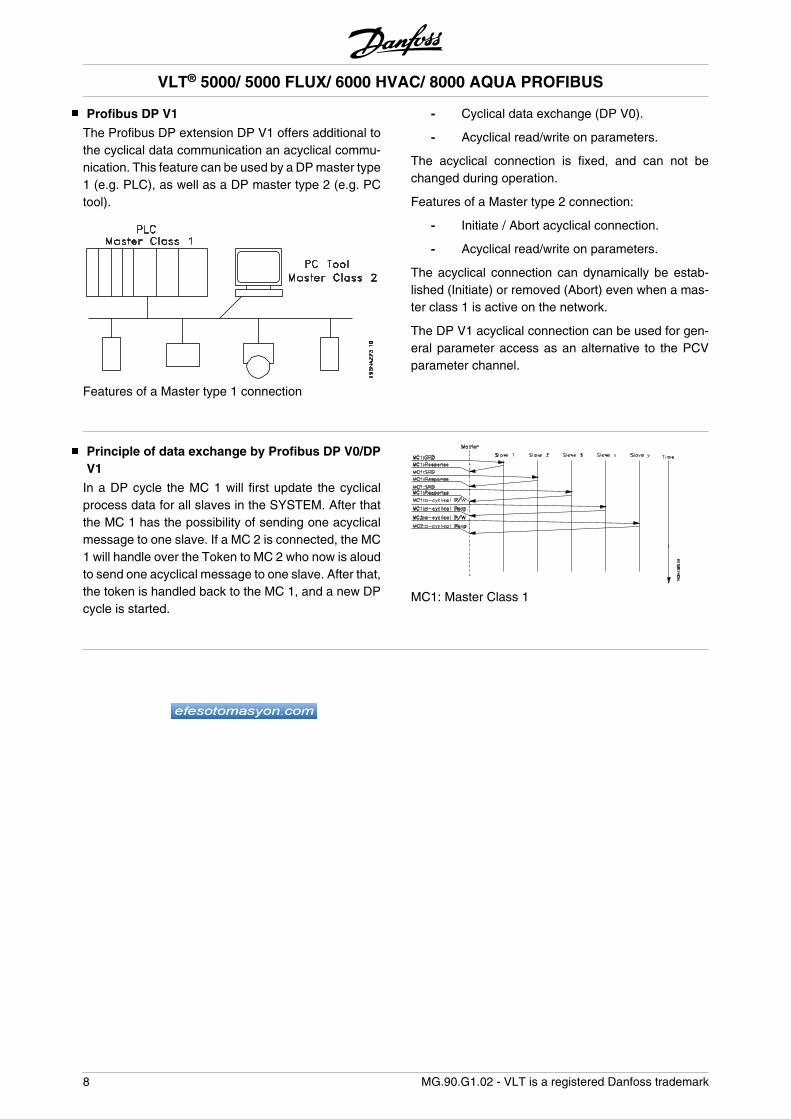
Profibus DP V1
The Profibus DP extension DP V1 offers additional tothe cyclical data communication an acyclical commu-nication. This feature can be used by a DP master type1 (e.g. PLC), as well as a DP master type 2 (e.g. PCtool).
Features of a Master type 1 connection
- Cyclical data exchange (DP V0).
- Acyclical read/write on parameters.
The acyclical connection is fixed, and can not bechanged during operation.
Features of a Master type 2 connection:
- Initiate / Abort acyclical connection.
- Acyclical read/write on parameters.
The acyclical connection can dynamically be estab-lished (Initiate) or removed (Abort) even when a mas-ter class 1 is active on the network.
The DP V1 acyclical connection can be used for gen-eral parameter access as an alternative to the PCVparameter channel.
Principle of data exchange by Profibus DP V0/DPV1
In a DP cycle the MC 1 will first update the cyclicalprocess data for all slaves in the SYSTEM. After thatthe MC 1 has the possibility of sending one acyclicalmessage to one slave. If a MC 2 is connected, the MC1 will handle over the Token to MC 2 who now is aloudto send one acyclical message to one slave. After that,the token is handled back to the MC 1, and a new DPcycle is started.
MC1: Master Class 1
VLT® 5000/ 5000 FLUX/ 6000 HVAC/ 8000 AQUA PROFIBUS
8 MG.90.G1.02 - VLT is a registered Danfoss trademark
Cable lengths and number of nodes
The maximum cable of a segment depends on thetransmission speed. The total cable length includesstub lines, if applicable. A stub line is the connectionfrom the main bus cable to each node if a ”T” connec-tion exists instead of a direct connection of the mainbus cable to the nodes; cf. the stub line length. Thefollowing table shows the maximum permitted cablelengths and the maximum or frequency converterswith 1, 2, 3 or 4 bus segments.
Please note that a repeater switched between twosegments represents a node in both segments. Thenumber of frequency converters is based on a SYS-TEM with only one master. In the case of multiple
masters, the number of frequency converters must bereduced accordingly.
The total stub line length of a segment is limited asfollows:
Stub line length Transmission speed Max. stub line length per
segment [m]9.6-93.75 kBaud 96187.5 kBaud 75500 kBaud 301.5 MBaud 103-12 MBaud none
Maximum total bus cable lengthTransmission speed 1 segment:
32 nodes (31 frequen-cy converters) [m]
2 segments:64 nodes (1 repeater,61 frequency convert-ers) [m]
3 segments:96 nodes (2 repeater,91 frequency convert-ers) [m]
4 segments:128 nodes (3 repeater,121 frequency con-verters) [m]
9.6-187.5 kBaud 1000 2000 3000 4000500 kBaud 400 800 1200 16001.5 MBaud 200 400 600 8003-12 MBaud 100 200 300 400
VLT® 5000/ 5000 FLUX/ 6000 HVAC/ 8000 AQUA PROFIBUS
MG.90.G1.02 - VLT is a registered Danfoss trademark 9
The
PR
OF
IBU
S o
ptio
nca
rd
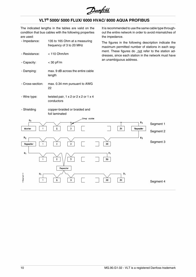
The indicated lengths in the tables are valid on thecondition that bus cables with the following propertiesare used:- Impedance: 135 to 165 Ohm at a measuring
frequency of 3 to 20 MHz - Resistance: < 110 Ohm/km - Capacity: < 30 pF/m - Damping: max. 9 dB across the entire cable
length - Cross-section: max. 0.34 mm pursuant to AWG
22 - Wire type: twisted pair, 1 x 2 or 2 x 2 or 1 x 4
conductors - Shielding copper-braided or braided and
foil laminated
It is recommended to use the same cable type through-out the entire network in order to avoid mismatches ofthe impedance.
The figures in the following description indicate themaximum permitted number of stations in each seg-ment. These figures do not refer to the station ad-dresses, since each station in the network must havean unambiguous address.
Segment 1
Segment 2
Segment 3
Segment 4
VLT® 5000/ 5000 FLUX/ 6000 HVAC/ 8000 AQUA PROFIBUS
10 MG.90.G1.02 - VLT is a registered Danfoss trademark
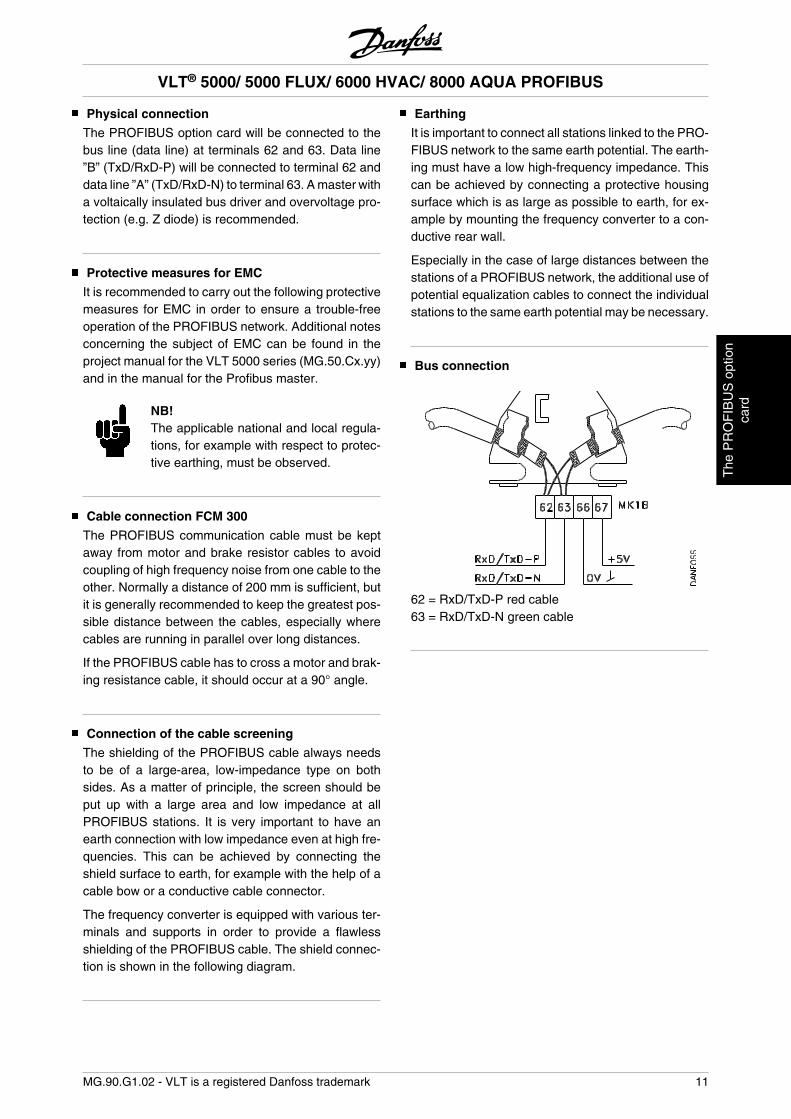
Physical connection
The PROFIBUS option card will be connected to thebus line (data line) at terminals 62 and 63. Data line”B” (TxD/RxD-P) will be connected to terminal 62 anddata line ”A” (TxD/RxD-N) to terminal 63. A master witha voltaically insulated bus driver and overvoltage pro-tection (e.g. Z diode) is recommended.
Protective measures for EMC
It is recommended to carry out the following protectivemeasures for EMC in order to ensure a trouble-freeoperation of the PROFIBUS network. Additional notesconcerning the subject of EMC can be found in theproject manual for the VLT 5000 series (MG.50.Cx.yy)and in the manual for the Profibus master.
NB!The applicable national and local regula-tions, for example with respect to protec-tive earthing, must be observed.
Cable connection FCM 300
The PROFIBUS communication cable must be keptaway from motor and brake resistor cables to avoidcoupling of high frequency noise from one cable to theother. Normally a distance of 200 mm is sufficient, butit is generally recommended to keep the greatest pos-sible distance between the cables, especially wherecables are running in parallel over long distances.
If the PROFIBUS cable has to cross a motor and brak-ing resistance cable, it should occur at a 90° angle.
Connection of the cable screening
The shielding of the PROFIBUS cable always needsto be of a large-area, low-impedance type on bothsides. As a matter of principle, the screen should beput up with a large area and low impedance at allPROFIBUS stations. It is very important to have anearth connection with low impedance even at high fre-quencies. This can be achieved by connecting theshield surface to earth, for example with the help of acable bow or a conductive cable connector.
The frequency converter is equipped with various ter-minals and supports in order to provide a flawlessshielding of the PROFIBUS cable. The shield connec-tion is shown in the following diagram.
Earthing
It is important to connect all stations linked to the PRO-FIBUS network to the same earth potential. The earth-ing must have a low high-frequency impedance. Thiscan be achieved by connecting a protective housingsurface which is as large as possible to earth, for ex-ample by mounting the frequency converter to a con-ductive rear wall.
Especially in the case of large distances between thestations of a PROFIBUS network, the additional use ofpotential equalization cables to connect the individualstations to the same earth potential may be necessary.
Bus connection
62 = RxD/TxD-P red cable63 = RxD/TxD-N green cable
VLT® 5000/ 5000 FLUX/ 6000 HVAC/ 8000 AQUA PROFIBUS
MG.90.G1.02 - VLT is a registered Danfoss trademark 11
The
PR
OF
IBU
S o
ptio
nca
rd
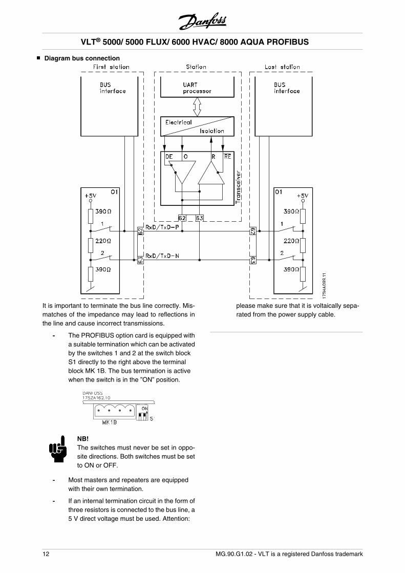
Diagram bus connection
It is important to terminate the bus line correctly. Mis-matches of the impedance may lead to reflections inthe line and cause incorrect transmissions.
- The PROFIBUS option card is equipped witha suitable termination which can be activatedby the switches 1 and 2 at the switch blockS1 directly to the right above the terminalblock MK 1B. The bus termination is activewhen the switch is in the ”ON” position.
NB!The switches must never be set in oppo-site directions. Both switches must be setto ON or OFF.
- Most masters and repeaters are equippedwith their own termination.
- If an internal termination circuit in the form ofthree resistors is connected to the bus line, a5 V direct voltage must be used. Attention:
please make sure that it is voltaically sepa-rated from the power supply cable.
VLT® 5000/ 5000 FLUX/ 6000 HVAC/ 8000 AQUA PROFIBUS
12 MG.90.G1.02 - VLT is a registered Danfoss trademark
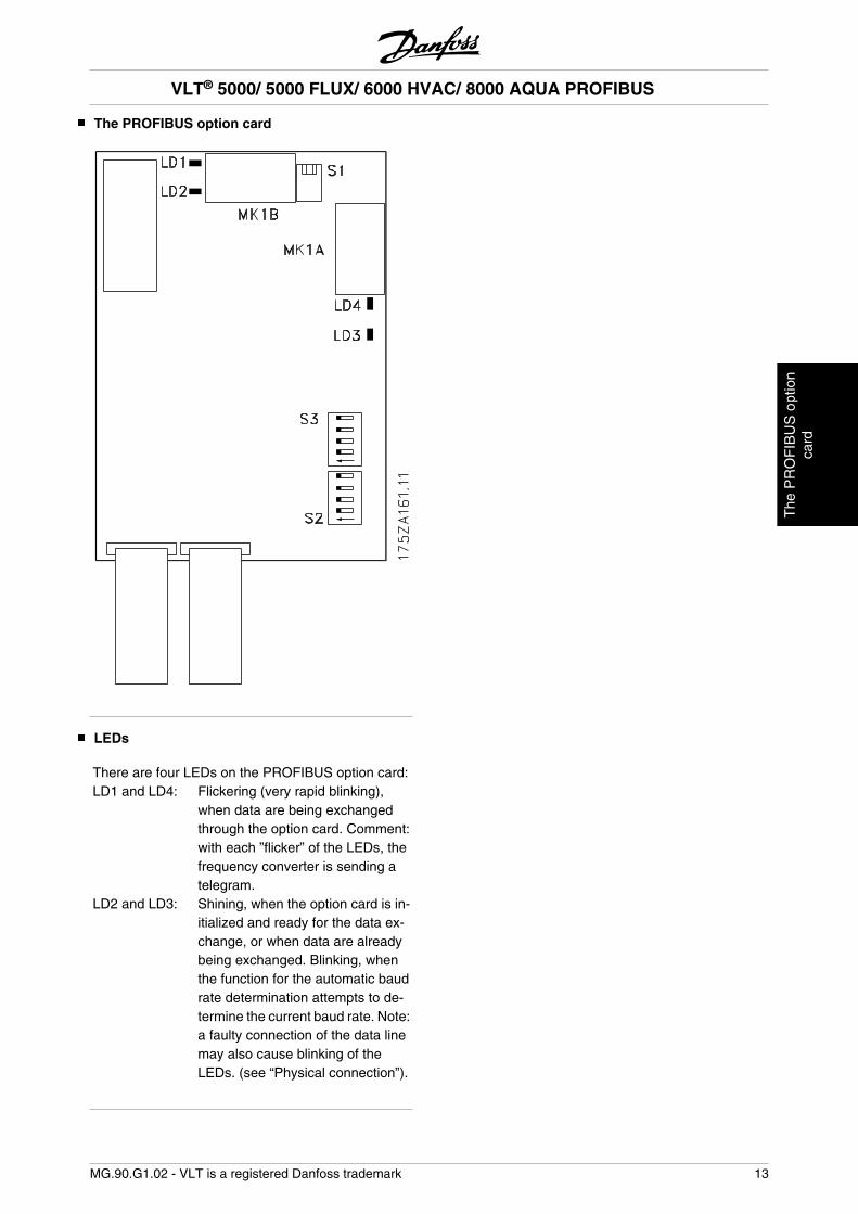
The PROFIBUS option card
LEDs
There are four LEDs on the PROFIBUS option card:LD1 and LD4: Flickering (very rapid blinking),
when data are being exchangedthrough the option card. Comment:with each ”flicker” of the LEDs, thefrequency converter is sending atelegram.
LD2 and LD3: Shining, when the option card is in-itialized and ready for the data ex-change, or when data are alreadybeing exchanged. Blinking, whenthe function for the automatic baudrate determination attempts to de-termine the current baud rate. Note:a faulty connection of the data linemay also cause blinking of theLEDs. (see “Physical connection”).
VLT® 5000/ 5000 FLUX/ 6000 HVAC/ 8000 AQUA PROFIBUS
MG.90.G1.02 - VLT is a registered Danfoss trademark 13
The
PR
OF
IBU
S o
ptio
nca
rd
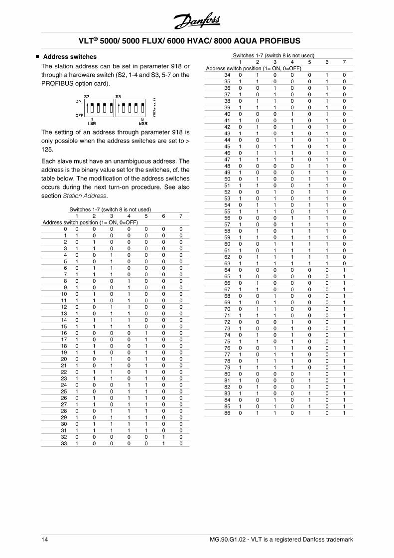
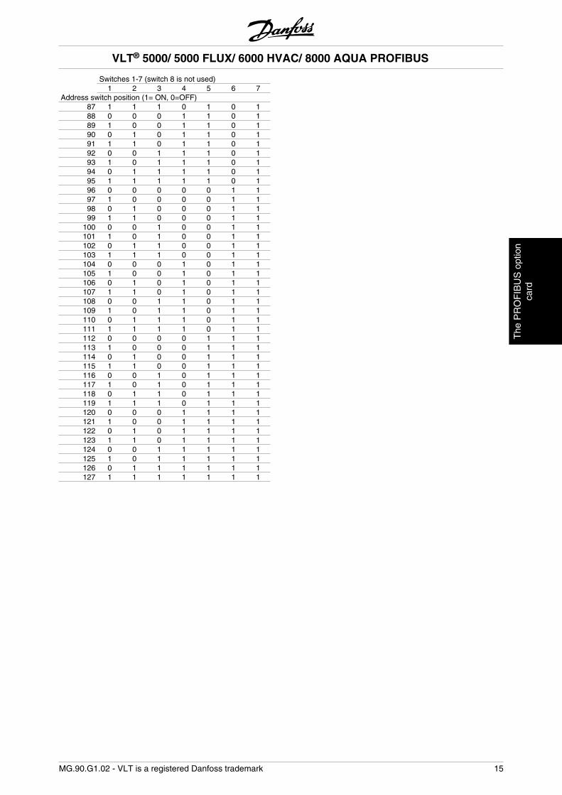
Address switches
The station address can be set in parameter 918 orthrough a hardware switch (S2, 1-4 and S3, 5-7 on thePROFIBUS option card).
The setting of an address through parameter 918 isonly possible when the address switches are set to >125.
Each slave must have an unambiguous address. Theaddress is the binary value set for the switches, cf. thetable below. The modification of the address switchesoccurs during the next turn-on procedure. See alsosection Station Address.
Switches 1-7 (switch 8 is not used) 1 2 3 4 5 6 7Address switch position (1= ON, 0=OFF)
0 0 0 0 0 0 0 01 1 0 0 0 0 0 02 0 1 0 0 0 0 03 1 1 0 0 0 0 04 0 0 1 0 0 0 05 1 0 1 0 0 0 06 0 1 1 0 0 0 07 1 1 1 0 0 0 08 0 0 0 1 0 0 09 1 0 0 1 0 0 0
10 0 1 0 1 0 0 011 1 1 0 1 0 0 012 0 0 1 1 0 0 013 1 0 1 1 0 0 014 0 1 1 1 0 0 015 1 1 1 1 0 0 016 0 0 0 0 1 0 017 1 0 0 0 1 0 018 0 1 0 0 1 0 019 1 1 0 0 1 0 020 0 0 1 0 1 0 021 1 0 1 0 1 0 022 0 1 1 0 1 0 023 1 1 1 0 1 0 024 0 0 0 1 1 0 025 1 0 0 1 1 0 026 0 1 0 1 1 0 027 1 1 0 1 1 0 028 0 0 1 1 1 0 029 1 0 1 1 1 0 030 0 1 1 1 1 0 031 1 1 1 1 1 0 032 0 0 0 0 0 1 033 1 0 0 0 0 1 0
Switches 1-7 (switch 8 is not used) 1 2 3 4 5 6 7Address switch position (1= ON, 0=OFF)
34 0 1 0 0 0 1 035 1 1 0 0 0 1 036 0 0 1 0 0 1 037 1 0 1 0 0 1 038 0 1 1 0 0 1 039 1 1 1 0 0 1 040 0 0 0 1 0 1 041 1 0 0 1 0 1 042 0 1 0 1 0 1 043 1 1 0 1 0 1 044 0 0 1 1 0 1 045 1 0 1 1 0 1 046 0 1 1 1 0 1 047 1 1 1 1 0 1 048 0 0 0 0 1 1 049 1 0 0 0 1 1 050 0 1 0 0 1 1 051 1 1 0 0 1 1 052 0 0 1 0 1 1 053 1 0 1 0 1 1 054 0 1 1 0 1 1 055 1 1 1 0 1 1 056 0 0 0 1 1 1 057 1 0 0 1 1 1 058 0 1 0 1 1 1 059 1 1 0 1 1 1 060 0 0 1 1 1 1 061 1 0 1 1 1 1 062 0 1 1 1 1 1 063 1 1 1 1 1 1 064 0 0 0 0 0 0 165 1 0 0 0 0 0 166 0 1 0 0 0 0 167 1 1 0 0 0 0 168 0 0 1 0 0 0 169 1 0 1 0 0 0 170 0 1 1 0 0 0 171 1 1 1 0 0 0 172 0 0 0 1 0 0 173 1 0 0 1 0 0 174 0 1 0 1 0 0 175 1 1 0 1 0 0 176 0 0 1 1 0 0 177 1 0 1 1 0 0 178 0 1 1 1 0 0 179 1 1 1 1 0 0 180 0 0 0 0 1 0 181 1 0 0 0 1 0 182 0 1 0 0 1 0 183 1 1 0 0 1 0 184 0 0 1 0 1 0 185 1 0 1 0 1 0 186 0 1 1 0 1 0 1
VLT® 5000/ 5000 FLUX/ 6000 HVAC/ 8000 AQUA PROFIBUS
14 MG.90.G1.02 - VLT is a registered Danfoss trademark
Switches 1-7 (switch 8 is not used) 1 2 3 4 5 6 7Address switch position (1= ON, 0=OFF)
87 1 1 1 0 1 0 188 0 0 0 1 1 0 189 1 0 0 1 1 0 190 0 1 0 1 1 0 191 1 1 0 1 1 0 192 0 0 1 1 1 0 193 1 0 1 1 1 0 194 0 1 1 1 1 0 195 1 1 1 1 1 0 196 0 0 0 0 0 1 197 1 0 0 0 0 1 198 0 1 0 0 0 1 199 1 1 0 0 0 1 1
100 0 0 1 0 0 1 1101 1 0 1 0 0 1 1102 0 1 1 0 0 1 1103 1 1 1 0 0 1 1104 0 0 0 1 0 1 1105 1 0 0 1 0 1 1106 0 1 0 1 0 1 1107 1 1 0 1 0 1 1108 0 0 1 1 0 1 1109 1 0 1 1 0 1 1110 0 1 1 1 0 1 1111 1 1 1 1 0 1 1112 0 0 0 0 1 1 1113 1 0 0 0 1 1 1114 0 1 0 0 1 1 1115 1 1 0 0 1 1 1116 0 0 1 0 1 1 1117 1 0 1 0 1 1 1118 0 1 1 0 1 1 1119 1 1 1 0 1 1 1120 0 0 0 1 1 1 1121 1 0 0 1 1 1 1122 0 1 0 1 1 1 1123 1 1 0 1 1 1 1124 0 0 1 1 1 1 1125 1 0 1 1 1 1 1126 0 1 1 1 1 1 1127 1 1 1 1 1 1 1
VLT® 5000/ 5000 FLUX/ 6000 HVAC/ 8000 AQUA PROFIBUS
MG.90.G1.02 - VLT is a registered Danfoss trademark 15
The
PR
OF
IBU
S o
ptio
nca
rd
Timing
Frequency converter response time behaviour
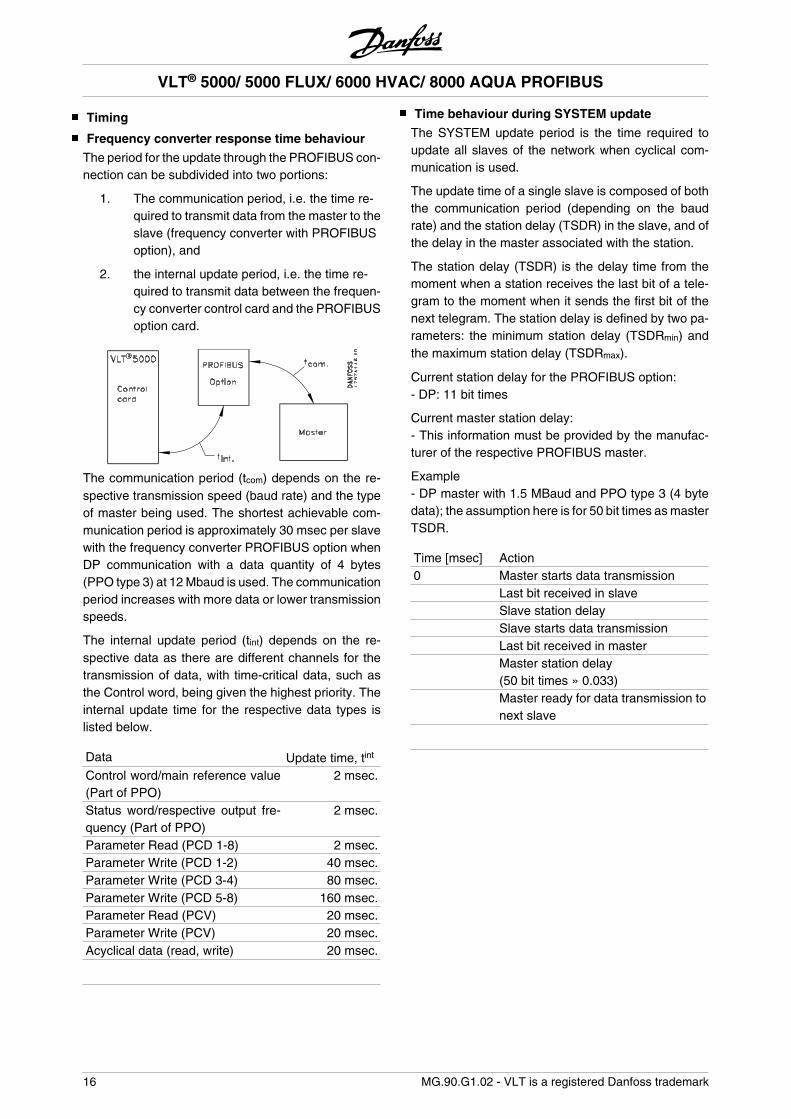
The period for the update through the PROFIBUS con-nection can be subdivided into two portions:
1. The communication period, i.e. the time re-quired to transmit data from the master to theslave (frequency converter with PROFIBUSoption), and
2. the internal update period, i.e. the time re-quired to transmit data between the frequen-cy converter control card and the PROFIBUSoption card.
The communication period (tcom) depends on the re-spective transmission speed (baud rate) and the typeof master being used. The shortest achievable com-munication period is approximately 30 msec per slavewith the frequency converter PROFIBUS option whenDP communication with a data quantity of 4 bytes(PPO type 3) at 12 Mbaud is used. The communicationperiod increases with more data or lower transmissionspeeds.
The internal update period (tint) depends on the re-spective data as there are different channels for thetransmission of data, with time-critical data, such asthe Control word, being given the highest priority. Theinternal update time for the respective data types islisted below.
Data Update time, tint
Control word/main reference value(Part of PPO)
2 msec.
Status word/respective output fre-quency (Part of PPO)
2 msec.
Parameter Read (PCD 1-8) 2 msec.Parameter Write (PCD 1-2) 40 msec.Parameter Write (PCD 3-4) 80 msec.Parameter Write (PCD 5-8) 160 msec.Parameter Read (PCV) 20 msec.Parameter Write (PCV) 20 msec.Acyclical data (read, write) 20 msec.
Time behaviour during SYSTEM update
The SYSTEM update period is the time required toupdate all slaves of the network when cyclical com-munication is used.
The update time of a single slave is composed of boththe communication period (depending on the baudrate) and the station delay (TSDR) in the slave, and ofthe delay in the master associated with the station.
The station delay (TSDR) is the delay time from themoment when a station receives the last bit of a tele-gram to the moment when it sends the first bit of thenext telegram. The station delay is defined by two pa-rameters: the minimum station delay (TSDRmin) andthe maximum station delay (TSDRmax).
Current station delay for the PROFIBUS option:- DP: 11 bit times
Current master station delay:- This information must be provided by the manufac-turer of the respective PROFIBUS master.
Example- DP master with 1.5 MBaud and PPO type 3 (4 bytedata); the assumption here is for 50 bit times as masterTSDR.
Time [msec] Action0 Master starts data transmission Last bit received in slave Slave station delay Slave starts data transmission Last bit received in master Master station delay
(50 bit times » 0.033) Master ready for data transmission to
next slave
VLT® 5000/ 5000 FLUX/ 6000 HVAC/ 8000 AQUA PROFIBUS
16 MG.90.G1.02 - VLT is a registered Danfoss trademark
Communication connections
Communication pursuant to PROFIBUS DP, i.e.EN50170 part 3, is supported.
Accordingly, a master must be used that supportsPROFIBUS DP.
PPO description (Overview)
A feature of the PROFIBUS profile for frequency con-verters is a communications object designated as”PPO”, i.e. ”parameter process data object”.
All cyclical informative data are transmitted via PPOs.Thus, PPOs form the framework for the data traffic.One of the PPOs described in the following must beused in the case of DP communication.
The actual PPO type can be readout in parameter 904.
A PPO may consist of a parameter portion and a proc-ess data portion. The parameter portion may be usedfor reading and/or updating of parameters (succes-sively).
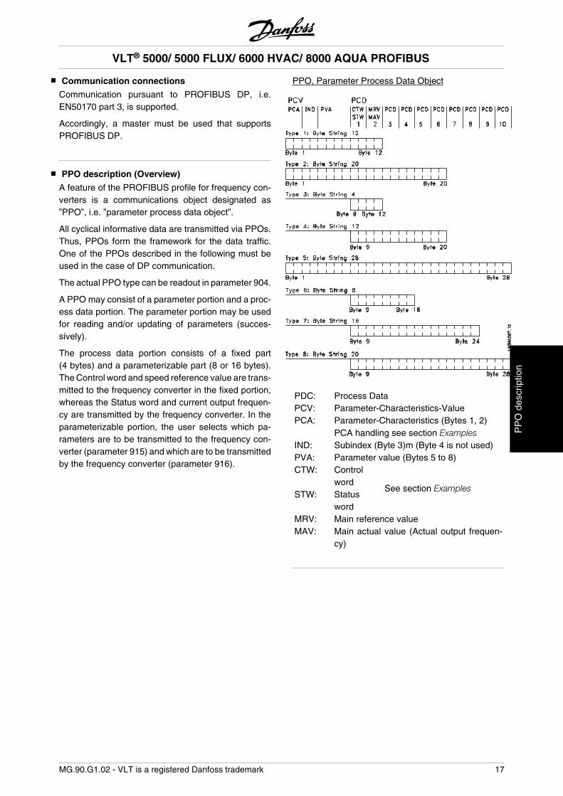
The process data portion consists of a fixed part(4 bytes) and a parameterizable part (8 or 16 bytes).The Control word and speed reference value are trans-mitted to the frequency converter in the fixed portion,whereas the Status word and current output frequen-cy are transmitted by the frequency converter. In theparameterizable portion, the user selects which pa-rameters are to be transmitted to the frequency con-verter (parameter 915) and which are to be transmittedby the frequency converter (parameter 916).
PPO, Parameter Process Data Object
PDC: Process DataPCV: Parameter-Characteristics-ValuePCA: Parameter-Characteristics (Bytes 1, 2)
PCA handling see section ExamplesIND: Subindex (Byte 3)m (Byte 4 is not used)PVA: Parameter value (Bytes 5 to 8)CTW: Control
wordSee section Examples
STW: Statusword
MRV: Main reference valueMAV: Main actual value (Actual output frequen-
cy)
VLT® 5000/ 5000 FLUX/ 6000 HVAC/ 8000 AQUA PROFIBUS
MG.90.G1.02 - VLT is a registered Danfoss trademark 17
PP
O d
escr
iptio
n
PCA processing
The master controls and monitors frequency converterparameters through the PCA portion of the PPOs type1, 2 and 5 and requests a response from the frequencyconverter (slave). In addition to the parameter pro-cessing, the frequency converter can also transmit aspontaneous message.
Requests and responses involve an acknowledgementexchange (a so-called handshake) which cannot beworked off in stack operation. This means that themaster, when sending a read/write request, must waitfor the response before sending a new request. A re-quest or response is limited to a maximum of 4 bytes,i.e. no text strings can be transmitted.
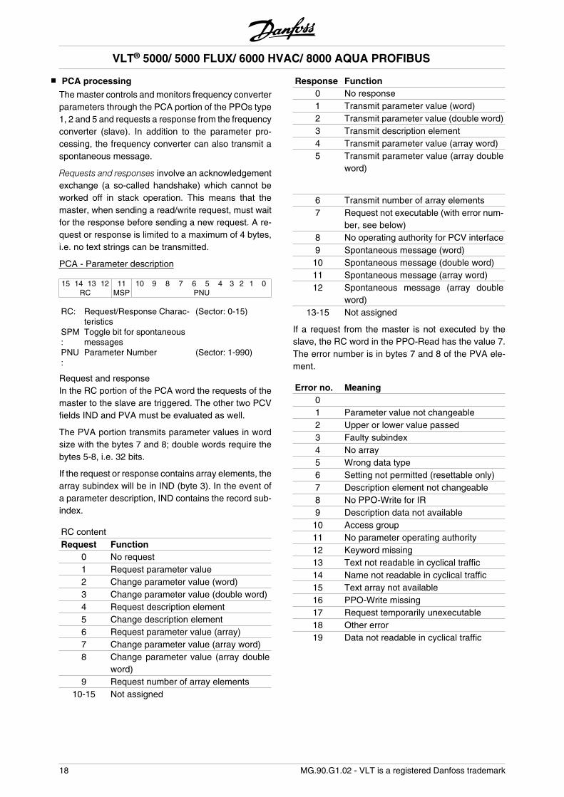
PCA - Parameter description
15 14 13 12 11 10 9 8 7 6 5 4 3 2 1 0RC MSP PNU
RC: Request/Response Charac-teristics
(Sector: 0-15)
SPM:
Toggle bit for spontaneousmessages
PNU:
Parameter Number (Sector: 1-990)
Request and responseIn the RC portion of the PCA word the requests of themaster to the slave are triggered. The other two PCVfields IND and PVA must be evaluated as well.
The PVA portion transmits parameter values in wordsize with the bytes 7 and 8; double words require thebytes 5-8, i.e. 32 bits.
If the request or response contains array elements, thearray subindex will be in IND (byte 3). In the event ofa parameter description, IND contains the record sub-index.
RC contentRequest Function
0 No request1 Request parameter value2 Change parameter value (word)3 Change parameter value (double word)4 Request description element5 Change description element6 Request parameter value (array)7 Change parameter value (array word)8 Change parameter value (array double
word)9 Request number of array elements
10-15 Not assigned
Response Function0 No response1 Transmit parameter value (word)2 Transmit parameter value (double word)3 Transmit description element4 Transmit parameter value (array word)5 Transmit parameter value (array double
word)
6 Transmit number of array elements7 Request not executable (with error num-
ber, see below)8 No operating authority for PCV interface9 Spontaneous message (word)
10 Spontaneous message (double word)11 Spontaneous message (array word)12 Spontaneous message (array double
word)13-15 Not assigned
If a request from the master is not executed by theslave, the RC word in the PPO-Read has the value 7.The error number is in bytes 7 and 8 of the PVA ele-ment.
Error no. Meaning0 1 Parameter value not changeable2 Upper or lower value passed3 Faulty subindex4 No array5 Wrong data type6 Setting not permitted (resettable only)7 Description element not changeable8 No PPO-Write for IR9 Description data not available
10 Access group11 No parameter operating authority12 Keyword missing13 Text not readable in cyclical traffic14 Name not readable in cyclical traffic15 Text array not available16 PPO-Write missing17 Request temporarily unexecutable18 Other error19 Data not readable in cyclical traffic
VLT® 5000/ 5000 FLUX/ 6000 HVAC/ 8000 AQUA PROFIBUS
18 MG.90.G1.02 - VLT is a registered Danfoss trademark
Parameters and data type structures
Parameter description
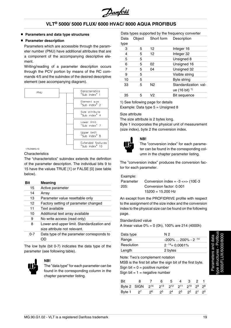
Parameters which are accessible through the param-eter number (PNU) have additional attributes that area component of the accompanying descriptive ele-ment.Writing/reading of a parameter description occursthrough the PCV portion by means of the RC com-mands 4/5 and the subindex of the desired descriptiveelement (see accompanying diagram).
CharacteristicsThe “characteristics” subindex extends the definitionof the parameter description. The individual bits 9 to15 have the values TRUE [1] or FALSE [0] (see tablebelow).
Bit Meaning15 Active parameter14 Array13 Parameter value resettable only12 Factory setting of parameter changed11 Text available10 Additional text array available9 No write access (read only)8 Lower and upper limit. Standardization and
size attribute not relevant.0-7 Data type of the parameter corresponds to
OD
The low byte (bit 0-7) indicates the data type of theparameter (see following table).
NB!The ”data type” for each parameter can befound in the corresponding column in thechapter parameter listing.
Data types supported by the frequency converterDatatype
Object Short form Description
3 5 12 Integer 164 5 12 Integer 325 5 Unsigned 86 5 02 Unsigned 167 5 04 Unsigned 329 5 Visible string
10 5 Byte string33 5 N2 Standardization val-
ue (16 bit) 1)
35 5 V2 Bit sequence
1) See following page for detailsExample: Data type 5 = Unsigned 8
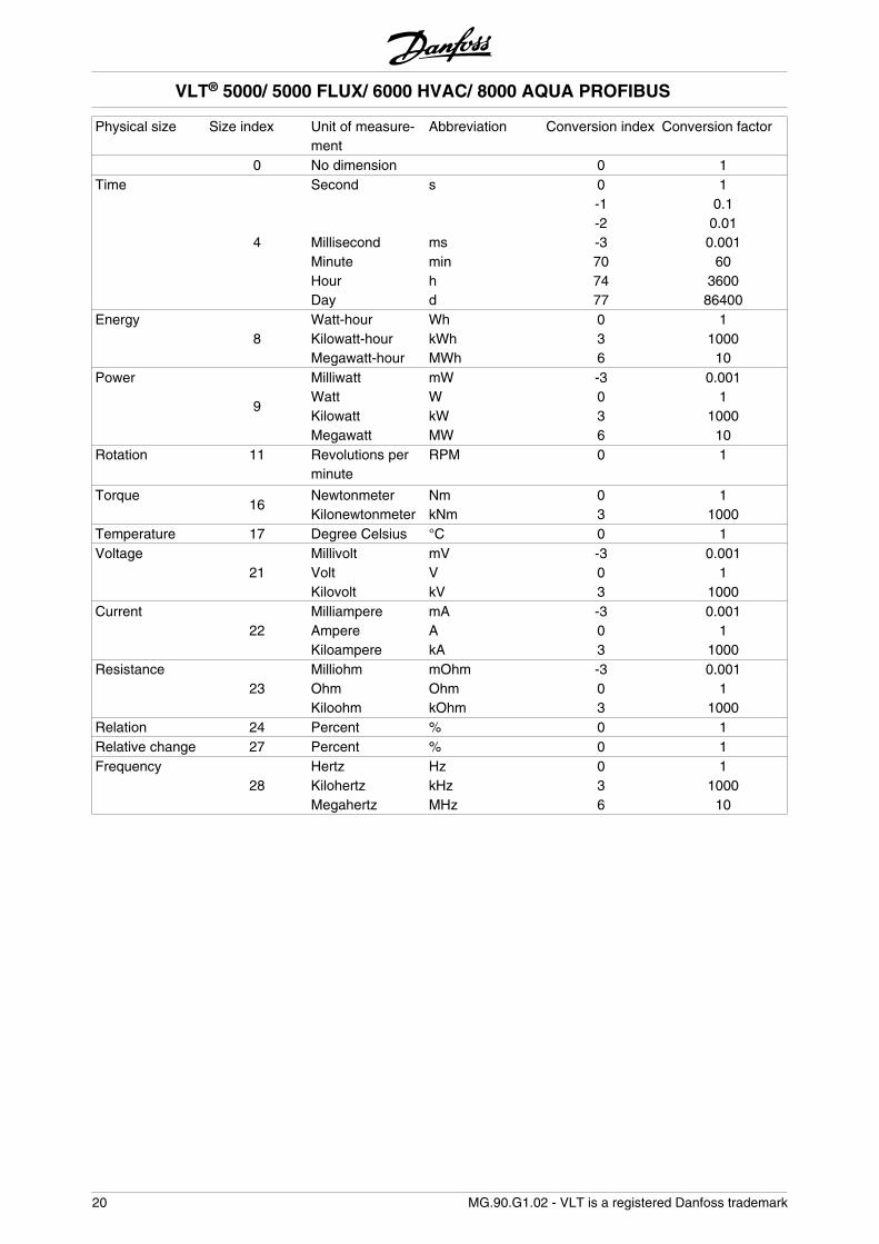
Size attributeThe size attribute is 2 bytes long.Byte 1 incorporates the physical unit of measurement(size index), byte 2 the conversion index.
NB!The ”conversion index” for each parame-ter can be found in the corresponding col-umn in the chapter parameter listing.
The ”conversion index” produces the conversion fac-tor for each parameter.
Example: Parameter205:
Conversion index = -3 <=> (10E-3Conversion factor: 0.00115200 = 15.200 Hz
An except from the PROFIDRIVE profile with respectto the assignment of the size index and the conversionindex to the physical size can be found on the followingpage.
Standardized valueA linear value 0% = 0 (0h), 100% are 214 (4000h)
Data type N 2Range -200% ... 200% - 2 -14
Resolution 2 -14= 0,0061%Length 2 bytes
Note: Two’s complement notationMSB is the first bit after the sign bit of the first byte.Sign bit = 0 = positive numberSign bit = 1 = negative number
Bit 8 7 6 5 4 3 2 1Byte 2 SIGN 214 213 212 211 210 29 28
Byte 1 27 26 25 24 23 22 21 20
VLT® 5000/ 5000 FLUX/ 6000 HVAC/ 8000 AQUA PROFIBUS
MG.90.G1.02 - VLT is a registered Danfoss trademark 19
Par
amet
ers
and
data
type
str
uctu
res
- P
rofib
us50
00/F
LUX
/600
0/80
00
Physical size Size index Unit of measure-ment
Abbreviation Conversion index Conversion factor
0 No dimension 0 1Time
4
Second s 0 1 -1 0.1 -2 0.01 Millisecond ms -3 0.001 Minute min 70 60 Hour h 74 3600 Day d 77 86400Energy
8Watt-hour Wh 0 1
Kilowatt-hour kWh 3 1000 Megawatt-hour MWh 6 10Power
9
Milliwatt mW -3 0.001 Watt W 0 1 Kilowatt kW 3 1000 Megawatt MW 6 10Rotation 11 Revolutions per
minuteRPM 0 1
Torque16
Newtonmeter Nm 0 1 Kilonewtonmeter kNm 3 1000Temperature 17 Degree Celsius °C 0 1Voltage
21Millivolt mV -3 0.001
Volt V 0 1 Kilovolt kV 3 1000Current
22Milliampere mA -3 0.001
Ampere A 0 1 Kiloampere kA 3 1000Resistance
23Milliohm mOhm -3 0.001
Ohm Ohm 0 1 Kiloohm kOhm 3 1000Relation 24 Percent % 0 1Relative change 27 Percent % 0 1Frequency
28Hertz Hz 0 1
Kilohertz kHz 3 1000 Megahertz MHz 6 10
VLT® 5000/ 5000 FLUX/ 6000 HVAC/ 8000 AQUA PROFIBUS
20 MG.90.G1.02 - VLT is a registered Danfoss trademark
Spontaneous messages
The spontaneous message is triggered by the activealarm and warning words parameters in the actualdrive. The PCV response indicates the parameternumber (PNU) and the parameter value (PVA) of themodified active parameter that triggered the message.
Spontaneous messages are generated when activeparameters are changed, i.e. a message occurs whena warning appears and when a warning disappears.
At the same time, the frequency converter modifies theSPM bit (11) of the PCV word (see ”PCA processing”).
The spontaneous messages are transmitted until themaster has confirmed the receipt of the message andchanged the SPM bit.
NB!Spontaneous messages are only activa-ted when the parameter 917 is in the ”ON”position. In the event of an activated spon-taneous message, the parameter channelis blocked until the spontaneous messagehas been acknowledged by the master.
Example of a spontaneous message for VLT 5000Observation of the parameter channel (PCV) from the PPO (without index field):
PCV (Hex) PVA (Hex) from Master from fre-quency con-verter
Description
12 08 00 00 00 00 x The master requests the current of the frequencyconverter
12 08 00 00 00 F0 x The frequency converter current value: 2.4 Amp(parameter 520)
12 08 00 00 00 00 x The master requests the current of the frequencyconverter
AC 1A 00 00 00 0A x The frequency converter has a spontaneous mes-sage, the spontaneous message bit is set, thePNU 538 (alarm word) has the value 000A (Hex)
1C 08 00 00 00 00 x The master requests the current of the frequencyconverter and acknowledges the spontaneousmessage by ”toggling” the SPM in the PCV
1C 08 00 00 00 F0 x The frequency converter current value: 2.4 Amp,the spontaneous message bit remains at ”1” untilthe next spontaneous message; the spontaneousmessage is acknowledged.
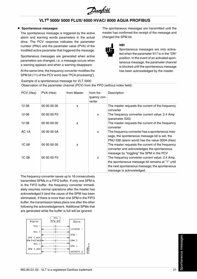
The frequency converter saves up to 16 consecutivelytransmitted SPMs in a FIFO buffer. If only one SPM isin the FIFO buffer, the frequency converter immedi-ately resumes normal operations after the master hasacknowledged it (and the cause of the SPM has beeneliminated). If there is more than one SPM in the FIFObuffer, the transmission takes place one after the otherfollowing the acknowledgement. Additional SPMs thatare generated while the buffer is full will be ignored.
VLT® 5000/ 5000 FLUX/ 6000 HVAC/ 8000 AQUA PROFIBUS
MG.90.G1.02 - VLT is a registered Danfoss trademark 21 Spo
ntan
eous
mes
sage
s
SYNC and FREEZE
The control commands SYNC/UNSYNC (SYN-CHRONIZE/CANCEL SYNCHRONIZATION) andFREEZE/UNFREEZE are broadcast functions. SYNC/UNSYNC is used to transmit synchronized controlcommands and/or speed reference values to all con-nected slaves. FREEZE/UNFREEZE is used to freezethe status actual value in the slaves in order to receivea synchronized actual value from all connected slaves.
The SYNC and FREEZE commands refer to the PCDand PCV portions of the PPO.
SYNC/UNSYNC
By using SYNC/UNSYNC, simultaneous responses ofseveral slaves can be generated, e.g. synchronizedstart, stop, or change of the speed. In the event of aSYNC command, the current Control word and thespeed reference value are frozen. Incoming processdata are saved, but are only applied when a new SYNCcommand or an UNSYNC command is made.The following example shows the speed reference val-ue sent by the master in the left column and the re-spective effective speed reference value for the threeslaves in the three columns to the right.
Current speed reference value slaveFrom DP master to address: VLT
Address 3 VLT
Address 4 VLT
Address 51. Speed reference value = 50% to address 3 • 50% 0 % 0 %2. Speed reference value = 50% to address 4 50% • 50% 0 %3. Speed reference value = 50% to address 5 50% 50% • 50%4. SYNC command to all addresses • 50% • 50% • 50%5. Speed reference value = 75% to address 3 • 50% 50% 50%6. Speed reference value = 75% to address 4 50% • 50% 50%7. Speed reference value = 75% to address 5 50% 50% • 50%8. SYNC command to all addresses • 75 % • 75 % • 75 %9. Speed reference value = 100% to address 3 • 75 % 75 % 75 %10. Speed reference value = 50% to address 4 75 % • 75 % 75 %11. Speed reference value = 25% to address 5 75 % 75 % • 75 %12. UNSYNC command to all addresses • 100 % • 50 % • 25 %13. Speed reference = 0% to address 3 • 0 % 50 % 25 %14. Speed reference = 0% to address 4 0 % • 0 % 25 %15. Speed reference = 0% to address 5 0 % 0 % • 0 %
FREEZE/UNFREEZE
By using FREEZE/UNFREEZE, simultaneous readingof process data, e.g. output current, by several slavescan be brought about. At a FREEZE command, theactual current values are frozen. When instructed, theslave will send back the value in effect at the time theFREEZE command was issued. The respective values
are updated when a new FREEZE command or anUNFREEZE command is issued.The following example shows the current values readby the master in the left column and the respective ef-fective value of the output current for the three slavesin the three columns to the right.
VLT® 5000/ 5000 FLUX/ 6000 HVAC/ 8000 AQUA PROFIBUS
22 MG.90.G1.02 - VLT is a registered Danfoss trademark
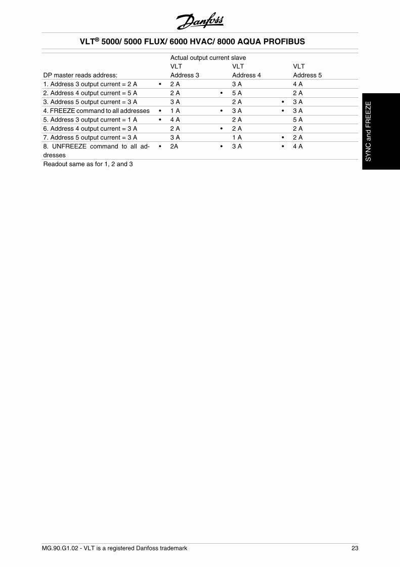
Actual output current slave VLT VLT VLTDP master reads address: Address 3 Address 4 Address 51. Address 3 output current = 2 A • 2 A 3 A 4 A2. Address 4 output current = 5 A 2 A • 5 A 2 A3. Address 5 output current = 3 A 3 A 2 A • 3 A4. FREEZE command to all addresses • 1 A • 3 A • 3 A5. Address 3 output current = 1 A • 4 A 2 A 5 A6. Address 4 output current = 3 A 2 A • 2 A 2 A7. Address 5 output current = 3 A 3 A 1 A • 2 A8. UNFREEZE command to all ad-dresses
• 2A • 3 A • 4 A
Readout same as for 1, 2 and 3
VLT® 5000/ 5000 FLUX/ 6000 HVAC/ 8000 AQUA PROFIBUS
MG.90.G1.02 - VLT is a registered Danfoss trademark 23
SY
NC
and
FR
EE
ZE
Control word/Status word
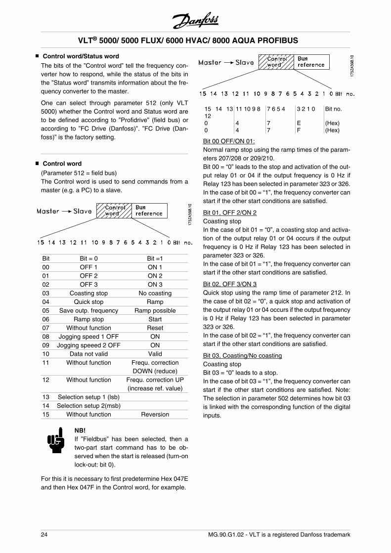
The bits of the ”Control word” tell the frequency con-verter how to respond, while the status of the bits inthe ”Status word” transmits information about the fre-quency converter to the master.
One can select through parameter 512 (only VLT5000) whether the Control word and Status word areto be defined according to ”Profidrive” (field bus) oraccording to ”FC Drive (Danfoss)”. ”FC Drive (Dan-foss)” is the factory setting.
Control word
(Parameter 512 = field bus)The Control word is used to send commands from amaster (e.g. a PC) to a slave.
Bit Bit = 0 Bit =100 OFF 1 ON 101 OFF 2 ON 202 OFF 3 ON 303 Coasting stop No coasting04 Quick stop Ramp05 Save outp. frequency Ramp possible06 Ramp stop Start07 Without function Reset08 Jogging speed 1 OFF ON09 Jogging speeed 2 OFF ON10 Data not valid Valid11 Without function Frequ. correction
DOWN (reduce)12 Without function Frequ. correction UP
(increase ref. value)13 Selection setup 1 (lsb) 14 Selection setup 2(msb) 15 Without function Reversion
NB!If ”Fieldbus” has been selected, then atwo-part start command has to be ob-served when the start is released (turn-onlock-out: bit 0).
For this it is necessary to first predetermine Hex 047Eand then Hex 047F in the Control word, for example.
15 14 1312
11 10 9 8 7 6 5 4 3 2 1 0 Bit no.
0 4 7 E (Hex)0 4 7 F (Hex)
Bit 00 OFF/ON 01:Normal ramp stop using the ramp times of the param-eters 207/208 or 209/210.Bit 00 = “0” leads to the stop and activation of the out-put relay 01 or 04 if the output frequency is 0 Hz ifRelay 123 has been selected in parameter 323 or 326.In the case of bit 00 = “1”, the frequency converter canstart if the other start conditions are satisfied.
Bit 01, OFF 2/ON 2Coasting stopIn the case of bit 01 = “0”, a coasting stop and activa-tion of the output relay 01 or 04 occurs if the outputfrequency is 0 Hz if Relay 123 has been selected inparameter 323 or 326.In the case of bit 01 = “1”, the frequency converter canstart if the other start conditions are satisfied.
Bit 02, OFF 3/ON 3Quick stop using the ramp time of parameter 212. Inthe case of bit 02 = “0”, a quick stop and activation ofthe output relay 01 or 04 occurs if the output frequencyis 0 Hz if Relay 123 has been selected in parameter323 or 326.In the case of bit 02 = “1”, the frequency converter canstart if the other start conditions are satisfied.
Bit 03, Coasting/No coastingCoasting stopBit 03 = “0” leads to a stop.In the case of bit 03 = “1”, the frequency converter canstart if the other start conditions are satisfied. Note:The selection in parameter 502 determines how bit 03is linked with the corresponding function of the digitalinputs.
VLT® 5000/ 5000 FLUX/ 6000 HVAC/ 8000 AQUA PROFIBUS
24 MG.90.G1.02 - VLT is a registered Danfoss trademark
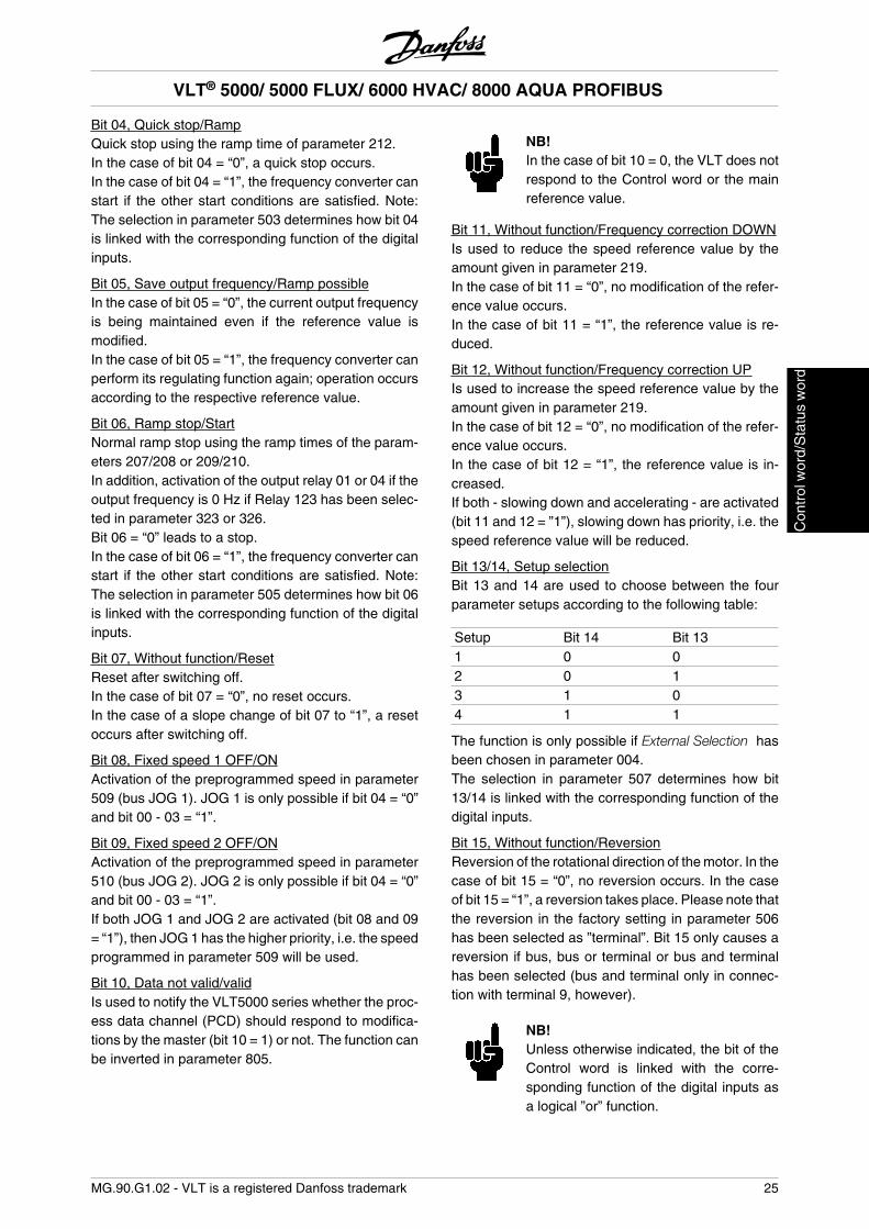
Bit 04, Quick stop/RampQuick stop using the ramp time of parameter 212.In the case of bit 04 = “0”, a quick stop occurs.In the case of bit 04 = “1”, the frequency converter canstart if the other start conditions are satisfied. Note:The selection in parameter 503 determines how bit 04is linked with the corresponding function of the digitalinputs.
Bit 05, Save output frequency/Ramp possibleIn the case of bit 05 = “0”, the current output frequencyis being maintained even if the reference value ismodified.In the case of bit 05 = “1”, the frequency converter canperform its regulating function again; operation occursaccording to the respective reference value.
Bit 06, Ramp stop/StartNormal ramp stop using the ramp times of the param-eters 207/208 or 209/210.In addition, activation of the output relay 01 or 04 if theoutput frequency is 0 Hz if Relay 123 has been selec-ted in parameter 323 or 326.Bit 06 = “0” leads to a stop.In the case of bit 06 = “1”, the frequency converter canstart if the other start conditions are satisfied. Note:The selection in parameter 505 determines how bit 06is linked with the corresponding function of the digitalinputs.
Bit 07, Without function/ResetReset after switching off.In the case of bit 07 = “0”, no reset occurs.In the case of a slope change of bit 07 to “1”, a resetoccurs after switching off.
Bit 08, Fixed speed 1 OFF/ONActivation of the preprogrammed speed in parameter509 (bus JOG 1). JOG 1 is only possible if bit 04 = “0”and bit 00 - 03 = “1”.
Bit 09, Fixed speed 2 OFF/ONActivation of the preprogrammed speed in parameter510 (bus JOG 2). JOG 2 is only possible if bit 04 = “0”and bit 00 - 03 = “1”.If both JOG 1 and JOG 2 are activated (bit 08 and 09= “1”), then JOG 1 has the higher priority, i.e. the speedprogrammed in parameter 509 will be used.
Bit 10, Data not valid/validIs used to notify the VLT5000 series whether the proc-ess data channel (PCD) should respond to modifica-tions by the master (bit 10 = 1) or not. The function canbe inverted in parameter 805.
NB!In the case of bit 10 = 0, the VLT does notrespond to the Control word or the mainreference value.
Bit 11, Without function/Frequency correction DOWNIs used to reduce the speed reference value by theamount given in parameter 219.In the case of bit 11 = “0”, no modification of the refer-ence value occurs.In the case of bit 11 = “1”, the reference value is re-duced.
Bit 12, Without function/Frequency correction UPIs used to increase the speed reference value by theamount given in parameter 219.In the case of bit 12 = “0”, no modification of the refer-ence value occurs.In the case of bit 12 = “1”, the reference value is in-creased.If both - slowing down and accelerating - are activated(bit 11 and 12 = ”1”), slowing down has priority, i.e. thespeed reference value will be reduced.
Bit 13/14, Setup selectionBit 13 and 14 are used to choose between the fourparameter setups according to the following table:
Setup Bit 14 Bit 131 0 02 0 13 1 04 1 1
The function is only possible if External Selection hasbeen chosen in parameter 004.The selection in parameter 507 determines how bit13/14 is linked with the corresponding function of thedigital inputs.
Bit 15, Without function/ReversionReversion of the rotational direction of the motor. In thecase of bit 15 = “0”, no reversion occurs. In the caseof bit 15 = “1”, a reversion takes place. Please note thatthe reversion in the factory setting in parameter 506has been selected as ”terminal”. Bit 15 only causes areversion if bus, bus or terminal or bus and terminalhas been selected (bus and terminal only in connec-tion with terminal 9, however).
NB!Unless otherwise indicated, the bit of theControl word is linked with the corre-sponding function of the digital inputs asa logical ”or” function.
VLT® 5000/ 5000 FLUX/ 6000 HVAC/ 8000 AQUA PROFIBUS
MG.90.G1.02 - VLT is a registered Danfoss trademark 25
Con
trol
wor
d/S
tatu
s w
ord
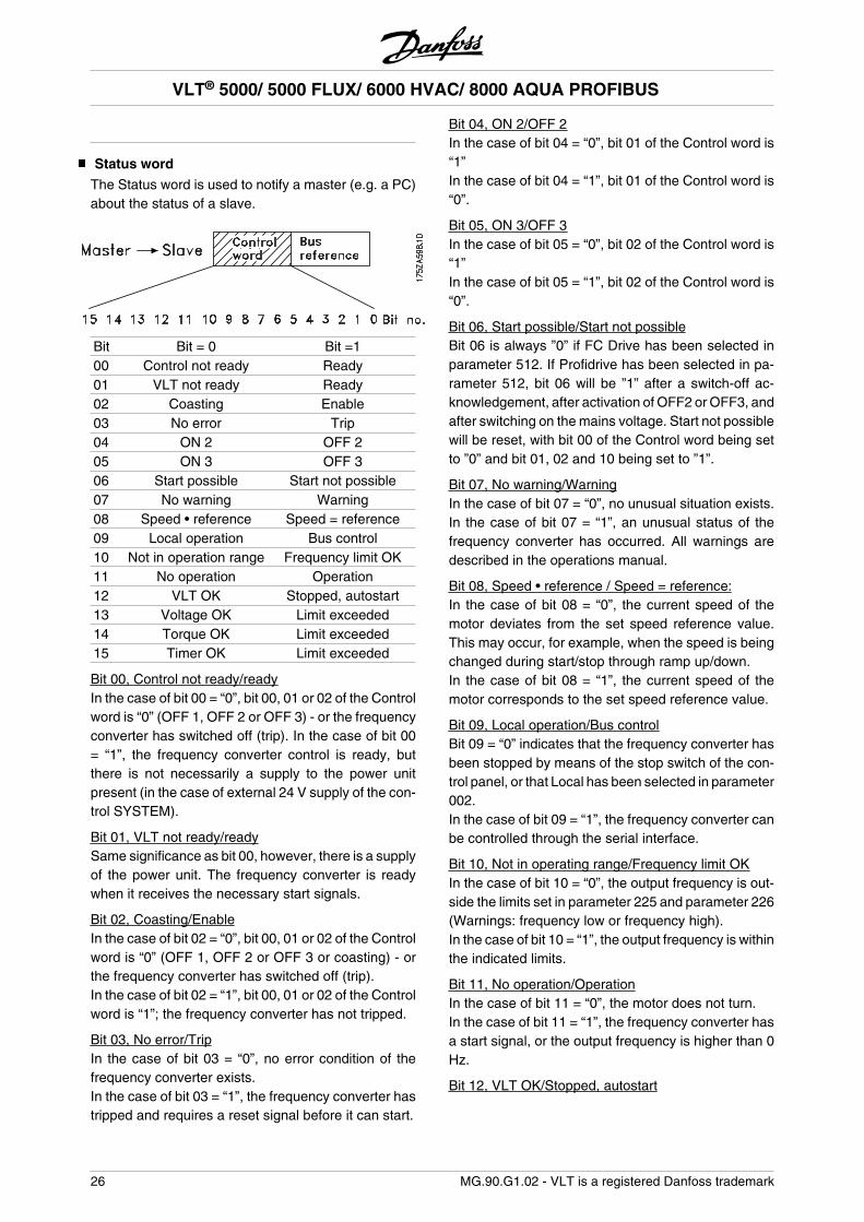
Status word
The Status word is used to notify a master (e.g. a PC)about the status of a slave.
Bit Bit = 0 Bit =100 Control not ready Ready01 VLT not ready Ready02 Coasting Enable03 No error Trip04 ON 2 OFF 205 ON 3 OFF 306 Start possible Start not possible07 No warning Warning08 Speed • reference Speed = reference09 Local operation Bus control10 Not in operation range Frequency limit OK11 No operation Operation12 VLT OK Stopped, autostart13 Voltage OK Limit exceeded14 Torque OK Limit exceeded15 Timer OK Limit exceeded
Bit 00, Control not ready/readyIn the case of bit 00 = “0”, bit 00, 01 or 02 of the Controlword is “0” (OFF 1, OFF 2 or OFF 3) - or the frequencyconverter has switched off (trip). In the case of bit 00= “1”, the frequency converter control is ready, butthere is not necessarily a supply to the power unitpresent (in the case of external 24 V supply of the con-trol SYSTEM).
Bit 01, VLT not ready/readySame significance as bit 00, however, there is a supplyof the power unit. The frequency converter is readywhen it receives the necessary start signals.
Bit 02, Coasting/EnableIn the case of bit 02 = “0”, bit 00, 01 or 02 of the Controlword is “0” (OFF 1, OFF 2 or OFF 3 or coasting) - orthe frequency converter has switched off (trip).In the case of bit 02 = “1”, bit 00, 01 or 02 of the Controlword is “1”; the frequency converter has not tripped.
Bit 03, No error/TripIn the case of bit 03 = “0”, no error condition of thefrequency converter exists.In the case of bit 03 = “1”, the frequency converter hastripped and requires a reset signal before it can start.
Bit 04, ON 2/OFF 2In the case of bit 04 = “0”, bit 01 of the Control word is“1”In the case of bit 04 = “1”, bit 01 of the Control word is“0”.
Bit 05, ON 3/OFF 3In the case of bit 05 = “0”, bit 02 of the Control word is“1”In the case of bit 05 = “1”, bit 02 of the Control word is“0”.
Bit 06, Start possible/Start not possibleBit 06 is always ”0” if FC Drive has been selected inparameter 512. If Profidrive has been selected in pa-rameter 512, bit 06 will be ”1” after a switch-off ac-knowledgement, after activation of OFF2 or OFF3, andafter switching on the mains voltage. Start not possiblewill be reset, with bit 00 of the Control word being setto ”0” and bit 01, 02 and 10 being set to ”1”.
Bit 07, No warning/WarningIn the case of bit 07 = “0”, no unusual situation exists.In the case of bit 07 = “1”, an unusual status of thefrequency converter has occurred. All warnings aredescribed in the operations manual.
Bit 08, Speed • reference / Speed = reference:In the case of bit 08 = “0”, the current speed of themotor deviates from the set speed reference value.This may occur, for example, when the speed is beingchanged during start/stop through ramp up/down.In the case of bit 08 = “1”, the current speed of themotor corresponds to the set speed reference value.
Bit 09, Local operation/Bus controlBit 09 = “0” indicates that the frequency converter hasbeen stopped by means of the stop switch of the con-trol panel, or that Local has been selected in parameter002.In the case of bit 09 = “1”, the frequency converter canbe controlled through the serial interface.
Bit 10, Not in operating range/Frequency limit OKIn the case of bit 10 = “0”, the output frequency is out-side the limits set in parameter 225 and parameter 226(Warnings: frequency low or frequency high).In the case of bit 10 = “1”, the output frequency is withinthe indicated limits.
Bit 11, No operation/OperationIn the case of bit 11 = “0”, the motor does not turn.In the case of bit 11 = “1”, the frequency converter hasa start signal, or the output frequency is higher than 0Hz.
Bit 12, VLT OK/Stopped, autostart
VLT® 5000/ 5000 FLUX/ 6000 HVAC/ 8000 AQUA PROFIBUS
26 MG.90.G1.02 - VLT is a registered Danfoss trademark
In the case of bit 12 = “0”, there is no temporary over-loading of the inverter.In the case of bit 12 = “1”, the inverter has stopped dueto overloading. However, the frequency converter hasnot switched off (trip) and will start again after the over-loading has ended.
Bit 13, Voltage OK/Limit exceededIn the case of bit 13 = “0”, the voltage limits of the fre-quency converter are not exceeded.In the case of bit 13 = “1”, the direct voltage in the in-termediate circuit of the frequency converter is too lowor too high.
Bit 14, Moment OK/Limit exceededIn the case of bit 14 = “0”, the motor current is belowthe moment limit selected in parameter 221.In the case of bit 14 = “1”, the moment limit selected inparameter 221 is exceeded.
Bit 15, Timer OK/Limit exceededIn the case of bit 15 = “0”, the timers for the thermalmotor protection and thermal frequency converter pro-tection have not exceeded 100%. In the case of bit 15= “1”, one of the timers has exceeded 100%.
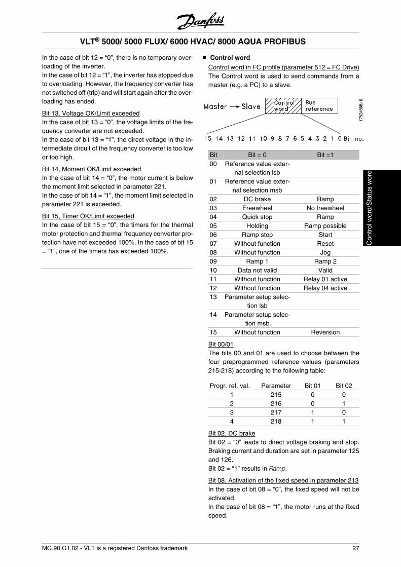
Control word
Control word in FC profile (parameter 512 = FC Drive)The Control word is used to send commands from amaster (e.g. a PC) to a slave.
Bit Bit = 0 Bit =100 Reference value exter-
nal selection lsb
01 Reference value exter-nal selection msb
02 DC brake Ramp03 Freewheel No freewheel04 Quick stop Ramp05 Holding Ramp possible06 Ramp stop Start07 Without function Reset08 Without function Jog09 Ramp 1 Ramp 210 Data not valid Valid11 Without function Relay 01 active12 Without function Relay 04 active13 Parameter setup selec-
tion lsb
14 Parameter setup selec-tion msb
15 Without function Reversion
Bit 00/01The bits 00 and 01 are used to choose between thefour preprogrammed reference values (parameters215-218) according to the following table:
Progr. ref. val. Parameter Bit 01 Bit 021 215 0 02 216 0 13 217 1 04 218 1 1
Bit 02, DC brakeBit 02 = “0” leads to direct voltage braking and stop.Braking current and duration are set in parameter 125and 126.Bit 02 = “1” results in Ramp.
Bit 08, Activation of the fixed speed in parameter 213In the case of bit 08 = “0”, the fixed speed will not beactivated.In the case of bit 08 = “1”, the motor runs at the fixedspeed.
VLT® 5000/ 5000 FLUX/ 6000 HVAC/ 8000 AQUA PROFIBUS
MG.90.G1.02 - VLT is a registered Danfoss trademark 27
Con
trol
wor
d/S
tatu
s w
ord
Bit 09, Ramp selection 1/2In the case of bit 09 = “0”, ramp 1 is active (parameter207/208).In the case of bit 09 = “1”, ramp 2 is active (parameter209/210).
Bit 11, Relay 01Bit 11 = “0”: Relay 01 is not activated.Bit 11 = “1”: Relay 01 is activated, on the pre-conditionthat Control word bit was selected in parameter 323.
Bit 12, Relay 04Bit 12 = “0”: Relay 04 is not activated.Bit 12 = “1”: Relay 04 is activated, on the pre-conditionthat Control word bit was selected in parameter 326.
NB!The description of the other bits can befound in the section ”Control word accord-ing to Profidrive”.
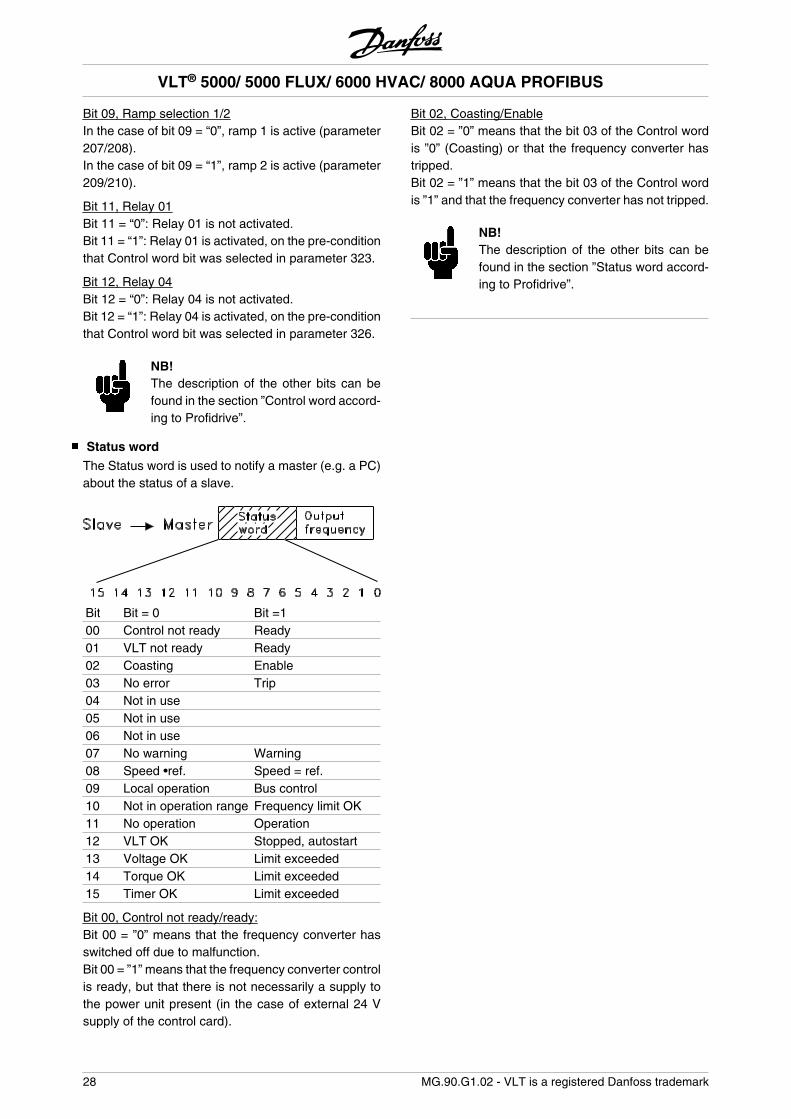
Status word
The Status word is used to notify a master (e.g. a PC)about the status of a slave.
Bit Bit = 0 Bit =100 Control not ready Ready01 VLT not ready Ready02 Coasting Enable03 No error Trip04 Not in use 05 Not in use 06 Not in use 07 No warning Warning08 Speed •ref. Speed = ref.09 Local operation Bus control10 Not in operation range Frequency limit OK11 No operation Operation12 VLT OK Stopped, autostart13 Voltage OK Limit exceeded14 Torque OK Limit exceeded15 Timer OK Limit exceeded
Bit 00, Control not ready/ready:Bit 00 = ”0” means that the frequency converter hasswitched off due to malfunction.Bit 00 = ”1” means that the frequency converter controlis ready, but that there is not necessarily a supply tothe power unit present (in the case of external 24 Vsupply of the control card).
Bit 02, Coasting/EnableBit 02 = ”0” means that the bit 03 of the Control wordis ”0” (Coasting) or that the frequency converter hastripped.Bit 02 = ”1” means that the bit 03 of the Control wordis ”1” and that the frequency converter has not tripped.
NB!The description of the other bits can befound in the section ”Status word accord-ing to Profidrive”.
VLT® 5000/ 5000 FLUX/ 6000 HVAC/ 8000 AQUA PROFIBUS
28 MG.90.G1.02 - VLT is a registered Danfoss trademark
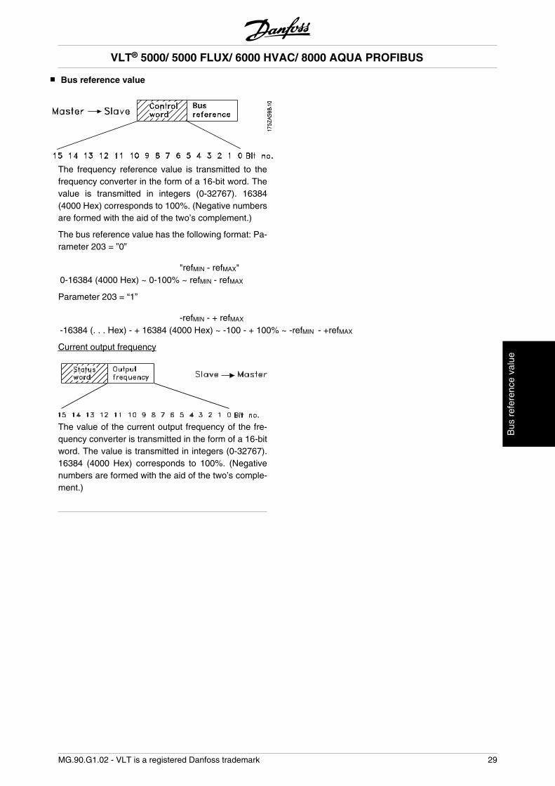
Bus reference value
The frequency reference value is transmitted to thefrequency converter in the form of a 16-bit word. Thevalue is transmitted in integers (0-32767). 16384(4000 Hex) corresponds to 100%. (Negative numbersare formed with the aid of the two’s complement.)
The bus reference value has the following format: Pa-rameter 203 = ”0”
"refMIN - refMAX"0-16384 (4000 Hex) ~ 0-100% ~ refMIN - refMAX
Parameter 203 = “1”
-refMIN - + refMAX
-16384 (. . . Hex) - + 16384 (4000 Hex) ~ -100 - + 100% ~ -refMIN - +refMAX
Current output frequency
The value of the current output frequency of the fre-quency converter is transmitted in the form of a 16-bitword. The value is transmitted in integers (0-32767).16384 (4000 Hex) corresponds to 100%. (Negativenumbers are formed with the aid of the two’s comple-ment.)
VLT® 5000/ 5000 FLUX/ 6000 HVAC/ 8000 AQUA PROFIBUS
MG.90.G1.02 - VLT is a registered Danfoss trademark 29
Bus
ref
eren
ce v
alue
Example 1: PCV Channel
This example shows how PPO type 1 is used forchanging the ramp-up time (parameter 207) to 10 sec-onds and for commanding a start and speed referenceof 50%.
Frequency converter parameter settings:P502: serial portP512: Fieldbus profile (Profidrive profile) = factory set-tingPlease see section PPO description.
PCD: Process Data PVA: Parameter value (Bytes 5 to 8)PCV: Parameter-Characteristics Value CTW: Control wordPCA: Parameter-Characteristics (Bytes 1. 2)
PCA handling below STW: Status word
IND: Subindex (Byte 3), (Byte 4 is not used) MRV: Main reference value MAV: Main actual value
In the configuration of the PPO types (informative datatelegrams), a distinction is made between module con-sistency and word consistency:
Module consistency means that a particular portion ofthe PPO is defined as a connected module. The pa-rameter interface (PCV, length 8 byte) of the PPOalways has module consistency.
Word consistency means that a particular portion ofthe PPO is divided into individual data sectors of wordsize (16 bit).
The process data (PCD) of the PPO can have eithermodule consistency or word consistency, as desired.
Some PLCs, such as the Siemens S7, require specialfunctions to address modules that are longer than 4byte (in the case of Siemens: ”SFC”, see Master Man-ual).This means that, in the case of Siemens (S7), the PCVinterface of the PPOs can only be addressed throughthe SFC functions.
PCV
PCA Parameter characteristics
RC: Request/Response (Range: 0-15)SPM: Toggle bit for spontaneous mes-
sages
PNU: Parameter Number (Range: 1-990)
PCA portion (byte 1-2)The RC portion determines what the PCV portion is tobe used for.If a parameter needs to be changed, value 2 or 3 mustbe selected; here, 3 was selected since parameter 207refers to a double word (32 bits).
SPM bitIn the example, the function “spontaneous messages”is not needed (parameter 917 = OFF) and thus theSPM bit is set to 0.
PNU = Parameter Number The parameter number isset to: 207 = CF Hex. This means that the value for theentire PCA portion is 30CF Hex.
IND (bytes 3-4)This is used in reading/changing of parameters withsubindex, e.g. in the case of parameter 915. In the ex-ample, the bytes 3 and 4 are set to 00Hex.
PVA (bytes 5-8)Changing the data value of parameter 207 to 10.00 s.The transmitted value must be 1000, since the con-
version index for parameter 207 is -2, i.e. the valuereceived by the frequency converter is divided by 100so that the frequency converter ”understands” 1000 as10.00. 1000 corresponds to 03E8Hex.
PCD (Process Data)
CTW (Control Word)The following bit patterns set all necessary start com-mands:15 .... ...0 <=> Bit number0 000 0100 0111 111 1 <=> 047FHex.
MRV (Main Reference Value)Speed reference value, the data format is “standar-dized value”.0Hex = 0% and 4000Hex = 100%.
For example, 2000Hex correspond to 50% of the max-imum frequency (parameter 202).
The entire PPO being sent from the master to the fre-quency converter thus has the following hexadecimalvalues:
VLT® 5000/ 5000 FLUX/ 6000 HVAC/ 8000 AQUA PROFIBUS
30 MG.90.G1.02 - VLT is a registered Danfoss trademark
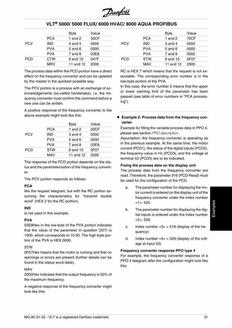
Byte Value PCA 1 and 2 30CFPCV IND 3 and 4 0000 PVA 5 and 6 0000 PVA 7 and 8 03E8PCD CTW 9 and 10 047F MRV 11 and 12 2000
The process data within the PCD portion have a directeffect on the frequency converter and can be updatedby the master in the quickest possible way.
The PCV portion is a process with an exchange of ac-knowledgements (so-called handshake), i.e. the fre-quency converter must confirm the command before anew one can be written.
A positive response of the frequency converter to theabove example might look like this:
Byte Value PCA 1 and 2 20CFPCV IND 3 and 4 0000 PVA 5 and 6 0000 PVA 7 and 8 03E8PCD STW 9 and 10 0F07 MAV 11 and 12 2000
The response of the PCD portion depends on the sta-tus and the parameterization of the frequency convert-er.
The PCV portion responds as follows:
PCAlike the request telegram, but with the RC portion as-suming the characteristics for ”transmit doubleword” (HEX 2 for the RC portion).
INDis not used in this example.
PVA03E8Hex in the low-byte of the PVA portion indicatesthat the value of the parameter in question (207) is1000, which corresponds to 10.00. The high-byte por-tion of the PVA is HEX 0000.
STW0F07Hex means that the motor is running and that nowarnings or errors are present (further details can befound in the status word table).
MAV2000Hex indicates that the output frequency is 50% ofthe maximum frequency.
A negative response of the frequency converter mightlook like this:
Byte Value PCA 1 and 2 70CFPCV IND 3 and 4 0000 PVA 5 and 6 0000 PVA 7 and 8 0002PCD STW 9 and 10 0F07 MAV 11 and 12 2000
RC is HEX 7 which means that the request is not ex-ecutable. The corresponding error number is in thelow-byte portion of the PVA.In this case, the error number 2 means that the upperor lower warning limit of the parameter has beenpassed (see table of error numbers in ”PCA process-ing”).
Example 2: Process data from the frequency con-verter
Example for filling the variable process data in PPO 4,please see section PPO description.Assumption: the frequency converter is operating asin the previous example. At the same time, the motorcurrent (PCD1), the status of the digital inputs (PCD2),the frequency value in Hz (PCD3), and the voltage atterminal 53 (PCD4) are to be indicated.
Fixing the process data on the display unitThe process data from the frequency converter areread. Therefore, the parameter 916 (PCD-Read) mustbe used for the configuration of the PCD.
a. The parameter number for displaying the mo-tor current is entered on the display unit of thefrequency converter under the index number<1>: 520.
b. The parameter number for displaying the dig-ital inputs is entered under the index number<2>: 528.
c. Index number <3> = 518 (display of the fre-quency)
d. Index number <4> = 529 (display of the volt-age at input 53)
Frequency converter response PPO type 4For example, the frequency converter response of aPPO 4 telegram after the configuration might look likethis:
VLT® 5000/ 5000 FLUX/ 6000 HVAC/ 8000 AQUA PROFIBUS
MG.90.G1.02 - VLT is a registered Danfoss trademark 31
Exa
mpl
es
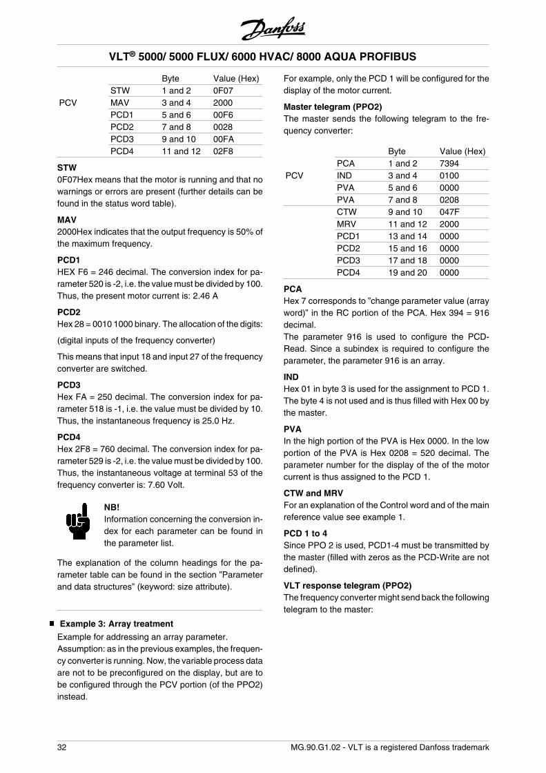
Byte Value (Hex) STW 1 and 2 0F07PCV MAV 3 and 4 2000 PCD1 5 and 6 00F6 PCD2 7 and 8 0028 PCD3 9 and 10 00FA PCD4 11 and 12 02F8
STW0F07Hex means that the motor is running and that nowarnings or errors are present (further details can befound in the status word table).
MAV2000Hex indicates that the output frequency is 50% ofthe maximum frequency.
PCD1HEX F6 = 246 decimal. The conversion index for pa-rameter 520 is -2, i.e. the value must be divided by 100.Thus, the present motor current is: 2.46 A
PCD2Hex 28 = 0010 1000 binary. The allocation of the digits:
(digital inputs of the frequency converter)
This means that input 18 and input 27 of the frequencyconverter are switched.
PCD3Hex FA = 250 decimal. The conversion index for pa-rameter 518 is -1, i.e. the value must be divided by 10.Thus, the instantaneous frequency is 25.0 Hz.
PCD4Hex 2F8 = 760 decimal. The conversion index for pa-rameter 529 is -2, i.e. the value must be divided by 100.Thus, the instantaneous voltage at terminal 53 of thefrequency converter is: 7.60 Volt.
NB!Information concerning the conversion in-dex for each parameter can be found inthe parameter list.
The explanation of the column headings for the pa-rameter table can be found in the section ”Parameterand data structures” (keyword: size attribute).
Example 3: Array treatment
Example for addressing an array parameter.Assumption: as in the previous examples, the frequen-cy converter is running. Now, the variable process dataare not to be preconfigured on the display, but are tobe configured through the PCV portion (of the PPO2)instead.
For example, only the PCD 1 will be configured for thedisplay of the motor current.
Master telegram (PPO2)The master sends the following telegram to the fre-quency converter:
Byte Value (Hex) PCA 1 and 2 7394PCV IND 3 and 4 0100 PVA 5 and 6 0000 PVA 7 and 8 0208 CTW 9 and 10 047F MRV 11 and 12 2000 PCD1 13 and 14 0000 PCD2 15 and 16 0000 PCD3 17 and 18 0000 PCD4 19 and 20 0000
PCAHex 7 corresponds to ”change parameter value (arrayword)” in the RC portion of the PCA. Hex 394 = 916decimal.The parameter 916 is used to configure the PCD-Read. Since a subindex is required to configure theparameter, the parameter 916 is an array.
INDHex 01 in byte 3 is used for the assignment to PCD 1.The byte 4 is not used and is thus filled with Hex 00 bythe master.
PVAIn the high portion of the PVA is Hex 0000. In the lowportion of the PVA is Hex 0208 = 520 decimal. Theparameter number for the display of the of the motorcurrent is thus assigned to the PCD 1.
CTW and MRVFor an explanation of the Control word and of the mainreference value see example 1.
PCD 1 to 4Since PPO 2 is used, PCD1-4 must be transmitted bythe master (filled with zeros as the PCD-Write are notdefined).
VLT response telegram (PPO2)The frequency converter might send back the followingtelegram to the master:
VLT® 5000/ 5000 FLUX/ 6000 HVAC/ 8000 AQUA PROFIBUS
32 MG.90.G1.02 - VLT is a registered Danfoss trademark
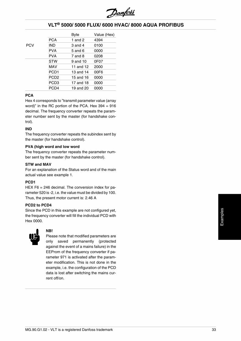
Byte Value (Hex) PCA 1 and 2 4394PCV IND 3 and 4 0100 PVA 5 and 6 0000 PVA 7 and 8 0208 STW 9 and 10 0F07 MAV 11 and 12 2000 PCD1 13 and 14 00F6 PCD2 15 and 16 0000 PCD3 17 and 18 0000 PCD4 19 and 20 0000
PCAHex 4 corresponds to ”transmit parameter value (arrayword)” in the RC portion of the PCA. Hex 394 = 916decimal. The frequency converter repeats the param-eter number sent by the master (for handshake con-trol).
INDThe frequency converter repeats the subindex sent bythe master (for handshake control).
PVA (high word and low wordThe frequency converter repeats the parameter num-ber sent by the master (for handshake control).
STW and MAVFor an explanation of the Status word and of the mainactual value see example 1.
PCD1HEX F6 = 246 decimal. The conversion index for pa-rameter 520 is -2, i.e. the value must be divided by 100.Thus, the present motor current is: 2.46 A
PCD2 to PCD4Since the PCD in this example are not configured yet,the frequency converter will fill the individual PCD withHex 0000.
NB!Please note that modified parameters areonly saved permanently (protectedagainst the event of a mains failure) in theEEProm of the frequency converter if pa-rameter 971 is activated after the param-eter modification. This is not done in theexample, i.e. the configuration of the PCDdata is lost after switching the mains cur-rent off/on.
VLT® 5000/ 5000 FLUX/ 6000 HVAC/ 8000 AQUA PROFIBUS
MG.90.G1.02 - VLT is a registered Danfoss trademark 33
Exa
mpl
es
DP V1 Identifications
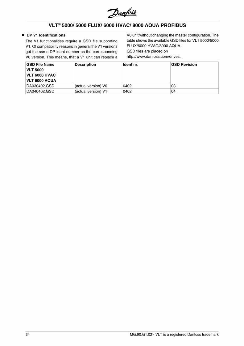
The V1 functionalities require a GSD file supportingV1. Of compatibility reasons in general the V1 versionsgot the same DP ident number as the correspondingV0 version. This means, that a V1 unit can replace a
V0 unit without changing the master configuration. Thetable shows the available GSD files for VLT 5000/5000FLUX/6000 HVAC/8000 AQUA.GSD files are placed onhttp://www.danfoss.com/drives.
GSD File NameVLT 5000VLT 6000 HVACVLT 8000 AQUA
Description Ident nr. GSD Revision
DA030402.GSD (actual version) V0 0402 03DA040402.GSD (actual version) V1 0402 04
VLT® 5000/ 5000 FLUX/ 6000 HVAC/ 8000 AQUA PROFIBUS
34 MG.90.G1.02 - VLT is a registered Danfoss trademark
VLT frequency converter parameters
Only the parametergroups (800 and 900) are descri-bed in this manual. For any other parameters of theVLT 5000 series/VLT 5000 Flux, VLT 6000 HVAC/VLT8000 AQUA and their functions, please refer to theVLT 5000/5000 Flux/6000 HVAC/8000 AQUA seriesoperations manual.
NB!Please pay special attention to the follow-ing parameters which are not described inthis manual:
002: In the case of local operation, a controlvia PROFIBUS is not possible.
502-508: Selection of how the PROFIBUS controlcommands are to be linked with the con-trol commands of the digital inputs of thecontrol card.
512: Control word profile, selection of a Con-trol word according to FIELDBUS or ac-cording to a Control word specified byDanfoss.
515-538: Data output parameters which can beused for the display of a variety of cur-rent data of the frequency converter,e.g. current status of the analog and dig-ital inputs of the control card and, there-fore, their usage as inputs for themaster.
800 Protocol selsction
(PROTOCOL SELECT)
Value:
Read only
Function:Selection of the PROFIBUS protocol supported by themaster
Description of choice:DP: Communication according to EN 50170, part 3
NB!In the event of an update of parameter800, from LCP or FC bus even with an un-changed data value, the PROFIBUS op-tion is initialized, which means that allcommunication parameters, e.g. slaveaddress, are being updated. The commu-nication is being reset and the previous
changed address parameter 918 will bevalid.
803 Time after bus error
(BUS TIME OUT)
Value:1 - 99 sec. 1 sec.
804 Response after bus error
(TIME OUT FUNCT.)
Value:
Off (OFF) [0]
Freeze output frequency (FREEZE OUTPUT) [1]
Stop with auto restart (STOP) [2]
Output frequency = JOG frequency (JOG-GING) [3]
Output freq. = Max. freq. (MAX SPEED) [4]
Stop with trip (STOP AND TRIP) [5]
Control without PROFIBUS(NO COM OPT CONTROL) [6]
Select setup 4 (SELECT SETUP 4) [7]
Select setup 2 (SELECT SETUP 2) [8]
Function:The timeout counter is activated at the first receipt ofa valid Control word, i.e. bit 10 = OK. In case of anacyclic DP V1 communication the timeout function willnot be triggered.
The Timeout function can be activated in two ways:1. CTW is not updated within the specified time.2. Parameter 805 = “Bit 10 = 0 Þ Timeout” and bit 10= “0”.
The frequency converter remains in the timeout statusuntil one of the following four conditions occurs.1. A valid Control word (bit 10 = OK) is received and areset (bus, terminals or control panel) is activated (re-set is only necessary if the timeout function Stop withtrip was selected) • control via PROFIBUS is resumedwith the current Control word.2. Parameter 002 = Local operation • local controlthrough control panel is active.3. Parameter 928 = Not active • normal control throughterminals and RS 485 is active.
VLT® 5000/ 5000 FLUX/ 6000 HVAC/ 8000 AQUA PROFIBUS
= factory setting, () = display text, [] = value for use in communication via serial communication port
MG.90.G1.02 - VLT is a registered Danfoss trademark 35
Par
amet
ers
NB!The timeout counter is reset and needs tobe triggered by a valid Control word beforea new timeout can be activated.
4. Parameter 804 = Off • control via PROFIBUS is re-sumed, with the Control word used last being taken.
Description of choice:- Save output frequency: Save (‘freeze’) the output fre-quency until communication resumes.- Stop with auto restart: Stop with automatic restart onresumption of communication.-Output frequency = Fixed speed frequency: Motor runswith fixed speed frequency until resumption of com-munication.-Output frequency = max. frequency: Motor runs withthe maximum frequency until resumption of communi-cation.- Stop with trip: Motor has stopped, a reset is neces-sary for a restart, see explanation above.- Control without PROFIBUS: Control via PROFIBUS isinactive; control is possible via the terminals and/or theRS 485 standard interface until communication re-sumes.- Selection parameter setup 4: Parameter setup 4 isselected in parameter 004; the settings of parametersetup 4 are used.Parameter 004 is not reset to the original value uponresumption of communication.- Selection parameter setup 2: Parameter setup 2 isselected in parameter 004; the settings of parametersetup 2 are used.Parameter 004 is not reset to the original value uponresumption of communication.
805 Function Control word bit 10
(BIT 10 FUNCT.)
Value:
Without function(NO FUNCTION) [0]
Bit 10 = 1 • CTW active(BIT 10 = 1 • CTW ACTIVE) [1]
Bit 10 = 0 • CTW active(BIT 10 = 0 • CTW ACTIVE) [2]
Bit 10 = 0 • Timeout(BIT 10 = 0 • TIMEOUT) [3]
Function:According to the PROFIDRIVE profile, the Controlword and speed reference value are ignored when bit10 of the Control word is 0. However, a modification ofthe function of bit 10 is possible through parameter805.
This is sometimes necessary since some masters setall bits to 0 in different error situations. In these casesit makes sense to change the function of bit 10 so thatthe command to stop (coasting) goes to the frequencyconverter if all bits are 0.
Description of choice:
- Bit 10 = 1 • CTW active: If bit 10 = 0, the Con-trol word and speed reference value are ig-nored.
- Bit 10 = 0 • CTW active: If bit 10 = 1, the Con-trol word and speed reference value are ig-nored. If all bits of the Control word are 0, thefrequency converter will switch to coasting inresponse here to.
- Bit 10 = 0 • Timeout: If bit 10 = 0, the timeoutfunction selected in parameter 804 is activa-ted.
- Without function: Bit 10 is ignored, i.e. theControl word and speed reference value arealways valid.
NB!During an update of parameter 800 or dur-ing the next turn-on procedure, the pa-rameter 805 changes too.
808 Profidrive Status word
(PROFIDRV STATUSW)
Value:
Off 2/3 Non inverted (OFF2/3 NON-INVER-TED) [0]
Off 2/3 Inverted (OFF2/3 INVERTED) [1]
Function:This function makes it possible to invert Off 2 and Off3 bits in the Profidrive Status Word, if Fieldbus profileis selected in p. 512.
Description of choice:Off 2/3 Non inverted: Off 2/3 bits are inverted contraryto Profidrive profile.
VLT® 5000/ 5000 FLUX/ 6000 HVAC/ 8000 AQUA PROFIBUS
= factory setting, () = display text, [] = value for use in communication via serial communication port
36 MG.90.G1.02 - VLT is a registered Danfoss trademark
Off 2/3 Inverted: Status word is according to Profidriveprofile.
849 Extend Diagnosis
(EXTEND DIAGNOSIS)
Value:
Disable (DISABLE) [0]
Alarm (ALARM) [1]
Alarm and Warning (ALARM AND WARNING) [2]
Function:This function allows to expand the diagnosis data to24 Byte, if this parameter is set to Alarm [1] and Alarmsand Warnings [2].
Description of choice:Please refer to the section Extended diagnosis in thismanual.
904 PPO type select for DP
(PPO TYPE SELECT)
Value:
PPO type 1 (PPO TYPE 1) [900]
PPO type 2 (PPO TYPE 2) [901]
PPO type 3 (PPO TYPE 3) [902]
PPO type 4 (PPO TYPE 4) [903]
PPO type 5 (PPO TYPE 5) [905]
PPO type 6 (PPO TYPE 6) [906]
PPO type 7 (PPO TYPE 7) [907]
PPO type 8 (PPO TYPE 8) [908]
Function:Read out of PPO type set by the master.
Description of choice:- PPO type 1: 12 byte PPO with parameter channel forread and write of parameters and 4 bytes of processdata (Control/Status word and reference/actual outputfrequency).- PPO type 2: 20 byte PPO as PPO type 1 with 8 ad-ditional bytes of selectable process data.-PPO type 3: 4 byte process data (Control/Status wordand reference/actual output frequency).-PPO type 4: 12 byte process data, as process datapart of PPO type 2.- PPO type 5: 28 byte as PPO type 2 with 8 additionalbytes of selectable process data.
- PPO type 6: 8 byte Control/Status word and refer-ence/actual output frequency and additional 4 byteprocess data.- PPO type 7: 16 byte Control/Status word and refer-ence/actual output frequency and additional 12 byteprocess data.- PPO type 8: 20byte Control/Status word and refer-ence/actual output frequency and additional 16 byteprocess data.
A detailed description of the PPO types can be foundin the section PPO description (Overview).
915 PCD config. write
(PCD IN WR-)
Selections:
Sub index 1 (PCD3) Parameter #Sub index 2 Parameter #Sub index 3 Parameter #Sub index 4 Parameter #Sub index 5 Parameter #Sub index 6 Parameter #Sub index 7 Parameter #Sub index 8 Parameter #
Function:Different parameters may be assigned to the PCD3-10 of the PPOs (the max.number of the PCD de-pends on the PPO type). The values in PCD 3-10 arewritten to the selected parameters in form of data val-ues.
Write access to parameter 915 via Profibus or stand-ard RS 485 or LCP2.
Description of choice:The sequence of the sub-indexes corresponds to thesequence of the PCD in the PPO, i.e. sub-index1 = PCD 3, sub-index 2 = PCD 4 etc. Each sub-indexmay contain the number of any frequency converterparameter that can be written to.Each PCD is defined as a word. If data should be writ-ten to a parameter that has an attribute of Integer 32or Unsigned 32 the parameter number should be de-fined twice in the following PCD’s: PCD 3 and 4, PCD5 and 6, PCD 7 and 8 or PCD 9 and 10. See exampleby parameter 916 PCD config. Read.
VLT® 5000/ 5000 FLUX/ 6000 HVAC/ 8000 AQUA PROFIBUS
= factory setting, () = display text, [] = value for use in communication via serial communication port
MG.90.G1.02 - VLT is a registered Danfoss trademark 37
Par
amet
ers
NB!First the odd subindex must be written.Otherwise the data will be interpreted as2 low words.
916 PCD config. read
(PCD IN RD-)
Selections:
Sub index 1 (PCD3) Parameter #Sub index 2 Parameter #Sub index 3 Parameter #Sub index 4 Parameter #Sub index 5 Parameter #Sub index 6 Parameter #Sub index 7 Parameter #Sub index 8 Parameter #
Function:Different parameters may be assigned to the PCD3-10 of the PPOs (the max.number of the PCD de-pends on the PPO type). The values in PCD 3-10 areread from the selected parameters in form of data val-ues.
Write access to parameter 916 via Profibus or stand-ard RS 485 or LCP2.
Description of choice:The sequence of the sub-indexes corresponds to thesequence of the PCD in the PPO, i.e. sub-index 1 =PCD 3, sub-index 2 = PCD 4 etc. Each sub-index maycontain the number of any frequency converter pa-rameter.Each PCD is defined as a word. If data should be readfrom a parameter that has an attribute of Integer 32 orUnsigned 32 the parameter should be defined twice inthe following PCD’s: PCD 3 and 4, PCD 5 and 6, PCD7 and 8 or PCD 9 and 10.
NB!Note: The odd subindex must be writtenfirst. Otherwise the data will be interpretedas 2 low words.1
Example PPO type 6:PCD 1 CTW/STW PCD 2 MRV/MAV PCD 3 Par. 515 PCD 4 Par. 518 PCD 5 Par. 520 High wordPCD 6 Par. 520 Low wordPCD 7 Par. 538 High wordPCD 8 Par. 538 Low word
CTW/STW = Control word / Status word = 16 bitMRV/MAV = Main Reference Value / Main Actual Val-ue = 16 bitPar 515 Data readout: Reference % = Datatype 3 •Integer 16Par 518 data readout: Frequency = Datatype 3 • Inte-ger 16Par 520 Data readout= Motor current =Datatype 7 •Unsigned 32Par 538 Data readout: Alarm Word = Datatype 7 • Un-signed 32
917 Spontaneous/event messages
(SPONT. MESSAGE)
Value:
Off (OFF) [0]
On (ON) [1]
Function:The spontaneous and event messages may be switch-ed if the frequency converter is to report a message inthe event of a warning or alarm status. A descriptionof the spontaneous and event messages can be foundin section PCA processing.
Description of choice:- OFF: The frequency converter does not report aspontaneous or event message in the warning oralarm status.- ON: When PPOs are, the frequency converter reportsa spontaneous message in the event of a warning oralarm status.
918 Station address
(STATION ADDR)
Value:
0 -125
126
VLT® 5000/ 5000 FLUX/ 6000 HVAC/ 8000 AQUA PROFIBUS
= factory setting, () = display text, [] = value for use in communication via serial communication port
38 MG.90.G1.02 - VLT is a registered Danfoss trademark
Function:All stations connected to the same bus must have aunique address. The station address can be set in pa-rameter 918.
NB!A change in parameter 918 is executed atnext power up or if parameter 800 is up-dated. Please see section Station addressin this manual for further information.
927 PCV operating authority
(PARAMETER EDIT)
Value:
Disable [0]
Enable [1]
Function:The parameter channel PCV can be blocked so thatthe modification of parameters through this channel isnot possible. Access through the standard RS 485 in-terface is still possible.
NB!When parameters 927 and 928 are deac-tivated, the ”Warning 34” in the display ofthe frequency converter will also be sup-pressed.
Description of choice:- Disable: Parameter processing through the PROFI-BUS is not active.- Enable: Parameter processing through the PROFI-BUS is active.
928 Control authority
(PROCESS CONTROL)
Value:
Disable [0]
Enable [1]
Function:The process control (adjustment of Control wordspeed reference value and of the following variablePCD) can be blocked. Control through the control cardterminals is still possible via the terminals, dependingon how the parameters 502-508 have been program-med.
NB!When parameters 927 and 928 are deac-tivated, the “Warning 34” in the display ofthe frequency converter will also be sup-pressed.
Description of choice:If Disable [0] is selected, process control through Pro-fibus is not active, but standard RS 485 is active. IfEnable [1] is selected, process control through Profi-bus is active, but standard RS 485 is not active.
NB!Please note, that the motor may start with-out advance warning when parameter 928has been changed, and start commandsare present.
953 Warning parameter 1
(WARN. PARA)
Value:
Read only
Function:In this parameter it is possible to read out warningmessages via standard bus or Profibus. This param-eter is not available via LCP, but the warning messagecan be seen by choosing Com warning word as displayreadout. A bit is assigned to every warning (see thefollowing list).
VLT® 5000/ 5000 FLUX/ 6000 HVAC/ 8000 AQUA PROFIBUS
= factory setting, () = display text, [] = value for use in communication via serial communication port
MG.90.G1.02 - VLT is a registered Danfoss trademark 39
Par
amet
ers
Bit Bit= “1” when:0 LSB Connection with DP-master is not ok1 Not used2 FDL (Field-bus Data link Layer) is not ok3 Clear dat command received4 Actual value is not updated5 Spontaneous message FIFO overflow6 PROFIBUS ASIC is not transmitting7 Initialising of PROFIBUS option is not ok8 Not used9 Not used10 Not used11 Not used12 Fatal DPR-handling error/Error code dur-
ing init.: Bit 013 Fatal DPR-handling error/Error code dur-
ing init.: Bit 114 Fatal DPR-handling error/Error code dur-
ing init.: Bit 215 MSB Fatal DPR-handling error/Error code dur-
ing init.: Bit 3
Explanation of errror codes:Depending of Bit 7 the corresponding error codes canbe seen from Bit 12-15.
Bit 7 = 1: Initialisation failure
Code0 OK1 Init. channel not empty2 No resp. on command “Init. SPC3 controller”3 No resp. on command “No action”4 No resp. on writin ini.-data5 No valid resp. on writing init.-data6 No positive resp. on writing init.-data
Bit 7 = 0: Run time failure
Code0 OK1 Fatal error in warning channel2 Fatal error in spontaneous channel3 Fatal error in channel for input of process data4 Fatal error in channel for out of process data5 Fatal error in parameter channel 16 Fatal error in parameter channel 27 Fatal error in parameter channel 315 Fatal error in DPR form SPC3
964 Identification
Selections:
0 Manufucturer1 Device type2 Version3 Firmware date year4 Firmware date month5 Number of axes6 Profibus version7 Database version8 Power unit ID9 BMC software
Function:This parameter contains the identification of a Profibusslave. This parameter is read only and only accessiblevia the Profibus V1 communication.
965 Profile Number
(PROFILE NUMBER)
Value:
Profile number 1. octet Manufacturer [3]
Profile number 2. octet [3]
Function:This parameter contains the profile number which aProfibus slave supports. This parameter is read onlyand only accessible via the Profibus V1 communica-tion.
967 Control word
(CONTROL WORD)
Value:
16 bit binary code
No control panel access
Function:This parameter is read only and can only be accessedvia the Profibus communication.
968 Status word
(STATUS WORD)
Value:
Read only (16 bit binary code)
VLT® 5000/ 5000 FLUX/ 6000 HVAC/ 8000 AQUA PROFIBUS
= factory setting, () = display text, [] = value for use in communication via serial communication port
40 MG.90.G1.02 - VLT is a registered Danfoss trademark
No control panel access
Function:This parameter is read only and only accessible via theProfibus communication.
970 Edit setup selection
(EDIT SETUP SELECT)
Value:
Factory Setup [0]
Setup 1 (SETUP 1) [1]
Setup 2 (SETUP 2) [2]
Setup 3 (SETUP 3) [3]
Setup 4 (SETUP 4) [4]
Active setup (ACTIVE SETUP) [5]
Function:This parameter is to be used for accessing frequencyconverter parameters in various setups from a masterclass 1 (e.g. PLC).Please see section Read/Write on VLT frequency con-verter parameters.
971 Store data values
(STORE DATA VALUE)
Value:
No action (OFF) [0]
Store active setup (STORE ACTIVE SETUP) [1]
Store edit setup (STORE EDIT SETUP) [2]
Store all setups (STORE ALL SETUPS) [3]
Function:Parameter values modified through PROFIBUS mas-ter class 1 are only saved in RAM, i.e. the modificationsare lost in the event of a power failure. This parameteris used to activate a function by means of which allparameter values are saved in EEPROM, preservingthem even in the case of a power failure.
Description of choice:- No action: The function is not active.- Store active setup: All parameter setups of the activesetup are saved in EEPROM. The value returns to Notactive after all parameter values have been saved.- Store edit setup (par. 970): All parameter setups of thesetup being processed are saved in EEPROM. The
value returns to Not active after all parameter valueshave been saved.- Store all setups: All parameter setups in all setupsare saved in EEPROM. The value returns to Not activeafter all parameter values have been saved.
980-982 Defined parameters
(DEFINED PARAM.)
Value:
Read only
Function:The three parameters hold a list of all the parametersthat are defined in the VLT 5000/5000 FLUX/6000HVAC and 8000 AQUA. It is possible to read singleelements of the list by DP by using the correspondingsubindex. The subindexes start at 1 and follow the or-der of the parameter numbers.
Each parameter holds up to 116 elements (parameternumbers).
When a 0 is returned as parameter number the listends.
990-992 Modified parameters
(MODIFI. PARAM.)
Value:
Read only
Function:The three parameters hold a list of all the VLT5000/5000 FLUX/6000 HVAC and 8000 AQUA pa-rameters that have been changed from factory setting.It is possible to read single elements of the list by DPby using the corresponding subindex. The subindexesstart at 1 and follow the order of the parameter num-bers. Each parameter holds up to 116 elements (pa-rameter numbers). The number of parameters (990,991 and 992) in use depends on how many parame-ters have been changed from factory setting.
Read only parameters, as for example data read outparameters, will not be registered as modified even-though they are changing.
When a 0 is returned as parameter number the listends.
VLT® 5000/ 5000 FLUX/ 6000 HVAC/ 8000 AQUA PROFIBUS
= factory setting, () = display text, [] = value for use in communication via serial communication port
MG.90.G1.02 - VLT is a registered Danfoss trademark 41
Par
amet
ers
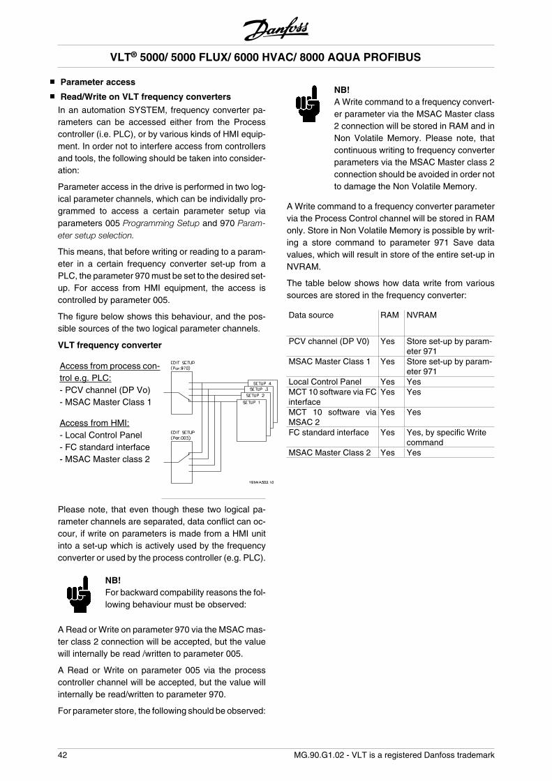
Parameter access
Read/Write on VLT frequency converters
In an automation SYSTEM, frequency converter pa-rameters can be accessed either from the Processcontroller (i.e. PLC), or by various kinds of HMI equip-ment. In order not to interfere access from controllersand tools, the following should be taken into consider-ation:
Parameter access in the drive is performed in two log-ical parameter channels, which can be individally pro-grammed to access a certain parameter setup viaparameters 005 Programming Setup and 970 Param-eter setup selection.
This means, that before writing or reading to a param-eter in a certain frequency converter set-up from aPLC, the parameter 970 must be set to the desired set-up. For access from HMI equipment, the access iscontrolled by parameter 005.
The figure below shows this behaviour, and the pos-sible sources of the two logical parameter channels.
VLT frequency converter
Access from process con-trol e.g. PLC:- PCV channel (DP Vo)- MSAC Master Class 1
Access from HMI:- Local Control Panel- FC standard interface- MSAC Master class 2
Please note, that even though these two logical pa-rameter channels are separated, data conflict can oc-cour, if write on parameters is made from a HMI unitinto a set-up which is actively used by the frequencyconverter or used by the process controller (e.g. PLC).
NB!For backward compability reasons the fol-lowing behaviour must be observed:
A Read or Write on parameter 970 via the MSAC mas-ter class 2 connection will be accepted, but the valuewill internally be read /written to parameter 005.
A Read or Write on parameter 005 via the processcontroller channel will be accepted, but the value willinternally be read/written to parameter 970.
For parameter store, the following should be observed:
NB!A Write command to a frequency convert-er parameter via the MSAC Master class2 connection will be stored in RAM and inNon Volatile Memory. Please note, thatcontinuous writing to frequency converterparameters via the MSAC Master class 2connection should be avoided in order notto damage the Non Volatile Memory.
A Write command to a frequency converter parametervia the Process Control channel will be stored in RAMonly. Store in Non Volatile Memory is possible by writ-ing a store command to parameter 971 Save datavalues, which will result in store of the entire set-up inNVRAM.
The table below shows how data write from varioussources are stored in the frequency converter:
Data source RAM NVRAM
PCV channel (DP V0) Yes Store set-up by param-eter 971
MSAC Master Class 1 Yes Store set-up by param-eter 971
Local Control Panel Yes YesMCT 10 software via FCinterface
Yes Yes
MCT 10 software viaMSAC 2
Yes Yes
FC standard interface Yes Yes, by specific Writecommand
MSAC Master Class 2 Yes Yes
VLT® 5000/ 5000 FLUX/ 6000 HVAC/ 8000 AQUA PROFIBUS
42 MG.90.G1.02 - VLT is a registered Danfoss trademark
Warnings and alarm messages
There is a clear distinction between alarm messagesand warnings. In the event of a fault (alarm), the fre-quency converter issues an error condition and re-sponds in the manner predetermined in the Controlword. As soon as the cause of the fault has been re-paired, the master must confirm the fault message forthe frequency converter in order to start again. A warn-ing is issued as soon as a warning condition occurs.This ceases as soon as the normal operating condi-tions have been re-established without the operationbeing disrupted.
WarningEvery warning within the frequency converter is rep-resented by a single bit in a warning word. A warningword is always an active parameter. The bit statusFALSE [0] means no warning, the bit status TRUE [1]means warning.
Every change of a bit in the warning word generates aspontaneous message.
Apart from the notification by the warning word, themaster is also being informed by a change in bit 7 ofthe Status word.
Fault messagesAfter a fault message (alarm), the frequency converterissues an error condition (bit 3 in the Status word). Thefrequency converter can resume operations only afterthe fault has been repaired and the master has con-firmed the fault message by a change of bit 7 in theControl word (positive slope from ”0” to ”1”).
Every fault within the frequency converter is represen-ted by a single bit in an alarm word. The alarm word isalways an active parameter. The bit status FALSE [0]means no alarm, the bit status TRUE [1] means alarm.
Every change of a bit in the alarm word generates aspontaneous message.
Spontaneous messages
If a fault or warning condition occurs, the frequencyconverter issues a spontaneous message providedthat the spontaneous message in parameter 917 hasbeen activated. Instead of responding to the requestfrom the master, the frequency converter replaces therequested response by the fault or warning message.
NB!Explanations regarding the individual bitsof the warning words and of the alarmword can be found in the Operationlnstructions of the VLT 5000 (MG.51.AX.YY), VLT 5000 FLUX (MG.
55.AX.YY), 6000 HVAC (MG.61.AX.YY)and 8000 AQUA (MG.83.AX.YY).
Additional display readings
If a frequency converter is equipped with a PROFIBUSinterface, it can display the following readings in addi-tion to the messages described in the VLT 5000/5000Flux/6000 HVAC/8000 AQUA product manual:
Warnings:WARN. 34PROFIBUS COMM. FAULT- There is no connection to the master. The reasoncould be that the master has stopped (or is in an errorstatus), or that the PROFIBUS connection to the fre-quency converter is interrupted.- There is an SPM overflow in the FIFO buffer for spon-taneous messages. (see ”Example of a spontaneousmessage”).
NB!When parameters 927 and 928 are deac-tivated, the ”Warning 34” in the display ofthe frequency converter will also be sup-pressed.
Alarm conditionsALARMPROFIBUS OPT. FAULT- The option card has been destroyed by electrical in-terference, or the option card is defective and needsto be replaced.
VLT® 5000/ 5000 FLUX/ 6000 HVAC/ 8000 AQUA PROFIBUS
MG.90.G1.02 - VLT is a registered Danfoss trademark 43
War
ning
and
ala
rm m
es-
sage
s
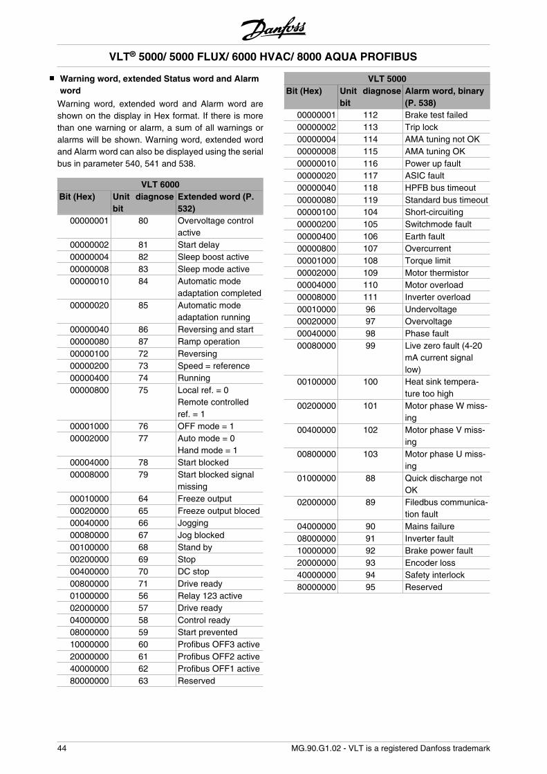
Warning word, extended Status word and Alarmword
Warning word, extended word and Alarm word areshown on the display in Hex format. If there is morethan one warning or alarm, a sum of all warnings oralarms will be shown. Warning word, extended wordand Alarm word can also be displayed using the serialbus in parameter 540, 541 and 538.
VLT 6000Bit (Hex) Unit diagnose
bitExtended word (P.532)
00000001 80 Overvoltage controlactive
00000002 81 Start delay00000004 82 Sleep boost active00000008 83 Sleep mode active00000010 84 Automatic mode
adaptation completed00000020 85 Automatic mode
adaptation running00000040 86 Reversing and start00000080 87 Ramp operation00000100 72 Reversing00000200 73 Speed = reference00000400 74 Running00000800 75 Local ref. = 0
Remote controlledref. = 1
00001000 76 OFF mode = 100002000 77 Auto mode = 0
Hand mode = 100004000 78 Start blocked00008000 79 Start blocked signal
missing00010000 64 Freeze output00020000 65 Freeze output bloced00040000 66 Jogging00080000 67 Jog blocked00100000 68 Stand by00200000 69 Stop00400000 70 DC stop00800000 71 Drive ready01000000 56 Relay 123 active02000000 57 Drive ready04000000 58 Control ready08000000 59 Start prevented10000000 60 Profibus OFF3 active20000000 61 Profibus OFF2 active40000000 62 Profibus OFF1 active80000000 63 Reserved
VLT 5000Bit (Hex) Unit diagnose
bitAlarm word, binary(P. 538)
00000001 112 Brake test failed00000002 113 Trip lock00000004 114 AMA tuning not OK00000008 115 AMA tuning OK00000010 116 Power up fault00000020 117 ASIC fault00000040 118 HPFB bus timeout00000080 119 Standard bus timeout00000100 104 Short-circuiting00000200 105 Switchmode fault00000400 106 Earth fault00000800 107 Overcurrent00001000 108 Torque limit00002000 109 Motor thermistor00004000 110 Motor overload00008000 111 Inverter overload00010000 96 Undervoltage00020000 97 Overvoltage00040000 98 Phase fault00080000 99 Live zero fault (4-20
mA current signallow)
00100000 100 Heat sink tempera-ture too high
00200000 101 Motor phase W miss-ing
00400000 102 Motor phase V miss-ing
00800000 103 Motor phase U miss-ing
01000000 88 Quick discharge notOK
02000000 89 Filedbus communica-tion fault
04000000 90 Mains failure08000000 91 Inverter fault10000000 92 Brake power fault20000000 93 Encoder loss40000000 94 Safety interlock80000000 95 Reserved
VLT® 5000/ 5000 FLUX/ 6000 HVAC/ 8000 AQUA PROFIBUS
44 MG.90.G1.02 - VLT is a registered Danfoss trademark
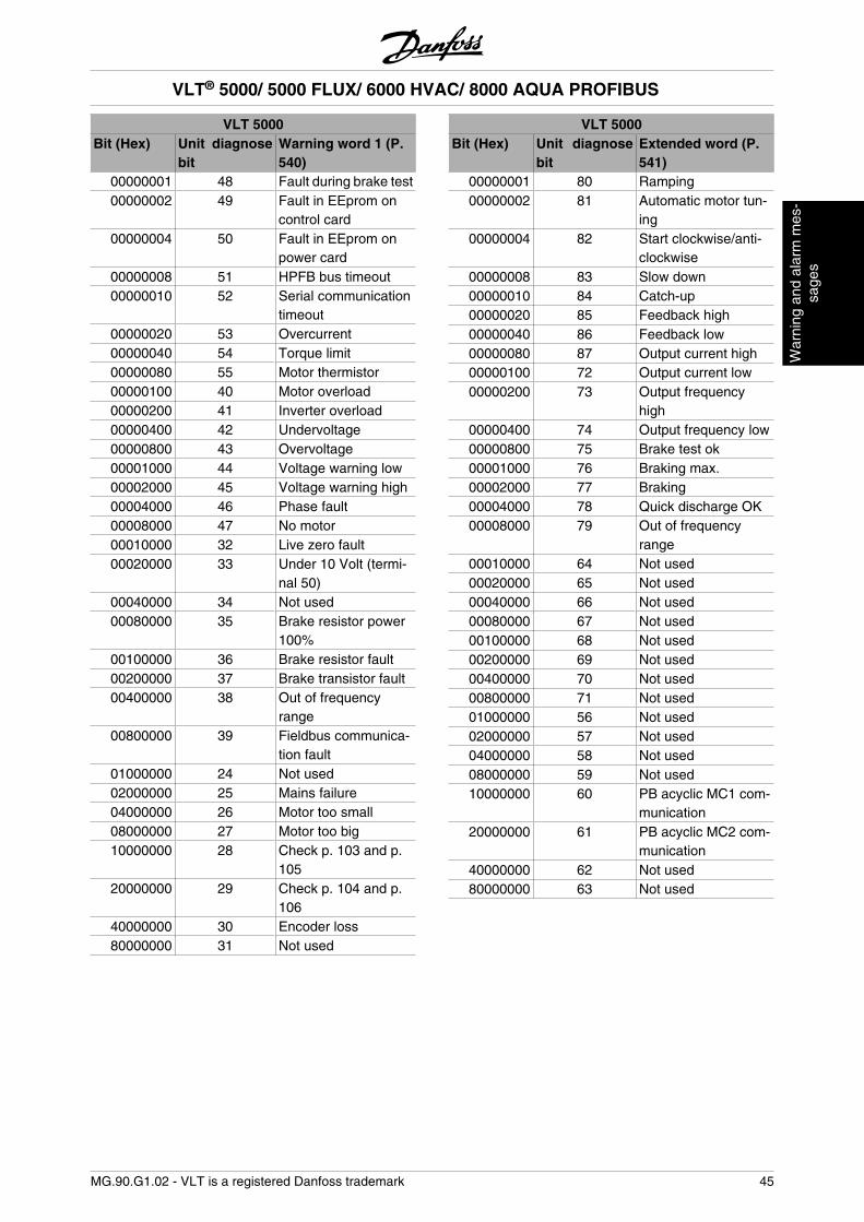
VLT 5000Bit (Hex) Unit diagnose
bitWarning word 1 (P.540)
00000001 48 Fault during brake test00000002 49 Fault in EEprom on
control card00000004 50 Fault in EEprom on
power card00000008 51 HPFB bus timeout00000010 52 Serial communication
timeout00000020 53 Overcurrent00000040 54 Torque limit00000080 55 Motor thermistor00000100 40 Motor overload00000200 41 Inverter overload00000400 42 Undervoltage00000800 43 Overvoltage00001000 44 Voltage warning low00002000 45 Voltage warning high00004000 46 Phase fault00008000 47 No motor00010000 32 Live zero fault00020000 33 Under 10 Volt (termi-
nal 50)00040000 34 Not used00080000 35 Brake resistor power
100%00100000 36 Brake resistor fault00200000 37 Brake transistor fault00400000 38 Out of frequency
range00800000 39 Fieldbus communica-
tion fault01000000 24 Not used02000000 25 Mains failure04000000 26 Motor too small08000000 27 Motor too big10000000 28 Check p. 103 and p.
10520000000 29 Check p. 104 and p.
10640000000 30 Encoder loss80000000 31 Not used
VLT 5000Bit (Hex) Unit diagnose
bitExtended word (P.541)
00000001 80 Ramping00000002 81 Automatic motor tun-
ing00000004 82 Start clockwise/anti-
clockwise00000008 83 Slow down00000010 84 Catch-up00000020 85 Feedback high00000040 86 Feedback low00000080 87 Output current high00000100 72 Output current low00000200 73 Output frequency
high00000400 74 Output frequency low00000800 75 Brake test ok00001000 76 Braking max.00002000 77 Braking00004000 78 Quick discharge OK00008000 79 Out of frequency
range00010000 64 Not used00020000 65 Not used00040000 66 Not used00080000 67 Not used00100000 68 Not used00200000 69 Not used00400000 70 Not used00800000 71 Not used01000000 56 Not used02000000 57 Not used04000000 58 Not used08000000 59 Not used10000000 60 PB acyclic MC1 com-
munication20000000 61 PB acyclic MC2 com-
munication40000000 62 Not used80000000 63 Not used
VLT® 5000/ 5000 FLUX/ 6000 HVAC/ 8000 AQUA PROFIBUS
MG.90.G1.02 - VLT is a registered Danfoss trademark 45
War
ning
and
ala
rm m
es-
sage
s
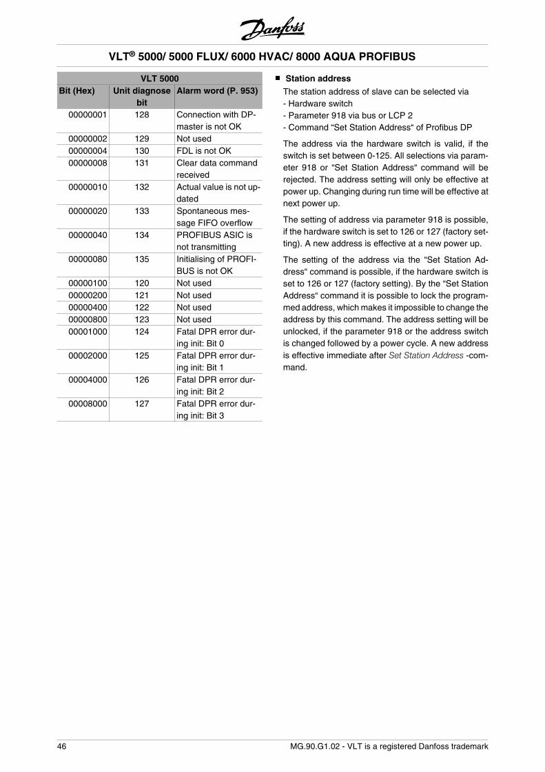
VLT 5000Bit (Hex) Unit diagnose
bitAlarm word (P. 953)
00000001 128 Connection with DP-master is not OK
00000002 129 Not used00000004 130 FDL is not OK00000008 131 Clear data command
received00000010 132 Actual value is not up-
dated00000020 133 Spontaneous mes-
sage FIFO overflow00000040 134 PROFIBUS ASIC is
not transmitting00000080 135 Initialising of PROFI-
BUS is not OK00000100 120 Not used00000200 121 Not used00000400 122 Not used00000800 123 Not used00001000 124 Fatal DPR error dur-
ing init: Bit 000002000 125 Fatal DPR error dur-
ing init: Bit 100004000 126 Fatal DPR error dur-
ing init: Bit 200008000 127 Fatal DPR error dur-
ing init: Bit 3
Station address
The station address of slave can be selected via- Hardware switch- Parameter 918 via bus or LCP 2- Command “Set Station Address“ of Profibus DP
The address via the hardware switch is valid, if theswitch is set between 0-125. All selections via param-eter 918 or “Set Station Address“ command will berejected. The address setting will only be effective atpower up. Changing during run time will be effective atnext power up.
The setting of address via parameter 918 is possible,if the hardware switch is set to 126 or 127 (factory set-ting). A new address is effective at a new power up.
The setting of the address via the “Set Station Ad-dress“ command is possible, if the hardware switch isset to 126 or 127 (factory setting). By the “Set StationAddress“ command it is possible to lock the program-med address, which makes it impossible to change theaddress by this command. The address setting will beunlocked, if the parameter 918 or the address switchis changed followed by a power cycle. A new addressis effective immediate after Set Station Address -com-mand.
VLT® 5000/ 5000 FLUX/ 6000 HVAC/ 8000 AQUA PROFIBUS
46 MG.90.G1.02 - VLT is a registered Danfoss trademark
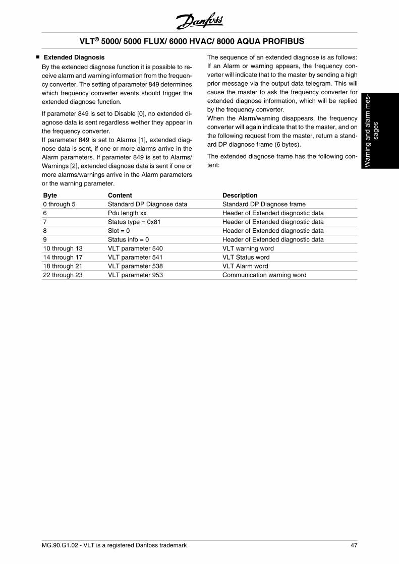
Extended Diagnosis
By the extended diagnose function it is possible to re-ceive alarm and warning information from the frequen-cy converter. The setting of parameter 849 determineswhich frequency converter events should trigger theextended diagnose function.
If parameter 849 is set to Disable [0], no extended di-agnose data is sent regardless wether they appear inthe frequency converter.If parameter 849 is set to Alarms [1], extended diag-nose data is sent, if one or more alarms arrive in theAlarm parameters. If parameter 849 is set to Alarms/Warnings [2], extended diagnose data is sent if one ormore alarms/warnings arrive in the Alarm parametersor the warning parameter.
The sequence of an extended diagnose is as follows:If an Alarm or warning appears, the frequency con-verter will indicate that to the master by sending a highprior message via the output data telegram. This willcause the master to ask the frequency converter forextended diagnose information, which will be repliedby the frequency converter.When the Alarm/warning disappears, the frequencyconverter will again indicate that to the master, and onthe following request from the master, return a stand-ard DP diagnose frame (6 bytes).
The extended diagnose frame has the following con-tent:
Byte Content Description0 through 5 Standard DP Diagnose data Standard DP Diagnose frame6 Pdu length xx Header of Extended diagnostic data7 Status type = 0x81 Header of Extended diagnostic data8 Slot = 0 Header of Extended diagnostic data9 Status info = 0 Header of Extended diagnostic data10 through 13 VLT parameter 540 VLT warning word14 through 17 VLT parameter 541 VLT Status word18 through 21 VLT parameter 538 VLT Alarm word22 through 23 VLT parameter 953 Communication warning word
VLT® 5000/ 5000 FLUX/ 6000 HVAC/ 8000 AQUA PROFIBUS
MG.90.G1.02 - VLT is a registered Danfoss trademark 47
War
ning
and
ala
rm m
es-
sage
s
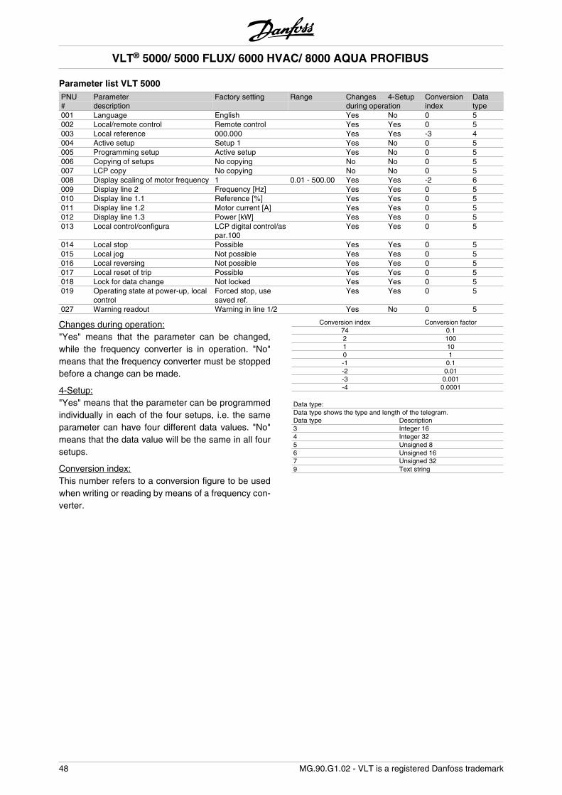
Parameter list VLT 5000PNU Parameter Factory setting Range Changes 4-Setup Conversion Data# description during operation index type001 Language English Yes No 0 5002 Local/remote control Remote control Yes Yes 0 5003 Local reference 000.000 Yes Yes -3 4004 Active setup Setup 1 Yes No 0 5005 Programming setup Active setup Yes No 0 5006 Copying of setups No copying No No 0 5007 LCP copy No copying No No 0 5008 Display scaling of motor frequency 1 0.01 - 500.00 Yes Yes -2 6009 Display line 2 Frequency [Hz] Yes Yes 0 5010 Display line 1.1 Reference [%] Yes Yes 0 5011 Display line 1.2 Motor current [A] Yes Yes 0 5012 Display line 1.3 Power [kW] Yes Yes 0 5013 Local control/configura LCP digital control/as
par.100 Yes Yes 0 5
014 Local stop Possible Yes Yes 0 5015 Local jog Not possible Yes Yes 0 5016 Local reversing Not possible Yes Yes 0 5017 Local reset of trip Possible Yes Yes 0 5018 Lock for data change Not locked Yes Yes 0 5019 Operating state at power-up, local
controlForced stop, usesaved ref.
Yes Yes 0 5
027 Warning readout Warning in line 1/2 Yes No 0 5
Changes during operation:"Yes" means that the parameter can be changed,while the frequency converter is in operation. "No"means that the frequency converter must be stoppedbefore a change can be made.
4-Setup:"Yes" means that the parameter can be programmedindividually in each of the four setups, i.e. the sameparameter can have four different data values. "No"means that the data value will be the same in all foursetups.
Conversion index:This number refers to a conversion figure to be usedwhen writing or reading by means of a frequency con-verter.
Conversion index Conversion factor74 0.12 1001 100 1-1 0.1-2 0.01-3 0.001-4 0.0001
Data type: Data type shows the type and length of the telegram.Data type Description3 Integer 164 Integer 325 Unsigned 86 Unsigned 167 Unsigned 329 Text string
VLT® 5000/ 5000 FLUX/ 6000 HVAC/ 8000 AQUA PROFIBUS
48 MG.90.G1.02 - VLT is a registered Danfoss trademark
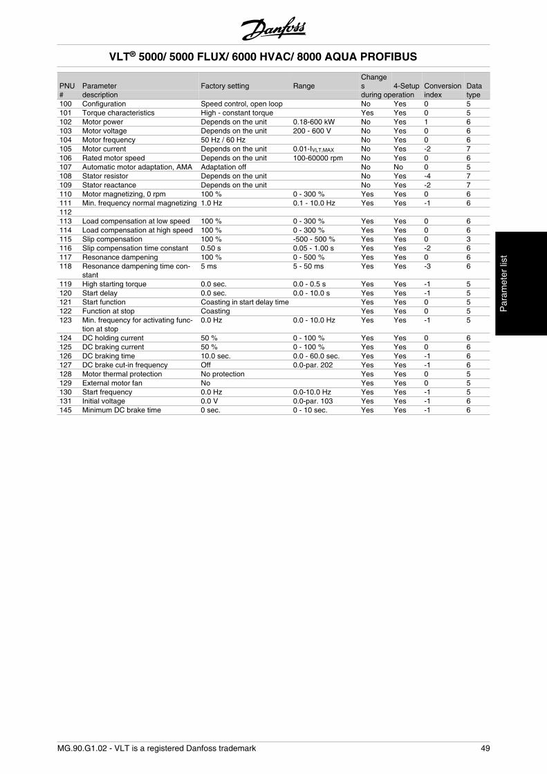
PNU Parameter Factory setting RangeChanges 4-Setup Conversion Data
# description during operation index type100 Configuration Speed control, open loop No Yes 0 5101 Torque characteristics High - constant torque Yes Yes 0 5102 Motor power Depends on the unit 0.18-600 kW No Yes 1 6103 Motor voltage Depends on the unit 200 - 600 V No Yes 0 6104 Motor frequency 50 Hz / 60 Hz No Yes 0 6105 Motor current Depends on the unit 0.01-IVLT,MAX No Yes -2 7106 Rated motor speed Depends on the unit 100-60000 rpm No Yes 0 6107 Automatic motor adaptation, AMA Adaptation off No No 0 5108 Stator resistor Depends on the unit No Yes -4 7109 Stator reactance Depends on the unit No Yes -2 7110 Motor magnetizing, 0 rpm 100 % 0 - 300 % Yes Yes 0 6111 Min. frequency normal magnetizing 1.0 Hz 0.1 - 10.0 Hz Yes Yes -1 6112 113 Load compensation at low speed 100 % 0 - 300 % Yes Yes 0 6114 Load compensation at high speed 100 % 0 - 300 % Yes Yes 0 6115 Slip compensation 100 % -500 - 500 % Yes Yes 0 3116 Slip compensation time constant 0.50 s 0.05 - 1.00 s Yes Yes -2 6117 Resonance dampening 100 % 0 - 500 % Yes Yes 0 6118 Resonance dampening time con-
stant5 ms 5 - 50 ms Yes Yes -3 6
119 High starting torque 0.0 sec. 0.0 - 0.5 s Yes Yes -1 5120 Start delay 0.0 sec. 0.0 - 10.0 s Yes Yes -1 5121 Start function Coasting in start delay time Yes Yes 0 5122 Function at stop Coasting Yes Yes 0 5123 Min. frequency for activating func-
tion at stop0.0 Hz 0.0 - 10.0 Hz Yes Yes -1 5
124 DC holding current 50 % 0 - 100 % Yes Yes 0 6125 DC braking current 50 % 0 - 100 % Yes Yes 0 6126 DC braking time 10.0 sec. 0.0 - 60.0 sec. Yes Yes -1 6127 DC brake cut-in frequency Off 0.0-par. 202 Yes Yes -1 6128 Motor thermal protection No protection Yes Yes 0 5129 External motor fan No Yes Yes 0 5130 Start frequency 0.0 Hz 0.0-10.0 Hz Yes Yes -1 5131 Initial voltage 0.0 V 0.0-par. 103 Yes Yes -1 6145 Minimum DC brake time 0 sec. 0 - 10 sec. Yes Yes -1 6
VLT® 5000/ 5000 FLUX/ 6000 HVAC/ 8000 AQUA PROFIBUS
MG.90.G1.02 - VLT is a registered Danfoss trademark 49
Par
amet
er li
st
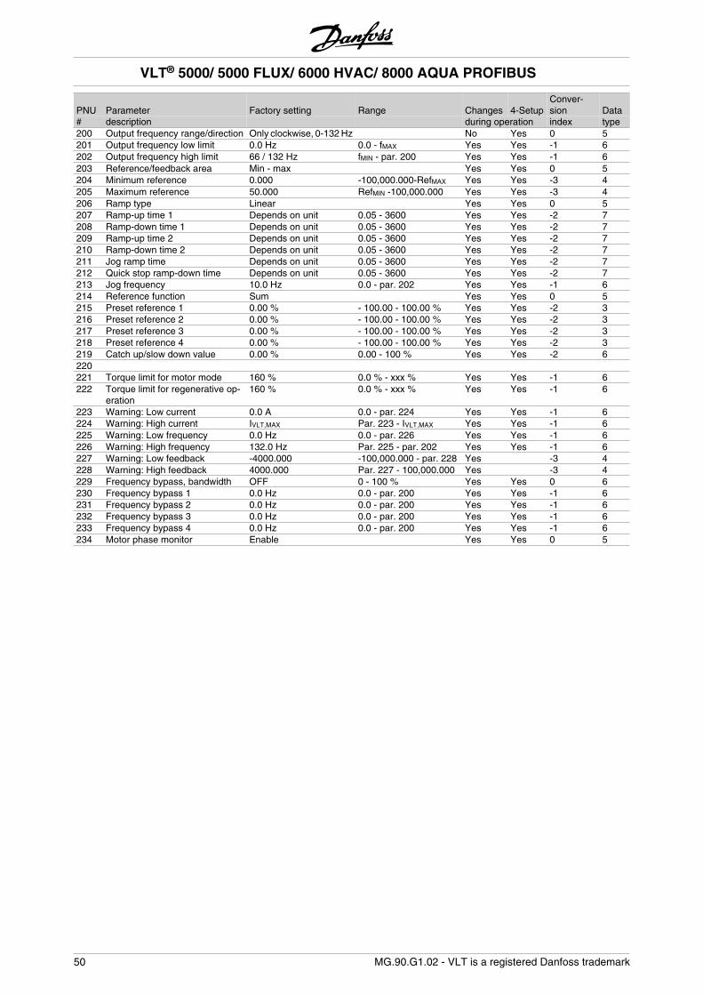
PNU Parameter Factory setting Range Changes 4-SetupConver-sion Data
# description during operation index type200 Output frequency range/direction Only clockwise, 0-132 Hz No Yes 0 5201 Output frequency low limit 0.0 Hz 0.0 - fMAX Yes Yes -1 6202 Output frequency high limit 66 / 132 Hz fMIN - par. 200 Yes Yes -1 6203 Reference/feedback area Min - max Yes Yes 0 5204 Minimum reference 0.000 -100,000.000-RefMAX Yes Yes -3 4205 Maximum reference 50.000 RefMIN -100,000.000 Yes Yes -3 4206 Ramp type Linear Yes Yes 0 5207 Ramp-up time 1 Depends on unit 0.05 - 3600 Yes Yes -2 7208 Ramp-down time 1 Depends on unit 0.05 - 3600 Yes Yes -2 7209 Ramp-up time 2 Depends on unit 0.05 - 3600 Yes Yes -2 7210 Ramp-down time 2 Depends on unit 0.05 - 3600 Yes Yes -2 7211 Jog ramp time Depends on unit 0.05 - 3600 Yes Yes -2 7212 Quick stop ramp-down time Depends on unit 0.05 - 3600 Yes Yes -2 7213 Jog frequency 10.0 Hz 0.0 - par. 202 Yes Yes -1 6214 Reference function Sum Yes Yes 0 5215 Preset reference 1 0.00 % - 100.00 - 100.00 % Yes Yes -2 3216 Preset reference 2 0.00 % - 100.00 - 100.00 % Yes Yes -2 3217 Preset reference 3 0.00 % - 100.00 - 100.00 % Yes Yes -2 3218 Preset reference 4 0.00 % - 100.00 - 100.00 % Yes Yes -2 3219 Catch up/slow down value 0.00 % 0.00 - 100 % Yes Yes -2 6220 221 Torque limit for motor mode 160 % 0.0 % - xxx % Yes Yes -1 6222 Torque limit for regenerative op-
eration160 % 0.0 % - xxx % Yes Yes -1 6
223 Warning: Low current 0.0 A 0.0 - par. 224 Yes Yes -1 6224 Warning: High current IVLT,MAX Par. 223 - IVLT,MAX Yes Yes -1 6225 Warning: Low frequency 0.0 Hz 0.0 - par. 226 Yes Yes -1 6226 Warning: High frequency 132.0 Hz Par. 225 - par. 202 Yes Yes -1 6227 Warning: Low feedback -4000.000 -100,000.000 - par. 228 Yes -3 4228 Warning: High feedback 4000.000 Par. 227 - 100,000.000 Yes -3 4229 Frequency bypass, bandwidth OFF 0 - 100 % Yes Yes 0 6230 Frequency bypass 1 0.0 Hz 0.0 - par. 200 Yes Yes -1 6231 Frequency bypass 2 0.0 Hz 0.0 - par. 200 Yes Yes -1 6232 Frequency bypass 3 0.0 Hz 0.0 - par. 200 Yes Yes -1 6233 Frequency bypass 4 0.0 Hz 0.0 - par. 200 Yes Yes -1 6234 Motor phase monitor Enable Yes Yes 0 5
VLT® 5000/ 5000 FLUX/ 6000 HVAC/ 8000 AQUA PROFIBUS
50 MG.90.G1.02 - VLT is a registered Danfoss trademark
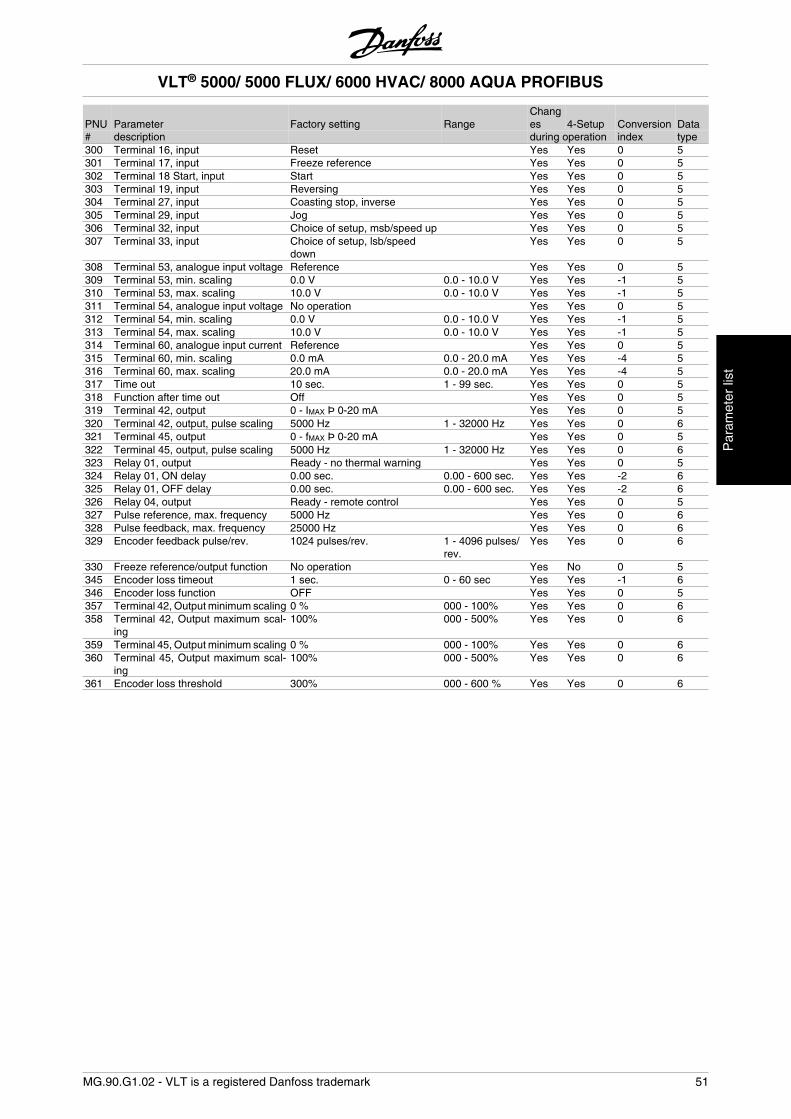
PNU Parameter Factory setting RangeChanges 4-Setup Conversion Data
# description during operation index type300 Terminal 16, input Reset Yes Yes 0 5301 Terminal 17, input Freeze reference Yes Yes 0 5302 Terminal 18 Start, input Start Yes Yes 0 5303 Terminal 19, input Reversing Yes Yes 0 5304 Terminal 27, input Coasting stop, inverse Yes Yes 0 5305 Terminal 29, input Jog Yes Yes 0 5306 Terminal 32, input Choice of setup, msb/speed up Yes Yes 0 5307 Terminal 33, input Choice of setup, lsb/speed
down Yes Yes 0 5
308 Terminal 53, analogue input voltage Reference Yes Yes 0 5309 Terminal 53, min. scaling 0.0 V 0.0 - 10.0 V Yes Yes -1 5310 Terminal 53, max. scaling 10.0 V 0.0 - 10.0 V Yes Yes -1 5311 Terminal 54, analogue input voltage No operation Yes Yes 0 5312 Terminal 54, min. scaling 0.0 V 0.0 - 10.0 V Yes Yes -1 5313 Terminal 54, max. scaling 10.0 V 0.0 - 10.0 V Yes Yes -1 5314 Terminal 60, analogue input current Reference Yes Yes 0 5315 Terminal 60, min. scaling 0.0 mA 0.0 - 20.0 mA Yes Yes -4 5316 Terminal 60, max. scaling 20.0 mA 0.0 - 20.0 mA Yes Yes -4 5317 Time out 10 sec. 1 - 99 sec. Yes Yes 0 5318 Function after time out Off Yes Yes 0 5319 Terminal 42, output 0 - IMAX Þ 0-20 mA Yes Yes 0 5320 Terminal 42, output, pulse scaling 5000 Hz 1 - 32000 Hz Yes Yes 0 6321 Terminal 45, output 0 - fMAX Þ 0-20 mA Yes Yes 0 5322 Terminal 45, output, pulse scaling 5000 Hz 1 - 32000 Hz Yes Yes 0 6323 Relay 01, output Ready - no thermal warning Yes Yes 0 5324 Relay 01, ON delay 0.00 sec. 0.00 - 600 sec. Yes Yes -2 6325 Relay 01, OFF delay 0.00 sec. 0.00 - 600 sec. Yes Yes -2 6326 Relay 04, output Ready - remote control Yes Yes 0 5327 Pulse reference, max. frequency 5000 Hz Yes Yes 0 6328 Pulse feedback, max. frequency 25000 Hz Yes Yes 0 6329 Encoder feedback pulse/rev. 1024 pulses/rev. 1 - 4096 pulses/
rev.Yes Yes 0 6
330 Freeze reference/output function No operation Yes No 0 5345 Encoder loss timeout 1 sec. 0 - 60 sec Yes Yes -1 6346 Encoder loss function OFF Yes Yes 0 5357 Terminal 42, Output minimum scaling 0 % 000 - 100% Yes Yes 0 6358 Terminal 42, Output maximum scal-
ing100% 000 - 500% Yes Yes 0 6
359 Terminal 45, Output minimum scaling 0 % 000 - 100% Yes Yes 0 6360 Terminal 45, Output maximum scal-
ing100% 000 - 500% Yes Yes 0 6
361 Encoder loss threshold 300% 000 - 600 % Yes Yes 0 6
VLT® 5000/ 5000 FLUX/ 6000 HVAC/ 8000 AQUA PROFIBUS
MG.90.G1.02 - VLT is a registered Danfoss trademark 51
Par
amet
er li
st
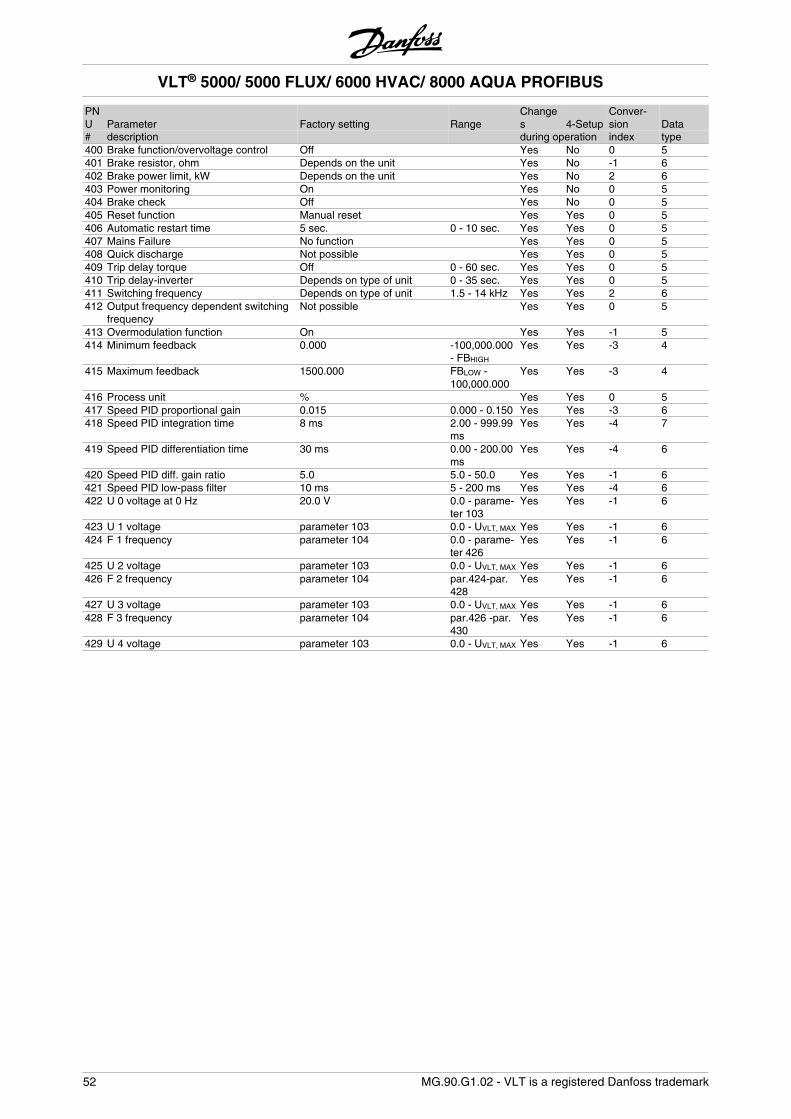
PNU Parameter Factory setting Range
Changes 4-Setup
Conver-sion Data
# description during operation index type400 Brake function/overvoltage control Off Yes No 0 5401 Brake resistor, ohm Depends on the unit Yes No -1 6402 Brake power limit, kW Depends on the unit Yes No 2 6403 Power monitoring On Yes No 0 5404 Brake check Off Yes No 0 5405 Reset function Manual reset Yes Yes 0 5406 Automatic restart time 5 sec. 0 - 10 sec. Yes Yes 0 5407 Mains Failure No function Yes Yes 0 5408 Quick discharge Not possible Yes Yes 0 5409 Trip delay torque Off 0 - 60 sec. Yes Yes 0 5410 Trip delay-inverter Depends on type of unit 0 - 35 sec. Yes Yes 0 5411 Switching frequency Depends on type of unit 1.5 - 14 kHz Yes Yes 2 6412 Output frequency dependent switching
frequencyNot possible Yes Yes 0 5
413 Overmodulation function On Yes Yes -1 5414 Minimum feedback 0.000 -100,000.000
- FBHIGH
Yes Yes -3 4
415 Maximum feedback 1500.000 FBLOW -100,000.000
Yes Yes -3 4
416 Process unit % Yes Yes 0 5417 Speed PID proportional gain 0.015 0.000 - 0.150 Yes Yes -3 6418 Speed PID integration time 8 ms 2.00 - 999.99
msYes Yes -4 7
419 Speed PID differentiation time 30 ms 0.00 - 200.00ms
Yes Yes -4 6
420 Speed PID diff. gain ratio 5.0 5.0 - 50.0 Yes Yes -1 6421 Speed PID low-pass filter 10 ms 5 - 200 ms Yes Yes -4 6422 U 0 voltage at 0 Hz 20.0 V 0.0 - parame-
ter 103Yes Yes -1 6
423 U 1 voltage parameter 103 0.0 - UVLT, MAX Yes Yes -1 6424 F 1 frequency parameter 104 0.0 - parame-
ter 426Yes Yes -1 6
425 U 2 voltage parameter 103 0.0 - UVLT, MAX Yes Yes -1 6426 F 2 frequency parameter 104 par.424-par.
428Yes Yes -1 6
427 U 3 voltage parameter 103 0.0 - UVLT, MAX Yes Yes -1 6428 F 3 frequency parameter 104 par.426 -par.
430Yes Yes -1 6
429 U 4 voltage parameter 103 0.0 - UVLT, MAX Yes Yes -1 6
VLT® 5000/ 5000 FLUX/ 6000 HVAC/ 8000 AQUA PROFIBUS
52 MG.90.G1.02 - VLT is a registered Danfoss trademark
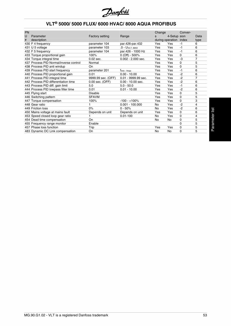
PNU Parameter Factory setting Range
Changes 4-Setup
Conver-sion Data
# description during operation index type430 F 4 frequency parameter 104 par.426-par.432 Yes Yes -1 6431 U 5 voltage parameter 103 .0 - UVLT, MAX Yes Yes -1 6432 F 5 frequency parameter 104 par.426 - 1000 Hz Yes Yes -1 6433 Torque proportional gain 100% 0 (Off) - 500% Yes Yes 0 6434 Torque integral time 0.02 sec. 0.002 - 2.000 sec. Yes Yes -3 7437 Process PID Normal/inverse control Normal Yes Yes 0 5438 Process PID anti windup On Yes Yes 0 5439 Process PID start frequency parameter 201 fmin - fmax Yes Yes -1 6440 Process PID proportional gain 0.01 0.00 - 10.00 Yes Yes -2 6441 Process PID integral time 9999.99 sec. (OFF) 0.01 - 9999.99 sec. Yes Yes -2 7442 Process PID differentiation time 0.00 sec. (OFF) 0.00 - 10.00 sec. Yes Yes -2 6443 Process PID diff. gain limit 5.0 5.0 - 50.0 Yes Yes -1 6444 Process PID lowpass filter time 0.01 0.01 - 10.00 Yes Yes -2 6445 Flying start Disable Yes Yes 0 5446 Switching pattern SFAVM Yes Yes 0 5447 Torque compensation 100% -100 - +100% Yes Yes 0 3448 Gear ratio 1 0.001 - 100.000 No Yes -2 4449 Friction loss 0% 0 - 50% No Yes -2 6450 Mains voltage at mains fault Depends on unit Depends on unit Yes Yes 0 6453 Speed closed loop gear ratio 1 0.01-100 No Yes 0 4454 Dead time compensation On No No 0 5455 Frequency range monitor Enable 0 5457 Phase loss function Trip Yes Yes 0 5483 Dynamic DC Link compensation On No No 0 5
VLT® 5000/ 5000 FLUX/ 6000 HVAC/ 8000 AQUA PROFIBUS
MG.90.G1.02 - VLT is a registered Danfoss trademark 53
Par
amet
er li
st
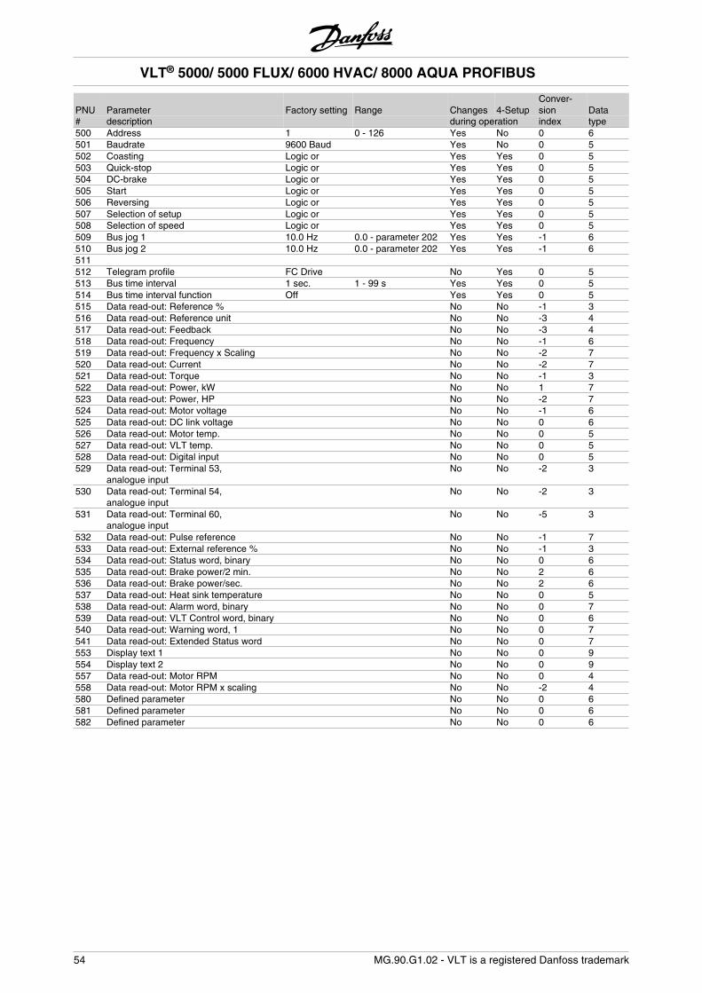
PNU Parameter Factory setting Range Changes 4-SetupConver-sion Data
# description during operation index type500 Address 1 0 - 126 Yes No 0 6501 Baudrate 9600 Baud Yes No 0 5502 Coasting Logic or Yes Yes 0 5503 Quick-stop Logic or Yes Yes 0 5504 DC-brake Logic or Yes Yes 0 5505 Start Logic or Yes Yes 0 5506 Reversing Logic or Yes Yes 0 5507 Selection of setup Logic or Yes Yes 0 5508 Selection of speed Logic or Yes Yes 0 5509 Bus jog 1 10.0 Hz 0.0 - parameter 202 Yes Yes -1 6510 Bus jog 2 10.0 Hz 0.0 - parameter 202 Yes Yes -1 6511 512 Telegram profile FC Drive No Yes 0 5513 Bus time interval 1 sec. 1 - 99 s Yes Yes 0 5514 Bus time interval function Off Yes Yes 0 5515 Data read-out: Reference % No No -1 3516 Data read-out: Reference unit No No -3 4517 Data read-out: Feedback No No -3 4518 Data read-out: Frequency No No -1 6519 Data read-out: Frequency x Scaling No No -2 7520 Data read-out: Current No No -2 7521 Data read-out: Torque No No -1 3522 Data read-out: Power, kW No No 1 7523 Data read-out: Power, HP No No -2 7524 Data read-out: Motor voltage No No -1 6525 Data read-out: DC link voltage No No 0 6526 Data read-out: Motor temp. No No 0 5527 Data read-out: VLT temp. No No 0 5528 Data read-out: Digital input No No 0 5529 Data read-out: Terminal 53,
analogue input No No -2 3
530 Data read-out: Terminal 54,analogue input
No No -2 3
531 Data read-out: Terminal 60,analogue input
No No -5 3
532 Data read-out: Pulse reference No No -1 7533 Data read-out: External reference % No No -1 3534 Data read-out: Status word, binary No No 0 6535 Data read-out: Brake power/2 min. No No 2 6536 Data read-out: Brake power/sec. No No 2 6537 Data read-out: Heat sink temperature No No 0 5538 Data read-out: Alarm word, binary No No 0 7539 Data read-out: VLT Control word, binary No No 0 6540 Data read-out: Warning word, 1 No No 0 7541 Data read-out: Extended Status word No No 0 7553 Display text 1 No No 0 9554 Display text 2 No No 0 9557 Data read-out: Motor RPM No No 0 4558 Data read-out: Motor RPM x scaling No No -2 4580 Defined parameter No No 0 6581 Defined parameter No No 0 6582 Defined parameter No No 0 6
VLT® 5000/ 5000 FLUX/ 6000 HVAC/ 8000 AQUA PROFIBUS
54 MG.90.G1.02 - VLT is a registered Danfoss trademark
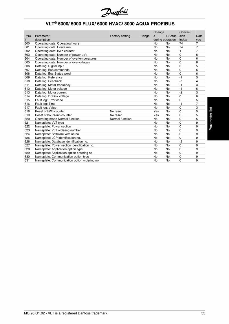
PNU Parameter Factory setting RangeChanges 4-Setup
Conver-sion Data
# description during operation index ype600 Operating data: Operating hours No No 74 7601 Operating data: Hours run No No 74 7602 Operating data: kWh counter No No 1 7603 Operating data: Number of power-up's No No 0 6604 Operating data: Number of overtemperatures No No 0 6605 Operating data: Number of overvoltages No No 0 6606 Data log: Digital input No No 0 5607 Data log: Bus commands No No 0 6608 Data log: Bus Status word No No 0 6609 Data log: Reference No No -1 3610 Data log: Feedback No No -3 4611 Data log: Motor frequency No No -1 3612 Data log: Motor voltage No No -1 6613 Data log: Motor current No No -2 3614 Data log: DC link voltage No No 0 6615 Fault log: Error code No No 0 5616 Fault log: Time No No -1 7617 Fault log: Value No No 0 3618 Reset of kWh counter No reset Yes No 0 5619 Reset of hours-run counter No reset Yes No 0 5620 Operating mode Normal function Normal function No No 0 5621 Nameplate: VLT type No No 0 9622 Nameplate: Power section No No 0 9623 Nameplate: VLT ordering number No No 0 9624 Nameplate: Software version no. No No 0 9625 Nameplate: LCP identification no. No No 0 9626 Nameplate: Database identification no. No No -2 9627 Nameplate: Power section identification no. No No 0 9628 Nameplate: Application option type No No 0 9629 Nameplate: Application option ordering no. No No 0 9630 Nameplate: Communication option type No No 0 9631 Nameplate: Communication option ordering no. No No 0 9
VLT® 5000/ 5000 FLUX/ 6000 HVAC/ 8000 AQUA PROFIBUS
MG.90.G1.02 - VLT is a registered Danfoss trademark 55
Par
amet
er li
st
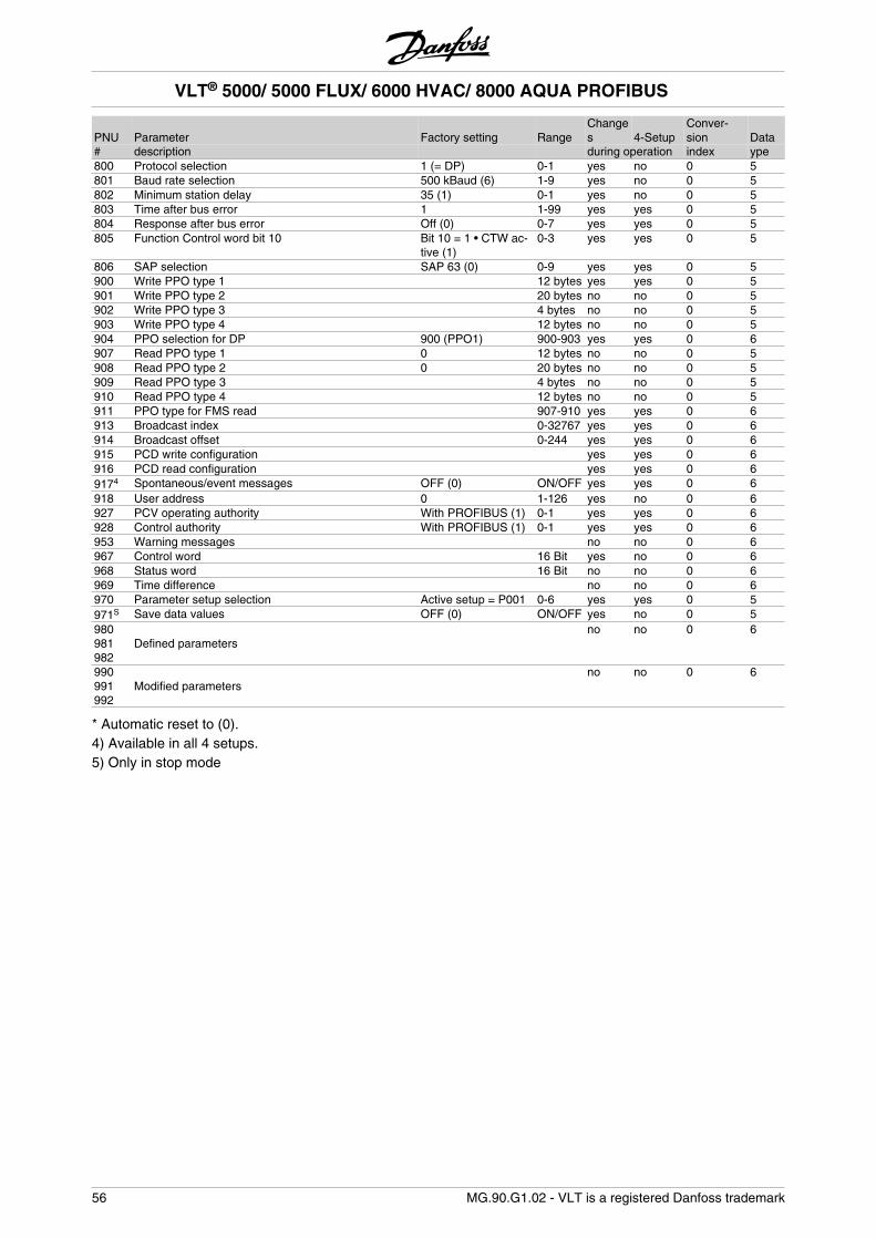
PNU Parameter Factory setting RangeChanges 4-Setup
Conver-sion Data
# description during operation index ype800 Protocol selection 1 (= DP) 0-1 yes no 0 5801 Baud rate selection 500 kBaud (6) 1-9 yes no 0 5802 Minimum station delay 35 (1) 0-1 yes no 0 5803 Time after bus error 1 1-99 yes yes 0 5804 Response after bus error Off (0) 0-7 yes yes 0 5805 Function Control word bit 10 Bit 10 = 1 • CTW ac-
tive (1)0-3 yes yes 0 5
806 SAP selection SAP 63 (0) 0-9 yes yes 0 5900 Write PPO type 1 12 bytes yes yes 0 5901 Write PPO type 2 20 bytes no no 0 5902 Write PPO type 3 4 bytes no no 0 5903 Write PPO type 4 12 bytes no no 0 5904 PPO selection for DP 900 (PPO1) 900-903 yes yes 0 6907 Read PPO type 1 0 12 bytes no no 0 5908 Read PPO type 2 0 20 bytes no no 0 5909 Read PPO type 3 4 bytes no no 0 5910 Read PPO type 4 12 bytes no no 0 5911 PPO type for FMS read 907-910 yes yes 0 6913 Broadcast index 0-32767 yes yes 0 6914 Broadcast offset 0-244 yes yes 0 6915 PCD write configuration yes yes 0 6916 PCD read configuration yes yes 0 69174 Spontaneous/event messages OFF (0) ON/OFF yes yes 0 6918 User address 0 1-126 yes no 0 6927 PCV operating authority With PROFIBUS (1) 0-1 yes yes 0 6928 Control authority With PROFIBUS (1) 0-1 yes yes 0 6953 Warning messages no no 0 6967 Control word 16 Bit yes no 0 6968 Status word 16 Bit no no 0 6969 Time difference no no 0 6970 Parameter setup selection Active setup = P001 0-6 yes yes 0 5971S Save data values OFF (0) ON/OFF yes no 0 5980981982
Defined parameters no no 0 6
990991992
Modified parameters no no 0 6
* Automatic reset to (0).4) Available in all 4 setups.5) Only in stop mode
VLT® 5000/ 5000 FLUX/ 6000 HVAC/ 8000 AQUA PROFIBUS
56 MG.90.G1.02 - VLT is a registered Danfoss trademark
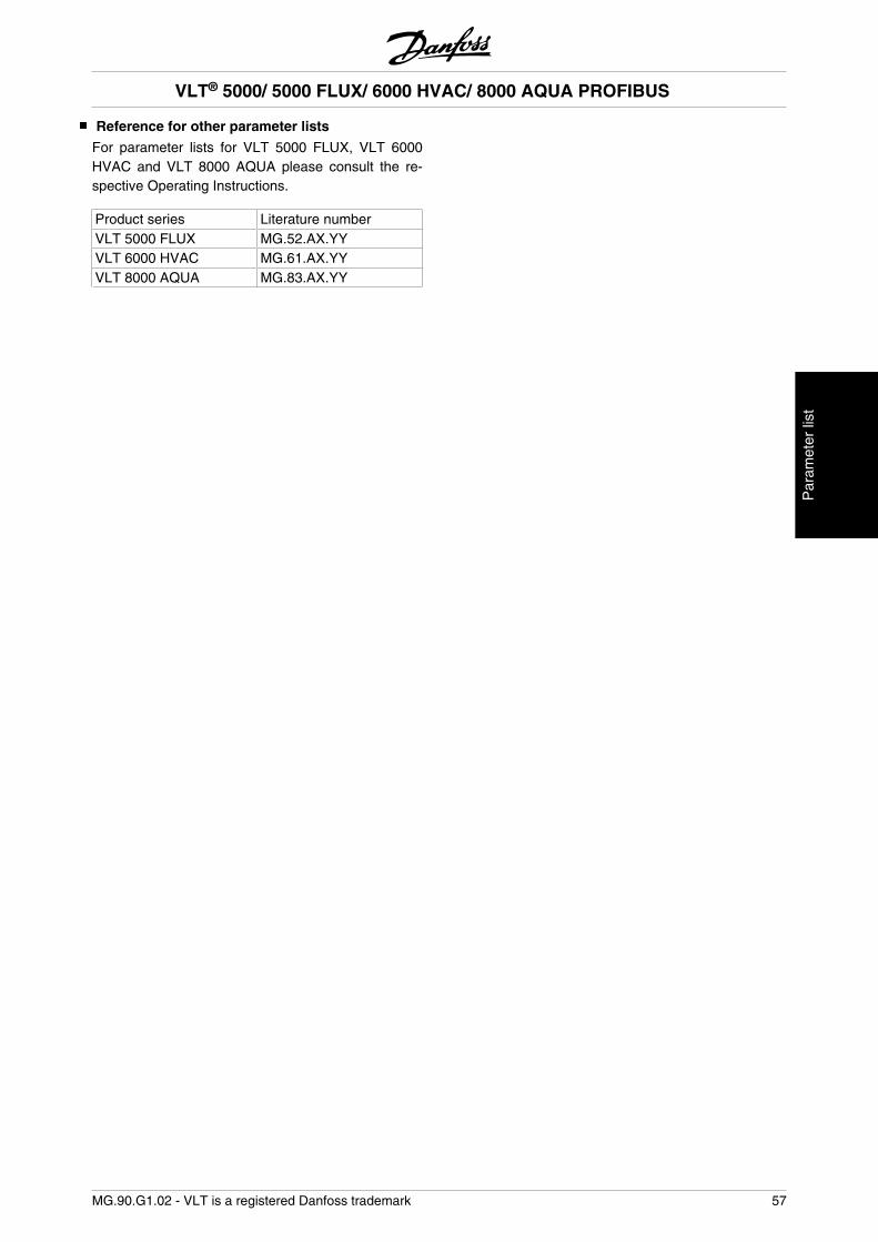
Reference for other parameter lists
For parameter lists for VLT 5000 FLUX, VLT 6000HVAC and VLT 8000 AQUA please consult the re-spective Operating Instructions.
Product series Literature numberVLT 5000 FLUX MG.52.AX.YYVLT 6000 HVAC MG.61.AX.YYVLT 8000 AQUA MG.83.AX.YY
VLT® 5000/ 5000 FLUX/ 6000 HVAC/ 8000 AQUA PROFIBUS
MG.90.G1.02 - VLT is a registered Danfoss trademark 57
Par
amet
er li
st
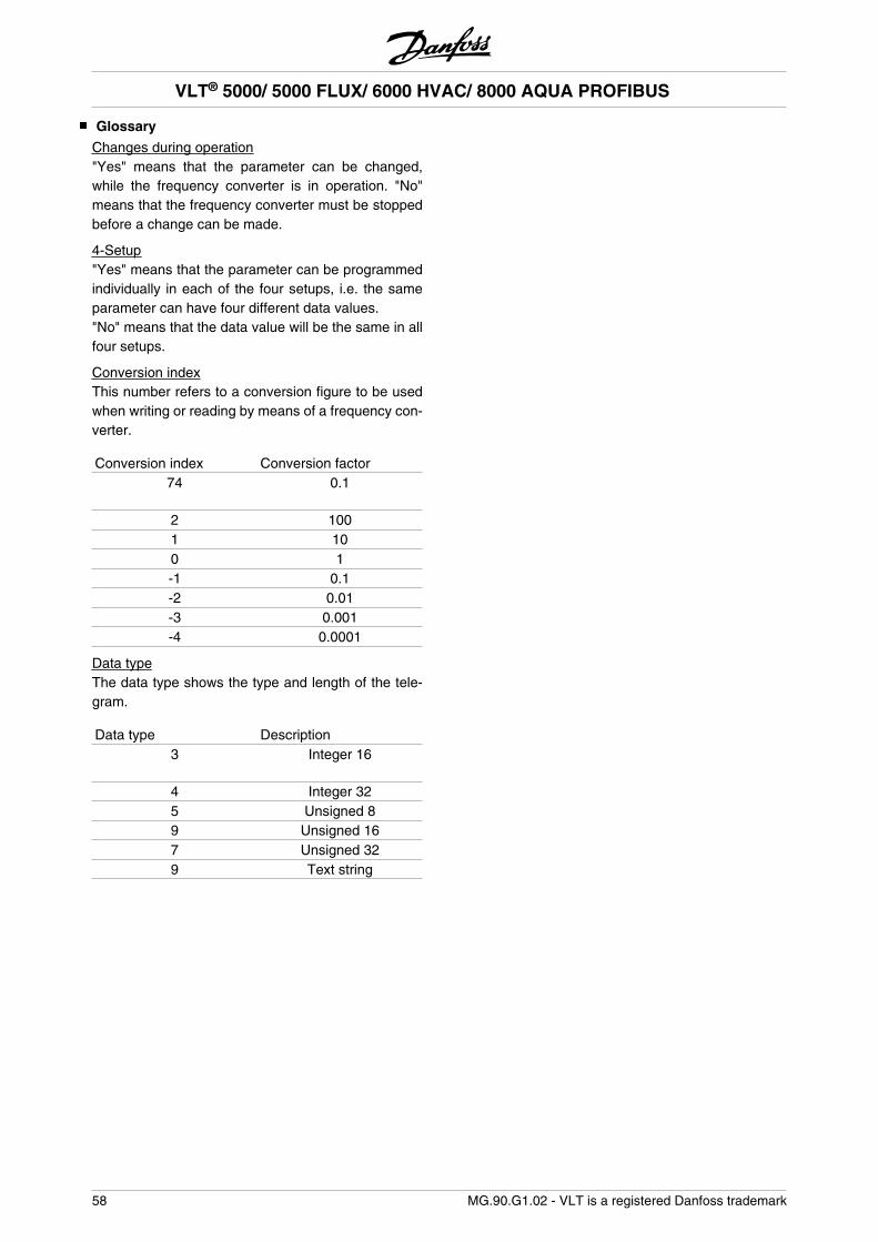
Glossary
Changes during operation"Yes" means that the parameter can be changed,while the frequency converter is in operation. "No"means that the frequency converter must be stoppedbefore a change can be made.
4-Setup"Yes" means that the parameter can be programmedindividually in each of the four setups, i.e. the sameparameter can have four different data values."No" means that the data value will be the same in allfour setups.
Conversion indexThis number refers to a conversion figure to be usedwhen writing or reading by means of a frequency con-verter.
Conversion index Conversion factor74 0.1
2 1001 100 1-1 0.1-2 0.01-3 0.001-4 0.0001
Data typeThe data type shows the type and length of the tele-gram.
Data type Description3 Integer 16
4 Integer 325 Unsigned 89 Unsigned 167 Unsigned 329 Text string
VLT® 5000/ 5000 FLUX/ 6000 HVAC/ 8000 AQUA PROFIBUS
58 MG.90.G1.02 - VLT is a registered Danfoss trademark
Abbreviations used
English German DescriptionALI - Application Layer InterfaceATTR - Connection AttributeCTW STW Control WordDP - Decentralizen PeripheryEIA - Electronic Industries Association: Author of the EIA standard RS 485-AEMC EMV Electromagnetic CompatibilityFIFO - First In First OutFMS - Fieldbus Message SpecificationHd - Hammind DistanceHPFB - High Performance Field BusIND - SubindexI/O E/A Input/OutputISO - International Standards OrganizationLSB - Lowest Significant BitMSB - Most Significant BitMAP - Manufucturing Automation ProtocolMAV HIW Main Actual ValueMMS - Manufucturing Message SpecificationMRV HSW Main Reference ValueOD OV Object DirectoryPC - Personal ComputerPCA PKE Parameter CharacteristicsPCD PZD Process DataPCV PKW Parameter Characteristics ValuePDU - Protocol Data UnitPLC SPS Programmable Logic ControlPNU - Parameter NumberPPO - Parameter Process Data ObjectPVA PWE Parameter ValueRC AK Request/Response CharacteristicsSPM - Spontaneous MessageSTW ZSW Status WordTSDR - Station DelayTRT - Target Rotation TimeVDE - Verein Deutscher ElektrotechnikerVDI - Verein Deutscher Elektroingenieure
VLT® 5000/ 5000 FLUX/ 6000 HVAC/ 8000 AQUA PROFIBUS
MG.90.G1.02 - VLT is a registered Danfoss trademark 59
App
endi
x
Index
AAbbreviations used 59
About this manual 3
Additional display readings 43
Address switches 14
Alarm messages 43
Assumptions 4
BBackground knowledge 4
Bus connection 11
Bus reference value 29
Bus topology 7
CCable connection FCM 300 11
Cable length 9
Cable screening 11
Characteristics 19
Communication connections 17
Communication partners 6
Control word according to FC standard 27
Control word according to Profidrive Profile 24
conversion factor 19
Conversion index 19
Copyrights, 3
CTW 30
Current output frequency 17
Cyclical transmission 7
EEarthing, 11
EMC 11
Example 1: PCV Channel 30
Example 2: Process data from the frequency converter 31
Example 3: Array treatment 32
FFactory settings 48
Fault messages 43
Features of a Master type 1 connection 8
Features of a Master type 2 connection: 8
Features of DP 7
FMS 3
FREEZE 22
Frequency converter response time behaviour 16
GGlossary 58
GSD files 34
LLEDs 13
Limitation of Liability 3
MMaster-controlled frequency converters 6
MAV 31
MRV 30
Nnumber of nodes 9
PParameter 502 5
Parameter 904 5
Parameter 918 5
Parameter description 19
Parametergroups (800 and 900) specific to the PROFIBUS 35
Parameters 3
PCA 30
PCA interface 4
PCA processing 18
PCD 30
physical connection. 3
PPO description 17
Principle of data exchange by Profibus DP V0/DP V1 8
Profibus DP 5
PROFIBUS DP 17
Profibus DP V1 5
Profibus DP V1 8
Profibus FMS, 3
Profibus option card. 3
Protective measures for EMC 11
PVA 30
QQuick start 5
RRC 18
Request and response 18
Revision Rights 3
Sshield connection 11
Single master operation with DP V0 7
Size attribute 19
Spontaneous message 43
Spontaneous messages 21
Spontaneous messages 43
Standardized value 19
Status word according to FC standard 28
Status word according to Profidrive profile 26
STW 31
SYNC 22
TTime behaviour during SYSTEM update 16
UUNFREEZE 22
UNSYNC 22
VVLT frequency converter parameters 35
VLT® 5000/ 5000 FLUX/ 6000 HVAC/ 8000 AQUA PROFIBUS
60 MG.90.G1.02 - VLT is a registered Danfoss trademark
WWARN. 34 43
Warnings: 43
VLT® 5000/ 5000 FLUX/ 6000 HVAC/ 8000 AQUA PROFIBUS
MG.90.G1.02 - VLT is a registered Danfoss trademark 61
Inde
x