
RollerDriveCNCTM - Sankyo Automation · unclamp time and requires no energy like conventional...
24
The Zero-Backlash CNC Rotary Table Precision. Quality. Reliability. RollerDrive CNC TM AUTOMATION
Transcript of RollerDriveCNCTM - Sankyo Automation · unclamp time and requires no energy like conventional...
The Zero-Backlash CNC Rotary Table
Precision. Quality. Reliability.
RollerDrive CNCTM
AUTOMATION

The Zero-Backlash CNC Rotary TableRollerDrive CNCTM
2
The answer for a CNC rotary axis
Pure Motion By Zero-Backlash Technology
No Clamp Operation
Perpetual Precision
RollerDrive motion
Actual motion with distortion pronedrives
Dis
plac
emen
t D
ispl
acem
ent
Time
Time
CNCRollerDrive TM
The RollerDrive CNC, a CNC rotary table, is designed to fulfill the demands of the latest machine tools for increased speed and precision. Inside, the RollerDrive CNC uses a RollerDrive, our zero-backlash reducer which transmits motion without distortions while staying robust against external forces unlike existing gears and torque motors. The high precision and rigidity achieved by the zero-backlash technology gives the RollerDrive CNC a rotational accuracy of less than ±10 arc sec. and repeatability of less than ±4 arc sec., and remains robust while doing heavy cutting work on hard metals.
The RollerDrive CNC does not require a clamp operation due to its mechanically rigid zero-backlash structure. This eliminates clamp and unclamp time and requires no energy like conventional hydraulic/air systems. Combined, the distortion-free performance and no-clamp design delivers ultra fast positioning that leads to higher productivity. For instance, a typical 90-degree rotation can be done within 0.4 seconds.
The unique mechanism of the RollerDrive makes the RollerDrive CNC capable of withstanding years of operation without internal part wear or loss of precision. Regular calibration or readjustment work is unnecessary for the RollerDrive CNC.
Overview
3
RollerDrive CNCTM
Mechanism
Output angle
0 90 180 270 360-0.02
-0.01
0.01
0
CNC
Typical worm gear rotary table
Output angle
Err
orE
rror
0 90 180 270 360-0.02
-0.01
0.01
0
RollerDrive
CW
CW
CCW
CCW
Approved Performance
Performance By Zero-Backlash Technology
Be Distinctive
by Sankyo Automation
TM
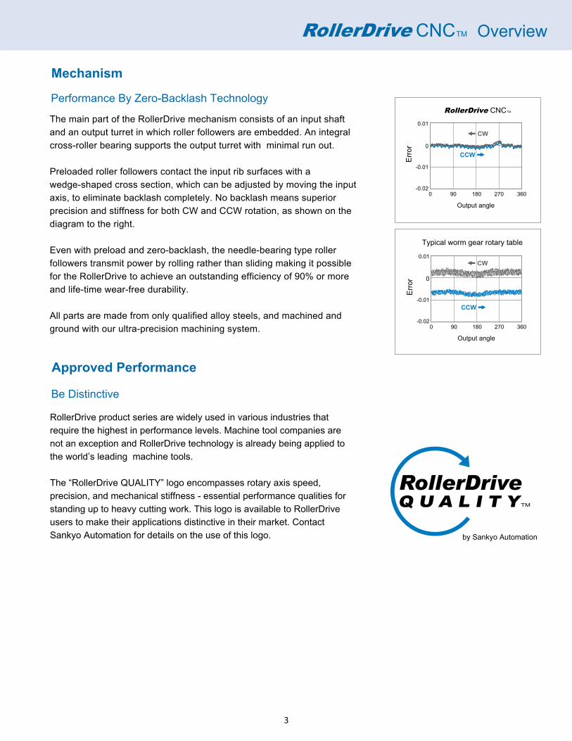
The main part of the RollerDrive mechanism consists of an input shaft and an output turret in which roller followers are embedded. An integral cross-roller bearing supports the output turret with minimal run out.
Preloaded roller followers contact the input rib surfaces with a wedge-shaped cross section, which can be adjusted by moving the input axis, to eliminate backlash completely. No backlash means superior precision and stiffness for both CW and CCW rotation, as shown on the diagram to the right.
Even with preload and zero-backlash, the needle-bearing type roller followers transmit power by rolling rather than sliding making it possible for the RollerDrive to achieve an outstanding efficiency of 90% or more and life-time wear-free durability.
All parts are made from only qualified alloy steels, and machined and ground with our ultra-precision machining system.
RollerDrive product series are widely used in various industries that require the highest in performance levels. Machine tool companies are not an exception and RollerDrive technology is already being applied to the world’s leading machine tools.
The “RollerDrive QUALITY” logo encompasses rotary axis speed, precision, and mechanical stiffness - essential performance qualities for standing up to heavy cutting work. This logo is available to RollerDrive users to make their applications distinctive in their market. Contact Sankyo Automation for details on the use of this logo.

4
Overview
Exclusive Zero Backlash Structure
Roller followers Roller gear cam (input)
Turret(output)
Features• No backlash• Power transferred by rolling contact eliminates wear• High accuracy and good efficiency• Preloadable for high rigidity
Rolling contact Preload
Stud
Outerraceway
Roller gearcam surface
Needles
Preload Mechanism Internal Construction of the Roller Follower
• Worm gear modelsMaintenance costs occur once or twice a year to adjust the backlash.
• RollerDriveLong-term use is possible without any mechanical maintenance.Beats the cost of a worm gear even after adding annual running costs to the initial investment cost. Price performance continues thereafter.
Cost Comparison Versus Worm Gear Rotary TableOffers Long-term Use Low Maintenance
$20,000
$10,000
01 2 3 4 5 6 7 Year
Cost simulations are based on a table diameter of about 200 mm.
Initial Cost versus Annual Maintenance Costs
Worm gearrotary table
Roller drive
Cost becomes less than theworm gear table in three years.
• Worm gear modelsAccuracy declines over time. Requires maintenance to achieve initial accuracy.
• The RollerDriveAccuracy is consistent with no maintenance even after 5 million operation cycles. (Requires regular oil changes)
Consistent long-term accuracy without need forbacklash adjustment.
30
20
10
00 1 Million 2 Million 3 Million 4 Million 5 Million
Operating cycles
Positioning Accuracy Aging Test
High
Low
Positioning E
rror
The RollerDrive graph is based on internal testing.
(arc sec)
Maintenance
Maintenance
Worm gear rotary t
able (example)
RollerDrive
Requiresmaintenanceat regularintervals
Drop in accuracy overtime
Consistent long-termaccuracy withoutmaintenance.
Based on internal calculations.
Low Maintenance and Excellent Price Performance
① Worm gear rotary tables require maintenance twice a year.② Assumes an annual running cost of 3% (oil changes, etc.) for both types.

5
Servo Motor
Preload + Rolling contact achieveszero-backlash and long life
Outstanding rotating accuracy and rigiditywith the integrated cross roller bearing
Shock resistant, high-performancecam followers
Overview
Model Line Up & Applications
6
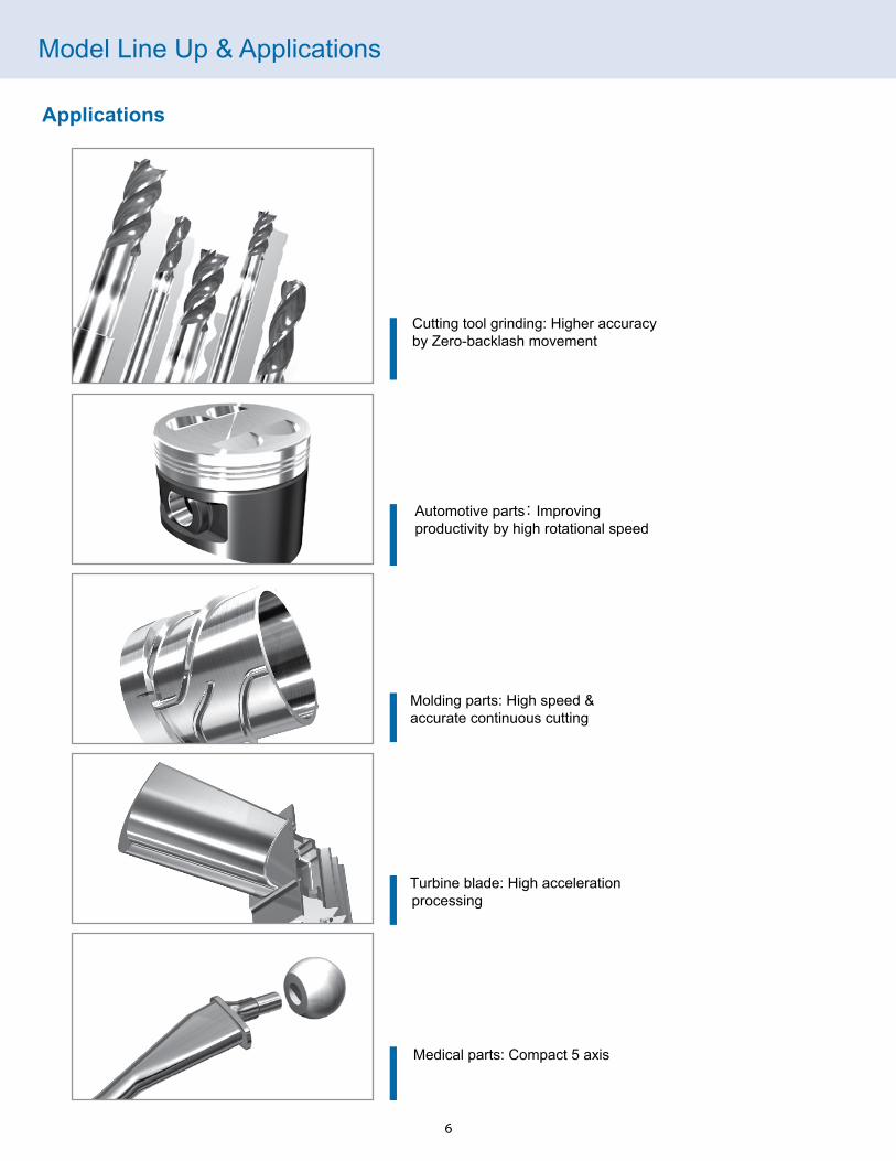
Cutting tool grinding: Higher accuracyby Zero-backlash movement
Automotive parts: Improvingproductivity by high rotational speed
Molding parts: High speed &accurate continuous cutting
Medical parts: Compact 5 axis
Turbine blade: High accelerationprocessing
Applications
Model Line Up & Applications
7
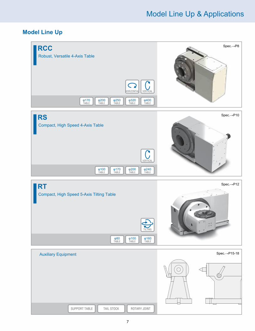
Model Line Up
RCCRobust, Versatile 4-Axis Table
Spec.→P8
VERTICALHORIZONTAL
TABLEφ400
TABLEφ320
TABLEφ250
RSCompact, High Speed 4-Axis Table
Spec.→P10
VERTICAL
TABLEφ240
TABLEφ200
TABLEφ170
TABLEφ100
RTCompact, High Speed 5-Axis Tilting Table
Spec.→P12
TILTING
TABLEφ100
TABLEφ80
Auxiliary Equipment Spec.→P15-18
SUPPORT TABLE ROTARY JOINTTAIL STOCK
TABLEφ200
TABLEφ170
TABLEφ160
RCC Specifications
8
1
RCC170RCC200RCC250RCC320RCC400
ABCX
RL
SB
1(See Dimensions
diagrams)
E CJ (Built-in)H (External)
RCC2001
L -- 2C
3B
41
5E
6C
7J
8
Model
2
Servo motormounting side
3
Servo Motor
4
Connector Encoder Hydraulic ClampOption
Rotary joint
5 6 7 8
Table
2. Servo motor mounting side
R
L
3. Servo Motor
A
Manufacture
FANUC
MITSUBISHI
SANYO
B
C
D
X
E
Ask Sankyo for mounting other motors
4. Connector
S
B
Model Code
SpecificationsTable diameter mm
mm
mm
arc.sec
rpm
arc.sec
Table reference bore diameter
Center height
Maximum table speed
Repeatability
Net weight
Gear ratio
RCC170φ170
φ65 H7150
75
870
1/60
RCC200φ200
φ75 H7165
75
4100
1/60
Indexing accuracy ±15 ±10
Loading Characteristics
Allowable payload
Maximum output torque
Continuous holding torque
Allowable bending moment
Allowable axial load
Upright position
Allowable inertia moment
Allowable load
Horizontal position
kg
N
N・mN・m
N・m
kg・m2
RCC170
16012740
168
287
598
80kg
RCC200
20015789
286
524
948
100
1.0 1.2
kg
Options
Output rotary encoder
External rotary joint (number of ports)
Hydraulic clamper torque (N•m/6Mpa)
RCC170
66+1
RON/RCN200(HEIDENHAIN)
350
Built-in rotary joint (number of ports)
RCC200
66+1
450
RON/RCN200(HEIDENHAIN)
* These specifications are for reference purposes only, please contact Sankyo for detailed specifications.Contact Sankyo if you wish to use a different motor. Maximum output torque should not exceed 10 seconds or 20% duty cycle.
Depends on which motor is mounted.※1
※2
※2
※2
※1, ※2
RCC250φ250
φ110 H7210
75
4170
1/60
±10
RCC320φ320
φ165 H7255
50
4280
1/60
±10
RCC400φ400
φ200 H7300
50
4410
1/60
±10
RCC250
25037420
528
1003
2210
120
2
RCC320
35056000
768
1481
3550
180
4.5
RCC400
50074220
1368
2675
8135
250
10
RCC250
46+1
990
RON/RCN200(HEIDENHAIN)
RCC320
46+1
1200
RON/RCN200(HEIDENHAIN)
RCC400
46+1
2600
RON/RCN200(HEIDENHAIN)
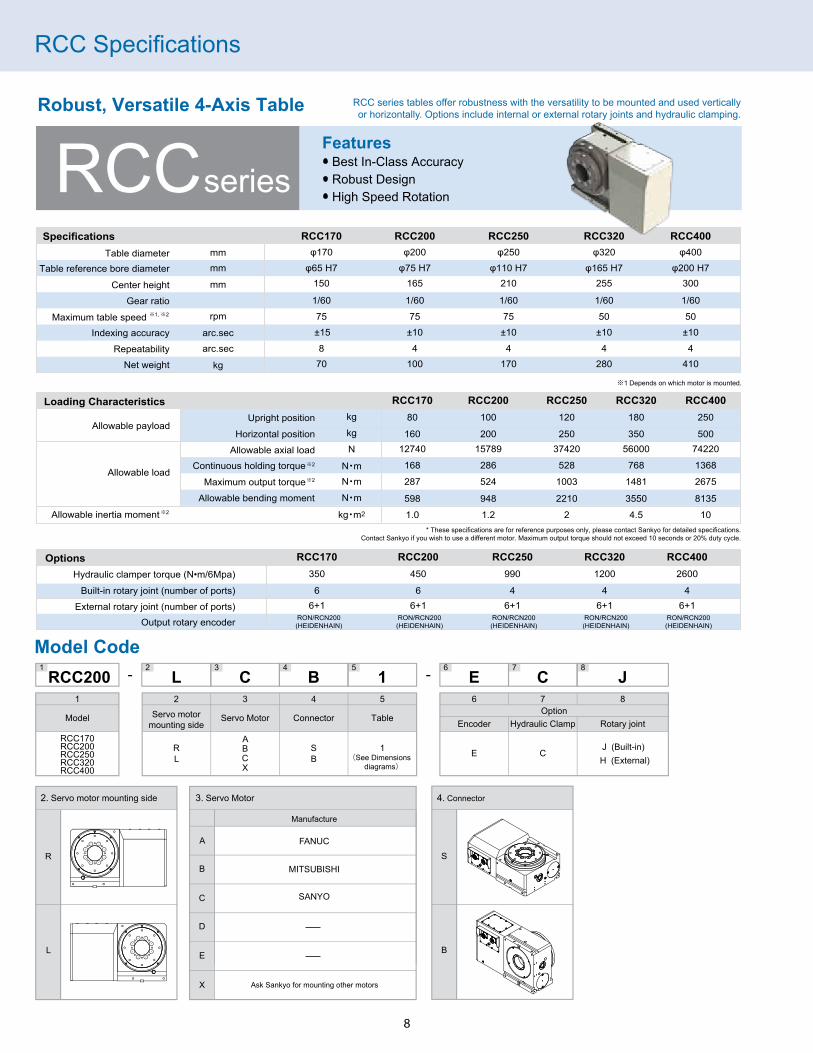
Robust, Versatile 4-Axis Table
RCCseriesFeatures・ Best In-Class Accuracy・ Robust Design・ High Speed Rotation
RCC series tables offer robustness with the versatility to be mounted and used verticallyor horizontally. Options include internal or external rotary joints and hydraulic clamping.

RCC Dimensions
9
RCC170
RCC200
RCC250
RCC320
RCC400
Connector code S Connector code B Table center bore18
217825 30
φ85
φ65H
7
(φ6
6)
φ65H
8265
150
25
1010
2520
20 25
5169180
φ170
203100
430
(8)M5, 8DP
(8)M8, 16DP
Air purge outlet(Reverse side)
(8)M8, 16DP
φ150φ100
20
2025
1012
169180
φ170
Connector code S Connector code B Table center bore192180.5
φ200
2010
1025
20 25
φ75H
7
(φ7
6)
30 35 φ85
φ75H
8
190 2(8)M5, 10DP
20
474242
120
285
2516
523
(8)M10, 20DP(8)M8, 16DP
Air purge outlet(Reverse side)
φ100
φ172
φ200
180.5192 17
1019
2520
Connector code S Connector code B Table center bore
25 30
25 30
1515
15
24
215203290
145
355
3021
0
φ250
597
(8)M10, 20DPAir purge outlet(Reverse side)
20φ110
H7
34 (φ1
26)
φ138
φ125
H8
1214(6)M6, 12DPφ150
21 15
2530
21215203
φ250
Connector code S Connector code B Table center bore
15
25 30
25 30
15
15
37
360
φ320
180
660
3025
544
0
235220
Air purge outlet(Reverse side)
(8)M12, 24DP
φ 195 1234
φ165
H7 25
φ165
H8
φ180
φ166
39
(6)M8, 16DP
1515
2530
φ320
22235220
Connector code S Connector code B Table center bore
210420
794
300
510 φ400
280240
30 40
30 40
5
1818
15
(8)M16, 232DP
Air purge outlet(Reverse side)
φ 240
φ220
φ200
H7
(φ2
01)
53
φ200
H8
279 1
30
(6)M10, 20DP
3040
18 18
22240
280
φ400

RS Specifications
10
Model Code
Servo Motor Motor mounting side Connector
1
RS100RS170RS200RS240
ABCDEX
RL
SB E J
OptionsBuilt-in rotary joint (number of ports)
Output rotary encoder
RS100
4
MPI-536A(MPRZ-536A)(MITSUBISHI)
RS170
5
MPI-536A(MPRZ-536A)(MITSUBISHI)
RS200
5
MPI-536A(MPRZ-536A)(MITSUBISHI)
RS240
5
MPI-536A(MPRZ-536A)(MITSUBISHI)
RS1701
A- -2L
3S
4E
5J
6
Model
2
Servo Motor
3
Motor mounting side
4
Connector Encoder Rotary joint (built-in)
Option5 6
A
Manufacture
FANUC
MITSUBISHI
YASKAWA
SANYO
-
B
C
D
X
E
Ask Sankyo for mounting other motors
R
L
S
B
* If the unit is mounted with an encoder, hydraulic clamp, or rotary joint, the hollow bore table is not available.
SpecificationsTable diameter mm
mm
mm
arc.sec
rpm
arc.sec
kg
Table reference bore diameter
Center height
Maximum table speedIndexing accuracy
RepeatabilityNet. weight
Gear ratio
RS100φ100
φ50 H7125
75±158
38
1/60
RS170φ170
φ80 H7115
75±158
44
1/60
Loading characteristicsAllowable payload
* Maximum holding torque
Continuous holding torque
Allowable bending moment
Allowable axial loadUpright position
Maximum moment of inertia
kg
N
N・mN・m
N・m
kg・m2
* These specifications are for reference purposes only, please contact Sankyo for detailed specifications. Maximum output torque should not exceed 10 seconds or 20% duty cycle.
Allowable load
RS100
6016148
267
290
0.50
40
RS200
10670286
437
1250
1.20
100
RS240
11580404
631
1591
2.00
120
RS240φ240
φ130 H7132
55±104
72
1/90
RS200φ200
φ100 H7125
75±104
56
1/60
RS170
9083168
287
900
0.60
80
Compact 4-Axis Table
RSseriesFeatures・ Oversized bore・ Low profile; compact size・ High-speed rotation
RS Series tables offer a combination of compactness with high torque.Used for many applications from small tapping centers to machining centers.

RS Dimensions
11
RS100 RS170
RS200 RS240
(8)M6, 12DP
145
140
φ100
346
200
125
20
80
85
(8)M8, 16DP
25
215
115
100
386
130
(8)M8, 16DP
φ200
155
160
110
413
25
125
235
160
(8)M12, 22DP
180
140460
φ240
257
132
25
205
210
φ170
150
145
0.5159.5
30
φ80
φ85
φ100
H7
14H7
5
202020
2515 5
14H7 1020
202525
14H7
5
153025
1020
φ130H7
φ120
14H7
5
2020
2525
φ43H
8
34111
529.5
φ25
φ50H
7
0.5149.5
30
φ75
φ70
φ80H
7φ1
30H
7
φ120
φ121
H8
39
199 6
20

RT Specifications
12
Model Code
Servo Motor Motor mounting side Connector
1
RT080RT100RT160
ABCDEX
RL
SB E J
RT1001
A- -2L
3S
4E
5J
6
Model
2
Servo Motor
3
Motor mounting side
4
Connector Encoder Rotary joint (built-in)
Option5 6
A
Manufacture
FANUC
MITSUBISHI
YASKAWA
SANYO
-
B
C
D
X
E
Ask Sankyo for mounting other motors
R
L
S
B
* If the unit is mounted with an encoder, hydraulic clamp, or rotary joint, the hollow bore table is not available.
Specifications
Table diameter
Tilting angle deg
mm
mm
mm
mm
arc.sec
rpm
arc.sec
kg
Table reference bore diameter
Center height at 90 degree
Table surface height at 90 degree
Maximum speed
Indexing accuracy Rotary axisTilt axis
Repeatability
Net. weight
Gear ratio
RT080-20~+120
φ80
φ30 H7
1151/48
6350±20±1588
1/60
70
165
RT100-20~+120
φ100
φ40 H7
1321/48
10075 (55)
±15±1084
1/60 (1/90)
91
197
Options
Built-in rotary joint (number of ports)
Output rotary encoder
RT080
-
-
RT100/RT160
2
MPI-536A(MPRZ-536A)(MITSUBISHI)
-MPI-736A(MPRZ-736B)
(MITSUBISHI)
Loading characteristics
Allowable payload
RT080
3760
10
62
127
141
0.01
RT100
6016
30
118
213
290
0.10
Maximum output torque
Continuous holding torque
Allowable bending moment
Allowable axial load
Allowable inertia moment
kg
N
N・m
N・m
N・m
kg・m2
* These specifications are for reference purposes only, please contact Sankyo for detailed specifications. Maximum output torque should not exceed 10 seconds or 20% duty cycle.
Rotary axisTilt axis
Rotary axisTilt axis
Rotary axis Tilt axis
Allowable load
Rotary axis Tilt axis
Compact 5-Axis Tilting Rotary Table
RTseriesFeatures・ Unique open-end design for small footprint・ High-speed rotation
RT Series tables are perfect for contouring due to zero-backlash technology. The open-end design coupledwith speed and accuracy is suited for many applications from tapping centers to machining centers.
RT160-20~+120
φ160
φ70 H7
1701/48
10050±15±1084
1/72
220
245
RT160
8762
60
172
380
858
0.40

RT Dimensions
13
RT080 RT100
RT160
(With motor on right) (With motor on right)
9043
φ186
φ80
2025
2010
(6)M5, 8DP
53
8514
545
328
R59.550
26
25
115
165
100
386
221
20°120°
14H7
5
0.5
89.5
8.5
φ30H7
Max workpiece dia.100 mm
φ26 +0.1−0.1
φ27
Max workpiece dia.230 mm
120
φ100
φ230
25
2020
0.5
119.
5
1815
φ40H8
φ40H7
Max workpiece dia.170 mm
φ41
125.
5
88.5
180
378
R80 84
(8)M6, 12DP
112.5
2525
140
19725
7
460
132
20°120°
18H7
5
10 5
2525
RT100

Product Specifications
14
Top Motor Mount CNC Rotary Table
167 170
19220043.5221.5
393
200
550
φ252
83
365
200
170 200370
φ252
75.5 189.5359.5
DXB25 TS250
*1. The allowable payload assumes the use of support TS250.
Specifications
Table diameter mm
mm
arc.sec
min−1
arc.sec
kg
Center height
Maximum table speed
Indexing accuracy
Repeatability
Net. weight
Gear ratio
DXB25
φ252
200
40
±10
4
1/80
220
kg
kgm2
Allowable payload
Allowable inertia moment
300
8.5
NmHydraulic clamper
Built-in rotary joint (# of ports)
1200
8 + 1
Output rotary encoder MPRZ-736B
TS250
φ252
200
40
140
8 + 1
Support Table

Auxiliary Equipment
15
Mounting Accessories
Specifications
Series Size
170
200
250
320
400
100
170
200
240
80
100
160
Mounting Type
e
f
c
c
d
a
b
b
b
b
b
b
Qty. Used
2
4
4
4
4
2
4
4
4
4
4
4
RS
RCC
RT
Dimensions for Each Type
abcdf type e type
F
A
D
B
C
E
F
C
D
E
BA
* T-nut and hex bolts not included
G
H
G
14 drill
14 drill
14 drill
18 drill
18 drill
18 drill
DimensionsMounting Type
a
b
c
d
e
f
A
30
30
30
35
25
35
B
35
40
50
66
40
40
C
15
15
20
26
15
15
D
45
45
45
57
55
53
E
35
35
30
39
44.5
38
F G
15
15
15
20
15
19
H
-
-
-
-
20
-

Auxiliary Equipment
16
Support Table
Dimension Drawings
Tailstock
TM115
TM125
TM132
TM150
TM165
TM210
TM255
TM300
115
125
132
150
165
210
255
300
A
115
125
132
150
165
210
255
300
B
270
270
270
352
352
352
352
398
C
115
115
115
180
180
160
160
220
D
85
85
85
105
105
105
105
135
E
32
32
32
44
44
44
44
46
G
180
180
180
270
270
270
270
295
H
18
21
21
33
33
33
33
43
J
14
14
14
14
18
18
18
18
M
MT#2
MT#2
MT#2
MT#3
MT#3
MT#3
MT#3
MT#4
F
φ100
φ100
φ100
φ100
φ100
φ100
φ100
φ150
RS170
RS240
RCC170
RCC200
RCC250
RCC320
RCC400
RS100,RS200
Model(Tentative)
Center height Applicablemodel
Size
M
F
H
E
DB
G
A
JC
100
170
200
240
RS
125
115
125
132
SS110
SS110
SS110
SS110
15
5
15
22
SS150
SS210
150mm
210mm
Center height
450N・m
1700N・m
Clamping torque
16.4(19.3)kg
57.5(62.5)kg
Product weight
Model Code Example for RCC SeriesSS150-C-H165 (For the RCC200 with clamp)SS150-H150 (For the RCC170)
150
235
220250
3464
φ66H
7φ1
50h7
φ60
φ55H
7φ7
0
13
38
φ162
10
115
44
14h7
φ100
Clamping torque 450Nm/6Mpa
(8)M6, 12DP
4-φ14
(4)M6, 12DP
Dimensions with clamp Dimensions in ( ) are without clamp
(105)
(φ60
H7)
(φ80
)
RC1/4Hydraulic inlet
R 7
φ120
18h7
24
150
64
φ100
φ115
H7
φ170
φ110
H7
8015110
345
330300
φ250
210
φ150
50
12H7
19
20
8 Clamping torque 1700Nm/6Mpa
(8)M10, 20DP
4-φ14
(6)M6, 12DP
T-slot details +10
φ150
φ21 5
170
200
250
320
400
RCC
150mm
165mm
210mm
255mm
300mm
SS150
SS150
SS210
SS210
SS210
15mm
30mm
20mm
65mm
110mm
Series Size Center heightSupport spindleWithout clamp
Spacerthickness [mm]
SS110 110mm 10 kg
SS150
SS210
SS110
3415
64φ
120
φ45
φ40
104
308
110
25
65
180
210
14
5
4-14
8-M6
R62.5 100

Auxiliary Equipment
17
Rotary Joints
RCC
RS
RT
666664555−22
Actuation fluid:Hydraulic pressure 6 MPa
Actuation fluid:Air 0.7 MPa
External
Built-In
Specifications
Size
Maximum actuation pressure
Built-In External
Max number of ports
Model
* 1 The +1 indicates the port that in the center bore.
* 2 Make sure to furnish a line filter in the air supply line.
* 3 Under prolonged used, a small amount of actuation oil may leak from an oil port toward the adjacent air port. If possible, the adjacent ports should be left open for use as drain ports.
17020025032040010017020024080100160
6+16+16+16+16+1−−−−−−−
ABC D
EF
GOutport
Rc1/4Inport
A
B
EC
FD
VIEW A
200
A
Mounting hole dimensions
φ8.2
1.4±0.05
φ4
60°
Outport
40
6-Rc1/4Inport
E
RCC250, 320, 400
Mounting hole dimensions
Outport
ABC
D EFGH
I
Rc1/4Inport
ABC
DE
F
GH
I
48-55
E
φ12.
2
φ6
1.4±0.05
RCC170, 200
RCC170 - RCC400

Auxiliary Equipment
18
Compatible Servomotor ModelsModel FANUC
RCC series
RS series
RT series
RCC170
RCC200
RCC250
RCC320
RCC400
RS100
RS170
RS200
RS240
αiF2/5000
αiF4/5000
αiF8/3000
αiF12/3000
αiF22/3000
αis2/5000
αis2/5000
αis4/5000
αis4/5000
βis1/6000
βis1/6000
αis2/5000
αis4/5000
αis4/5000
αis8/4000
MITSUBISHI
HF105BS
HF104BS
HF154BS
HF204BS
HF303BS
HF-KP43JW04-S6
HF-KP43JW04-S6
HF-KP73JW04-S6
HF-KP73JW04-S6
HF-KP43JW04-S6
HF-KP43BJW04-S6
HF-KP43JW04-S6
HF-KP73BJW04-S6
HF-KP73JW04-S6
HF154BS-A48
YASKAWA
SGMAH-04A2A2S
SGMAH-04A2A2S
SGMAH-08A4A2S
SGMAH-08A4A2S
SGMAH-04A2A2S
SGMAH-08A4A2D
SGMAH-08A4A2SJ
SGMAH-08A4A2D
SANYO
R2AA08075FCP
R2AAB8100FCP
R2AA08040FCP
R2AA08040FCP
R2AAB8075FCP
R2AAB8100FCP
R2AA06040FXP
R2AA08075FCP
R2AAB8075HXP
R2AAB8100FCP
OKUMA
BL-ME24J-50SB
BL-ME40J-40SB
BL-ME80J-40SB
BL-ME120J-40SB
BL-ME200J-30SB
RT080
RT100
RT160
Rotary axis
Tilt axis
Rotary axis
Tilt axis
Rotary axis
Tilt axis
Rotary Joints
Built-InRT100
11.25 °
φ50
+0.0
25 0
φ40
+0.0
25 0
φ41
15
50
22
3.5 66.5
φ64
2-Rc1/8
� �
1.4 ± 0.05
φ10
.2+0
.05
0
11.25 °11.25 °
Built-InRS100, 170, 200, 240
Figure applies to models RS100 & RS240.The RS170 and RS200 have a different shape at d and f.
g
c
a fb e
d
h
10+0.05 0φ1
2.2+
0.05
0
1.4 ± 0.05
Model aφ50 +0.025/- 0φ80 +0.03/- 0φ80 +0.03/- 0φ80 +0.03/- 0
bφ24
φ30
φ30
φ30
RS100
RS170
RS200
RS240
c90°
72°
72°
72°
d e12
-
-
26
φ70
φ80
φ80
φ80
fφ90
-
-
φ184
g90°
72°
72°
72°
h4-Rc1/4
5-Rc1/4
5-Rc1/4
5-Rc1/4
Size (mm)

Accuracy Specifications
19
RCC & RSNo. Measurement Method RS100 RCC320 RCC400
RS170RCC170
RS200RCC200
RS240RCC250
1
2
3
4
5
6
7
8
9
Straightness of table top
Runout of table top
Runout of table reference bore
Indexing accuracy
Repeatability
Perpendicularity betweentable top and reference
surface for upright mounting
Parallelism between rotary axisand guide blocks for reference
surface for upright mounting
Deviation between rotary axisand guide blocks for reference
surface for upright mounting
Parallelism between rotatingcenter and reference surface
for upright mounting
0.015mm
0.01mm
0.01mm
±15arc.sec
8arc.sec
0.02mm
0.02mm /150mm
0.02mm /150mm
0.02mm(must not lean forward)
0.015mm
0.01mm
0.01mm
±15arc.sec
8arc.sec
0.02mm
0.02mm /150mm
0.02mm /150mm
0.02mm(must not lean forward)
0.015mm
0.01mm
0.01mm
±10arc.sec
4arc.sec
0.02mm
0.02mm /150mm
0.02mm /150mm
0.02mm(must not lean forward)
0.02mm
0.01mm
0.01mm
±10arc.sec
4arc.sec
0.02mm
0.02mm
0.02mm
0.02mm(must not lean forward)
0.02mm
0.01mm
0.01mm
±10arc.sec
4arc.sec
0.02mm
0.02mm
0.02mm
0.02mm(must not lean forward)
0.02mm
0.01mm
0.01mm
±10arc.sec
4arc.sec
0.02mm
0.02mm
0.02mm
0.02mm(must not lean forward)
RTNo. Measurement Method RT080 RT100
1
2
3
4
5
6
7
8
Straightness of table top
Parallelism between table top andbottom surface of base
Runout of table top
Runout of table reference bore
Indexingaccuracy
Repeatability
Rotary axis
Rotary axis
Tilt axis
Tilt axis
Parallelism between tilt axis center lineand bottom surface of base
Perpendicularity between tabletop and guide block
0.01mmover full length
0.02mmover full length
0.01mm
0.01mm
0.01mm
8arc.sec
0.02mm
8arc.sec
±15arc.sec
±20arc.sec
0.01mmover full length
0.02mmover full length
0.01mm
0.01mm
0.01mm
8arc.sec
0.02mm
4arc.sec
±10arc.sec
±15arc.secIndexingaccuracy
Repeatability
RT160
0.01mmover full length
0.02mmover full length
0.01mm
0.01mm
0.01mm
8arc.sec
0.02mm
4arc.sec
±10arc.sec
±15arc.sec

Technical Information
20
This indicates the percent of input power which is transmitted to the output. The motion mechanism has high efficiency because it employs rolling contact. Efficiency varies depending on conditions such as load torque, rotation speed and temperature.
In the , all rotating elements operate in a state of rolling contact, and thus there is almost no wear, or degradation in accuracy over time.
There is almost no change in positioning accuracy after testing operation (5) million times, and this shows that the outstanding accuracy of the can be maintained over the long term.
EfficiencyRCC250
Effi
cien
cy[%]
Torque[N・m]
02000 400
5 rpm
Output rotation speed
10 rpm20 rpm50 rpm
10
20
30
40
50
60
70
80
90
100
DurabilityTest of changes in RollerDrive positioning accuracy over timeRollerDrive ®
Exactness, forward direction(CCW)
Exactness, reverse direction(CW)
Repeat accuracy, forward direction(CCW)
Repeat accuracy, reverse direction(CW)
0
10
20
30
Out
put p
ositi
onin
g ac
cura
cy[ar
c. s
ec.]
Number of operations (Times)
Test Conditions
RollerDrive size
Output load weight
Output load moment of inertia
Output rotation angle
Output maximum rotation speed
Acceleration time
Constant speed time
Deceleration time
RCC250 class test machine
152 kg(φ500mm)
4.69 kg・m2
0-345 degree(Reciprocating)
100rpm
0.100 sec
0.475 sec.
0.100 sec.
RollerDrive®
0 620,000 1,320,000 1,500,000 2,000,000 2,700,000 3,000,000 4,000,000 5,000,000
RollerDrive®
RollerDrive®

Technical Information
21
Backlash, Lost Motion & Hysteresis Loss
General Hysteresis Graph
Rated torque
Rated torque
Lost motion
Torque acting on output
Tors
ion
angl
e
Torque acting on output [N•m]
Tors
ion
angl
e [ra
d.]
y
Backlash
Hysteresis loss
−3% +3% 50%
−0.0003−100 −50 0 50 100
0.0003
−0.0002
0.0002
−0.0001
0.0001
0.0000
Hysteresis GraphRollerDrive ®
x
Backlash Rotation angle which can arise even with zero torque (looseness)Lost motion Torsion angle of the midpoint of the hysteresis curve width which arises when applying ±3% rated torqueHysteresis loss Torsion angle where there is no complete return, when torque is applied in both forward and reverse directions
RCC250
−+
RollerDrive ®
For a general reducer, the hysteresis graph can be obtained by applying torque to the output shaft, and plotting the generated torsion angle.
Backlash, lost motion and hysteresis loss can each be defined from the hysteresis graph, as indicated above.
Lost motion and hysteresis loss depend on the material characteristics, and occur in all types of structures. Backlash, on the other hand, occurs only when there are gaps or looseness in the structure. Backlash has a major effect on accuracy, servo gain and similar factors, and must be minimized.
With , backlash is completely eliminated using our unique preload structure, and lost motion and hysteresis loss are controlled to extremely small values due to the results of research on optimizing materials and structures.

22
Precautions
General Precautions
Notes On Air Supply
Lubrication
Grinding Machine Applications
Maximum Rotation Speed
OU
T
IN
AC20C-01CG(SMC)(Pressure Gauge G36-2-01)
Air combination
Sankyo's CNC Circular Table comes standard equipped with an air purge outlet. (Use it to blow out condensation and coolant to prolong the life of electrical parts and prevent rust in the motor housing.) Supply clean air for the air purge by referring to the drawing shown to the right.(Do NOT block the exhaust outlet.)
Sankyo's CNC Circular Table uses an oil bath to protect the internal mechanisms and maintain reliability. Refill and perform oil changes regularly using the oil listed in the instruction manual.
When used in grinding machines, the seal device on the outer periphery of our table may become damaged. The warranty does not cover any such damage.
The maximum rotation speed for he table given in the specifications refers to the indexing speed. Consult with Sankyo if the table is to be rotated continuously. Otherwise, the table will generate heat and could lose accuracy. This could also cause overload alarms with the servomotor.
Under the United States trade regulation, RollerDrive CNC can be restricted to supply or export to a country which may produce weapons or related products.
Dimensions and specifications are subjected to be modified without notice.
Contents of this catalogue were published in 2015.
Whole or part of the contents, mechanisms, logos, drawings belong to Sankyo Automation. No part of the catalog is allowed to copy or redistributed to the third party without the written permission of Sankyo Automation.

23
Service Network
Global OfficesSANKYO AUTOMATION10655 State Route 47, Sidney, Ohio 45365 U.S.A.Phone: (937) 498-4901 • Fax: (937) 498-9403E-mail: [email protected]: http://www.sankyoautomation.com
Group CompaniesSANKYO SEISAKUSHO CO., LTD3-37-3 Tabatashinmachi, Kita-ku,Tokyo, Japan 114-8538Phone: +81-3-3800-3330 • Fax: +81-3-3800-3380E-mail: [email protected]: http://www.sankyo-seisokusho.co.jp
Branch OfficeSHENZHENRm 721, Shenzhen Kerry Centre,2008 Renminnan Road, Shenzhen 518001 ChinaPhone: +86-755-8230-0270 • Fax: +86-755-8236-4605E-mail: [email protected]
Branch OfficeTIANJINRm 2706, Golden Building, 20 Nanjing Road,Hexi District Tianjin 300041 ChinaPhone: +86-22-2312-1005 • Fax: +86-22-2312-1007
SANKYO CHINA TRADING CO., LTD.(Shanghai Head Office)Room 1103, Block B, No.391 Guiping Road,Shanghai 200233 ChinaPhone: +86-21-5445-2813 ・ Fax : +86-21-5445-2340E-mail: [email protected]: http://www.sankyochina-trading.com/
SANKYO SEISAKUSHO CO. KOREA443-734103-1105, Digital Empire 2, 486 Shin-dong, Youngtong-gu, Suwon-si, Kyeonggi-do, South Korea Phone: +82 31 (695) 5801 ・ Fax : +82 31 (695) 5803
HANGZHOU SANKYO MACHINERY CO., LTD.No.8 Da Di Road, Xiao Shan Economic and TechnologyDevelopment Zone, Hangzhou Zhe Jiang 311215 China Phone: +82 -571-8283-3311 ・ Fax : +86-571-8283-1133
SANKYO SEISAKUSHO CO. TAIWANNo.25, Gongyequ 40th Rd., Xiehe Vil., Xitun Dist., Taichung City 40768, Taiwan (R.O.C.)Phone: +886-4-2359-4048 • Fax: +886-4-2359-4720
SANKYO CHINA TRADING CO., LTD. SANKYO AUTOMATION
KOREA
TAIWAN
ITALY
SINGAPOREAGENT
OFFICE
SANKYO SEISAKUSHO CO.
SANKYO INTERNATIONALLIMITEDHANGZHOU SANKYO
MACHINERY CO., LTD
THAILAND

10655 State Route 47Sidney, Ohio 45365Phone: (937) 498-4901www.sankyoautomation.com
Represented by:
SAI-CNC-2016/01
AUTOMATION
Specifications and dimensions are subject to change without notice. Consult Sankyo sales before ordering.Patent rights and copyrights for some mechanisms, trademarks, images, drawings and other material in this catalog all belong to Sankyo Seisakusho Co.“RollerDrive” is a registered trademark of Sankyo Seisakusho Co.
Sankyo America Inc. D.B.A. Sankyo Automation.


![HB06MA0012E - Maintenance Manual - Quick Turn Smart … · Select the [TURRET UNCLAMP] menu item in manual operation mode to unclamp the tu rret. Highlight the menu item. TAIL THRUST](https://static.fdocuments.us/doc/165x107/5ad647337f8b9a5c638e20e8/hb06ma0012e-maintenance-manual-quick-turn-smart-the-turret-unclamp-menu.jpg)