Rod Lock Air Cylinders - All Air · Rod Lock Air Cylinders Catalog HY08-0931-1/NA May, ... through...
36
Series 2AJ & 2ANJ Rod Lock Air Cylinders Catalog HY08-0931-1/NA May, 2007
Transcript of Rod Lock Air Cylinders - All Air · Rod Lock Air Cylinders Catalog HY08-0931-1/NA May, ... through...

Series 2AJ & 2ANJRod Lock Air Cylinders
Catalog HY08-0931-1/NAMay, 2007

Parker Hannifin CorporationCylinder DivisionDes Plaines, Illinois USAwww.parker.com/cylinder
Catalog HY08-0931-1/NAFeatures, Benefits, Value
Air CylindersSeries 2AJ & 2ANJ Rod Lock
Rod Lock Features• True Bolt-on Modularity – the cylinder is built and tested as a stand
alone unit. The Rod Lock is then assembled and tested at rated holding force.
• Large Rod Lock Clamping Surface – provides uniform force to the rod contact area. This allows holding forces to resist 100 psi input on the cylinder cap end for most bore and rod combinations.
• Spring-engaged, air-released operation – ensures positive holding in power-off situations with minimal air volume required for release.
• Manual release is standard – cam operated release disengages the Rod Lock with a simple turn of a hex bolt. The default-to-lock function springs back to the engaged position when released.
• Rod Lock is sealed to withstand harsh environments – NEMA 4X rating protects internal components from contamination
Manual override shaft allows release of the Rod Lock independent of pneumatic controls. The override is spring loaded and engages the rod lock when the wrench is removed and the air signal is absent.
Air port for Rod Lock release.
Breather port.
Piston rod extension and Rod Lock pilot conform to NFPA dimensions. Fluorocarbon rod wiper cleans
rod on retract stroke and excludes contamination from the Rod Lock.
Light weight aluminum Rod Lock body is anodized for corrosion protection.
Series 2A or 2AN heavy-duty pneumatic cylinder.
Benefits of using a piston Rod Lock include:• Prevents rod movement upon release of stored energy• Eliminates the need for pilot operated check valves for load holding• Eliminates complicated piping between pilot operated check valves and the cylinder

Catalog HY08-0931-1/NA
1 Parker Hannifin CorporationCylinder DivisionDes Plaines, Illinois USAwww.parker.com/cylinder
Air CylindersSeries 2AJ & 2ANJ Rod Lock
Offer of SaleThe items described in this document are hereby offered for sale by Parker Hannifin Corporation, its subsidiaries or its authorized distributors. This offer and its acceptance are governed by provisions stated on a separate page of the document entitled ‘Offer of Sale’.
WarningFAILURE OR IMPROPER SELECTION OR IMPROPER USE OF THE PRODUCTS AND/OR SYSTEMS DESCRIBED HEREIN OR RELATED ITEMS CAN CAUSE DEATH, PERSONAL INJURY AND PROPERTY DAMAGE.
This document and other information from Parker Hannifin Corporation, its subsidiaries and authorized distributors provide product and/or system options for further investigation by users having technical expertise. It is important that you analyze all aspects of your application, including consequences of any failure and review the information concerning the product or system in the current product catalog. Due to the variety of operating conditions and applications for these products or systems, the user, through its own analysis and testing, is solely responsible for making the final selection of the products and systems and assuring that all performance, safety and warning requirements of the application are met.
The product described herein, including without limitation, product features, specifications, designs, availability and pricing, are subject to change by Parker Hannifin Corporation and its subsidiaries at any time without notice.
Table of Contents Page No.Features, Benefits, Value ...........................................................................................................Inside Front CoverHow to Select a Cylinder ..........................................................................................................................................2Theoretical Output ....................................................................................................................................................2Rod Lock Rated Holding Force ...............................................................................................................................2Mounting Styles / Standard Specifications .............................................................................................................3Model Code ..............................................................................................................................................................4Rod Lock Specifications / Rod Lock Features ........................................................................................................5Connection of Rod Lock, Cylinder and Valve .........................................................................................................5Weight of Cylinder with Rod Lock ...........................................................................................................................6Cylinder Stroke Chart ...............................................................................................................................................7 Stop Tubing / Mounting Classes .............................................................................................................................8T Mount Dimensions ............................................................................................................................................. 10TB, TC, TD Mount Dimensions ............................................................................................................................ 11J Mount Dimensions ............................................................................................................................................. 12H Mount Dimensions ............................................................................................................................................. 13C Mount Dimensions ............................................................................................................................................. 14F Mount Dimensions ............................................................................................................................................. 15BB Mount Dimensions .......................................................................................................................................... 16SB Mount Dimensions .......................................................................................................................................... 17D Mount Dimensions ............................................................................................................................................. 18DB Mount Dimensions .......................................................................................................................................... 19DD Mount Dimensions .......................................................................................................................................... 20Double Rod End Dimensions ............................................................................................................................... 21Style 55 Rod End Dimensions .............................................................................................................................. 22Flange Coupler and Weld Plate Dimensions and Part Numbers ....................................................................... 22Mounting Accessories for Style SB ...................................................................................................................... 23Mounting Accessories – Sizing & Dimensions for All Other Styles ...............................................................24-25Rod Lock Removal and Reinstallation / Torque Values ...................................................................................... 26Service Parts Identification / Service Kits ............................................................................................................. 27Cylinder Safety Guide ......................................................................................................................................28-29Offer of Sale........................................................................................................................................................... 32
Table of Contents

Air CylindersSeries 2AJ & 2ANJ Rod Lock
Catalog HY08-0931-1/NA
2 Parker Hannifin CorporationCylinder DivisionDes Plaines, Illinois USAwww.parker.com/cylinder
How to Select / Push & Pull Forces
How to Select a Series 2AJ or 2ANJ CylinderStep 1 – Determine the correct cylinder bore size necessary to achieve required push or pull force
using the available operating pressure (up to 100 psi). Follow steps in Theoretical Push and Pull Forces below.
Step 2 – Select the mounting style that fits your installation needs. Determine the bore and rod sizes available for the required mounting style and complete the model selection.
Step 3 – Choose a rod end style and the desired rod end accessories.
Theoretical Push and Pull ForcesThe cylinder output forces are derived from this formula:
F = P x A
Where F = Force in pounds. P = Pressure at the cylinder in pounds per square inch. A = Effective area of cylinder piston in square inches.
To determine the bore size for the application, follow the steps below.
1. Select the Operating Pressure column closest to that desired.
2. In the same column, identify the force required to move the load (always rounding up). If the piston rod is in compression use the ‘Push’ row and if the piston rod is in tension use the ‘Pull’ row.
3. In the row to the left is the bore required. To select the correct rod diameter for the stroke required use the Piston Rod-Stroke Selection Chart on page 7.
If the cylinder envelope dimensions are too large for the application, increase the operating pressure to the maximum pressure in the table below, if possible, and repeat steps 1 - 3.
Push and Pull Force in Pounds
60 80 100 60 80 100Push 1.767 106 141 177 Push 19.635 1178 1571 1964Pull 1.460 88 117 146 Pull 18.850 1131 1508 1885
Push 3.142 189 251 314 Push 19.635 1178 1571 1964Pull 2.835 170 227 284 Pull 18.150 1089 1452 1815
Push 3.142 189 251 – Push 19.635 1178 1571 –Pull 2.357 141 189 – Pull 17.230 1034 1378 –
Push 4.909 295 393 491 Push 28.274 1696 2262 2830Pull 4.602 276 368 460 Pull 26.789 1607 2143 2679
Push 4.909 295 393 491 Push 28.274 1696 2264 2827Pull 4.124 247 330 412 Pull 25.869 1552 2070 2587
Push 8.296 498 664 830 Push 28.274 1696 2262 –Pull 7.511 451 601 751 Pull 25.132 1508 2011 –
Push 8.296 498 664 830 Push 50.265 3016 4021 5027Pull 6.811 409 545 681 Pull 48.780 2927 3902 4878
Push 8.296 498 664 830 Push 50.265 3016 4021 5027Pull 5.891 353 471 589 Pull 47.860 2872 3829 4786
Push 12.566 754 1005 1257 Push 50.265 3016 4021 –Pull 11.781 707 942 1178 Pull 45.365 2722 3629 –
Push 12.566 754 1005 1257Pull 11.081 665 886 1108
Push 12.566 754 1005 –Pull 10.161 610 813 –
1 3/4
2
8
1 3/8
1 3/4
2 1/2
Operating Pressure in psi
5
1
1 3/8
1 3/4
PistonArea
(inches²)
6
1 3/8
1 3/8
1
5/8
12
1
1 3/8
5/8
1
4
1 3/4
3 1/4
1 3/4
5/8
RodØ
2 1/2
RodØ
OperatingDirection
1 1/2
BoreØ
OperatingDirection
PistonArea
(inches²)
Operating Pressure in psi Bore Ø
Cylinder Pressure Rating & Rod Lock Holding Force1 1/2 2 1/2 3 1/4
5/8 5/8 1 5/8, 11,
1 3/81,
1 3/81 3/4
1,1 3/8
1 3/41 3/8,1 3/4
21 3/8,1 3/4
2 1/2
Bore Ø 4 5 6 8
Rod Ø
CylinderPressure Rating (psi)
Rod LockHolding Force (lb.)
2
100
180
100
314
80
250
100
491
100
830
100
1256
80
1005
100
1963
80
1570
100
2830
80
2264
100
5026
80
4020
Catalog HY08-0931-1/NA
3 Parker Hannifin CorporationCylinder DivisionDes Plaines, Illinois USAwww.parker.com/cylinder
Air CylindersSeries 2AJ & 2ANJ Rod LockMounting Styles / Standard Specifications
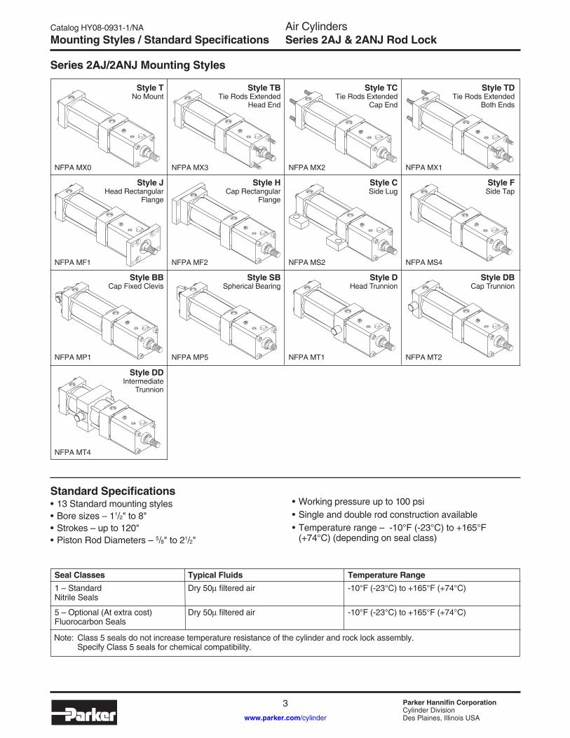
Series 2AJ/2ANJ Mounting Styles
Style T No Mount
NFPA MX0
Style TB Tie Rods Extended
Head End
NFPA MX3
Style TC Tie Rods Extended
Cap End
NFPA MX2
Style TD Tie Rods Extended
Both Ends
NFPA MX1
Style J Head Rectangular
Flange
NFPA MF1
Style H Cap Rectangular
Flange
NFPA MF2
Style C Side Lug
NFPA MS2
Style F Side Tap
NFPA MS4
Style BB Cap Fixed Clevis
NFPA MP1
Style SB Spherical Bearing
NFPA MP5
Style D Head Trunnion
NFPA MT1
Style DB Cap Trunnion
NFPA MT2
Style DD Intermediate
Trunnion
NFPA MT4
Standard Specifications• 13 Standard mounting styles• Bore sizes – 11/2" to 8"• Strokes – up to 120"• Piston Rod Diameters – 5/8" to 21/2"
• Working pressure up to 100 psi• Single and double rod construction available• Temperature range – -10°F (-23°C) to +165°F (+74°C) (depending on seal class)
Seal Classes1 – Standard Nitrile Seals
5 – Optional (At extra cost) Fluorocarbon Seals
Typical FluidsDry 50 filtered air
Dry 50 filtered air
Temperature Range-10°F (-23°C) to +165°F (+74°C)
-10°F (-23°C) to +165°F (+74°C)
Note: Class 5 seals do not increase temperature resistance of the cylinder and rock lock assembly. Specify Class 5 seals for chemical compatibility.

Air CylindersSeries 2AJ & 2ANJ Rod Lock
Catalog HY08-0931-1/NA
4 Parker Hannifin CorporationCylinder DivisionDes Plaines, Illinois USAwww.parker.com/cylinder
Model Code
Double Rod CylindersFor double rod cylinders, specify rod number and rod end symbols for both piston rods. A typical double rod model number would be:2" KJ2AJLU14A/14AX12"
2AJ / 2ANJ Model Code
2" C J 2AJ L U 1 4 A 12"
BoreSize
CushionHead
Double Rod
CylinderMounting
Style
Series
Piston
Ports1
Common Modifications
Piston Rod Number
Piston Rod Thread Style
Piston Rod Thread Type
Stroke
Specify bore size in inches
11/22
21/231/44568
Use “K” only if double rod cylinder is required.
Specify: T = No tie rods extendedTB = Tie rods ext. headTC = Tie rods ext. capTD = Tie rods ext. both ends J = Head rectangular flange H = Cap rectangular flange C = Side lugs F = Side tapBB = Cap fixed clevisSB = Spherical bearing D = Head trunnionDB = Cap trunnionDD = Intermediate trunnion
2AJ = Series 2A Cylinder with Piston Rod Lock2ANJ = Series 2AN Cylinder with Piston Rod Lock
L = Lipseal Piston
Specify:U = NPTF PortsR = BSPP Ports
V = Fluorocarbon2
For Single Rod Cylinders, select one only. Refer to rod number listing on pages 10 thru 20. See Cylinder Stroke Chart on page 7 for minimum piston rod diameter.
Specify: 4 = Small Male 8 = Intermediate Male 9 = Female55 = Flange Coupler 3 = Special(see note below)
Specify:A = UNFM = Metric
Specify Stroke Length Required in inches.
Special Modifications
Use “S” for Special Modifica-tion other than rod end, and specify modification.
C
Cushion Cap
To order thread style 3, specify “3” and give the desired dimensions for KK, A, and W or WF or furnish a dimensioned sketch.
Use “C” only if head end cushion is required.
Use “C” only if cap end cushion is required.
1 Port thread styles for base cylinder only. Standard rod lock port is NPTF and cannot be specified with this field entry. If a different rod lock port is required, place an 'S' for special in the Special Modification field and indicate the desired rod lock port thread style in the item notes.
2 Fluorocarbon seals for the 2AJ or 2ANJ are only for chemical compatibility and not for temperature resistance. The maximum rod lock operating temperature is +165°F.
Catalog HY08-0931-1/NA
5 Parker Hannifin CorporationCylinder DivisionDes Plaines, Illinois USAwww.parker.com/cylinder
Air CylindersSeries 2AJ & 2ANJ Rod LockRod Lock Connection / Specifications
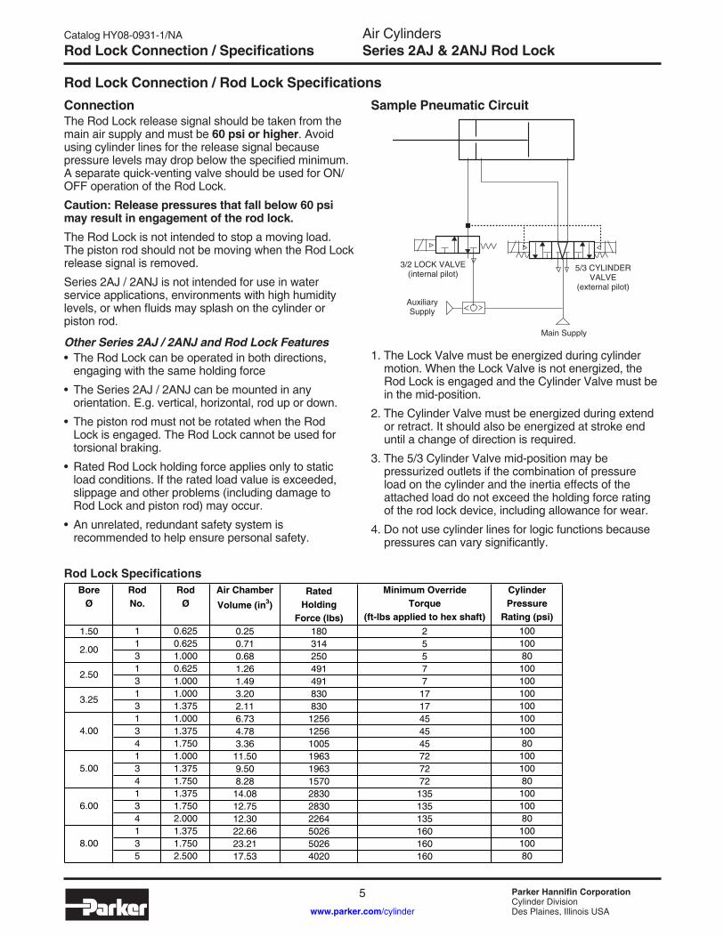
Rod Lock Connection / Rod Lock SpecificationsConnectionThe Rod Lock release signal should be taken from the main air supply and must be 60 psi or higher. Avoid using cylinder lines for the release signal because pressure levels may drop below the specified minimum. A separate quick-venting valve should be used for ON/OFF operation of the Rod Lock.
Caution: Release pressures that fall below 60 psi may result in engagement of the rod lock.The Rod Lock is not intended to stop a moving load. The piston rod should not be moving when the Rod Lock release signal is removed.
Series 2AJ / 2ANJ is not intended for use in water service applications, environments with high humidity levels, or when fluids may splash on the cylinder or piston rod.
Other Series 2AJ / 2ANJ and Rod Lock Features• The Rod Lock can be operated in both directions,
engaging with the same holding force
• The Series 2AJ / 2ANJ can be mounted in any orientation. E.g. vertical, horizontal, rod up or down.
• The piston rod must not be rotated when the Rod Lock is engaged. The Rod Lock cannot be used for torsional braking.
• Rated Rod Lock holding force applies only to static load conditions. If the rated load value is exceeded, slippage and other problems (including damage to Rod Lock and piston rod) may occur.
• An unrelated, redundant safety system is recommended to help ensure personal safety.
Sample Pneumatic Circuit
1. The Lock Valve must be energized during cylinder motion. When the Lock Valve is not energized, the Rod Lock is engaged and the Cylinder Valve must be in the mid-position.
2. The Cylinder Valve must be energized during extend or retract. It should also be energized at stroke end until a change of direction is required.
3. The 5/3 Cylinder Valve mid-position may be pressurized outlets if the combination of pressure load on the cylinder and the inertia effects of the attached load do not exceed the holding force rating of the rod lock device, including allowance for wear.
4. Do not use cylinder lines for logic functions because pressures can vary significantly.
3/2 LOCK VALVE(internal pilot)
Auxiliary Supply
Main Supply
5/3 CYLINDER VALVE
(external pilot)
1.50 1 0.625 0.25 180 2 1001 0.625 0.71 314 5 1003 1.000 0.68 250 5 801 0.625 1.26 491 7 1003 1.000 1.49 491 7 1001 1.000 3.20 830 17 1003 1.375 2.11 830 17 1001 1.000 6.73 1256 45 1003 1.375 4.78 1256 45 1004 1.750 3.36 1005 45 801 1.000 11.50 1963 72 1003 1.375 9.50 1963 72 1004 1.750 8.28 1570 72 801 1.375 14.08 2830 135 1003 1.750 12.75 2830 135 1004 2.000 12.30 2264 135 801 1.375 22.66 5026 160 1003 1.750 23.21 5026 160 1005 2.500 17.53 4020 160 80
CylinderPressure
Rating (psi)
RodØ
RatedHolding
Force (lbs)
Minimum OverrideTorque
(ft-lbs applied to hex shaft)
2.00
6.00
8.00
Air ChamberVolume (in3)
2.50
3.25
4.00
5.00
BoreØ
RodNo.
Rod Lock Specifications

Air CylindersSeries 2AJ & 2ANJ Rod Lock
Catalog HY08-0931-1/NA
6 Parker Hannifin CorporationCylinder DivisionDes Plaines, Illinois USAwww.parker.com/cylinder
Weight of Cylinder with Rod Lock
Cylinder WeightsTo determine the weight of a Series 2AJ or 2ANJ cylinder, first select the basic zero stroke weight for the mounting required, and then calculate the weight of the cylinder stroke and add the results to the basic weight. For extra rod extension, use piston rod weights per inch in Table B.
1 1/2 5/8 6.0 6.6 0.30 6.5 7.1 0.605/8 10.0 10.4 0.50 11.7 12.1 1.001 10.5 11.0 0.65 12.5 13.0 1.30
5/8 13.6 14.3 0.60 16.0 16.7 1.201 14.1 14.6 0.75 16.6 17.1 1.501 24.6 25.6 0.80 30.1 31.1 1.60
1 3/8 25.1 26.1 1.00 30.6 31.6 2.001 3/4 25.9 26.9 1.25 32.2 33.2 2.50
1 38.7 43.7 1.00 45.7 50.7 2.001 3/8 39.2 44.2 1.20 46.2 51.2 2.501 3/4 40.0 45.0 1.50 47.8 52.8 3.00
1 56.3 63.3 1.10 65.3 72.3 2.201 3/8 56.8 63.8 1.30 65.8 72.8 2.601 3/4 57.6 64.6 1.55 67.4 74.4 3.101 3/8 104.8 113.8 1.50 116.8 125.8 3.001 3/4 105.6 114.6 1.75 118.5 127.5 3.50
2 106.3 115.3 2.00 120.0 129.0 4.001 3/8 158.4 163.4 2.00 172.4 177.4 4.001 3/4 159.2 164.2 2.25 174.1 179.1 4.502 1/2 161.7 166.7 3.00 179.1 184.1 6.00
BoreØ
RodØ
3 1/4
2
Add Per Inch of StrokeKT, KTB, KTD
KF, KJKC, KD, KDD
2 1/2
4
Add Per Inch of Stroke
Double Rod CylindersBasic Weight - Zero Stroke
5
6
8
Single Rod CylindersBasic Weight - Zero Stroke
T, TB, TC, TDF, H, J
C, BB, SBD, DB, DD
Table A – Series 2AJ & 2ANJ Cylinder Weights in Pounds
Table B – Piston Rod Weights in PoundsRod
Ø5/8"1"
1 3/8"1 3/4"
2"2 1/2"
0.420.680.891.40
0.090.22
Piston RodWeight Per Inch

Catalog HY08-0931-1/NA
7 Parker Hannifin CorporationCylinder DivisionDes Plaines, Illinois USAwww.parker.com/cylinder
Air CylindersSeries 2AJ & 2ANJ Rod LockCylinder Stroke Chart
100 2 3 4 5 6 7 8 9 1000 2 3 4 5 6 7 8 9 10,000 2 3 4 5 6 7 8 9 100,000 2 310
20
30
40
50
60
300
200
100908070
THRUST–POUNDS
ROD DIAMETER
BA
SIC
LE
NG
TH–I
NC
HE
S
INC
HE
S O
F
STO
P T
UB
E
1
2
34567
CO
NS
ULT
FA
CTO
RY
58
1
134 2 21
2381
How to Use the ChartThe selection of a piston rod for thrust (push) conditions requires the following steps:1. Determine the type of cylinder mounting style and rod end
connection to be used. Then consult the chart below and find the “stroke factor” that corresponds to the conditions used.
2. Using this stroke factor, determine the “basic length” from the equation:
The graph is prepared for standard rod extensions beyond the face of the head. For rod extensions greater than standard, add the increase to the stroke in arriving at the “basic length.”
3. Find the load imposed for the thrust application by multiplying the full bore area of the cylinder by the system pressure.
4. Enter the graph along the values of “basic length” and “thrust” as found above and note the point of intersection:
A) The correct piston rod size is read from the diagonally curved line labeled “Rod Diameter” next above the point of intersection.
B) The required length of stop tube is read from the right of the graph by following the shaded band in which the point of intersection lies.
C) If required length of stop tube is in the region labeled “consult factory,” submit the following information for an individual analysis:
1) Cylinder mounting style.2) Rod end connection and method of guiding load.3) Bore, required stroke, length of rod extension (Dim. “A” and “W”) if
greater than standard, and series of cylinder used.4) Mounting position of cylinder. (Note: If at an angle or vertical,
specify direction of piston rod.)5) Operating pressure of cylinder if limited to less than standard
pressure for cylinder selected.
WarningPiston rods are not normally designed to absorb bending moments or loads which are perpendicular to the axis of piston rod motion. These additional loads can cause the piston rod end to fail. If these types of additional loads are expected to be imposed on the piston rods, their magnitude should be made known to our Engineering Department so they may be properly addressed. Additionally, cylinder users should always make sure that the piston rod is securely attached to the machine member.
Basic = Actual x Stroke Length Stroke Factor
Piston Rod — Stroke Selection Chart
Recommended Mounting Styles for Rod End StrokeMaximum Stroke and Thrust Loads Connection Case Factor
Groups 1 or 3Long stroke cylinders for thrust loads should be mounted using a heavy-duty mounting style at one end, firmly fixed and aligned to take the principal force. Additional mounting should be specified at the opposite end, which should be used for alignment and support. An intermediate support may also be desirable for long stroke cylinders mounted horizontally. Machine mounting pads can be adjustable for support mountings to achieve proper alignment.
Group 2Style D — Trunnion on Head
Style DD — Intermediate Trunnion
Style DB — Trunnion on Cap orStyle BB — Clevis on Cap
Fixed and Rigidly Guided
Pivoted and Rigidly Guided
Supported but not Rigidly Guided
Pivoted and Rigidly Guided
Pivoted and Rigidly Guided
Pivoted and Rigidly Guided
.50
.70
2.00
1.00
1.50
2.00
I
II
III
IV
V
VI

Air CylindersSeries 2AJ & 2ANJ Rod Lock
Catalog HY08-0931-1/NA
8 Parker Hannifin CorporationCylinder DivisionDes Plaines, Illinois USAwww.parker.com/cylinder
Stop Tubing / Mounting Classes
CUSHIONSLEEVE
UNTHREADEDPISTON
SPACERPISTON
(CAP END)(HEAD END)
LB + GROSS STROKEGROSS STROKE
NETSTROKE
TOTAL STOPTUBE LENGTH
Heavy-Duty ServiceFor Thrust Loads Mtg. Style CFor Tension Loads Mtg. Style C
Medium-Duty ServiceFor Thrust Loads Mtg. Style FFor Tension Loads Mts. Style F
Heavy-Duty ServiceFor Thrust Loads Mtg. Styles DD, DFor Tension Loads Mtg. Styles BB, DD, D, DB
Medium-Duty ServiceFor Thrust Loads Mtg. Style BBFor Tension Loads Mtg. Style BB
Group 3 FIXED MOUNTS which do not absorb force on the centerline.
Stop TubingStop tube is recommended to lengthen the distance between the gland and piston to reduce bearing loads when the cylinder is fully extended. This is especially true of horizontally mounted and long stroke cylinders. Long stroke cylinders achieve additional stability through the use of a stop tube.
When specifying cylinders with long stroke and stop tube, be sure to call out the net stroke and the length of the stop tube. Machine design can be continued without delay by laying in a cylinder equivalent in length to the NET STROKE PLUS STOP TUBE LENGTH, which is referred to as GROSS STROKE.
Refer to piston rod/stroke selection chart to determine stop tube length.
Double piston design is supplied on air cylinders with cushion head end or both ends.
This design is supplied on cushion cap end non cushion cylinders.
Mounting ClassesStandard mountings for fluid power cylinders fall into three basic groups. The groups can be summarized as follows:Group 1 – Straight Line Force Transfer with fixed mounts
which absorb force on cylinder centerline.Group 2 – Pivot Force Transfer. Pivot mountings permit a
cylinder to change its alignment in one plane.Group 3 – Straight Line Force Transfer with fixed
mounts which do not absorb force on cylinder centerline.
Because a cylinder’s mounting directly affects the maxi-mum pressure at which the cylinder can be used, the chart below should be helpful in selection of the proper mounting combination for your application. Stroke length, piston rod connection to load, extra piston rod length over standard, etc., should be considered for thrust loads. Alloy steel mounting bolts are recommended for all mounting styles, and thrust keys are recommended for Group 3.
Group 1 FIXED MOUNTS which absorb force on cylinder centerline.
Heavy-Duty ServiceFor Thrust Loads Mtg. Style TCFor Tension Loads Mtg. Style TB
Medium -Duty ServiceFor Thrust Loads Mtg. Style HFor Tension Loads Mtg. Style J
Group 2 PIVOT MOUNTS which absorb force on cylinder centerline.(PISTON ROD) (CAP END)(HEAD END) STOP
TUBE PISTON
LB + GROSS STROKEGROSS STROKE
STOPTUBELENGTH
NET STROKE

Catalog HY08-0931-1/NA
9 Parker Hannifin CorporationCylinder DivisionDes Plaines, Illinois USAwww.parker.com/cylinder
Air CylindersSeries 2AJ & 2ANJ Rod LockNotes
NOTES

Air CylindersSeries 2AJ & 2ANJ Rod Lock
Catalog HY08-0931-1/NA
10 Parker Hannifin CorporationCylinder DivisionDes Plaines, Illinois USAwww.parker.com/cylinder
T Mount – Single Rod End
T Mount Single Rod End – Envelope and Mounting Dimensions
Rod End DimensionsThread Style 8 Thread Style 9Thread Style 4
“Special” Thread Style 3Special thread, extension, rod eye, blank, etc. are also available. To order, specify “Style 3” and give desired dimensions for KK, A, & WF. If otherwise special furnish dimensional sketch.
T Mount Single Rod End – Rod Dimensions
T Mount – Single Rod End 11/2" to 8" Bore Size
ROD LOCKUNLOCK
1
2
3
4
RSQ.
ESQ.
Y P + STROKEH
LG + STROKEKGNR
.23
J
EEWF
ØMMN1
N2
N3F1
Q EF
BoreØ
E EENPTF
EFNPTF
F1 G J K N3Hex
NR(Max.)
R P Add
Stroke1.50 2.00 3/8 1/8 0.25 1.50 1.00 0.25 5/16 0.24 1.43 2.252.00 2.50 3/8 1/8 0.31 1.50 1.00 0.32 1/2 0.32 1.84 2.252.50 3.00 3/8 1/8 0.31 1.50 1.00 0.32 1/2 0.32 2.19 2.383.25 3.75 1/2 1/4 0.38 1.75 1.25 0.38 5/8 0.41 2.76 2.634.00 4.50 1/2 1/4 0.38 1.75 1.25 0.38 7/8 0.55 3.32 2.635.00 5.50 1/2 1/4 0.50 1.75 1.25 0.44 7/8 0.55 4.10 2.886.00 6.50 3/4 1/4 0.50 2.00 1.50 0.44 1 5/16 0.81 4.88 3.138.00 8.50 3/4 1/4 0.63 2.00 1.50 0.56 1 5/16 0.81 6.44 3.25
CCStyle 8
KKStyle4 & 9
A B +.000-.002
C D H N1 N2 NA Q VD WF Y
1.50 1 0.625 1/2-20 7/16-20 0.75 1.124 0.38 0.50 2.63 0.22 0.14 0.56 0.72 0.38 1.00 4.81 6.501 0.625 1/2-20 7/16-20 0.75 1.124 0.38 0.50 2.88 0.34 0.13 0.56 0.90 0.38 1.00 5.13 6.813 1.000 7/8-14 3/4-16 1.13 1.499 0.50 0.88 3.88 0.34 0.15 0.94 1.07 0.50 1.38 6.50 7.811 0.625 1/2-20 7/16-20 0.75 1.124 0.38 0.50 2.88 0.35 0.15 0.56 0.76 0.50 1.00 5.13 6.943 1.000 7/8-14 3/4-16 1.13 1.499 0.50 0.88 4.00 0.35 0.15 0.94 1.12 0.50 1.38 6.63 8.061 1.000 7/8-14 3/4-16 1.13 1.499 0.50 0.88 4.50 0.63 0.18 0.94 1.51 0.50 1.38 7.31 9.133 1.375 1 1/4-12 1-14 1.63 1.999 0.63 1.13 4.88 0.81 0.25 1.31 1.65 0.63 1.63 7.94 9.501 1.000 7/8-14 3/4-16 1.13 1.499 0.50 0.88 4.88 0.63 0.24 0.94 1.73 0.50 1.38 7.69 9.503 1.375 1 1/4-12 1-14 1.63 1.999 0.63 1.13 5.13 0.77 0.28 1.31 1.68 0.75 1.63 8.19 9.754 1.750 1 1/2-12 1 1/4-12 2.00 2.374 0.75 1.50 5.50 1.03 0.26 1.69 2.09 0.88 1.88 8.81 10.131 1.000 7/8-14 3/4-16 1.13 1.499 0.50 0.88 5.38 0.72 0.22 0.94 2.00 0.50 1.38 8.31 10.383 1.375 1 1/4-12 1-14 1.63 1.999 0.63 1.13 5.75 0.72 0.22 1.31 2.33 0.75 1.63 8.94 10.754 1.750 1 1/2-12 1 1/4-12 2.00 2.374 0.75 1.50 6.38 1.10 0.22 1.69 2.30 0.88 1.88 9.81 11.381 1.375 1 1/4-12 1-14 1.63 1.999 0.63 1.13 6.38 1.17 0.18 1.31 2.71 0.76 1.63 9.69 11.883 1.750 1 1/2-12 1 1/4-12 2.00 2.374 0.75 1.50 6.88 1.50 0.18 1.69 3.07 0.88 1.88 10.44 12.384 2.000 1 3/4-12 1 1/2-12 2.25 2.624 0.88 1.69 7.00 1.49 0.18 1.94 3.18 1.25 2.00 10.69 12.501 1.375 1 1/4-12 1-14 1.63 1.999 0.63 1.13 6.63 1.31 0.18 1.31 2.89 0.76 1.63 10.06 12.383 1.750 1 1/2-12 1 1/4-12 2.00 2.374 0.75 1.50 7.13 1.57 0.18 1.69 3.15 0.88 1.88 10.81 12.885 2.500 2 1/4-12 1 7/8-12 3.00 3.124 1.00 2.06 7.50 1.22 0.30 2.38 3.15 1.38 2.25 11.56 13.25
RodNo.
MMRod
Ø
ThreadLGAdd
Stroke
Rod Extensions and Pilot Dimensions
5.00
6.00
8.00
BoreØ
2.00
2.50
3.25
4.00
ØB
ØNA
ØMM
ROD LOCKUNLOCKD WRENCH
FLATS
WF
VD
A
CKK
ROD LOCKUNLOCKD WRENCH
FLATSØMM
ØB
ØNA
WFAVDCC
C
ROD LOCKUNLOCKD WRENCH
FLATS
WF
VD
ØB
ØNA
A
ØMM
C
KK

Catalog HY08-0931-1/NA
11 Parker Hannifin CorporationCylinder DivisionDes Plaines, Illinois USAwww.parker.com/cylinder
Air CylindersSeries 2AJ & 2ANJ Rod LockTB, TC, TD Mount – Single Rod End
TB, TC, TD Mount Single Rod End – Envelope and Mounting Dimensions
Rod End DimensionsThread Style 8 Thread Style 9Thread Style 4
“Special” Thread Style 3Special thread, extension, rod eye, blank, etc. are also available. To order, specify “Style 3” and give desired dimensions for KK, A, & WF. If otherwise special furnish dimensional sketch.
TB, TC, TD Mount Single Rod End – Rod Dimensions
TD Mount – Single Rod End* 11/2" to 8" Bore Size
ØB
ØNA
ØMM
ROD LOCKUNLOCKD WRENCH
FLATS
WF
VD
A
CKK
ROD LOCKUNLOCKD WRENCH
FLATSØMM
ØB
ØNA
WFAVDCC
C
ROD LOCKUNLOCKD WRENCH
FLATS
WF
VD
ØB
ØNA
A
ØMM
C
KK
ESQ.
RSQ.
LG + STROKEWFDD
1
2
3
4
KBB
AAK
BB
BoreØ
AA BB DD E K R
1.50 2.02 1.00 1/4-28 2.00 0.25 1.432.00 2.60 1.13 5/16-24 2.50 0.31 1.842.50 3.10 1.13 5/16-24 3.00 0.31 2.193.25 3.90 1.38 3/8-24 3.75 0.38 2.764.00 4.70 1.38 3/8-24 4.50 0.38 3.325.00 5.80 1.81 1/2-20 5.50 0.44 4.106.00 6.90 1.81 1/2-20 6.50 0.44 4.888.00 9.10 2.31 5/8-18 8.50 0.31 6.44
1.50 1 0.625 1/2-20 7/16-20 0.75 1.124 0.38 0.50 0.56 0.38 1.00 6.501 0.625 1/2-20 7/16-20 0.75 1.124 0.38 0.50 0.56 0.38 1.00 6.813 1.000 7/8-14 3/4-16 1.13 1.499 0.50 0.88 0.94 0.50 1.38 7.811 0.625 1/2-20 7/16-20 0.75 1.124 0.38 0.50 0.56 0.50 1.00 6.943 1.000 7/8-14 3/4-16 1.13 1.499 0.50 0.88 0.94 0.50 1.38 8.061 1.000 7/8-14 3/4-16 1.13 1.499 0.50 0.88 0.94 0.50 1.38 9.133 1.375 1 1/4-12 1-14 1.63 1.999 0.63 1.13 1.31 0.63 1.63 9.501 1.000 7/8-14 3/4-16 1.13 1.499 0.50 0.88 0.94 0.50 1.38 9.503 1.375 1 1/4-12 1-14 1.63 1.999 0.63 1.13 1.31 0.75 1.63 9.754 1.750 1 1/2-12 1 1/4-12 2.00 2.374 0.75 1.50 1.69 0.88 1.88 10.131 1.000 7/8-14 3/4-16 1.13 1.499 0.50 0.88 0.94 0.50 1.38 10.383 1.375 1 1/4-12 1-14 1.63 1.999 0.63 1.13 1.31 0.75 1.63 10.754 1.750 1 1/2-12 1 1/4-12 2.00 2.374 0.75 1.50 1.69 0.88 1.88 11.381 1.375 1 1/4-12 1-14 1.63 1.999 0.63 1.13 1.31 0.75 1.63 11.883 1.750 1 1/2-12 1 1/4-12 2.00 2.374 0.75 1.50 1.69 0.88 1.88 12.384 2.000 1 3/4-12 1 1/2-12 2.25 2.624 0.88 1.69 1.94 1.25 2.00 12.501 1.375 1 1/4-12 1-14 1.63 1.999 0.63 1.13 1.31 0.75 1.63 12.383 1.750 1 1/2-12 1 1/4-12 2.00 2.374 0.75 1.50 1.69 0.88 1.88 12.885 2.500 2 1/4-12 1 7/8-12 3.00 3.124 1.00 2.06 2.38 1.38 2.25 13.25
MMRod
Ø
2.00
6.00
8.00
4.00
5.00
2.50
3.25
BoreØ
RodNo.
ThreadCC
Style 8KK
Style4 & 9
NARod Extensions and Pilot Dimensions
VD WF LGAdd
Stroke
A B +.000-.002
C D
* Style TB – Tie Rods Extended Head End, and Style TC – Tie Rods Extended Cap End can be dimensioned from Style TD shown.
Air CylindersSeries 2AJ & 2ANJ Rod Lock
Catalog HY08-0931-1/NA
12 Parker Hannifin CorporationCylinder DivisionDes Plaines, Illinois USAwww.parker.com/cylinder
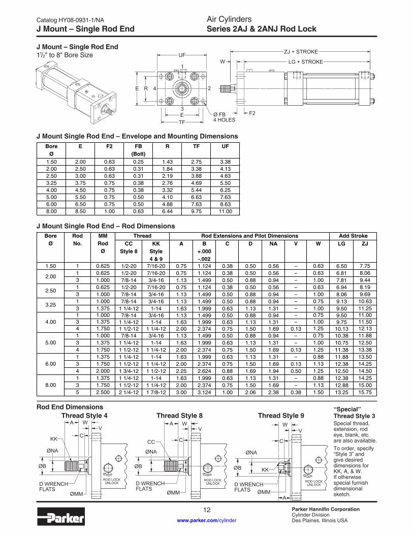
J Mount – Single Rod End
J Mount Single Rod End – Envelope and Mounting Dimensions
Rod End DimensionsThread Style 8 Thread Style 9Thread Style 4
“Special” Thread Style 3Special thread, extension, rod eye, blank, etc. are also available. To order, specify “Style 3” and give desired dimensions for KK, A, & W. If otherwise special furnish dimensional sketch.
J Mount Single Rod End – Rod Dimensions
J Mount – Single Rod End 11/2" to 8" Bore Size
LG + STROKE1
2
3
4
UF
E
E F2
W
ZJ + STROKE
R
TFØ FB4 HOLES
BoreØ
E F2 FB (Bolt)
R TF UF
1.50 2.00 0.63 0.25 1.43 2.75 3.382.00 2.50 0.63 0.31 1.84 3.38 4.132.50 3.00 0.63 0.31 2.19 3.88 4.633.25 3.75 0.75 0.38 2.76 4.69 5.504.00 4.50 0.75 0.38 3.32 5.44 6.255.00 5.50 0.75 0.50 4.10 6.63 7.636.00 6.50 0.75 0.50 4.88 7.63 8.638.00 8.50 1.00 0.63 6.44 9.75 11.00
1.50 1 0.625 1/2-20 7/16-20 0.75 1.124 0.38 0.50 0.56 – 0.63 6.50 7.751 0.625 1/2-20 7/16-20 0.75 1.124 0.38 0.50 0.56 – 0.63 6.81 8.063 1.000 7/8-14 3/4-16 1.13 1.499 0.50 0.88 0.94 – 1.00 7.81 9.441 0.625 1/2-20 7/16-20 0.75 1.124 0.38 0.50 0.56 – 0.63 6.94 8.193 1.000 7/8-14 3/4-16 1.13 1.499 0.50 0.88 0.94 – 1.00 8.06 9.691 1.000 7/8-14 3/4-16 1.13 1.499 0.50 0.88 0.94 – 0.75 9.13 10.633 1.375 1 1/4-12 1-14 1.63 1.999 0.63 1.13 1.31 – 1.00 9.50 11.251 1.000 7/8-14 3/4-16 1.13 1.499 0.50 0.88 0.94 – 0.75 9.50 11.003 1.375 1 1/4-12 1-14 1.63 1.999 0.63 1.13 1.31 – 1.00 9.75 11.504 1.750 1 1/2-12 1 1/4-12 2.00 2.374 0.75 1.50 1.69 0.13 1.25 10.13 12.131 1.000 7/8-14 3/4-16 1.13 1.499 0.50 0.88 0.94 – 0.75 10.38 11.883 1.375 1 1/4-12 1-14 1.63 1.999 0.63 1.13 1.31 – 1.00 10.75 12.504 1.750 1 1/2-12 1 1/4-12 2.00 2.374 0.75 1.50 1.69 0.13 1.25 11.38 13.381 1.375 1 1/4-12 1-14 1.63 1.999 0.63 1.13 1.31 – 0.88 11.88 13.503 1.750 1 1/2-12 1 1/4-12 2.00 2.374 0.75 1.50 1.69 0.13 1.13 12.38 14.254 2.000 1 3/4-12 1 1/2-12 2.25 2.624 0.88 1.69 1.94 0.50 1.25 12.50 14.501 1.375 1 1/4-12 1-14 1.63 1.999 0.63 1.13 1.31 – 0.88 12.38 14.253 1.750 1 1/2-12 1 1/4-12 2.00 2.374 0.75 1.50 1.69 – 1.13 12.88 15.005 2.500 2 1/4-12 1 7/8-12 3.00 3.124 1.00 2.06 2.38 0.38 1.50 13.25 15.75
A B +.000-.002
C DThread
CCStyle 8
KKStyle4 & 9
Add StrokeLG ZJNA
Rod Extensions and Pilot DimensionsV W
MMRod
Ø
2.00
6.00
8.00
4.00
5.00
2.50
3.25
BoreØ
RodNo.
ØB
ØNA
ØMM
ROD LOCKUNLOCKD WRENCH
FLATS
WAV
CKK
ROD LOCKUNLOCKD WRENCH
FLATS
A WV
CCC
ØB
ØNA
ØMM
ROD LOCKUNLOCKD WRENCH
FLATS
VW
ØNA
ØMM
ØB
C
A
KK

Catalog HY08-0931-1/NA
13 Parker Hannifin CorporationCylinder DivisionDes Plaines, Illinois USAwww.parker.com/cylinder
Air CylindersSeries 2AJ & 2ANJ Rod LockH Mount – Single Rod End
H Mount Single Rod End – Envelope and Mounting Dimensions
Rod End DimensionsThread Style 8 Thread Style 9Thread Style 4
“Special” Thread Style 3Special thread, extension, rod eye, blank, etc. are also available. To order, specify “Style 3” and give desired dimensions for KK, A, & WF. If otherwise special furnish dimensional sketch.
H Mount Single Rod End – Rod Dimensions
H Mount – Single Rod End 11/2" to 8" Bore Size
ØB
ØNA
ØMM
ROD LOCKUNLOCKD WRENCH
FLATS
WF
VD
A
CKK
ROD LOCKUNLOCKD WRENCH
FLATSØMM
ØB
ØNA
WFAVDCC
C
ROD LOCKUNLOCKD WRENCH
FLATS
WF
VD
ØB
ØNA
A
ØMM
C
KK
1
2
3
4
WF
ZF + STROKE
LB + STROKE
F
UF
E
E Ø FB4 HOLES
R
TF
BoreØ
E F FB (Bolt)
R TF UF
1.50 2.00 0.38 0.25 1.43 2.75 3.382.00 2.50 0.38 0.31 1.84 3.38 4.132.50 3.00 0.38 0.31 2.19 3.88 4.633.25 3.75 0.63 0.38 2.76 4.69 5.504.00 4.50 0.63 0.38 3.32 5.44 6.255.00 5.50 0.63 0.50 4.10 6.63 7.636.00 6.50 0.75 0.50 4.88 7.63 8.638.00 8.50 – 0.69* 7.57* 7.57* 8.50* * Style HB Square Cap mount supplied in 8" bore.
1.50 1 0.625 1/2-20 7/16-20 0.75 1.124 0.38 0.50 0.56 0.38 1.00 6.88 7.881 0.625 1/2-20 7/16-20 0.75 1.124 0.38 0.50 0.56 0.38 1.00 7.19 8.193 1.000 7/8-14 3/4-16 1.13 1.499 0.50 0.88 0.94 0.50 1.38 8.19 9.561 0.625 1/2-20 7/16-20 0.75 1.124 0.38 0.50 0.56 0.50 1.00 7.31 8.313 1.000 7/8-14 3/4-16 1.13 1.499 0.50 0.88 0.94 0.50 1.38 8.44 9.811 1.000 7/8-14 3/4-16 1.13 1.499 0.50 0.88 0.94 0.50 1.38 9.75 11.133 1.375 1 1/4-12 1-14 1.63 1.999 0.63 1.13 1.31 0.63 1.63 10.13 11.751 1.000 7/8-14 3/4-16 1.13 1.499 0.50 0.88 0.94 0.50 1.38 10.13 11.503 1.375 1 1/4-12 1-14 1.63 1.999 0.63 1.13 1.31 0.75 1.63 10.38 12.004 1.750 1 1/2-12 1 1/4-12 2.00 2.374 0.75 1.50 1.69 0.88 1.88 10.75 12.631 1.000 7/8-14 3/4-16 1.13 1.499 0.50 0.88 0.94 0.50 1.38 11.00 12.383 1.375 1 1/4-12 1-14 1.63 1.999 0.63 1.13 1.31 0.75 1.63 11.38 13.004 1.750 1 1/2-12 1 1/4-12 2.00 2.374 0.75 1.50 1.69 0.88 1.88 12.00 13.881 1.375 1 1/4-12 1-14 1.63 1.999 0.63 1.13 1.31 0.75 1.63 12.63 14.253 1.750 1 1/2-12 1 1/4-12 2.00 2.374 0.75 1.50 1.69 0.88 1.88 13.13 15.004 2.000 1 3/4-12 1 1/2-12 2.25 2.624 0.88 1.69 1.94 1.25 2.00 13.25 15.251 1.375 1 1/4-12 1-14 1.63 1.999 0.63 1.13 1.31 0.75 1.63 12.38* 14.00*3 1.750 1 1/2-12 1 1/4-12 2.00 2.374 0.75 1.50 1.69 0.88 1.88 12.88* 14.25*5 2.500 2 1/4-12 1 7/8-12 3.00 3.124 1.00 2.06 2.38 1.38 2.25 13.25* 15.50*
3.25
BoreØ
RodNo.
Add StrokeLB ZFNA
Rod Extensions and Pilot DimensionsVD WFD
ThreadCC
Style 8KK
Style4 & 9
8.00
A B +.000-.002
CMMRod
Ø
2.00
6.00
4.00
5.00
2.50

Air CylindersSeries 2AJ & 2ANJ Rod Lock
Catalog HY08-0931-1/NA
14 Parker Hannifin CorporationCylinder DivisionDes Plaines, Illinois USAwww.parker.com/cylinder
C Mount – Single Rod End
C Mount Single Rod End – Envelope and Mounting Dimensions
Rod End DimensionsThread Style 8 Thread Style 9Thread Style 4
“Special” Thread Style 3Special thread, extension, rod eye, blank, etc. are also available. To order, specify “Style 3” and give desired dimensions for KK, A, & WF. If otherwise special furnish dimensional sketch.
C Mount Single Rod End – Rod Dimensions
C Mount – Single Rod End 11/2" to 8" Bore Size
ØB
ØNA
ØMM
ROD LOCKUNLOCKD WRENCH
FLATS
WF
VD
A
CKK
ROD LOCKUNLOCKD WRENCH
FLATSØMM
ØB
ØNA
WFAVDCC
C
ROD LOCKUNLOCKD WRENCH
FLATS
WF
VD
ØB
ØNA
A
ØMM
C
KK
1
2
3
4
WF
-.005-.010 ST
SW SWXS SS + STROKE
ESQ.
SW TS
E/2
SU
LG + STROKE
SW
US
Ø SB4 HOLES
SU
BoreØ
E SB (Bolt)
ST SU SW TS US SS Add Stroke
1.50 2.00 0.38 0.50 0.94 0.38 2.75 3.50 2.882.00 2.50 0.38 0.50 0.94 0.38 3.25 4.00 2.882.50 3.00 0.38 0.50 0.94 0.38 3.75 4.50 3.003.25 3.75 0.50 0.75 1.25 0.50 4.75 5.75 3.254.00 4.50 0.50 0.75 1.25 0.50 5.50 6.50 3.255.00 5.50 0.75 1.00 1.56 0.69 6.88 8.25 3.136.00 6.50 0.75 1.00 1.56 0.69 7.88 9.25 3.638.00 8.50 0.75 1.00 1.56 0.69 9.88 11.25 3.75
1.50 1 0.625 1/2-20 7/16-20 0.75 1.124 0.38 0.50 0.56 0.38 1.00 4.25 6.501 0.625 1/2-20 7/16-20 0.75 1.124 0.38 0.50 0.56 0.38 1.00 4.56 6.813 1.000 7/8-14 3/4-16 1.13 1.499 0.50 0.88 0.94 0.50 1.38 5.94 7.811 0.625 1/2-20 7/16-20 0.75 1.124 0.38 0.50 0.56 0.50 1.00 4.56 6.943 1.000 7/8-14 3/4-16 1.13 1.499 0.50 0.88 0.94 0.50 1.38 6.06 8.061 1.000 7/8-14 3/4-16 1.13 1.499 0.50 0.88 0.94 0.50 1.38 6.75 9.133 1.375 1 1/4-12 1-14 1.63 1.999 0.63 1.13 1.31 0.63 1.63 7.38 9.501 1.000 7/8-14 3/4-16 1.13 1.499 0.50 0.88 0.94 0.50 1.38 7.13 9.503 1.375 1 1/4-12 1-14 1.63 1.999 0.63 1.13 1.31 0.75 1.63 7.63 9.754 1.750 1 1/2-12 1 1/4-12 2.00 2.374 0.75 1.50 1.69 0.88 1.88 8.25 10.131 1.000 7/8-14 3/4-16 1.13 1.499 0.50 0.88 0.94 0.50 1.38 7.94 10.383 1.375 1 1/4-12 1-14 1.63 1.999 0.63 1.13 1.31 0.75 1.63 8.56 10.754 1.750 1 1/2-12 1 1/4-12 2.00 2.374 0.75 1.50 1.69 0.88 1.88 9.44 11.381 1.375 1 1/4-12 1-14 1.63 1.999 0.63 1.13 1.31 0.75 1.63 9.19 11.883 1.750 1 1/2-12 1 1/4-12 2.00 2.374 0.75 1.50 1.69 0.88 1.88 9.94 12.384 2.000 1 3/4-12 1 1/2-12 2.25 2.624 0.88 1.69 1.94 1.25 2.00 10.19 12.501 1.375 1 1/4-12 1-14 1.63 1.999 0.63 1.13 1.31 0.75 1.63 9.56 12.383 1.750 1 1/2-12 1 1/4-12 2.00 2.374 0.75 1.50 1.69 0.88 1.88 10.31 12.885 2.500 2 1/4-12 1 7/8-12 3.00 3.124 1.00 2.06 2.38 1.38 2.25 11.06 13.25
Rod Extensions and Pilot DimensionsLGAdd
Stroke
MMRod
Ø
2.00
ThreadCC
Style 8KK
Style4 & 9
NA VD WF
6.00
8.00
4.00
5.00
2.50
3.25
BoreØ
RodNo. XSA B
+.000-.002
C D

Catalog HY08-0931-1/NA
15 Parker Hannifin CorporationCylinder DivisionDes Plaines, Illinois USAwww.parker.com/cylinder
Air CylindersSeries 2AJ & 2ANJ Rod LockF Mount – Single Rod End
F Mount Single Rod End – Envelope and Mounting Dimensions
Rod End DimensionsThread Style 8 Thread Style 9Thread Style 4
“Special” Thread Style 3Special thread, extension, rod eye, blank, etc. are also available. To order, specify “Style 3” and give desired dimensions for KK, A, & WF. If otherwise special furnish dimensional sketch.
F Mount Single Rod End – Rod Dimensions
F Mount – Single Rod End 11/2" to 8" Bore Size
ØB
ØNA
ØMM
ROD LOCKUNLOCKD WRENCH
FLATS
WF
VD
A
CKK
ROD LOCKUNLOCKD WRENCH
FLATSØMM
ØB
ØNA
WFAVDCC
C
ROD LOCKUNLOCKD WRENCH
FLATS
WF
VD
ØB
ØNA
A
ØMM
C
KK
1
2
3
4
WF
ESQ.
TN NT THREAD, ND DEEP4 TAPPED MTG. HOLES
XT SN + STROKE
LG + STROKE
-.005-.010E/2
BoreØ
E ND NT TN SN Add Stroke
1.50 2.00 0.31 1/4-20 0.63 2.252.00 2.50 0.34 5/16-18 0.88 2.252.50 3.00 0.44 3/8-16 1.25 2.383.25 3.75 0.50 1/2-13 1.50 2.634.00 4.50 0.63 1/2-13 2.06 2.635.00 5.50 0.75 5/8-11 2.69 2.886.00 6.50 0.88 3/4-10 3.25 3.138.00 8.50 1.13 3/4-10 4.25 3.25
1.50 1 0.625 1/2-20 7/16-20 0.75 1.124 0.38 0.50 0.56 0.38 1.00 4.81 6.501 0.625 1/2-20 7/16-20 0.75 1.124 0.38 0.50 0.56 0.38 1.00 5.13 6.813 1.000 7/8-14 3/4-16 1.13 1.499 0.50 0.88 0.94 0.50 1.38 6.50 7.811 0.625 1/2-20 7/16-20 0.75 1.124 0.38 0.50 0.56 0.50 1.00 5.13 6.943 1.000 7/8-14 3/4-16 1.13 1.499 0.50 0.88 0.94 0.50 1.38 6.63 8.061 1.000 7/8-14 3/4-16 1.13 1.499 0.50 0.88 0.94 0.50 1.38 7.31 9.133 1.375 1 1/4-12 1-14 1.63 1.999 0.63 1.13 1.31 0.63 1.63 7.94 9.501 1.000 7/8-14 3/4-16 1.13 1.499 0.50 0.88 0.94 0.50 1.38 7.69 9.503 1.375 1 1/4-12 1-14 1.63 1.999 0.63 1.13 1.31 0.75 1.63 8.19 9.754 1.750 1 1/2-12 1 1/4-12 2.00 2.374 0.75 1.50 1.69 0.88 1.88 8.81 10.131 1.000 7/8-14 3/4-16 1.13 1.499 0.50 0.88 0.94 0.50 1.38 8.31 10.383 1.375 1 1/4-12 1-14 1.63 1.999 0.63 1.13 1.31 0.75 1.63 8.94 10.754 1.750 1 1/2-12 1 1/4-12 2.00 2.374 0.75 1.50 1.69 0.88 1.88 9.81 11.381 1.375 1 1/4-12 1-14 1.63 1.999 0.63 1.13 1.31 0.75 1.63 9.69 11.883 1.750 1 1/2-12 1 1/4-12 2.00 2.374 0.75 1.50 1.69 0.88 1.88 10.44 12.384 2.000 1 3/4-12 1 1/2-12 2.25 2.624 0.88 1.69 1.94 1.25 2.00 10.69 12.501 1.375 1 1/4-12 1-14 1.63 1.999 0.63 1.13 1.31 0.75 1.63 10.06 12.383 1.750 1 1/2-12 1 1/4-12 2.00 2.374 0.75 1.50 1.69 0.88 1.88 10.81 12.885 2.500 2 1/4-12 1 7/8-12 3.00 3.124 1.00 2.06 2.38 1.38 2.25 11.56 13.25
LGAdd
Stroke
C DBore
ØRodNo.
ThreadCC
Style 8KK
Style4 & 9
Rod Extensions and Pilot DimensionsXT
2.00
6.00
8.00
4.00
5.00
2.50
3.25
MMRod
ØNA VD WFA B
+.000-.002

Air CylindersSeries 2AJ & 2ANJ Rod Lock
Catalog HY08-0931-1/NA
16 Parker Hannifin CorporationCylinder DivisionDes Plaines, Illinois USAwww.parker.com/cylinder
BB Mount – Single Rod End
BB Mount Single Rod End – Envelope and Mounting Dimensions
Rod End DimensionsThread Style 8 Thread Style 9Thread Style 4
“Special” Thread Style 3Special thread, extension, rod eye, blank, etc. are also available. To order, specify “Style 3” and give desired dimensions for KK, A, & WF. If otherwise special furnish dimensional sketch.
BB Mount Single Rod End – Rod Dimensions
BB Mount – Single Rod End 11/2" to 8" Bore Size
ØB
ØNA
ØMM
ROD LOCKUNLOCKD WRENCH
FLATS
WF
VD
A
CKK
ROD LOCKUNLOCKD WRENCH
FLATSØMM
ØB
ØNA
WFAVDCC
C
ROD LOCKUNLOCKD WRENCH
FLATS
WF
VD
ØB
ØNA
A
ØMM
C
KK
1
2
3
4
CB
WF LG + STROKE
CW CW
CD
L M
MRLR
ZC + STROKE
XC + STROKE
ESQ.
BoreØ
CB CD * +.000–.002
CW E L LR M MR
1.50 0.75 0.501 0.50 2.00 0.75 0.75 0.50 0.632.00 0.75 0.501 0.50 2.50 0.75 0.75 0.50 0.632.50 0.75 0.501 0.50 3.00 0.75 0.75 0.50 0.633.25 1.25 0.751 0.63 3.75 1.25 1.00 0.75 0.944.00 1.25 0.751 0.63 4.50 1.25 1.00 0.75 0.945.00 1.25 0.751 0.63 5.50 1.25 1.00 0.75 0.946.00 1.50 1.001 0.75 6.50 1.50 1.25 1.00 1.198.00 1.50 1.001 0.75 8.50 1.50 1.25 1.00 1.19 * Dimension CD is pin diameter.
1.50 1 0.625 1/2-20 7/16-20 0.75 1.124 0.38 0.50 0.56 0.38 1.00 6.50 8.25 8.751 0.625 1/2-20 7/16-20 0.75 1.124 0.38 0.50 0.56 0.38 1.00 6.81 8.56 9.063 1.000 7/8-14 3/4-16 1.13 1.499 0.50 0.88 0.94 0.50 1.38 7.81 9.94 10.441 0.625 1/2-20 7/16-20 0.75 1.124 0.38 0.50 0.56 0.50 1.00 6.94 8.69 9.193 1.000 7/8-14 3/4-16 1.13 1.499 0.50 0.88 0.94 0.50 1.38 8.06 10.19 10.691 1.000 7/8-14 3/4-16 1.13 1.499 0.50 0.88 0.94 0.50 1.38 9.13 11.75 12.503 1.375 1 1/4-12 1-14 1.63 1.999 0.63 1.13 1.31 0.63 1.63 9.50 12.38 13.131 1.000 7/8-14 3/4-16 1.13 1.499 0.50 0.88 0.94 0.50 1.38 9.50 12.13 12.883 1.375 1 1/4-12 1-14 1.63 1.999 0.63 1.13 1.31 0.75 1.63 9.75 12.63 13.384 1.750 1 1/2-12 1 1/4-12 2.00 2.374 0.75 1.50 1.69 0.88 1.88 10.13 13.25 14.001 1.000 7/8-14 3/4-16 1.13 1.499 0.50 0.88 0.94 0.50 1.38 10.38 13.00 13.753 1.375 1 1/4-12 1-14 1.63 1.999 0.63 1.13 1.31 0.75 1.63 10.75 13.63 14.384 1.750 1 1/2-12 1 1/4-12 2.00 2.374 0.75 1.50 1.69 0.88 1.88 11.38 14.50 15.251 1.375 1 1/4-12 1-14 1.63 1.999 0.63 1.13 1.31 0.75 1.63 11.88 15.00 16.003 1.750 1 1/2-12 1 1/4-12 2.00 2.374 0.75 1.50 1.69 0.88 1.88 12.38 15.75 16.754 2.000 1 3/4-12 1 1/2-12 2.25 2.624 0.88 1.69 1.94 1.25 2.00 12.50 16.00 17.001 1.375 1 1/4-12 1-14 1.63 1.999 0.63 1.13 1.31 0.75 1.63 12.38 15.50 16.503 1.750 1 1/2-12 1 1/4-12 2.00 2.374 0.75 1.50 1.69 0.88 1.88 12.88 16.25 17.255 2.500 2 1/4-12 1 7/8-12 3.00 3.124 1.00 2.06 2.38 1.38 2.25 13.25 17.00 18.00
A B +.000-.002
2.00
6.00
BoreØ
RodNo.
ThreadCC
Style 8KK
Style4 & 9
MMRod
Ø
8.00
4.00
5.00
2.50
3.25
Add StrokeZCC D LG XCNA
Rod Extensions and Pilot DimensionsVD WF

Catalog HY08-0931-1/NA
17 Parker Hannifin CorporationCylinder DivisionDes Plaines, Illinois USAwww.parker.com/cylinder
Air CylindersSeries 2AJ & 2ANJ Rod LockSB Mount – Single Rod End
SB Mount Single Rod End – Envelope and Mounting Dimensions
SB Mount Single Rod End – Rod Dimensions
SB Mount – Single Rod End 11/2" to 8" Bore Size
ESQ.
1
4
3
2
WF
XC + STROKE MA
ØCD
LUBRICATIONFITTING
EXA NRMS
LG + STROKE
ØMM
KK
BoreØ
CD *+.0000–.0005
E EX MA MS NR
1.50 0.5000 2.00 0.44 0.75 0.94 0.632.00 0.5000 2.50 0.44 0.75 0.94 0.632.50 0.5000 3.00 0.44 0.75 0.94 0.633.25 0.7500 3.75 0.66 1.00 1.38 1.004.00 0.7500 4.50 0.66 1.00 1.38 1.005.00 0.7500 5.50 0.66 1.00 1.38 1.006.00 1.0000 6.50 0.88 1.25 1.69 1.258.00 1.0000 8.50 0.88 1.25 1.69 1.25 * Dimension CD is hole diameter.
1.50 1 0.625 7/16-20 – 0.75 1.00 6.50 8.251 0.625 7/16-20 – 0.75 1.00 6.81 8.563 1.000 – 7/16-20 1.13 1.38 7.81 9.941 0.625 7/16-20 – 0.75 1.00 6.94 8.693 1.000 – 7/16-20 1.13 1.38 8.06 10.191 1.000 3/4-16 – 1.13 1.38 9.13 11.753 1.375 – 3/4-16 1.63 1.63 9.50 12.381 1.000 3/4-16 – 1.13 1.38 9.50 12.133 1.375 – 3/4-16 1.63 1.63 9.75 12.634 1.750 – 3/4-16 2.00 1.88 10.13 13.251 1.000 3/4-16 – 1.13 1.38 10.38 13.003 1.375 – 3/4-16 1.63 1.63 10.75 13.634 1.750 – 3/4-16 2.00 1.88 11.38 14.501 1.375 1-14 – 1.63 1.63 11.88 15.003 1.750 – 1-14 2.00 1.88 12.38 15.754 2.000 – 1-14 2.25 2.00 12.50 16.001 1.375 1-14 – 1.63 1.63 12.38 15.503 1.750 – 1-14 2.00 1.88 12.88 16.255 2.500 – 1-14 3.00 2.25 13.25 17.00
LGMMRod
Ø
2.00
WF
6.00
8.00
4.00
5.00
2.50
3.25
Add StrokeXC
BoreØ
RodNo.
ThreadKK
Style 9KK
Style 7
A

Air CylindersSeries 2AJ & 2ANJ Rod Lock
Catalog HY08-0931-1/NA
18 Parker Hannifin CorporationCylinder DivisionDes Plaines, Illinois USAwww.parker.com/cylinder
D Mount – Single Rod End
D Mount – Single Rod End 11/2" to 8" Bore Size
1
2
3
4
WF
E
E
ØTD
XG
UT
TL TL
LG + STROKE
D Mount Single Rod End – Envelope and Mounting Dimensions
Rod End DimensionsThread Style 8 Thread Style 9Thread Style 4
“Special” Thread Style 3Special thread, extension, rod eye, blank, etc. are also available. To order, specify “Style 3” and give desired dimensions for KK, A, & WF. If otherwise special furnish dimensional sketch.
D Mount Single Rod End – Rod Dimensions
ØB
ØNA
ØMM
ROD LOCKUNLOCKD WRENCH
FLATS
WF
VD
A
CKK
ROD LOCKUNLOCKD WRENCH
FLATSØMM
ØB
ØNA
WFAVDCC
C
ROD LOCKUNLOCKD WRENCH
FLATS
WF
VD
ØB
ØNA
A
ØMM
C
KK
BoreØ
E TD +.000–.001
TL UT
1.50 2.00 1.000 1.00 4.002.00 2.50 1.000 1.00 4.502.50 3.00 1.000 1.00 5.003.25 3.75 1.000 1.00 5.754.00 4.50 1.000 1.00 6.505.00 5.50 1.000 1.00 7.506.00 6.50 1.375 1.38 9.258.00 8.50 1.375 1.38 11.25
1.50 1 0.625 1/2-20 7/16-20 0.75 1.124 0.38 0.50 0.56 0.38 1.00 4.63 6.501 0.625 1/2-20 7/16-20 0.75 1.124 0.38 0.50 0.56 0.38 1.00 4.94 6.813 1.000 7/8-14 3/4-16 1.13 1.499 0.50 0.88 0.94 0.50 1.38 6.31 7.811 0.625 1/2-20 7/16-20 0.75 1.124 0.38 0.50 0.56 0.50 1.00 4.94 6.943 1.000 7/8-14 3/4-16 1.13 1.499 0.50 0.88 0.94 0.50 1.38 6.44 8.061 1.000 7/8-14 3/4-16 1.13 1.499 0.50 0.88 0.94 0.50 1.38 7.13 9.133 1.375 1 1/4-12 1-14 1.63 1.999 0.63 1.13 1.31 0.63 1.63 7.75 9.501 1.000 7/8-14 3/4-16 1.13 1.499 0.50 0.88 0.94 0.50 1.38 7.50 9.503 1.375 1 1/4-12 1-14 1.63 1.999 0.63 1.13 1.31 0.75 1.63 8.00 9.754 1.750 1 1/2-12 1 1/4-12 2.00 2.374 0.75 1.50 1.69 0.88 1.88 8.63 10.131 1.000 7/8-14 3/4-16 1.13 1.499 0.50 0.88 0.94 0.50 1.38 8.13 10.383 1.375 1 1/4-12 1-14 1.63 1.999 0.63 1.13 1.31 0.75 1.63 8.75 10.754 1.750 1 1/2-12 1 1/4-12 2.00 2.374 0.75 1.50 1.69 0.88 1.88 9.63 11.381 1.375 1 1/4-12 1-14 1.63 1.999 0.63 1.13 1.31 0.75 1.63 9.50 11.883 1.750 1 1/2-12 1 1/4-12 2.00 2.374 0.75 1.50 1.69 0.88 1.88 10.25 12.384 2.000 1 3/4-12 1 1/2-12 2.25 2.624 0.88 1.69 1.94 1.25 2.00 10.50 12.501 1.375 1 1/4-12 1-14 1.63 1.999 0.63 1.13 1.31 0.75 1.63 9.88 12.383 1.750 1 1/2-12 1 1/4-12 2.00 2.374 0.75 1.50 1.69 0.88 1.88 10.63 12.885 2.500 2 1/4-12 1 7/8-12 3.00 3.124 1.00 2.06 2.38 1.38 2.25 11.38 13.25
Rod Extensions and Pilot DimensionsBoreØ
RodNo.
ThreadCC
Style 8KK
Style4 & 9
2.00
6.00
8.00
4.00
5.00
2.50
3.25
LGAdd
Stroke
XGMMRod
ØNA VD WFA B
+.000-.002
C D
Catalog HY08-0931-1/NA
19 Parker Hannifin CorporationCylinder DivisionDes Plaines, Illinois USAwww.parker.com/cylinder
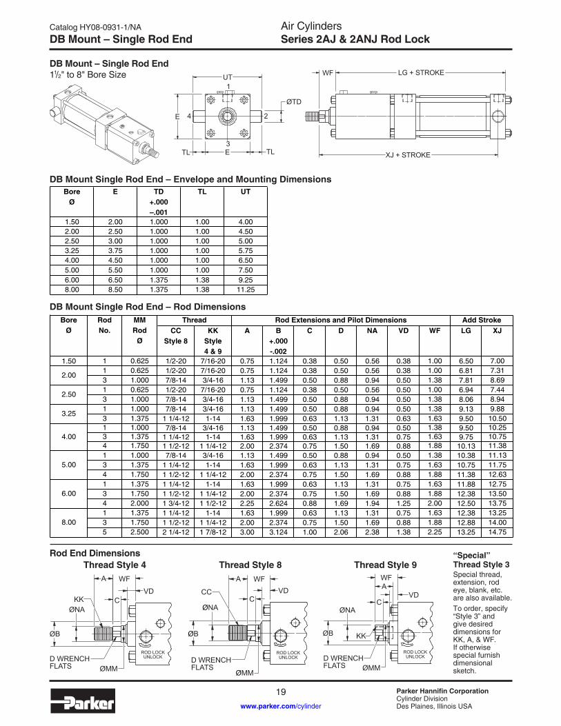
Air CylindersSeries 2AJ & 2ANJ Rod LockDB Mount – Single Rod End
DB Mount Single Rod End – Envelope and Mounting Dimensions
Rod End DimensionsThread Style 8 Thread Style 9Thread Style 4
“Special” Thread Style 3Special thread, extension, rod eye, blank, etc. are also available. To order, specify “Style 3” and give desired dimensions for KK, A, & WF. If otherwise special furnish dimensional sketch.
DB Mount Single Rod End – Rod Dimensions
DB Mount – Single Rod End 11/2" to 8" Bore Size
ØB
ØNA
ØMM
ROD LOCKUNLOCKD WRENCH
FLATS
WF
VD
A
CKK
ROD LOCKUNLOCKD WRENCH
FLATSØMM
ØB
ØNA
WFAVDCC
C
ROD LOCKUNLOCKD WRENCH
FLATS
WF
VD
ØB
ØNA
A
ØMM
C
KK
1
2
3
4
WF
E
ØTD
UT
TLTL E
LG + STROKE
XJ + STROKE
BoreØ
E TD +.000–.001
TL UT
1.50 2.00 1.000 1.00 4.002.00 2.50 1.000 1.00 4.502.50 3.00 1.000 1.00 5.003.25 3.75 1.000 1.00 5.754.00 4.50 1.000 1.00 6.505.00 5.50 1.000 1.00 7.506.00 6.50 1.375 1.38 9.258.00 8.50 1.375 1.38 11.25
1.50 1 0.625 1/2-20 7/16-20 0.75 1.124 0.38 0.50 0.56 0.38 1.00 6.50 7.001 0.625 1/2-20 7/16-20 0.75 1.124 0.38 0.50 0.56 0.38 1.00 6.81 7.313 1.000 7/8-14 3/4-16 1.13 1.499 0.50 0.88 0.94 0.50 1.38 7.81 8.691 0.625 1/2-20 7/16-20 0.75 1.124 0.38 0.50 0.56 0.50 1.00 6.94 7.443 1.000 7/8-14 3/4-16 1.13 1.499 0.50 0.88 0.94 0.50 1.38 8.06 8.941 1.000 7/8-14 3/4-16 1.13 1.499 0.50 0.88 0.94 0.50 1.38 9.13 9.883 1.375 1 1/4-12 1-14 1.63 1.999 0.63 1.13 1.31 0.63 1.63 9.50 10.501 1.000 7/8-14 3/4-16 1.13 1.499 0.50 0.88 0.94 0.50 1.38 9.50 10.253 1.375 1 1/4-12 1-14 1.63 1.999 0.63 1.13 1.31 0.75 1.63 9.75 10.754 1.750 1 1/2-12 1 1/4-12 2.00 2.374 0.75 1.50 1.69 0.88 1.88 10.13 11.381 1.000 7/8-14 3/4-16 1.13 1.499 0.50 0.88 0.94 0.50 1.38 10.38 11.133 1.375 1 1/4-12 1-14 1.63 1.999 0.63 1.13 1.31 0.75 1.63 10.75 11.754 1.750 1 1/2-12 1 1/4-12 2.00 2.374 0.75 1.50 1.69 0.88 1.88 11.38 12.631 1.375 1 1/4-12 1-14 1.63 1.999 0.63 1.13 1.31 0.75 1.63 11.88 12.753 1.750 1 1/2-12 1 1/4-12 2.00 2.374 0.75 1.50 1.69 0.88 1.88 12.38 13.504 2.000 1 3/4-12 1 1/2-12 2.25 2.624 0.88 1.69 1.94 1.25 2.00 12.50 13.751 1.375 1 1/4-12 1-14 1.63 1.999 0.63 1.13 1.31 0.75 1.63 12.38 13.253 1.750 1 1/2-12 1 1/4-12 2.00 2.374 0.75 1.50 1.69 0.88 1.88 12.88 14.005 2.500 2 1/4-12 1 7/8-12 3.00 3.124 1.00 2.06 2.38 1.38 2.25 13.25 14.75
C DBore
ØRodNo.
ThreadCC
Style 8KK
Style4 & 9
2.00
6.00
8.00
4.00
5.00
2.50
3.25
LGAdd Stroke
XJMMRod
ØNA
Rod Extensions and Pilot DimensionsVD WFA B
+.000-.002
Air CylindersSeries 2AJ & 2ANJ Rod Lock
Catalog HY08-0931-1/NA
20 Parker Hannifin CorporationCylinder DivisionDes Plaines, Illinois USAwww.parker.com/cylinder
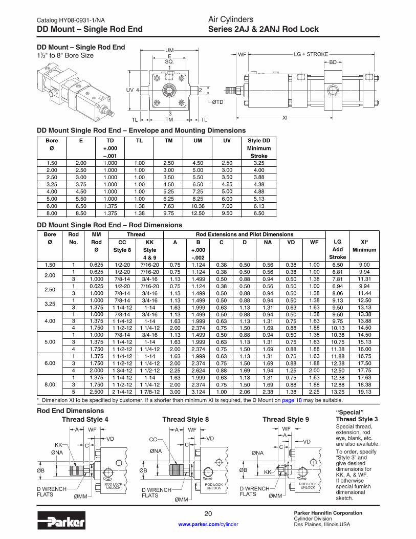
DD Mount – Single Rod End
DD Mount – Single Rod End 11/2" to 8" Bore Size
DD Mount Single Rod End – Envelope and Mounting Dimensions
Rod End DimensionsThread Style 8 Thread Style 9Thread Style 4
“Special” Thread Style 3Special thread, extension, rod eye, blank, etc. are also available. To order, specify “Style 3” and give desired dimensions for KK, A, & WF. If otherwise special furnish dimensional sketch.
DD Mount Single Rod End – Rod Dimensions
ØB
ØNA
ØMM
ROD LOCKUNLOCKD WRENCH
FLATS
WF
VD
A
CKK
ROD LOCKUNLOCKD WRENCH
FLATSØMM
ØB
ØNA
WFAVDCC
C
ROD LOCKUNLOCKD WRENCH
FLATS
WF
VD
ØB
ØNA
A
ØMM
C
KK
1
2
3
4
WF
UV
ESQ.
TM TL
ØTD
XI
BDLG + STROKE
UM
TL
BoreØ
E TD +.000–.001
TL TM UM UV Style DD Minimum
Stroke1.50 2.00 1.000 1.00 2.50 4.50 2.50 3.252.00 2.50 1.000 1.00 3.00 5.00 3.00 4.002.50 3.00 1.000 1.00 3.50 5.50 3.50 3.883.25 3.75 1.000 1.00 4.50 6.50 4.25 4.384.00 4.50 1.000 1.00 5.25 7.25 5.00 4.885.00 5.50 1.000 1.00 6.25 8.25 6.00 5.136.00 6.50 1.375 1.38 7.63 10.38 7.00 6.138.00 8.50 1.375 1.38 9.75 12.50 9.50 6.50
1.50 1 0.625 1/2-20 7/16-20 0.75 1.124 0.38 0.50 0.56 0.38 1.00 6.50 9.001 0.625 1/2-20 7/16-20 0.75 1.124 0.38 0.50 0.56 0.38 1.00 6.81 9.943 1.000 7/8-14 3/4-16 1.13 1.499 0.50 0.88 0.94 0.50 1.38 7.81 11.311 0.625 1/2-20 7/16-20 0.75 1.124 0.38 0.50 0.56 0.50 1.00 6.94 9.943 1.000 7/8-14 3/4-16 1.13 1.499 0.50 0.88 0.94 0.50 1.38 8.06 11.441 1.000 7/8-14 3/4-16 1.13 1.499 0.50 0.88 0.94 0.50 1.38 9.13 12.503 1.375 1 1/4-12 1-14 1.63 1.999 0.63 1.13 1.31 0.63 1.63 9.50 13.131 1.000 7/8-14 3/4-16 1.13 1.499 0.50 0.88 0.94 0.50 1.38 9.50 13.383 1.375 1 1/4-12 1-14 1.63 1.999 0.63 1.13 1.31 0.75 1.63 9.75 13.884 1.750 1 1/2-12 1 1/4-12 2.00 2.374 0.75 1.50 1.69 0.88 1.88 10.13 14.501 1.000 7/8-14 3/4-16 1.13 1.499 0.50 0.88 0.94 0.50 1.38 10.38 14.503 1.375 1 1/4-12 1-14 1.63 1.999 0.63 1.13 1.31 0.75 1.63 10.75 15.134 1.750 1 1/2-12 1 1/4-12 2.00 2.374 0.75 1.50 1.69 0.88 1.88 11.38 16.001 1.375 1 1/4-12 1-14 1.63 1.999 0.63 1.13 1.31 0.75 1.63 11.88 16.753 1.750 1 1/2-12 1 1/4-12 2.00 2.374 0.75 1.50 1.69 0.88 1.88 12.38 17.504 2.000 1 3/4-12 1 1/2-12 2.25 2.624 0.88 1.69 1.94 1.25 2.00 12.50 17.751 1.375 1 1/4-12 1-14 1.63 1.999 0.63 1.13 1.31 0.75 1.63 12.38 17.633 1.750 1 1/2-12 1 1/4-12 2.00 2.374 0.75 1.50 1.69 0.88 1.88 12.88 18.385 2.500 2 1/4-12 1 7/8-12 3.00 3.124 1.00 2.06 2.38 1.38 2.25 13.25 19.13
2.00
6.00
8.00
4.00
5.00
2.50
3.25
BoreØ
RodNo.
ThreadCC
Style 8KK
Style4 & 9
MMRod
ØLGAdd
Stroke
XI*Minimum
C D NARod Extensions and Pilot Dimensions
VD WFA B +.000-.002
* Dimension XI to be specified by customer. If a shorter than minimum XI is required, the D Mount on page 18 may be suitable.

Catalog HY08-0931-1/NA
21 Parker Hannifin CorporationCylinder DivisionDes Plaines, Illinois USAwww.parker.com/cylinder
Air CylindersSeries 2AJ & 2ANJ Rod LockDouble Rod Cylinder Dimension Drawings
How to Use Double Rod Cylinder Dimension DrawingsTo determine dimensions for a double rod cylinder, first refer to the desired single rod mounting style cylindershown on preceding pages of this catalog. After selecting necessary dimensions from that drawing, return to this page and supplement the single rod dimensions with those shown in the drawings and dimension table below. Note that double rod cylinders have a head (Dim. G) at both ends and that dimension LD replaces LG.
The double rod dimensions differ from, or are in addition to those for single rod cylinders shown on preceding pages and provide the information needed to completely dimension a double rod cylinder.
On a double rod cylinder, where the two rod ends are different, be sure to clearly state which rod end is to beassembled at which end. Port position #1 is standard. If other than standard, specify port position #2, 3 or 4 asviewed from one end only.
11/2" to 6" Bores
Mounting Styles for Single Rod
Models
CorrespondingMounting Stylesfor Double Rod
Models
T KT
TB KTB
TD KTD
J KJ
C KC
F KF
D KD
DD KDD
EEP + STROKE
ZM + 2 X STROKE
ROD END #1 ROD END #2
ØMM
G G F
LD + STROKE
Y
8" BoreP + STROKE
G G F
ZM + 2 X STROKE
Y
LD + STROKE
EE
ØMM
ROD END #2ROD END #1
Add 2X Stroke
LD SSK ZM1.50 1 0.625 3/8 0.38 1.50 2.25 4.81 7.38 2.88 9.00
1 0.625 3/8 0.38 1.50 2.25 5.13 7.69 2.88 9.313 1.000 3/8 0.38 1.50 2.25 6.50 8.69 2.88 11.061 0.625 3/8 0.38 1.50 2.38 5.13 7.81 3.00 9.443 1.000 3/8 0.38 1.50 2.38 6.63 8.94 3.00 11.311 1.000 1/2 0.63 1.75 2.63 7.31 10.25 3.25 12.383 1.375 1/2 0.63 1.75 2.63 7.94 10.63 3.25 13.251 1.000 1/2 0.63 1.75 2.63 7.69 10.63 3.25 12.753 1.375 1/2 0.63 1.75 2.63 8.19 10.88 3.25 13.504 1.750 1/2 0.63 1.75 2.63 8.81 11.25 3.25 14.381 1.000 1/2 0.63 1.75 2.88 8.31 11.50 3.13 13.633 1.375 1/2 0.63 1.75 2.88 8.94 11.88 3.13 14.504 1.750 1/2 0.63 1.75 2.88 9.81 12.50 3.13 15.631 1.375 3/4 0.75 2.00 3.13 9.69 13.13 3.63 15.633 1.750 3/4 0.75 2.00 3.13 10.44 13.63 3.63 16.634 2.000 3/4 0.75 2.00 3.13 10.69 13.75 3.63 17.001 1.375 3/4 0.75 2.00 3.25 10.06 13.63 3.75 16.133 1.750 3/4 0.75 2.00 3.25 10.81 14.13 3.75 17.135 2.500 3/4 0.75 2.00 3.25 11.56 14.50 3.75 18.25
SSC
Replaces DimensionOn Single Rod Mounting Style
2.00
6.00
8.00
4.00
5.00
2.50
3.25
BoreØ
RodNo.
MMRod
Ø
FEENPTF
YG P Add Stroke

Air CylindersSeries 2AJ & 2ANJ Rod Lock
Catalog HY08-0931-1/NA
22 Parker Hannifin CorporationCylinder DivisionDes Plaines, Illinois USAwww.parker.com/cylinder
Style 55 / Split Flange Coupler / Weld Plates
Parker Style “55” Flange Coupling Piston Rod End• Simplifies alignment• Reduces assembly time• Allows full rated pneumatic pressure in push and
pull directions• Available 5/8" through 2 1/2" piston rod diameters
How to OrderWhen preparing the Model Code enter a 55 in the Piston Rod Thread Style position.
Example: 2.50 J2AJLU155 X 8.00
AD
AE
ØAF
ØAM
WG
ØMM
ROD LOCKUNLOCK
Split Couplers and Weld Plates
WARNING: Piston rod separation from the machine member can result in severe personal injury or even death to nearby personnel. The cylinder user must make sure the weld holding the weld plate to the machine is of sufficient quality and size to hold the intended load. The cylinder user must also make sure the bolts holding split coupler to the weld plate are of sufficient strength to hold the intended load and installed in such a way that they will not become loose during the machine’s operation.
ØE
C DF BOLTS
ØA
ØB
STYLE 55 ROD ENDSPLIT COUPLER
WELD PLATE
0.625 0.63 0.25 0.38 0.57 1.751.000 0.94 0.38 0.69 0.95 2.381.375 1.06 0.38 0.88 1.32 2.751.750 1.31 0.50 1.13 1.70 3.132.000 1.69 0.63 1.38 1.95 3.752.500 1.94 0.75 1.75 2.45 4.50
MMRod
Ø
AD AE AF AM WG
Style 55 Rod End Dimensions
Dimensions and Part Numbers
0.625 1.50 2.00 0.50 0.56 0.25 4 #10-24 x 0.94 LG 1.13 1472340062 14817400621.000 2.00 2.50 0.50 0.88 0.25 6 1/4-20 x 1.25 LG 1.50 1472340100 14817401001.375 2.50 3.00 0.63 1.00 0.25 6 5/16-18 x 1.50 LG 2.00 1472340138 14817401381.750 3.00 4.00 0.63 1.25 0.25 8 5/16-18 x 1.75 LG 2.38 1472340175 14817401752.000 3.50 4.00 0.75 1.63 0.38 12 3/8-16 x 2.25 LG 2.69 1472340200 14817402002.500 4.00 4.50 0.75 1.88 0.38 12 3/8-16 x 2.50 LG 3.19 1472340250 1481740250
MMRod
Ø
A B C D E Weld PlatePart Number
F Bolt Size Bolt Circle
Split Coupler Part Number

Catalog HY08-0931-1/NA
23 Parker Hannifin CorporationCylinder DivisionDes Plaines, Illinois USAwww.parker.com/cylinder
Air CylindersSeries 2AJ & 2ANJ Rod LockAccessories for Mounting Style SB
Accessories for Mounting Style SBAccessories for mounting SB include Rod Eye, Pivot Pin and Clevis Bracket. To select the proper part number for any desired accessory refer to the charts below.
Spherical Rod Eye
Order to fit Piston Rod Thread Size.
LE
CD
JKTHD
ER (MAX)
LUBEFITTINGCE
A
EX
JL DIA
Pivot Pin
Pivot Pins are furnished with (2) Retainer Rings.
Clevis Bracket
Order to fit Mounting Plate or Rod Eye.
Bore Size Series 2AJ 11/2, 2 & 21/2 31/4, 4 & 5 6 & 8Rod Eye Part No. 1322900000 1322910000 1322920000
CD .5000 -.0005 .7500 -.0005 1.0000 -.0005
A 11/16 1 11/2
CE 7/8 11/4 17/8
EX 7/1621/32
7/8
ER 13/16 11/8 11/4LE 3/4 11/16 17/16
JK 7/16 -20 3/4 -16 1-14JL 7/8 15/16 11/2
LOADCAPACITY
LBS.2644 9441 16860
CL
CD
Bore Size Series 2AJ 11/2, 2 & 21/2 31/4, 4 & 5 6 & 8Pivot Pin Part No. 0839620000 0839630000 0839640000
CD .4997 -.0004 .7497 -.0005 .9997 -.0005
CL 19/16 21/32 21/2
LOADCAPACITY
LBS.8600 19300 34300
MR
LR
RE
DD DIA4 HOLES
F
M
FL
CW CWCF
+ .004+ .002
RE
CD
Bore Size Series 2AJ 11/2, 2 & 21/2 31/4, 4 & 5 6 & 8Clevis Bracket Part No. 0839470000 0839480000 0839490000
CD 1/23/4 1
CF 7/1621/32
7/8
CW 1/25/8
3/4DD 13/32
17/3217/32
E 3 33/4 51/2F 1/2
5/83/4
FL 11/2 2 21/2
LR 15/16 13/8 111/16
M 1/27/8 1
MR 5/8 1 13/16
R 2.05 2.76 4.10 LOAD
CAPACITYLBS.
5770 9450 14300
Air CylindersSeries 2AJ & 2ANJ Rod Lock
Catalog HY08-0931-1/NA
24 Parker Hannifin CorporationCylinder DivisionDes Plaines, Illinois USAwww.parker.com/cylinder
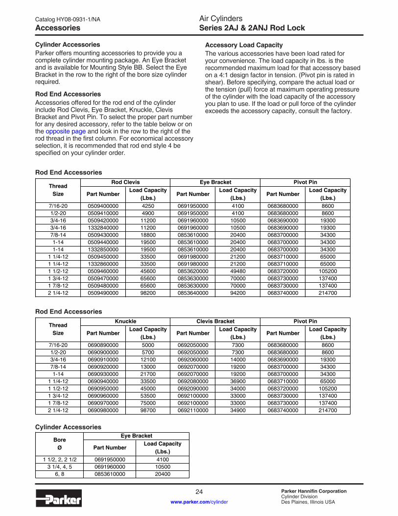
Accessories
Cylinder AccessoriesParker offers mounting accessories to provide you a complete cylinder mounting package. An Eye Bracket and is available for Mounting Style BB. Select the Eye Bracket in the row to the right of the bore size cylinder required.
Rod End AccessoriesAccessories offered for the rod end of the cylinder include Rod Clevis, Eye Bracket, Knuckle, Clevis Bracket and Pivot Pin. To select the proper part number for any desired accessory, refer to the table below or on the opposite page and look in the row to the right of the rod thread in the first column. For economical accessory selection, it is recommended that rod end style 4 be specified on your cylinder order.
Accessory Load CapacityThe various accessories have been load rated for your convenience. The load capacity in lbs. is the recommended maximum load for that accessory based on a 4:1 design factor in tension. (Pivot pin is rated in shear). Before specifying, compare the actual load or the tension (pull) force at maximum operating pressure of the cylinder with the load capacity of the accessory you plan to use. If the load or pull force of the cylinder exceeds the accessory capacity, consult the factory.
Rod End Accessories
7/16-20 0509400000 4250 0691950000 4100 0683680000 86001/2-20 0509410000 4900 0691950000 4100 0683680000 86003/4-16 0509420000 11200 0691960000 10500 0683690000 193003/4-16 1332840000 11200 0691960000 10500 0683690000 193007/8-14 0509430000 18800 0853610000 20400 0683700000 343001-14 0509440000 19500 0853610000 20400 0683700000 343001-14 1332850000 19500 0853610000 20400 0683700000 34300
1 1/4-12 0509450000 33500 0691980000 21200 0683710000 650001 1/4-12 1332860000 33500 0691980000 21200 0683710000 650001 1/2-12 0509460000 45600 0853620000 49480 0683720000 1052001 3/4-12 0509470000 65600 0853630000 70000 0683730000 1374001 7/8-12 0509480000 65600 0853630000 70000 0683730000 1374002 1/4-12 0509490000 98200 0853640000 94200 0683740000 214700
ThreadSize Part Number
Load Capacity(Lbs.)
Rod Clevis Eye Bracket
Part NumberLoad Capacity
(Lbs.)
Pivot Pin
Part NumberLoad Capacity
(Lbs.)
Cylinder Accessories
1 1/2, 2, 2 1/2 0691950000 41003 1/4, 4, 5 0691960000 10500
6, 8 0853610000 20400
BoreØ
Eye Bracket
Part NumberLoad Capacity
(Lbs.)
Rod End Accessories
7/16-20 0690890000 5000 0692050000 7300 0683680000 86001/2-20 0690900000 5700 0692050000 7300 0683680000 86003/4-16 0690910000 12100 0692060000 14000 0683690000 193007/8-14 0690920000 13000 0692070000 19200 0683700000 343001-14 0690930000 21700 0692070000 19200 0683700000 34300
1 1/4-12 0690940000 33500 0692080000 36900 0683710000 650001 1/2-12 0690950000 45000 0692090000 34000 0683720000 1052001 3/4-12 0690960000 53500 0692100000 33000 0683730000 1374001 7/8-12 0690970000 75000 0692100000 33000 0683730000 1374002 1/4-12 0690980000 98700 0692110000 34900 0683740000 214700
ThreadSize
Knuckle Clevis Bracket Pivot Pin
Part NumberLoad Capacity
(Lbs.)Part Number
Load Capacity(Lbs.)
Part NumberLoad Capacity
(Lbs.)

Catalog HY08-0931-1/NA
25 Parker Hannifin CorporationCylinder DivisionDes Plaines, Illinois USAwww.parker.com/cylinder
Air CylindersSeries 2AJ & 2ANJ Rod LockAccessories
Rod Clevis DimensionsCBCW CW
ER
KK THREAD
+.004+.002CD
A
CE
Pivot Pin Dimensions
CL
CD +.001 -.002
Part Number CD CL0683680000 1/2 1 7/80683690000 3/4 2 5/80683700000 1 3 1/80683710000 1 3/8 4 1/80683720000 1 3/4 5 3/160683730000 2 5 3/160683740000 2 1/2 6 3/16
Eye Bracket Dimensions
MR
LR
RE
DD DIA4 HOLES
F
M 25°
FL
CB
+ .004+ .002
RE
CD
Part Number CB CD DD E F FL LR M MR R0691950000 3/4 1/2 13/32 2 1/2 3/8 1 1/8 3/4 1/2 9/16 1.630691960000 1 1/4 3/4 17/32 3 1/2 5/8 1 7/8 1 1/4 3/4 7/8 2.550853610000 1 1/2 1 21/32 4 1/2 7/8 2 3/8 1 1/2 1 1 1/4 3.250691980000 2 1 3/8 21/32 5 7/8 3 2 1/8 1 3/8 1 5/8 3.820853620000 2 1/2 1 3/4 29/32 6 1/2 1 1/8 3 3/8 2 1/4 1 3/4 2 1/8 4.950853630000 2 1/2 2 1 1/16 7 1/2 1 1/2 4 2 1/2 2 2 7/16 5.730853640000 3 2 1/2 1 3/16 8 1/2 1 3/4 4 3/4 3 2 1/2 3 6.58
Clevis Bracket Dimensions
25°MR
LR
RE
DD DIA4 HOLES
F
M
FL
CW CWCB
+ .004+ .002
RE
CD
Part Number CB CD CW DD E F FL LR M MR R0692050000 3/4 1/2 1/2 13/32 3 1/2 1/2 1 1/2 3/4 1/2 5/8 2.550692060000 1 1/4 3/4 5/8 17/32 5 5/8 1 7/8 1 3/16 3/4 29/32 3.820692070000 1 1/2 1 3/4 21/32 6 1/2 3/4 2 1/4 1 1/2 1 1 1/4 4.950692080000 2 1 3/8 1 21/32 7 1/2 7/8 3 2 1 3/8 1 21/32 5.730692090000 2 1/2 1 3/4 1 1/4 29/32 9 1/2 7/8 3 5/8 2 3/4 1 3/4 2 7/32 7.500692100000 2 1/2 2 1 1/2 1 1/16 12 3/4 1 4 1/4 3 3/16 2 1/4 2 25/32 9.400692110000 3 2 1/2 1 1/2 1 3/16 12 3/4 1 4 1/2 3 1/2 2 1/2 3 1/8 9.40
1. Pivot Pins are furnished with (2) retainer rings.2. Pivot Pins must be ordered as a separate item if to be used with Rod Clevises or Clevis Brackets.
Part Number A CB CD CE CW ER KK0509400000 3/4 3/4 1/2 1 1/2 1/2 1/2 7/16-200509410000 3/4 3/4 1/2 1 1/2 1/2 1/2 1/2-200509420000 1 1/8 1 1/4 3/4 2 1/8 5/8 3/4 3/4-161332840000 1 1/8 1 1/4 3/4 2 3/8 5/8 3/4 3/4-160509430000 1 5/8 1 1/2 1 2 15/16 3/4 1 7/8-140509440000 1 5/8 1 1/2 1 2 15/16 3/4 1 1-141332850000 1 5/8 1 1/2 1 3 1/8 3/4 1 1-140509450000 1 7/8 2 1 3/8 3 3/4 1 1 3/8 1 1/4-121332860000 2 2 1 3/8 4 1/8 1 1 3/8 1 1/4-120509460000 2 1/4 2 1/2 1 3/4 4 1/2 1 1/4 1 3/4 1 1/2-120509470000 3 2 1/2 2 5 1/2 1 1/4 2 1 3/4-120509480000 3 2 1/2 2 5 1/2 1 1/4 2 1 7/8-120509490000 3 1/2 3 2 1/2 6 1/2 1 1/2 2 1/2 2 1/4-12
Knuckle Dimensions
CB
CDER +.004+.002
CD CA
CD
CDKK THREAD
A FULLTHREAD
Part Number A CA CB0690890000 3/4 1 1/2 3/40690900000 3/4 1 1/2 3/40690910000 1 1/8 2 1/16 1 1/40690920000 1 1/8 2 3/8 1 1/20690930000 1 5/8 2 13/16 1 1/20690940000 2 3 7/16 20690950000 2 1/4 4 2 1/20690960000 2 1/4 4 3/8 2 1/20690970000 3 5 2 1/20690980000 3 1/2 5 13/16 3
Part Number CD ER KK0690890000 1/2 23/32 7/16-200690900000 1/2 23/32 1/2-200690910000 3/4 1 1/16 3/4-160690920000 1 1 7/16 7/8-140690930000 1 1 7/16 1-140690940000 1 3/8 1 31/32 1 1/4-120690950000 1 3/4 2 1/2 1 1/2-120690960000 2 2 27/32 1 3/4-120690970000 2 2 27/32 1 7/8-120690980000 2 1/2 3 9/16 2 1/4-12

Air CylindersSeries 2AJ & 2ANJ Rod Lock
Catalog HY08-0931-1/NA
26 Parker Hannifin CorporationCylinder DivisionDes Plaines, Illinois USAwww.parker.com/cylinder
Rod Lock Removal & Installation
Rod Lock RemovalTo service the base 2AJ or 2ANJ cylinder the Rod Lock must first be removed.
Note: The Rod Lock cannot be serviced nor is it considered a service item. The 2AJ or 2ANJ cylinder must be returned to the factory for Rod Lock service.
1. Using a corner-to-corner sequence, remove the four hex tie rod nuts at the face of the Rod Lock.
2. Apply a minimum of 60 psi to the Rod Lock release port, or apply the appropriate torque to the manual override shaft to disengage the Rod Lock from the piston rod.
3. Carefully slide the Rod Lock off the cylinder. The Rod Lock is piloted and sealed to the gland OD which may necessitate carefully prying the unit from the gland retainer.
4. The 2AJ or 2ANJ cylinder can now be serviced per normal practice. See the following page for cylinder service kits.
Rod Lock Installation1. Ensure that the mating surfaces of the Rod Lock and
cylinder are free of dirt and debris.2. Apply a minimum of 60 psi to the Rod Lock release
port, or apply the appropriate torque to the manual override shaft to disengage the Rod Lock from the piston rod.
3. Carefully slide the rod lock onto the piston rod toward the base cylinder. Because the Rod Lock is sealed to the gland some force may be required to bring it in contact with the gland retainer. Take care not to damage to Rod Lock-to-gland o-ring seal.
4. Torque the hex tie rod nuts that secure the Rod Lock to the values in the table below. Be sure to reuse nuts supplied with the cylinder. Torque the nuts gradually, starting at one corner and work in a diagonal pattern to ensure evenness of tightening. DO NOT TORQUE ONE NUT COMPLETELY AND THEN THE OTHERS.
5. Remove air pressure from the Rod Lock release port or torque from the manual override release shaft to engage the Rod Lock.
1.50 60 – 70 in.-lbs. 69 – 81 cm-kg2.00 11 – 12 ft.-lbs. 15 – 16 N-m2.50 11 – 12 ft.-lbs. 15 – 16 N-m3.25 25 – 26 ft.-lbs. 34 – 35 N-m4.00 25 – 26 ft.-lbs. 34 – 35 N-m5.00 60 – 64 ft.-lbs. 81 – 87 N-m6.00 60 – 64 ft.-lbs. 81 – 87 N-m8.00 110 – 114 ft.-lbs. 149 – 155 N-m
BoreØ
Tie Rod Torque

Catalog HY08-0931-1/NA
27 Parker Hannifin CorporationCylinder DivisionDes Plaines, Illinois USAwww.parker.com/cylinder
Air CylindersSeries 2AJ & 2ANJ Rod LockParts Identification / Service Kits
1.50" through 8.00" Bore Sizes
Symbol Description 14 Rod Gland 40 Rod Wiper 41 Rod Seal 42 Piston Lipseal 43* Rod Seal Back-up Washer 44* Piston Seal Back-up Washer 45 Gland to Head O-ring 47 End Seal O-ring 121 Piston Wear Ring
1440
41 43
45
47 42 44 47
Lipseal Piston with Wear Ring 8" Bore
*Item not required in Series 2ANJ
42 4244 44121
Rod Gland & Rod Seal Kits
0.625 RG2AJ00061 RK2AJ00061 RG2AJ00065 RK2AJ00065 RG2ANJ0061 RK2ANJ00611.000 RG2AJ00101 RK2AJ00101 RG2AJ00105 RK2AJ00105 RG2ANJ0101 RK2ANJ01011.375 RG2AJ00131 RK2AJ00131 RG2AJ00135 RK2AJ00135 RG2ANJ0131 RK2ANJ01311.750 RG2AJ00171 RK2AJ00171 RG2AJ00175 RK2AJ00175 RG2ANJ0171 RK2AN001712.000 RG2AJ00201 RK2AJ00201 RG2AJ00205 RK2AJ00205 RG2ANJ0201 RK2ANJ02012.500 RG2AJ00251 RK2AJ00251 RG2AJ00255 RK2AJ00255 RG2ANJ0251 RK2ANJ0251
RodØ
Series 2AJ
Gland Cartridge Kits (Contains: 1 Each Sym.# 14, 40, 41, 43, & 45)
Rod Seal Kits(Contains: 1 Each Sym.
# 40, 41, 43, & 45)
Class 1 Class 5Gland Cartridge Kits
(Contains: 1 Each Sym.# 14, 40, 41, 43, & 45)
Rod Seal Kits(Contains: 1 Each Sym.
# 40, 41, 43, & 45)
Series 2ANJ
Gland Cartridge Kits (Contains: 1 Each Sym.
# 14, 40, 41, & 45)
Rod Seal Kits(Contains: 1 Each Sym.
# 40, 41, & 45)
Class 1
Piston Seal KitsSeries 2ANJ
Class 1 Class 5 Class 11.500 PK1502A001 PK1502A005 PK1502AN012.000 PK2002A001 PK2002A005 PK2002AN012.500 PK2502A001 PK2502A005 PK2502AN013.250 PK3202A001 PK3202A005 PK3202AN014.000 PK4002A001 PK4002A005 PK4002AN015.000 PK5002A001 PK5002A005 PK5002AN016.000 PK6002A001 PK6002A005 PK6002AN018.000 PK8002A001 PK8002A005 PK8002AN01
Piston Seal Kits(Contains: Each Sym.
# 42 & 47)
BoreØ Piston Seal Kits
(Contains: Each Sym. # 42, 44 & 47)
Series 2AJ
Note: Class 5 seals do not increase temperature resistance of the cylinder and rod lock assemblySpecify Class 5 seals only for chemical compatibility.

Air CylindersSeries 2AJ & 2ANJ Rod Lock
Catalog HY08-0931-1/NA
28 Parker Hannifin CorporationCylinder DivisionDes Plaines, Illinois USAwww.parker.com/cylinder
Cylinder Safety Guide
Before selecting or using Parker (The Company) cylinders or related accessories, it is important that you read, understand and follow the following safety informa-tion. Training is advised before selecting and using The Company’s products.
1.0 General Instructions 1.1 Scope – This safety guide provides instructions for selecting and using
(including assembling, installing, and maintaining) cylinder products. This safety guide is a supplement to and is to be used with the specific Company publications for the specific cylinder products that are being considered for use.
1.2 Fail Safe – Cylinder products can and do fail without warning for many reasons. All systems and equipment should be designed in a fail-safe mode so that if the failure of a cylinder product occurs people and property won’t be endangered.
1.3 Distribution – Provide a free copy of this safety guide to each person responsible for selecting or using cylinder products. Do not select or use The Company’s cylinders without thoroughly reading and understanding this safety guide as well as the specific Company publications for the products considered or selected.
1.4 User Responsibility – Due to very wide variety of cylinder applications and cylinder operating conditions, The Company does not warrant that any particular cylinder is suitable for any specific application. This safety guide does not analyze all technical parameters that must be considered in select-ing a product. The hydraulic and pneumatic cylinders outlined in this catalog are designed to The Company’s design guidelines and do not necessarily meet the design guideline of other agencies such as American Bureau of Shipping, ASME Pressure Vessel Code etc. The user, through its own analysis and testing, is solely responsible for:
• Making the final selection of the cylinders and related accessories. • Determining if the cylinders are required to meet specific design require-
ments as required by the Agency(s) or industry standards covering the design of the user’s equipment.
• Assuring that the user’s requirements are met, OSHA requirements are met, and safety guidelines from the applicable agencies such as but not limited to ANSI are followed and that the use presents no health or safety hazards.
• Providing all appropriate health and safety warnings on the equipment on which the cylinders are used.
1.5 Additional Questions – Call the appropriate Company technical service department if you have any questions or require any additional information. See the Company publication for the product being considered or used, or call 1-847-298-2400, or go to www.parker.com, for telephone numbers of the appropriate technical service department.
2.0 Cylinder and Accessories Selection 2.1 Seals – Part of the process of selecting a cylinder is the selection of
seal compounds. Before making this selection, consult the “seal information page(s)” of the publication for the series of cylinders of interest.
The application of cylinders may allow fluids such as cutting fluids, wash down fluids etc. to come in contact with the external area of the cylinder. These fluids may attack the piston rod wiper and or the primary seal and must be taken into account when selecting and specifying seal compounds.
Dynamic seals will wear. The rate of wear will depend on many operating factors. Wear can be rapid if a cylinder is mis-aligned or if the cylinder has been improperly serviced. The user must take seal wear into consideration in the application of cylinders.
2.2 Piston Rods – Possible consequences of piston rod failure or separation of the piston rod from the piston include, but are not limited to are:
• Piston rod and or attached load thrown off at high speed. • High velocity fluid discharge. • Piston rod extending when pressure is applied in the piston
retract mode.
Piston rods or machine members attached to the piston rod may move suddenly and without warning as a consequence of other conditions occurring to the machine such as, but not limited to:
• Unexpected detachment of the machine member from the piston rod.
• Failure of the pressurized fluid delivery system (hoses, fittings, valves, pumps, compressors) which maintain cylinder position.
• Catastrophic cylinder seal failure leading to sudden loss of pressurized fluid.
• Failure of the machine control system. Follow the recommendations of the “Piston Rod Selection Chart and Data”
in the publication for the series of cylinders of interest. The suggested piston rod diameter in these charts must be followed in order to avoid piston rod buckling.
Piston rods are not normally designed to absorb bending moments or loads which are perpendicular to the axis of piston rod motion. These additional loads can cause the piston rod to fail. If these types of additional loads are expected to be imposed on the piston rod, their magnitude should be made known to our engineering department.
The cylinder user should always make sure that the piston rod is securely attached to the machine member.
On occasion cylinders are ordered with double rods (a piston rod extended from both ends of the cylinder). In some cases a stop is threaded on to one of the piston rods and used as an external stroke adjuster. On occasions spacers are attached to the machine member connected to the piston rod and also used as a stroke adjuster. In both cases the stops will create a pinch point and the user should consider appropriate use of guards. If these external stops are not perpendicular to the mating contact surface, or if debris is trapped between the contact surfaces, a bending moment will be placed on the piston rod, which can lead to piston rod failure. An external stop will also negate the effect of cushioning and will subject the piston rod to impact loading. Those two (2) conditions can cause piston rod failure. Internal stroke adjusters are available with and without cushions. The use of external stroke adjusters should be reviewed with our engineering department.
The piston rod to piston and the stud to piston rod threaded connections are secured with an anaerobic adhesive. The strength of the adhesive decreases with increasing temperature. Cylinders which can be exposed to tempera-tures above +250°F (+121°C) are to be ordered with a non studded piston rod and a pinned piston to rod joint.
2.3 Cushions – Cushions should be considered for cylinder applications when the piston velocity is expected to be over 4 inches/second.
Cylinder cushions are normally designed to absorb the energy of a linear applied load. A rotating mass has considerably more energy than the same mass moving in a linear mode. Cushioning for a rotating mass application should be review by our engineering department.
2.4 Cylinder Mountings – Some cylinder mounting configurations may have certain limitations such as but not limited to minimum stroke for side or foot mounting cylinders or pressure de-ratings for certain mounts. Carefully review the catalog for these types of restrictions.
Always mount cylinders using the largest possible high tensile alloy steel socket head cap screws that can fit in the cylinder mounting holes and torque them to the manufacturer’s recommendations for their size.
2.5 Port Fittings – Hydraulic cylinders applied with meter out or decelera-tion circuits are subject to intensified pressure at piston rod end.
The rod end pressure is approximately equal to:
operating pressure x effective cap end area effective rod end piston area
Contact your connector supplier for the pressure rating of individual connectors.
3.0 Cylinder and Accessories Installation and Mounting 3.1 Installation 3.1.1 – Cleanliness is an important consideration, and cylinders are
shipped with the ports plugged to protect them from contaminants enter-ing the ports. These plugs should not be removed until the piping is to be installed. Before making the connection to the cylinder ports, piping should be thoroughly cleaned to remove all chips or burrs which might have resulted from threading or flaring operations.
Safety Guide for Selecting and Using Hydraulic, Pneumatic Cylinders and Their Accessories
WARNING: FAILURE OF THE CYLINDER, ITS PARTS, ITS MOUNTING, ITS CONNECTIONS TO OTHER OBJECTS, OR ITS CONTROLS CAN RESULT IN: • Unanticipated or uncontrolled movement of the cylinder or objects connected to it. • Falling of the cylinder or objects held up by it. • Fluid escaping from the cylinder, potentially at high velocity.THESE EvENTS COULD CAUSE DEATH OR PERSONAL INJURY BY, FOR EXAMPLE, PERSONS FALLING FROM HIGH LOCATIONS, BEING CRUSHED OR STRUCK BY HEAvY OR FAST MOvING OBJECTS, BEING PUSHED INTO DANGEROUS EQUIPMENT OR SITUATIONS, OR SLIPPING ON ESCAPED FLUID.
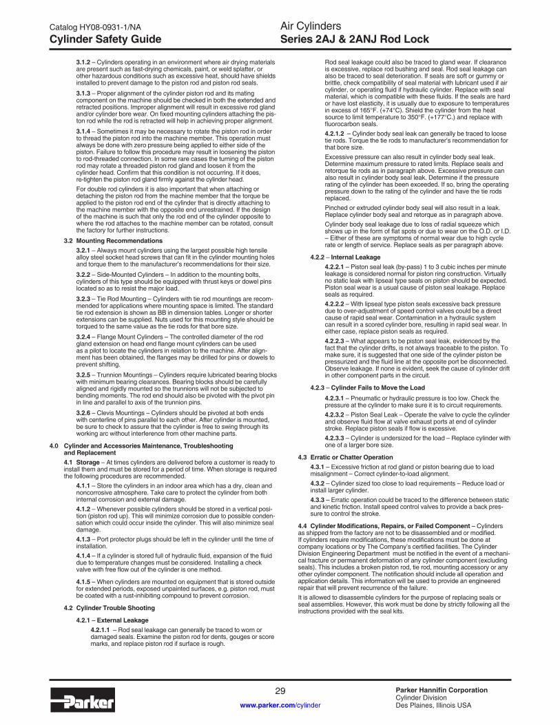
Catalog HY08-0931-1/NA
29 Parker Hannifin CorporationCylinder DivisionDes Plaines, Illinois USAwww.parker.com/cylinder
Air CylindersSeries 2AJ & 2ANJ Rod LockCylinder Safety Guide
3.1.2 – Cylinders operating in an environment where air drying materials are present such as fast-drying chemicals, paint, or weld splatter, or other hazardous conditions such as excessive heat, should have shields installed to prevent damage to the piston rod and piston rod seals.
3.1.3 – Proper alignment of the cylinder piston rod and its mating component on the machine should be checked in both the extended and retracted positions. Improper alignment will result in excessive rod gland and/or cylinder bore wear. On fixed mounting cylinders attaching the pis-ton rod while the rod is retracted will help in achieving proper alignment.
3.1.4 – Sometimes it may be necessary to rotate the piston rod in order to thread the piston rod into the machine member. This operation must always be done with zero pressure being applied to either side of the piston. Failure to follow this procedure may result in loosening the piston to rod-threaded connection. In some rare cases the turning of the piston rod may rotate a threaded piston rod gland and loosen it from the cylinder head. Confirm that this condition is not occurring. If it does, re-tighten the piston rod gland firmly against the cylinder head.
For double rod cylinders it is also important that when attaching or detaching the piston rod from the machine member that the torque be applied to the piston rod end of the cylinder that is directly attaching to the machine member with the opposite end unrestrained. If the design of the machine is such that only the rod end of the cylinder opposite to where the rod attaches to the machine member can be rotated, consult the factory for further instructions.
3.2 Mounting Recommendations 3.2.1 – Always mount cylinders using the largest possible high tensile
alloy steel socket head screws that can fit in the cylinder mounting holes and torque them to the manufacturer’s recommendations for their size.
3.2.2 – Side-Mounted Cylinders – In addition to the mounting bolts, cylinders of this type should be equipped with thrust keys or dowel pins located so as to resist the major load.
3.2.3 – Tie Rod Mounting – Cylinders with tie rod mountings are recom-mended for applications where mounting space is limited. The standard tie rod extension is shown as BB in dimension tables. Longer or shorter extensions can be supplied. Nuts used for this mounting style should be torqued to the same value as the tie rods for that bore size.
3.2.4 – Flange Mount Cylinders – The controlled diameter of the rod gland extension on head end flange mount cylinders can be used as a pilot to locate the cylinders in relation to the machine. After align-ment has been obtained, the flanges may be drilled for pins or dowels to prevent shifting.
3.2.5 – Trunnion Mountings – Cylinders require lubricated bearing blocks with minimum bearing clearances. Bearing blocks should be carefully aligned and rigidly mounted so the trunnions will not be subjected to bending moments. The rod end should also be pivoted with the pivot pin in line and parallel to axis of the trunnion pins.
3.2.6 – Clevis Mountings – Cylinders should be pivoted at both ends with centerline of pins parallel to each other. After cylinder is mounted, be sure to check to assure that the cylinder is free to swing through its working arc without interference from other machine parts.
4.0 Cylinder and Accessories Maintenance, Troubleshooting and Replacement
4.1 Storage – At times cylinders are delivered before a customer is ready to install them and must be stored for a period of time. When storage is required the following procedures are recommended.
4.1.1 – Store the cylinders in an indoor area which has a dry, clean and noncorrosive atmosphere. Take care to protect the cylinder from both internal corrosion and external damage.
4.1.2 – Whenever possible cylinders should be stored in a vertical posi-tion (piston rod up). This will minimize corrosion due to possible conden-sation which could occur inside the cylinder. This will also minimize seal damage.
4.1.3 – Port protector plugs should be left in the cylinder until the time of installation.
4.1.4 – If a cylinder is stored full of hydraulic fluid, expansion of the fluid due to temperature changes must be considered. Installing a check valve with free flow out of the cylinder is one method.
4.1.5 – When cylinders are mounted on equipment that is stored outside for extended periods, exposed unpainted surfaces, e.g. piston rod, must be coated with a rust-inhibiting compound to prevent corrosion.
4.2 Cylinder Trouble Shooting
4.2.1 – External Leakage 4.2.1.1 – Rod seal leakage can generally be traced to worn or
damaged seals. Examine the piston rod for dents, gouges or score marks, and replace piston rod if surface is rough.
Rod seal leakage could also be traced to gland wear. If clearance is excessive, replace rod bushing and seal. Rod seal leakage can also be traced to seal deterioration. If seals are soft or gummy or brittle, check compatibility of seal material with lubricant used if air cylinder, or operating fluid if hydraulic cylinder. Replace with seal material, which is compatible with these fluids. If the seals are hard or have lost elasticity, it is usually due to exposure to temperatures in excess of 165°F. (+74°C). Shield the cylinder from the heat source to limit temperature to 350°F. (+177°C.) and replace with fluorocarbon seals.
4.2.1.2 – Cylinder body seal leak can generally be traced to loose tie rods. Torque the tie rods to manufacturer’s recommendation for that bore size.
Excessive pressure can also result in cylinder body seal leak. Determine maximum pressure to rated limits. Replace seals and retorque tie rods as in paragraph above. Excessive pressure can also result in cylinder body seal leak. Determine if the pressure rating of the cylinder has been exceeded. If so, bring the operating pressure down to the rating of the cylinder and have the tie rods replaced.
Pinched or extruded cylinder body seal will also result in a leak. Replace cylinder body seal and retorque as in paragraph above.
Cylinder body seal leakage due to loss of radial squeeze which shows up in the form of flat spots or due to wear on the O.D. or I.D. – Either of these are symptoms of normal wear due to high cycle rate or length of service. Replace seals as per paragraph above.
4.2.2 – Internal Leakage 4.2.2.1 – Piston seal leak (by-pass) 1 to 3 cubic inches per minute
leakage is considered normal for piston ring construction. Virtually no static leak with lipseal type seals on piston should be expected. Piston seal wear is a usual cause of piston seal leakage. Replace seals as required.
4.2.2.2 – With lipseal type piston seals excessive back pressure due to over-adjustment of speed control valves could be a direct cause of rapid seal wear. Contamination in a hydraulic system can result in a scored cylinder bore, resulting in rapid seal wear. In either case, replace piston seals as required.
4.2.2.3 – What appears to be piston seal leak, evidenced by the fact that the cylinder drifts, is not always traceable to the piston. To make sure, it is suggested that one side of the cylinder piston be pressurized and the fluid line at the opposite port be disconnected. Observe leakage. If none is evident, seek the cause of cylinder drift in other component parts in the circuit.
4.2.3 – Cylinder Fails to Move the Load 4.2.3.1 – Pneumatic or hydraulic pressure is too low. Check the
pressure at the cylinder to make sure it is to circuit requirements. 4.2.3.2 – Piston Seal Leak – Operate the valve to cycle the cylinder
and observe fluid flow at valve exhaust ports at end of cylinder stroke. Replace piston seals if flow is excessive.
4.2.3.3 – Cylinder is undersized for the load – Replace cylinder with one of a larger bore size.
4.3 Erratic or Chatter Operation 4.3.1 – Excessive friction at rod gland or piston bearing due to load
misalignment – Correct cylinder-to-load alignment. 4.3.2 – Cylinder sized too close to load requirements – Reduce load or
install larger cylinder. 4.3.3 – Erratic operation could be traced to the difference between static
and kinetic friction. Install speed control valves to provide a back pres-sure to control the stroke.
4.4 Cylinder Modifications, Repairs, or Failed Component – Cylinders as shipped from the factory are not to be disassembled and or modified. If cylinders require modifications, these modifications must be done at company locations or by The Company’s certified facilities. The Cylinder Division Engineering Department must be notified in the event of a mechani-cal fracture or permanent deformation of any cylinder component (excluding seals). This includes a broken piston rod, tie rod, mounting accessory or any other cylinder component. The notification should include all operation and application details. This information will be used to provide an engineered repair that will prevent recurrence of the failure.
It is allowed to disassemble cylinders for the purpose of replacing seals or seal assemblies. However, this work must be done by strictly following all the instructions provided with the seal kits.

Air CylindersSeries 2AJ & 2ANJ Rod Lock
Catalog HY08-0931-1/NA
30 Parker Hannifin CorporationCylinder DivisionDes Plaines, Illinois USAwww.parker.com/cylinder
Notes
NOTES

Catalog HY08-0931-1/NA
31 Parker Hannifin CorporationCylinder DivisionDes Plaines, Illinois USAwww.parker.com/cylinder
Air CylindersSeries 2AJ & 2ANJ Rod LockNotes
NOTES

Air CylindersSeries 2AJ & 2ANJ Rod Lock
Catalog HY08-0931-1/NA
32 Parker Hannifin CorporationCylinder DivisionDes Plaines, Illinois USAwww.parker.com/cylinder
The items described in this document and other documents or descriptions provided by Parker Hannifin Corporation, its subsidiaries and Divisions (“Com-pany”) and its authorized distributors, are hereby offered for sale at prices to be established by the Company, its subsidiaries and its authorized distributors. This offer and its acceptance by any customer (“Buyer”) shall be governed by all of the following Terms and Conditions. Buyer’s order for any such item, when communicated to the Company, its subsidiary or an authorized distributor (“Seller”) verbally or in writing, shall constitute acceptance of this offer.
1. Terms and Conditions of Sale: All descriptions, quotations, proposals, offers, acknowledgments, acceptances and sales of Seller’s products are subject to and shall be governed exclusively by the terms and conditions stated herein. Buyer’s acceptance of any offer to sell is limited to these terms and conditions. Any terms or conditions in addition to, or inconsistent with those stated herein, proposed by Buyer in any acceptance of an offer by Seller, are hereby objected to. No such additional, different or inconsistent terms and conditions shall become part of the contract between Buyer and Seller unless expressly accepted in writing by Seller. Seller’s acceptance of any offer to purchase by Buyer is expressly conditional upon Buyer’s assent to all the terms and conditions stated herein, including any terms in addition to, or inconsistent with those contained in Buyer’s offer. Acceptance of Seller’s products shall in all events constitute such assent.2. Payment: Payment shall be made by Buyer net 30 days from the date of delivery of the items purchased hereunder. Amounts not timely paid shall bear interest at the maximum rate permitted by law for each month or portion thereof that the Buyer is late in making payment. Any claims by Buyer for omissions or shortages in a shipment shall be waived unless Seller receives notice thereof within 30 days after Buyer’s receipt of the shipment.3. Delivery: Unless otherwise provided on the face hereof, delivery shall be made F.O.B. Seller’s plant. Regardless of the method of delivery, how-ever, risk of loss shall pass to Buyer upon Seller’s delivery to a carrier. Any delivery dates shown are approximate only and Seller shall have no liability for any delays in delivery.4. Warranty: Seller warrants that the items sold hereunder shall be free from defects in material or workmanship for a period of 18 months from date of shipment from Parker Hannifin Corporation. THIS WARRANTY COM-PRISES THE SOLE AND ENTIRE WARRANTY PERTAINING TO ITEMS PROvIDED HEREUNDER. SELLER MAKES NO OTHER WARRANTY, GUARANTEE, OR REPRESENTATION OF ANY KIND WHATSOEvER. ALL OTHER WARRANTIES, INCLUDING BUT NOT LIMITED TO, MERCHANTABILITY AND FITNESS FOR PURPOSE, WHETHER EXPRESS, IMPLIED, OR ARISING BY OPERATION OF LAW, TRADE USAGE, OR COURSE OF DEALING ARE HEREBY DISCLAIMED.NOTWITHSTANDING THE FOREGOING, THERE ARE NO WARRAN-TIES WHATSOEvER ON ITEMS BUILT OR ACQUIRED WHOLLY OR PARTIALLY, TO BUYER’S DESIGN OR SPECIFICATIONS.5. Limitation of Remedy: SELLER’S LIABILITY ARISING FROM OR IN ANY WAY CONNECTED WITH THE ITEMS SOLD OR THIS CONTRACT SHALL BE LIMITED EXCLUSIvELY TO REPAIR OR REPLACEMENT OF THE ITEMS SOLD OR REFUND OF THE PURCHASE PRICE PAID BY BUYER, AT SELLER’S SOLE OPTION. IN NO EvENT SHALL SELLER BE LIABLE FOR ANY INCIDENTAL, CONSEQUENTIAL OR SPECIAL DAMAGES OF ANY KIND OR NATURE WHATSOEvER, INCLUDING BUT NOT LIMITED TO LOST PROFITS ARISING FROM OR IN ANY WAY CONNECTED WITH THIS AGREEMENT OR ITEMS SOLD HEREUNDER, WHETHER ALLEGED TO ARISE FROM BREACH OF CONTRACT, EXPRESS OR IMPLIED WARRANTY, OR IN TORT, INCLUDING WITHOUT LIMITATION, NEGLIGENCE, FAILURE TO WARN OR STRICT LIABILITY.6. Changes, Reschedules and Cancellations: Buyer may request to modify the designs or specifications for the items sold hereunder as well as the quantities and delivery dates thereof, or may request to cancel all or part of this order, however, no such requested modification or cancellation shall become part of the contract between Buyer and Seller unless accepted by Seller in a written amendment to this Agreement. Acceptance of any such requested modification or cancellation shall be at Seller’s discretion, and shall be upon such terms and conditions as Seller may require.7. Special Tooling: A tooling charge may be imposed for any special tooling, including without limitations, dies, fixtures, molds and patterns, acquired to manufacture items sold pursuant to this contract. Such special tooling shall be and remain Seller’s property notwithstanding payment of any charges by Buyer. In no event will Buyer acquire any interest in apparatus belonging to Seller which is utilized in the manufacture of the items sold hereunder, even if such apparatus has been specially converted or adapted for such manu-facture and notwithstanding any charges paid by Buyer. Unless otherwise agreed, Seller shall have the right to alter, discard or otherwise dispose of any special tooling or other property in its sole discretion at any time.
8. Buyer’s Property: Any designs, tools, patterns, materials, drawings, confidential information or equipment furnished by Buyer, or any other items which become Buyer’s property, may be considered obsolete and may be destroyed by Seller after two (2) consecutive years have elapsed without Buyer placing an order for the items which are manufactured using such property. Seller shall not be responsible for any loss or damage to such property while it is in Seller’s possession or control.9. Taxes: Unless otherwise indicated on the face hereof, all prices and charges are exclusive of excise, sales, use, property, occupational or like taxes which may be imposed by any taxing authority upon the manufacture, sale or delivery of the items sold hereunder. If any such taxes must be paid by Seller or if Seller is liable for the collection of such tax, the amount thereof shall be in addition to the amounts for the items sold. Buyer agrees to pay all such taxes or to reimburse Seller therefore upon receipt of its invoice. If Buyer claims exemption from any sales, use or other tax imposed by any taxing authority, Buyer shall save Seller harmless from and against any such tax, together with any interest or penalties thereon which may be assessed if the items are held to be taxable.10. Indemnity For Infringement of Intellectual Property Rights: Seller shall have no liability for infringement of any patents, trademarks, copyrights, trade dress, trade secrets or similar rights except as provided in this Part 10. Seller will defend and indemnify Buyer against allegations of infringe-ment of U.S. patents, U.S. trademarks, copyrights, trade dress and trade secrets (hereinafter “Intellectual Property Rights”). Seller will defend at its expense and will pay the cost of any settlement or damages awarded in an action brought against Buyer based on an allegation that an item sold pursuant to this contract infringes the Intellectual Property Rights of a third party. Seller’s obligation to defend and indemnify Buyer is contingent on Buyer notifying Seller within ten (10) days after Buyer becomes aware of such allegations of infringement, and Seller having sole control over the defense of any allegations or actions including all negotiations for settle-ment or compromise. If an item sold hereunder is subject to a claim that it infringes the Intellectual Property Rights of a third party, Seller may, at its sole expense and option, procure for Buyer the right to continue using said item, replace or modify said item so as to make it noninfringing, or offer to accept return of said item and return the purchase price less a reasonable allowance for depreciation. Notwithstanding the foregoing, Seller shall have no liability for claims of infringement based on information provided by Buyer, or directed to items delivered hereunder for which the designs are specified in whole or part by Buyer, or infringements resulting from the modification, combination or use in a system of any item sold hereunder. The foregoing provisions of this Part 10 shall constitute Seller’s sole and exclusive liability and Buyer’s sole and exclusive remedy for infringement of Intellectual Property Rights.If a claim is based on information provided by Buyer or if the design for an item delivered hereunder is specified in whole or in part by Buyer, Buyer shall defend and indemnify Seller for all costs, expenses or judgements resulting from any claim that such item infringes any patent, trademark, copyright, trade dress, trade secret or any similar right.11. Force Majeure: Seller does not assume the risk of and shall not be liable for delay or failure to perform any of Seller’s obligations by reason of circumstances beyond the reasonable control of Seller (hereinafter “Events of Force Majeure”). Events of Force Majeure shall include without limita-tion, accidents, acts of God, strikes or labor disputes, acts, laws, rules or regulations of any government or government agency, fires, floods, delays or failures in delivery of carriers or suppliers, shortages of materials and any other cause beyond Seller’s control.12. Entire Agreement/Governing Law: The terms and conditions set forth herein, together with any amendments, modifications and any different terms or conditions expressly accepted by Seller in writing, shall constitute the entire Agreement concerning the items sold, and there are no oral or other representations or agreements which pertain thereto. This Agree-ment shall be governed in all respects by the law of the State of Ohio. No actions arising out of sale of the items sold hereunder or this Agreement may be brought by either party more than two (2) years after the cause of action accrues.
Offer of Sale
Printed in U.S.A.
Offer of Sale


Parker Hannifin Corporation500 South Wolf RoadDes Plaines, IL 60016 USATel: (847) 298-2400Fax: (800) 892-1008E Mail: [email protected]: www.parker.com /cylinder
Parker Hannifin Corporation160 Chisholm DriveMilton, OntarioCanada L9T 3G9Tel: (905) 693-3000Fax: (905) 876-1958
Catalog HY08-0931-1/NA05/07
© Copyright 2007, Parker Hannifin Corporation All rights reserved.