Air/Oil Intensified Cylinders
12
734280DC Air Powered Hydraulic Cylinders for Forming and Assembly Air/Oil Intensified Cylinders Clinching Piercing Riveting Stamping Bending Eleven standard sizes available from 1 to 100 tons Two standard design configurations available Ideal for a wide variety of applications www.btmcomp.com 810-364-4567
Transcript of Air/Oil Intensified Cylinders

734280DC
Air Powered Hydraulic Cylinders for Forming and Assembly
Air/Oil Intensified Cylinders
Clinching Piercing Riveting Stamping Bending
Eleven standard sizes available from 1 to 100 tons
Two standard design configurations available
Ideal for a wide variety of applications
www.btmcomp.com
810-364-4567

2 BTM Company, LLC. • 300 DAVIS ROAD • MARYSVILLE, MI 48040 • Tel: 810-364-4567 • Fax: 810-364-6178 • www.BTMcomp.com
A SIZEABLE ADVANTAGE
Our 125,000 square feet located in Marysville, Michigan is equipped with modern state of the art CNC machines which allow us to maintain control of quality and delivery. Our business has also been built on a quick response to service & support.
BTM strives to make the best products on the market, supplied on time and defect free.
As technology innovators, we are continuously thinking to improve products and processes.
Our manufacturing and machine building capabilities are of a world class status.
BTM COMPANY
BTM, since its founding in 1966, has been driven to offer
innovative solutions at economical prices. Currently offering
a variety of standard products for automation, BTM serves
an array of industries including automotive, appliance,
HVAC, and more. In addition to our standard products, BTM
also has the capability to design and build special machines
ranging from simple press units to fully automated turn-key
systems. Our modern machine shop also has the capability
to handle the machining of a large variety of part sizes,
shapes, materials, and complexity.
1
3
2
1 Manufacturing
2 Special Products Division
Standard Products3
BTM FACILITIES
The BTM headquarters consists of three buildings:
BTM STRIVES TO:
- Take an innovative approach to problem solving with emphasis on cost reduction
- Give attention to detail during project management
- Provide timely response to customer requests
- Accommodate running product design changes
- Make application of our time tested knowledge and experience
- Apply our knowledge of customer specifications
WWW.BTMCOMP.COM
CONTACT BTM TO LEARN HOW OUR INNOVATIVE SOLUTIONS CAN REDUCE COSTS & IMPROVE YOUR PRODUCTIVITY!
BTM AIR/OIL CYLINDERS CATALOG

3BTM Company, LLC. • 300 DAVIS ROAD • MARYSVILLE, MI 48040 • Tel: 810-364-4567 • Fax: 810-364-6178 • www.BTMcomp.com
BTM’S AIR/OIL CYLINDERS BTM Air over Oil Cylinders generate a pneumatic-hydraulic power stroke using only compressed air. The power stroke can initiated by distance, time delay, or part contact (opposing force), based on the preference of the user.
Each cylinder is self-contained and constructed using a “modular sandwich design” joined together with either four or eight tie-rods, the number of which depends on the model.
BTM cylinders are designed to operate with compressed air ranging from 30 to 100 PSI (approximately 2 to 7 bar) maximum. The output forces in the power stroke range from 670 lb. to 142,900 lb, (1.5 kN to 1750 kN) depending on the model.
ADVANTAGES AND FEATURES
• Eliminates the need for hydraulic power units• Clean, quiet, reliable operation• Environmentally friendly• Operation in any position or attitude• Total air/oil separation in reservoir and working sections• Heavy duty, all CNC machined construction• Totally self-contained unit – no external reservoir required• 3 Year warranty
NEED A SPECIAL SOLUTION? WE SPECIALIZE IN SPECIALS!
Special cylinders and equipment can be purchased from BTM ranging from simple presses/fixtures to fully automated turn-key solutions. We offer a range of applications and tooling including Tog-L-Loc and Lance-N-Loc fastener-less sheet metal joining systems. Additional applications include riv-loc fastening, piercing, swaging, stamping, shearing, and more. Contact one of our application engineers to learn more about how BTM can build a special solution to satisfy your unique production requirements!
APPLICATIONS
Tog-L-Loc® Clinching
Stamping
Riveting
Piercing
Bending
... and more!

4
BTM A/O Cylinders Air Cylinder HydraulicSystem
PneumaticToggle
Low to moderate vs. othersystems, low installationand electrical costs.
Low to moderatedepending on forcerequired. Limited force.
Moderate to highdepending on force andspeed required. Requiresadditional floor space,electrical, and installationcosts.
Moderate to high, limitedforce range.
Linear power curve, useradjustable within sizerange. Soft contact withtooling prior to powerstroke. Self-containedpower source. Clean, quiet,compact.
Linear power curve, useradjustable within sizerange. Full contact forcewith tooling. Large size,large controls.
Linear power curve, noisy,can run hot without oilcooler. Full contact forcewith tooling withoutspecial circuit. Large floorspace required on highforce/high speedapplications. Multiplecomponents.
Parabolic force curve. Largesize, mechanical linkagerequires adjustment. Self-contained, clean. Largecontrols
Very low per lb. of outputforce. Example: HPI-4 Serieswith a 4.00" stroke uses.081 SCFM per cycle vs. 1.23SCFM for an equivalent aircylinder.
High air consumption perlb. of output force.
Electrical costs for systempump(s), motors, coolers,pre-heat elements.
High air consumption perlb. of output force.
*Minimal. Cylinder serviceconsists of refilling internaloil reservoir. Only threemoving parts.
Very low. May require airsupply lubrication.
Very high. Oil and filterchanges, oil disposal(hazardous), multiplerelated components
Moderate to high. Linkagewear may alter forceposition and output.
Use of power strokeanywhere within stroke ofcylinder. Two 4-way airvalves and 30-100 PSI airsupply required foroperation. Soft contact forcereduces noise, extendstooling life. Approach,retract, and power strokespeeds and forces fully useradjustable.
High impact forces. Forceconstant throughoutstroke. One air valve andair supply required. Outputforce and speed useradjustable.
High impact forces withoutspecial circuit. Manycomponents totroubleshoot. Multipleelectrical and hydrauliclines. May run hot withoutcooler. Typical pump/motordisplaces high dB noise.Requires drip pans tocontain oil leakage.
Parabolic force curverequires adjustment ofpress, tooling, or partstackup to attain properforce. Damage topress/tooling may resultfrom improper setup.Requires constantlubrication.
Some units are longer inlength than conventionalair or hydraulic cylinders.Standard power strokelimited to 1.00" of travel.Custom power stroke distance available upon request.
Large size, high airconsumption.
Many system components,high energy use, oilleakage, high maintenance.
Parabolic force curve,mechanical linkages.
Outp
ut
For
ce
Approach Retract
Outp
ut
For
ce
Approach Retract
Outp
ut
For
ce
Approach RetractOu
tput
F
orce
Approach Retract
*MTBF reports on file. Usable cylinder service life using a filtered and lubricated air supply is approximately 20 million cycles.
1 Investment
2 Operation
3 Force Curve
4 Energy
5 Maintenance
6 Setup and Use
7 Disadvantages
BTM AIR/OIL CYLINDERS CATALOG COMPARISON CHART
BTM Company, LLC. • 300 DAVIS ROAD • MARYSVILLE, MI 48040 • Tel: 810-364-4567 • Fax: 810-364-6178 • www.BTMcomp.com

5
HOW BTM CYLINDERS WORK
The In-Line and Satellite cylinders require two (2) pneumatic 4-way directional control valves and a plant air supply for proper operation.
Figure 1. Cylinder RetractedAir is directed to ports B1 and B2, fully retracting the reservoir, working, and high pressure pistons.
Figure 2. Approach StrokeRegulated air is directed to port A1. The reservoir piston advances, displacing the reservoir oil through the valve block (yellow area) to the back of the working piston, advancing the cylinder rod (at low force) until meeting resistance (work surface).
Figure 3. Power StrokeRegulated air pressure is applied to port A2. High pressure piston and rod advance until contacting the valve block seal, isolating the reservoir oil from the oil contained in the working section. Continued movement intensifies and displaces the trapped oil, developing power stroke. Step 1 returns all three pistons and oil to the retracted position.
BTM AIR/OIL CYLINDERS CATALOG HOW THEY WORK
BTM Company, LLC. • 300 DAVIS ROAD • MARYSVILLE, MI 48040 • Tel: 810-364-4567 • Fax: 810-364-6178 • www.BTMcomp.com

6
All BTM cylinders operate on a basis of ratios. Input air pressure (PSI) multiplied by the Working Ratio of a respective cylinder determines the cylinder Output Force.
Minimum Supply Air Pressure: Fast Approach: 50 PSI High Pressure: 30 PSI
Refer to the chart below for performance specifications.
Model Series/Size*Approach Force per
(PSI)
*Retract Force per
PSI
Minimum H.P Force @30 PSI
(lbs.)
Maximum H.P Force @100
PSI (lbs.)
Working Ratio (Force per PSI)
Service Ratio(Hydraulic)
(1) Air Consumption
per Cycle*BTMCYL-I/S-1 3.14 2.35 670 2234 22.34:1 7:1 .136 SCFMBTMCYL-I/S-2 4.90 4.11 1636 5454 54.54:1 11:1 .267 SCFMBTMCYL-I/S-4 8.29 6.81 2628 8762 87.62:1 10:1 .426 SCFMBTMCYL-I/S-8 12.56 10.81 4765 15,886 158.86:1 12.6:1 .886 SCFM
BTMCYL-I/S-10 19.63 16.49 7788 25,963 259.63:1 13:1 1.079 SCFMBTMCYL-I/S-15 19.63 16.49 9424 31,416 314.16:1 16:1 1.356 SCFMBTMCYL-I/S-20 19.63 16.49 11,635 38,785 387.85:1 19.7:1 1.568 SCFMBTMCYL-I/S-30 28.27 23.37 19,543 65,144 651.44:1 23:1 2.510 SCFMBTMCYL-I/S-50 50.26 43.20 31,503 105,044 1050.44:1 21:1 4.204 SCFMBTMCYL-I/S-75 78.54 65.97 46,542 155,140 1551.40:1 19.8:1 7.160 SCFM
BTMCYL-I/S-100 78.54 65.97 58,905 196,358 1693.50:1 25:1 8.51 SCFM
NOTE: The above specifications are theoretical forces. Frictional loads and lack of proper air supply may affect cylinder performance.Please multiply application force requirements by 1.25-1.50 to ensure adequate force is available.
* Typical approach/retract break-away air pressure is 35 PSI.(1) Air consumption values shown are based on 4.00” total stroke, .50” power stroke cylinder operating at 60 PSI. Multiply value by cycles per minute for total SCFM usage.
BTM can provide a detailed evaluation of the forces required for your application. Please contact your local BTM Representative or BTM Technical Support for assistance.• Piercing/punching applications may require a stripper spring(s) if “punch-thru” is prior to the end of cylinder stroke.• All cylinders may be operated with non-lubricated air. However, cylinder service life will be reduced by 20%.• For additional operational information, refer to “Installation Guidelines”.
Supply Air Pressure 30-100 PSI
Recommended Air Preperation 40 Micron Filtration, Lubricated
Operating Temperature 10°F - 160°F
Maximum Operating Speed 1.5 Foot/second
Usable Cylinder Service Life 20-30 million cycles (lubricated air)*
Recommended Replacement Oil Please contact BTM prior to use of any other oils.
Chevron ISO 32 Shell Tellus 22 ESSO Nuyo A22 Exxon Spinesstic 22 Mobil Velocite #10Sunoco Sunvis 822
*Cylinders may require refilling of the internal oil reservoir at 3-6 million cycle intervals. Actual cylinder life may vary due to plant air supply condition and/or applications.
BTM In-line Cylinder Series
BTM Satellite Series
BTM AIR/OIL CYLINDERS CATALOG CYLINDER SELECTION
BTM Company, LLC. • 300 DAVIS ROAD • MARYSVILLE, MI 48040 • Tel: 810-364-4567 • Fax: 810-364-6178 • www.BTMcomp.com

7
TABLE OF CONTENTS
BTM AIR/OIL CYLINDERS
BTM Cylinder In-line (I) Series ............................................................................................................. 8-11BTM Cylinder Satellite (S) Series ...................................................................................................... 12-15
INTELLICYL FOR QUALITY CONTROL ................................................................................... 16-17
CYLINDER OPTIONS & ACCESSORIES
PSL Power Stroke Limiter ..................................................................................................................... 18TSL Total Stroke Limiter ........................................................................................................................ 18PB Pressure Block ................................................................................................................................. 18IC-1 Pressure Coupling .......................................................................................................................... 18GA-1 Gage Adapter Coupling ................................................................................................................ 18High Pressure Hose Assemblies .......................................................................................................... 18Hydraulic Gage Kits ............................................................................................................................... 18HFP-1, HFP-2 Hyperfill Units ................................................................................................................ 19PT/ELT Sensors ...................................................................................................................................... 19Rod Lock Option ................................................................................................................................... 19Die Set Couplings .................................................................................................................................. 19
PRESSURE SWITCHES
SW Pressure Switch ............................................................................................................................... 20SWD Pressure Switch ............................................................................................................................ 20Control Circuits ....................................................................................................................................... 21
INSTALLATION GUIDELINES
All HPI, and HPS, Cylinders .................................................................................................................. 22
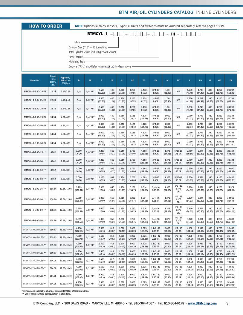
HOW TO ORDER
BTM Cylinder In-line (I) Series .................................................................................................................. 23BTM Cylinder Satellite (S) Series ............................................................................................................ 23
BTM Company, LLC. • 300 DAVIS ROAD • MARYSVILLE, MI 48040 • Tel: 810-364-4567 • Fax: 810-364-6178 • www.BTMcomp.com

8
BTM IN-LINE CYLINDERS
The in-line cylinder is a totally self-contained, cost-effective power source ideally suited for a wide variety of assembly and forming applications. Available in sizes from 1 to 100 tons, up to 8.00” stroke, and .50” power stroke, the In-Line Series cylinders provide the greatest force per dollar invested.
Modifications such as rod end styles, port locations, approach and power stroke lengths are options available upon request. Please contact BTM for more information.
BTM AIR/OIL CYLINDERS CATALOG IN-LINE CYLINDERS
STANDARD FEATURES
• Total air/oil separation• Linear force output• Three moving components• Simple control circuits• 100,000 PSI tensile tie rods• NFPA medium duty mounting styles• Operation in any position or attitude• 4.7 million MTBF (mean time between failure), . 20 million service life
• Field serviceable-seal kits• Fill units/repair manual• Heavy-duty construction designed for years of trouble free use• Numerous options, such as gage kits, sensors, press frames and bases.• 3 year warranty
MOUNTING STYLE FH MOUNTING STYLE UH
BTM Company, LLC. • 300 DAVIS ROAD • MARYSVILLE, MI 48040 • Tel: 810-364-4567 • Fax: 810-364-6178 • www.BTMcomp.com
9
BTM AIR/OIL CYLINDERS CATALOG IN-LINE CYLINDERS
*Dimensions subject to change. Contact BTM for official drawings.** UH of FH mounting configuration is standard.
Model No.
Output Force
per PSI (lbs.)
Approach/Retract per
PSI (lbs.)D EE F FB G UF TF KK M MT R RD RF WF ZB
BTMCYL-I-1-2.00-.25-FH 22.34 3.14/2.35 N/A 1/8” NPT 2.500 (63.50)
.440(11.18)
1.250 (31.75)
4.250(107.95)
3.438(87.33)
3/4-161.0DP.
1.00(25.40) N/A 1.630
(41.40)1.749
(44.42).380
(9.65)1.250
(31.75)20.207
(513.26)
BTMCYL-I-1-4.00-.25-FH 22.34 3.14/2.35 N/A 1/8” NPT 2.500(63.50)
.440(11.18)
1.250 (31.75)
4.250(107.95)
3.438(87.33)
3/4-161.0DP.
1.00(25.40) N/A 1.630
(41.40)1.749
(44.42).380
(9.65)1.250
(31.75)27.280
(692.91)
BTMCYL-I-1-6.00-.25-FH 22.34 3.14/2.35 N/A 1/8” NPT 2.500(63.50)
.440(11.18)
1.250 (31.75)
4.250(107.95)
3.438(87.33)
3/4-161.0DP.
1.00(25.40) N/A 1.630
(41.40)1.749
(44.42).380
(9.65)1.250
(31.75)34.260
(870.20)
BTMCYL-I-2-2.00-.25-FH 54.54 4.90/4.11 N/A 1/4” NPT 3.000(76.20)
.440(11.18)
1.250(31.75)
5.125(130.18)
4.125(104.78)
3/4-161.0DP.
1.000(25.40) N/A 2.050
(52.07)1.749
(44.42).380
(9.65)1.250
(31.75)21.289
(540.74)
BTMCYL-I-2-4.00-.50-FH 54.54 4.90/4.11 N/A 1/4” NPT 3.000(76.20)
.440(11.18)
1.250(31.75)
5.125(130.18)
4.125(104.78)
3/4-161.0DP.
1.000(25.40) N/A 2.050
(52.07)1.749
(44.42).380
(9.65)1.250
(31.75)30.925
(785.50)
BTMCYL-I-2-6.00-.50-FH 54.54 4.90/4.11 N/A 1/4” NPT 3.000(76.20)
.440(11.18)
1.250(31.75)
5.125(130.18)
4.125(104.78)
3/4-161.0DP.
1.000(25.40) N/A 2.050
(52.07)1.749
(44.42).380
(9.65)1.250
(31.75)37.780
(959.61)
BTMCYL-I-2-8.00-.50-FH 54.54 4.90/4.11 N/A 1/4” NPT 3.000(76.20)
.440(11.18)
1.250(31.75)
5.125(130.18)
4.125(104.78)
3/4-161.0DP.
1.000(25.40) N/A 2.050
(52.07)1.749
(44.42).380
(9.65)1.250
(31.75)44.638
(1133.81)
BTMCYL-I-4-2.00-.25-** 87.62 8.29/6.81 3.000(76.20) 3/8” NPT 4.250
(107.95).562
(14.27)1.250
(31.75)5.750
(146.05)4.688
(119.08)3/4-161.0DP.
1.375(34.93)
5/16-18.75 DP.
2.750(69.85)
2.374(60.30)
.380(9.65)
1.250(31.75)
23.169(588.49)
BTMCYL-I-4-4.00-.50-** 87.62 8.29/6.81 3.000(76.20) 3/8” NPT 4.250
(107.95).562
(14.27)1.250
(31.75)5.750
(146.05)4.688
(119.08)3/4-161.0DP.
1.375(34.93)
5/16-18.75 DP.
2.750(69.85)
2.374(60.30)
.380(9.65)
1.250(31.75)
32.183(817.45)
BTMCYL-I-4-6.00-.50-** 87.62 8.29/6.81 3.000(76.20) 3/8” NPT 4.250
(107.95).562
(14.27)1.250
(31.75)5.750
(146.05)4.688
(119.08)3/4-161.0DP.
1.375(34.93)
5/16-18.75 DP.
2.750(69.85)
2.374(60.30)
.380(9.65)
1.250(31.75)
38.930(988.82)
BTMCYL-I-4-8.00-.50-** 87.62 8.29/6.81 3.000(76.20) 3/8” NPT 4.250
(107.95).562
(14.27)1.250
(31.75)5.750
(146.05)4.688
(119.08)3/4-161.0DP.
1.375(34.93)
5/16-18.75 DP.
2.750(69.85)
2.374(60.30)
.380(9.65)
1.250(31.75)
46.426(1179.22)
BTMCYL-I-8-2.00-.25-** 158.86 12.56/11.08 3.999(101.57) 3/8” NPT 5.000
(127.00).656
(16.66)1.250
(31.75)6.250
(158.75)5.314
(134.98)3/4 - 161.25 DP.
1.375(34.93)
1/2 - 131.375
DP.
3.320(84.33)
2.374(60.30)
.380(9.65)
1.250(31.75)
24.973(634.31)
BTMCYL-I-8-4.00-.50-** 158.86 12.56/11.08 3.999(101.57) 3/8” NPT 5.000
(127.00).656
(16.66)1.250
(31.75)6.250
(158.75)5.314
(134.98)3/4 - 161.25 DP.
1.375(34.93)
1/2 - 131.375
DP.
3.320(84.33)
2.374(60.30)
.380(9.65)
1.250(31.75)
34.956(887.88)
BTMCYL-I-8-6.00-.50-** 158.86 12.56/11.08 3.999(101.57) 3/8” NPT 5.000
(127.00).656
(16.66)1.250
(31.75)6.250
(158.75)5.314
(134.98)3/4 - 161.25 DP.
1.375(34.93)
1/2 - 131.375
DP.
3.320(84.33)
2.374(60.30)
.380(9.65)
1.250(31.75)
41.779(1061.19)
BTMCYL-I-8-8.00-.50-** 158.86 12.56/11.08 3.999(101.57) 3/8” NPT 5.000
(127.00).656
(16.66)1.250
(31.75)6.250
(158.75)5.314
(134.98)3/4 - 161.25 DP.
1.375(34.93)
1/2 - 131.375
DP.
3.320(84.33)
2.374(60.30)
.380(9.65)
1.250(31.75)
48.603(1234.52)
BTMCYL-I-10-2.00-.25-** 259.63 19.63/16.49 4.250 (107.95) 1/2” NPT 6.500
(165.10).812
(20.62)1.500
(38.10)8.000
(203.20)6.625
(168.28)1 1/2 - 12 2.25 DP.
2.000 (50.80)
1/2 - 13 .75 DP.
4.100 (104.14)
2.999 (76.17)
.380 (9.65)
1.750 (44.45)
26.430 (671.32)
BTMCYL-I-10-4.00-.50-** 259.63 19.63/16.49 4.250 (107.95) 1/2” NPT 6.500
(165.10).812
(20.62)1.500
(38.10)8.000
(203.20)6.625
(168.28)1 1/2 - 12 2.25 DP.
2.000 (50.80)
1/2 - 13 .75 DP.
4.100 (104.14)
2.999 (76.17)
.380 (9.65)
1.750 (44.45)
36.437 (925.50)
BTMCYL-I-10-6.00-.50-** 259.63 19.63/16.49 4.250 (107.95) 1/2” NPT 6.500
(165.10).812
(20.62)1.500
(38.10)8.000
(203.20)6.625
(168.28)1 1/2 - 12 2.25 DP.
2.000 (50.80)
1/2 - 13 .75 DP.
4.100 (104.14)
2.999 (76.17)
.380 (9.65)
1.750 (44.45)
42.500 (1079.50)
BTMCYL-I-10-8.00-.50-** 259.63 19.63/16.49 4.250 (107.95) 1/2” NPT 6.500
(165.10).812
(20.62)1.500
(38.10)8.000
(203.20)6.625
(168.28)1 1/2 - 12 2.25 DP.
2.000 (50.80)
1/2 - 13 .75 DP.
4.100 (104.14)
2.999 (76.17)
.380 (9.65)
1.750 (44.45)
49.313(1252.55)
BTMCYL-I-15-2.00-.25-** 314.08 19.63/16.49 4.250 (107.95) 1/2” NPT 6.500
(165.10).812
(20.62)1.500
(38.10)8.000
(203.20)6.625
(168.28)1 1/2 - 12 2.25 DP.
2.000 (50.80)
1/2 - 13 .75 DP.
4.100 (104.14)
3.000 (76.20)
.380 (9.65)
1.750 (44.45)
28.740(730.00)
BTMCYL-I-15-4.00-.50-** 314.08 19.63/16.49 4.250 (107.95) 1/2” NPT 6.500
(165.10).812
(20.62)1.500
(38.10)8.000
(203.20)6.625
(168.28)1 1/2 - 12 2.25 DP.
2.000 (50.80)
1/2 - 13 .75 DP.
4.100 (104.14)
3.000 (76.20)
.380 (9.65)
1.750 (44.45)
40.505(1028.83)
BTMCYL-I-15-6.00-.50-** 314.08 19.63/16.49 4.250 (107.95) 1/2” NPT 6.500
(165.10).812
(20.62)1.500
(38.10)8.000
(203.20)6.625
(168.28)1 1/2 - 12 2.25 DP.
2.000 (50.80)
1/2 - 13 .75 DP.
4.100 (104.14)
3.000 (76.20)
.380 (9.65)
1.750 (44.45)
43.530(1105.66)
BTMCYL-I-15-8.00-.50-** 314.08 19.63/16.49 4.250 (107.95) 1/2” NPT 6.500
(165.10).812
(20.62)1.500
(38.10)8.000
(203.20)6.625
(168.28)1 1/2 - 12 2.25 DP.
2.000 (50.80)
1/2 - 13 .75 DP.
4.100 (104.14)
3.000 (76.20)
.380 (9.65)
1.750 (44.45)
51.488(1307.80)
®
24
®
www.hypercyl.comO
rder
ing
Info
rmat
ion
Ordering Information
19-21
19-21
19-21
19-21
HZ
Options such as sensors, HyperFill Units and switches must be ordered seperately. refer to pages 19-20.
BTMCYL - I
BTMCYL - S
NOTE: Options such as sensors, HyperFill Units and switches must be ordered seperately. refer to pages 18-19.HOW TO ORDER
18-20
BTM Company, LLC. • 300 DAVIS ROAD • MARYSVILLE, MI 48040 • Tel: 810-364-4567 • Fax: 810-364-6178 • www.BTMcomp.com

10
*Dimensions subject to change. Contact BTM for official drawings.** UH of FH mounting configuration is standard.
Model No.
Output Force
per PSI (lbs.)
Approach/Retract per
PSI (lbs.)D EE F FB G UF TF KK M MT R RD RF WF ZB
BTMCYL-I-20-2.00-.25-** 387.85 19.63/16.49 4.250 (107.95)
1/2” NPT
6.500 (165.10)
.812(20.62)
1.500 (38.10)
8.000(203.20)
6.625(168.28)
1 1/2-122.25 DP.
2.00(50.80)
1/2-13.75 DP.
4.100(104.14)
3.000(76.20)
.380(9.65)
1.750(44.45)
30.376(771.55)
BTMCYL-I-20-4.00-.50-** 387.85 19.63/16.49 4.250 (107.95)
1/2” NPT
6.500 (165.10)
.812(20.62)
1.500 (38.10)
8.000(203.20)
6.625(168.28)
1 1/2-122.25 DP.
2.00(50.80)
1/2-13.75 DP.
4.100(104.14)
3.000(76.20)
.380(9.65)
1.750(44.45)
44.000(1117.60)
BTMCYL-I-20-6.00-.50-** 387.85 19.63/16.49 4.250 (107.95)
1/2” NPT
6.500 (165.10)
.812(20.62)
1.500 (38.10)
8.000(203.20)
6.625(168.28)
1 1/2-122.25 DP.
2.00(50.80)
1/2-13.75 DP.
4.100(104.14)
3.000(76.20)
.380(9.65)
1.750(44.45)
47.910(1216.91)
BTMCYL-I-20-8.00-.50-** 387.85 19.63/16.49 4.250 (107.95)
1/2” NPT
6.500 (165.10)
.812(20.62)
1.500 (38.10)
8.000(203.20)
6.625(168.28)
1 1/2-122.25 DP.
2.00(50.80)
1/2-13.75 DP.
4.100(104.14)
3.000(76.20)
.380(9.65)
1.750(44.45)
53.167(1350.44)
BTMCYL-I-30-2.00-.25-** 651.44 28.27/23.37 6.280 (159.51)
3/4” NPT
7.500 (190.50)
1.060(26.92)
2.000(50.80)
11.250(285.75)
9.440(239.78)
1 7/8-123.0 DP.
2.500(63.50)
3/4-101.25 DP.
5.730(145.54)
3.749(95.22)
.500(12.70)
1.750(44.45)
34.939(887.45)
BTMCYL-I-30-4.00-.50-** 651.44 28.27/23.37 6.280 (159.51)
3/4” NPT
7.500 (190.50)
1.060(26.92)
2.000(50.80)
11.250(285.75)
9.440(239.78)
1 7/8-123.0 DP.
2.500(63.50)
3/4-101.25 DP.
5.730(145.54)
3.749(95.22)
.500(12.70)
1.750(44.45)
49.125(1247.78)
BTMCYL-I-30-6.00-.50-** 651.44 28.27/23.37 6.280 (159.51)
3/4” NPT
7.500 (190.50)
1.060(26.92)
2.000(50.80)
11.250(285.75)
9.440(239.78)
1 7/8-123.0 DP.
2.500(63.50)
3/4-101.25 DP.
5.730(145.54)
3.749(95.22)
.500(12.70)
1.750(44.45)
53.090(1348.49)
BTMCYL-I-30-8.00-.50-** 651.44 28.27/23.37 6.280 (159.51)
3/4” NPT
7.500 (190.50)
1.060(26.92)
2.000(50.80)
11.250(285.75)
9.440(239.78)
1 7/8-123.0 DP.
2.500(63.50)
3/4-101.25 DP.
5.730(145.54)
3.749(95.22)
.500(12.70)
1.750(44.45)
56.811(1443.00)
BTMCYL-I-50-2.00-.25-FH 1050.44 50.26/43.20 N/A 3/4” NPT
11.000(279.40)
1.312(33.32)
2.000(50.80)
15.500(393.70)
13.250(336.55)
2 1/4-123.5 DP.
3.000 (76.20) N/A 8.500
(215.90)4.300
(109.22).500
(12.70)2.000
(50.80)35.710
(907.03)
BTMCYL-I-50-4.00-.50-FH 1050.44 50.26/43.20 N/A 3/4” NPT
11.000(279.40)
1.312(33.32)
2.000(50.80)
15.500(393.70)
13.250(336.55)
2 1/4-123.5 DP.
3.000 (76.20) N/A 8.500
(215.90)4.300
(109.22).500
(12.70)2.000
(50.80)48.548
(1233.12)
BTMCYL-I-50-6.00-.50-FH 1050.44 50.26/43.20 N/A 3/4” NPT
11.000(279.40)
1.312(33.32)
2.000(50.80)
15.500(393.70)
13.250(336.55)
2 1/4-123.5 DP.
3.000 (76.20) N/A 8.500
(215.90)4.300
(109.22).500
(12.70)2.000
(50.80)53.350
(1355.09)
BTMCYL-I-50-8.00-.50-FH 1050.44 50.26/43.20 N/A 3/4” NPT
11.000(279.40)
1.312(33.32)
2.000(50.80)
15.500(393.70)
13.250(336.55)
2 1/4-123.5 DP.
3.000 (76.20) N/A 8.500
(215.90)4.300
(109.22).500
(12.70)2.000
(50.80)57.100
(1450.34)
BTMCYL-I-75-2.00-.25-** 1551.40 78.54/65.97 N/A 3/4” NPT
14.000(355.60)
1.812(46.02)
3.000(76.20)
19.000(482.60)
15.875(403.23)
2-1/4-123.0 DP.
4.000(101.60) N/A 9.620
(244.35)5.251
(133.38).500
(12.70)1.750
(44.45)36.680
(931.67)
BTMCYL-I-75-4.00-.50-** 1551.40 78.54/65.97 N/A 3/4” NPT
14.000(355.60)
1.812(46.02)
3.000(76.20)
19.000(482.60)
15.875(403.23)
2-1/4-123.0 DP.
4.000(101.60) N/A 9.620
(244.35)5.251
(133.38).500
(12.70)1.750
(44.45)49.733
(1263.22)
BTMCYL-I-75-6.00-.50-** 1551.40 78.54/65.97 N/A 3/4” NPT
14.000(355.60)
1.812(46.02)
3.000(76.20)
19.000(482.60)
15.875(403.23)
2-1/4-123.0 DP.
4.000(101.60) N/A 9.620
(244.35)5.251
(133.38).500
(12.70)1.750
(44.45)53.472
(1358.19)
BTMCYL-I-75-8.00-.50-** 1551.40 78.54/65.97 N/A 3/4” NPT
14.000(355.60)
1.812(46.02)
3.000(76.20)
19.000(482.60)
15.875(403.23)
2-1/4-123.0 DP.
4.000(101.60) N/A 9.620
(244.35)5.251
(133.38).500
(12.70)1.750
(44.45)57.348
(1456.64)
BTMCYL-I-100-2.00-.25-** 1963.5 78.54/65.97 N/A 3/4” NPT
14.000(355.60)
1.812(46.02)
3.000(76.20)
19.000(482.60)
15.875(403.23)
2-1/4-123.0 DP.
4.000(101.60) N/A 9.620
(244.35)5.251
(133.38).500
(12.70)1.750
(44.45)39.298
(998.17)
BTMCYL-I-100-4.00-.50-** 1963.5 78.54/65.97 N/A 3/4” NPT
14.000(355.60)
1.812(46.02)
3.000(76.20)
19.000(482.60)
15.875(403.23)
2-1/4-123.0 DP.
4.000(101.60) N/A 9.620
(244.35)5.251
(133.38).500
(12.70)1.750
(44.45)55.445
(1408.30)
BTMCYL-I-100-6.00-.50-** 1963.5 78.54/65.97 N/A 3/4” NPT
14.000(355.60)
1.812(46.02)
3.000(76.20)
19.000(482.60)
15.875(403.23)
2-1/4-123.0 DP.
4.000(101.60) N/A 9.620
(244.35)5.251
(133.38).500
(12.70)1.750
(44.45)58.653
(1489.79)
BTMCYL-I-100-8.00-.50-** 1963.5 78.54/65.97 N/A 3/4” NPT
14.000(355.60)
1.812(46.02)
3.000(76.20)
19.000(482.60)
15.875(403.23)
2-1/4-123.0 DP.
4.000(101.60) N/A 9.620
(244.35)5.251
(133.38).500
(12.70)1.750
(44.45)62.361
(1583.97)
BTM AIR/OIL CYLINDERS CATALOG IN-LINE CYLINDERS
IN-LINE CYLINDERS CONTINUED...
®
24
®
www.hypercyl.com
Ord
erin
g In
form
atio
n
Ordering Information
19-21
19-21
19-21
19-21
HZ
Options such as sensors, HyperFill Units and switches must be ordered seperately. refer to pages 19-20.
BTMCYL - I
BTMCYL - S
NOTE: Options such as sensors, HyperFill Units and switches must be ordered seperately. refer to pages 18-19.
HOW
TO
OR
DER
18-20
BTM Company, LLC. • 300 DAVIS ROAD • MARYSVILLE, MI 48040 • Tel: 810-364-4567 • Fax: 810-364-6178 • www.BTMcomp.com

11
IN-LINE CYLINDERS ENGINEERING DATA
BTM AIR/OIL CYLINDERS CATALOG IN-LINE CYLINDERS
Air Pressure
(PSI)
BTMCYL-I-1 Ton series
Hyd PSI/Force lb.
BTMCYL-I-2 Ton series
Hyd PSI/Force lb.
BTMCYL-I-4 Ton series
Hyd PSI/Force lb.
BTMCYL-I-8 Ton series
Hyd PSI/Force lb.
BTMCYL-I-10 Ton series
Hyd PSI/Force lb.
BTMCYL-I-15 Ton series
Hyd PSI/Force lb.
BTMCYL-I-20 Ton series
Hyd PSI/Force lb.
BTMCYL-I-30 Ton series
Hyd PSI/Force lb.
BTMCYL-I-50 Ton series
Hyd PSI/Force lb.
BTMCYL-I-75 Ton series
Hyd PSI/Force lb.
BTMCYL-I-100 Ton series
Hyd PSI/Force lb.
30 210/670 330/16360 316/2626 379/4766 396/7785 480/9422 591/11601 651/19540 630/31663 592/46542 750/58905
40 280/893 440/2181 422/3501 506/6355 528/10380 644/12641 788/15468 921/26053 840/42218 790/62056 1000/78540
50 350/1117 550/2727 528/4377 632/7943 661/12975 805/15802 985/19335 1152/32567 1050/52773 987/77570 1250/98175
60 420/1340 660/3272 633/5252 758/9532 793/15570 966/18962 1182/23202 1382/39080 1260/63327 1185/93084 1500/117810
70 490/1563 770/3817 739/6127 885/11120 925/18165 1127/22123 1379/27069 1612/45593 1470/73882 1382/108598 1750/137445
80 560/1787 880/4363 844/7003 1011/12709 1057/20760 1288/25283 1576/30936 1843/52107 1680/84436 1580/124112 2000/157080
90 630/2010 990/4908 950/7878 1137/14298 1189/23355 1449/28443 1773/34803 2073/58620 1890/94991 1777/139626 2250/176715
100 700/2234 1100/5454 1056/8754 1264/15886 1322/25950 1600/31408 1970/38671 2304/65134 2100/105546 1975/155140 2500/196350
*Typical cylinder break-away pressure is 35 PSI.(1) Complete cylinder cycle @ 60 PSI.Multiply value by cycles per minute for total SCFM usage.
NOTE: The above specifications are theoretical forces. Frictional loads and lack of proper air supply may affect cylinder performance. Please multiply application force requirements by 1.25-1.50 to ensure adequate force is available.
BTMCYL-I-1 Ton series
BTMCYL-I-2 Ton series
BTMCYL-I-4 Ton series
BTMCYL-I-8 Ton series
BTMCYL-I-10 Ton series
BTMCYL-I-15 Ton series
BTMCYL-I-20 Ton series
BTMCYL-I-30 Ton series
BTMCYL-I-50 Ton series
BTMCYL-I-75 Ton series
BTMCYL-I-100 Ton series
Approach Force per PSI (lbs.) *3.14 *4.90 *8.29 *12.56 *19.63 *19.63 *19.63 *28.27 *50.26 *78.54 *78.54
Retract Force per PSI (lbs.) *2.35 *4.11 *6.81 *11.08 *16.49 *16.49 *16.49 *23.37 *43.20 *65.97 *65.97
Output Force Range (lbs.) 670-2234 1636-5454 2626-8754 4766-15,886 7785-25,950 9424-31,408 11,635-38,785 19,540-65,134 31,663-105,546 46,542-155,140 58,905-196,350
Working Ratio (Output per PSI (lbs.)) 22.34:1 54.54:1 87.62:1 158.86:1 259.62:1 314.08:1 387.85:1 651.44:1 1055.46:1 1551.40:1 1963.5:1
Service Ratio(Hydraulic PSI (lbs.)) 7:01 11:1 10.56:1 12.64:1 13.22:1 16:1 19.7:1 23.04:1 21:1 19.8:1 25:1
Air Consumption per Cycle .136 SCFM(1) .267 SCFM(1) .426 SCFM(1) 1.079 SCFM(1) 1.079 SCFM(1) 1.356 SCFM(1) 1.568 SCFM(1) 2.510 SCFM(1) 4.204 SCFM(1) 7.160 SCFM(1) 8.51 SCFM(1)
Operating Temperature 10°F-160°F 10°F-160°F 10°F-160°F 10°F-160°F 10°F-160°F 10°F-160°F 10°F-160°F 10°F-160°F 10°F-160°F 10°F-160°F 10°F-160°F
Maximum Operating Speed *** 1.5 Ft/sec 1.5 Ft/sec 1.5 Ft/sec 1.5 Ft/sec 1.5 Ft/sec 1.5 Ft/sec 1.5 Ft/sec 1.5 Ft/sec 1.5 Ft/sec 1.5 Ft/sec 1.5 Ft/sec
Recommended Air Filter 40 Micron 40 Micron 40 Micron 40 Micron 40 Micron 40 Micron 40 Micron 40 Micron 40 Micron 40 Micron 40 Micron
Maximum Operating Pressure 100 PSI 100 PSI 100 PSI 100 PSI 100 PSI 100 PSI 100 PSI 100 PSI 100 PSI 100 PSI 100 PSI
Minimum Operating Pressure 30 PSI 30 PSI 30 PSI 30 PSI 30 PSI 30 PSI 30 PSI 30 PSI 30 PSI 30 PSI 30 PSI
*Typical cylinder break-away pressure is 35 PSI.(1) Complete cylinder cycle @ 60 PSI.Multiply value by cycles per minute for total SCFM usage.*** Maximum speed of the seals (not maximum speed of cylinder).
NOTE: The above specifications are theoretical forces. Frictional loads and lack of proper air supply may affect cylinder performance. Please multiply application force requirements by 1.25-1.50 to ensure adequate force is available.
BTM Company, LLC. • 300 DAVIS ROAD • MARYSVILLE, MI 48040 • Tel: 810-364-4567 • Fax: 810-364-6178 • www.BTMcomp.com

12
BTM SATELLITE SERIES CYLINDERS
The satellite cylinder is a totally selfcontained, cost-effective power source ideally suited for a wide variety of assembly and forming applications. Available in sizes from 1 to 100 tons, up to 8.00” stroke, and 1.00” power stroke, the HPS Series cylinder design provides a very compact package where space is limited.
The Satellite Series of cylinders permit the working cylinder to be located up to 10 ft. from the booster/reservoir section. Both components may be mounted in any position or attitude. Multiple working cylinders can also be operated with a single booster/reservoir unit.
Modifications such as rod end styles, port locations, approach and power stroke lengths are options available upon request. Please contact BTM for more information.
BTM AIR/OIL CYLINDERS CATALOG SATELLITE SERIES
STANDARD FEATURES
• Total air/oil separation• Linear force output• Three moving components• Internal shock pads• Fill and high pressure gage couplings• Hose assembly and disconnect• Two mounting styles• Simple control circuits • 100,000 PSI tensile tie rods• NFPA medium duty mounting styles
• Operation in any position or attitude• 4.7 million MTBF, 20 million service life• Field serviceable-seal kits• Fill units/repair manual• Heavy-duty construction designed for years of trouble free use• Numerous options, such as gage kits, sensors, press frames and bases.• 3 year warranty
MOUNTING STYLE FH MOUNTING STYLE UH
BTM Company, LLC. • 300 DAVIS ROAD • MARYSVILLE, MI 48040 • Tel: 810-364-4567 • Fax: 810-364-6178 • www.BTMcomp.com