Robust Design Workshop Chapter Page 1. Workshop Introduction 1.1 Previous Robust Design Workshops 4...
21
1 Robust Design Workshop Technical University of Denmark Robust Design Day 8 th of November 2017 This work is licensed under a Creative Commons Attribution-NonCommercial-ShareAlike 4.0 licence. CC BY-NC-SA Robustness of the Toyota Gas Pedal
Transcript of Robust Design Workshop Chapter Page 1. Workshop Introduction 1.1 Previous Robust Design Workshops 4...

1
Robust Design Workshop Technical University of Denmark
Robust Design Day 8th of November 2017
This work is licensed under a Creative Commons
Attribution-NonCommercial-ShareAlike 4.0 licence.
CC BY-NC-SA
Robustness of the Toyota Gas Pedal

Dear participants,
We would like to welcome you to the Robust Design Workshop at this year’s Robust Design Day. The Workshop is the fourth one hosted by the DTU Robust Design research group since the first Robust Design Day in August 2014, and we hope that there are many to come in the future.
The workshop aims at raising actual and future questions in Robust Design research. It is designed to encourage knowledge sharing through working together on a common problem and learning from each others’ techniques and approaches to Robust Design.
We hope that you enjoy the workshop and look forward to interesting results/discussions that help us all to get a deeper insight into Robust Design and related topics.
The Organising team
2
Preface

3
Chapter Page
1. Workshop Introduction
1.1 Previous Robust Design Workshops 4
1.2 Case: Toyota Acceleration Pedal 5
1.3 Workshop Objectives 6
2. The Acceleration Pedal‘s functionality
2.1 Basic Function 8
2.2 Functional Requirements 10
3. The Acceleration Pedal in Detail
3.1 Specifications 13
3.2 Part Drawings 15
Content

Chosen Workshop Format Continuously running discussion platform for:
sharing recent advances, experiences, and challenges about Robust Design as well as related disciplines
to discuss and test out different RD methods, theory, and tools on real case studies in a hands-on workshop format
to network, to collaborate, and to discuss ideas
Previous Robust Design Workshops: ISoRD’14 – Forensic Engineering (case: GM Ignition Switch)
RD Day’15 – Robust Embodiment Design (case: Glue Gun)
RD Day’16 – Variation Management (case: Smartphone wind meter)
4
1. Workshop Introduction
Previous Workshops
For further information, please visit http://robustdesign.org/workshop/

Scenario of this year’s workshop: As your team has the task to design an acceleration pedal in an electronic throttle control, you are of course aware of the infamous recall that Toyota launched in 2011. As they were said to be (among other things) related to a faulty pedal design, you use Toyota’s solution as a starting point for your design efforts.
Findings of the recall After several accidents, reports from across Europe and the US had shown that these were related to the accelerator pedal sticking and not bouncing back into position properly. The recall was initiated when it became apparent that the pedal could become completely stuck and had to be pulled back up.
5
1. Workshop Introduction
The Case – Toyota Acceleration Pedal
Source: https://www.theatlantic.com/

Guiding questions behind this year’s Robust Design workshop:
This year’s workshop focusses on Toyota’s recall of more than 4 million vehicles in 2010. By means of three consecutive exercises, the workshop guides you through a consideration of the observed mechanical sticking of the accelerator pedal in order to raise the question:
What is the coverage of available Robust Design approaches, and what are the challenges for an early assessment of product robustness?
At the same time, the organisers would like to emphasise that the workshop is build around an initial (simplified) investigation of the pedal assembly conducted by the Robust Design research group at DTU.
For this reason, we look forward to all additional questions you might have, to your ideas for different solutions, and particularly to feedback what you would require from a practitioner’s perspective to avoid corresponding issues in your every day work.
6
1. Workshop Introduction
Workshop Objectives

7
Chapter Page
1. Workshop Introduction
1.1 Previous Robust Design Workshops 4
1.2 Case: Toyota Acceleration Pedal 5
1.3 Workshop Objectives 6
2. The Acceleration Pedal‘s functionality
2.1 Basic Function 8
2.2 Functional Requirements 10
3. The Acceleration Pedal in Detail
3.1 Specifications 13
3.2 Part Drawings 15
Content

Acceleration pedal’s components
8
2. The acceleration pedal in detail
The pedal‘s basic functionality
Housing
Pedal arm
Spring
Axle
Sleeve
Sensor
Component Material
Housing PA6.6 GF 40 (40% glass reinforced Nylon)
Pedal Arm PA6.6 GF 40 (40% glass reinforced Nylon)
Friction Arm PA6.6 GF 40 (40% glass reinforced Nylon)
Sleeves CDA 932 (bearing bronze)
Axle Stainless steel
Spiral Spring ASTM A313 (Stainless steel spring wire)
For material properties see material databases (e.g. www.matweb.com).
Friction arm
Sleeve

The acceleration pedal’s main purpose As part of an electronic throttle control, the pedal assembly converts the position of the pedal arm to an electronic signal controlling the throttle position. Without any mechanical linkages, electronic accelerator pedals at the same time significantly reduce the inherent friction of cable-driven throttle systems.
As customers however “generally prefer the tactile response of these conventional solutions”, the pedal’s main purpose is twofold:
FR1 Correct readings Accurately position pedal arm relative to the sensor.
FR2 Emulate tactile response Ensure commonly accepted tactile response of conventional cable-driven pedals by means of a friction device.
9
2. The acceleration pedal‘s functionality
Basic functions

Required force displacement curve
10
2. The acceleration pedal‘s functionality
Functional Requirements
𝑭
1. Initial force required to begin depressing pedal arm. 2. Smaller increase in pedal force necessary to continue
moving pedal arm after initial displacement. 3. Decrease in foot pedal force before pedal arm
begins movement (reduced foot pedal force). 4. Pedal assembly in motion towards idle position.
Forc
e 𝑭
displacement 𝒙
①
② ③
④
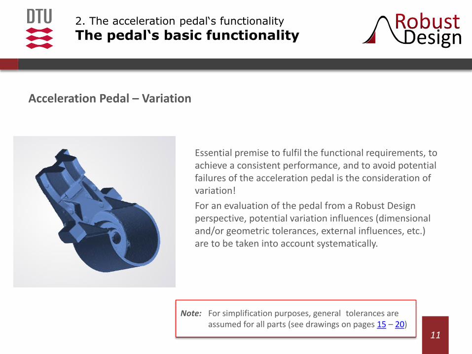
Acceleration Pedal – Variation
Essential premise to fulfil the functional requirements, to achieve a consistent performance, and to avoid potential failures of the acceleration pedal is the consideration of variation!
For an evaluation of the pedal from a Robust Design perspective, potential variation influences (dimensional and/or geometric tolerances, external influences, etc.) are to be taken into account systematically.
11
2. The acceleration pedal‘s functionality
The pedal‘s basic functionality
Note: For simplification purposes, general tolerances are assumed for all parts (see drawings on pages 15 – 20)

12
Chapter Page
1. Workshop Introduction
1.1 Previous Robust Design Workshops 4
1.2 Case: Toyota Acceleration Pedal 5
1.3 Workshop Objectives 6
2. The Acceleration Pedal‘s functionality
2.1 Basic Function 8
2.2 Functional Requirements 10
3. The Acceleration Pedal in Detail
3.1 Specifications 13
3.2 Part Drawings 15
Content

Other Specifications: • Rough tolerance guidelines
Unless otherwise specified in the part drawings (p. 15 – 20), general tolerances are assumed for simplification purposes.
– Tolerances on molded dimensions: ±0.05
– Angular tolerance on molded parts: ±1°
– Tolerances on machined dimensions: ±0.05
• Further parameters:
13
3. The acceleration pedal in detail
Specifications & Part Drawings
Variable explanation Value SI
kc Spring constant 10 N/mm
l Installation length spring 29 mm
μ Coefficient of friction (sleeves to axle)
≈ 0,1
μPA66
Coefficient of friction (PA6.6 self-mated contacts)
≈ 0,35

Friction performance of polymer materials This workshop relies on the (extremely) simplified assumption of linear friction between the different components of the assembly. The below given values for polymer contacts consequently need to be considered in the context of the workshop’s objective, i.e. to exemplify the benefits and limits of a systematic variation consideration.
14
3. The acceleration pedal in detail
Specifications & Part Drawings
source: adopted from https://www.dsm.com/
Note: For detailed investigations on the friction performance of PA66 composite reinforced by glass fibers, please refer to the literature.
Polystyrene (PS)
Polycarbonate (PC)
Polyethylene (PET)
Polyacetal (POM)
Nylon (PA6/PA66)
Fluoroplastics
Stamylan
0 0,1 0,2 0,3 0,4 0,5 0,6

15
3. The acceleration pedal in detail
Specifications & Part Drawings
Unless otherwise specified: Tolerances on dimensions: ±0.2 Angular tolerance: ±1°

16
3. The acceleration pedal in detail
Specifications & Part Drawings
Unless otherwise specified: Tolerances on dimensions: ±0.2 Angular tolerance: ±1°

17
3. The acceleration pedal in detail
Specifications & Part Drawings
Unless otherwise specified: Tolerances on dimensions: ±0.2 Angular tolerance: ±1°
18
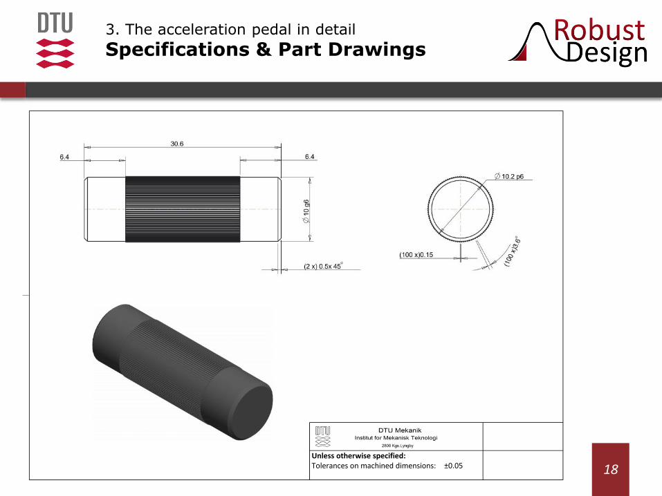
3. The acceleration pedal in detail
Specifications & Part Drawings
Unless otherwise specified: Tolerances on machined dimensions: ±0.05
19
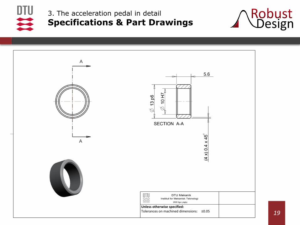
3. The acceleration pedal in detail
Specifications & Part Drawings
Unless otherwise specified: Tolerances on machined dimensions: ±0.05

20
3. The acceleration pedal in detail
Specifications & Part Drawings
Unless otherwise specified: Whole number dimensions: ±0.5 One decimal dimensions: ±0.1

Bjarklev, K.; Boorla, S.M.; Dabkowska, M.A.; and Eifler, T. (2017) “Use of Robustness Indicators” – Robust Design Day 2017 Workshop
This work is licensed under a Creative Commons Attribution-NonCommercial-ShareAlike4.0 licence. CC BY-NC-SA
This means you are welcome to use, alter and re-publish this material so long as it references to the original source (mentioned above). However, commercial use of the material is prohibited by this license.
For question regarding the material, exercise solutions, as well as university and industry workshops, please contact: [email protected]
21
Referencing and using this material