Robust, 17 Edition and Part L Compliant In-screed Heating ... · and Part L Compliant In-screed...
16
Underfloor Heating – made easy... Robust, 17 th Edition and Part L Compliant In-screed Heating Cable Fitting Guide – Version 2 Call 01444 247020 for Technical Support C O M P L I A N T C O M P L I A N T For Ice & Snow Systems see pages 11 – 14
Transcript of Robust, 17 Edition and Part L Compliant In-screed Heating ... · and Part L Compliant In-screed...

Underfloor Heating – made easy...
Robust, 17th Edition and Part L Compliant
In-screed Heating CableFitting Guide – Version 2
Call 01444 247020 for Technical Support
COMPLIANT
C
OMPLIAN
T
For Ice & SnowSystems see pages11 – 14

Please visit our website www.heatmat.co.uk for further information.2
Please ensure you read this guidecompletely before commencinginstallation of the underfloorheating. If you are unsure of anyaspect of the installation pleasecall Heat Mat’s Technical Supporthelpline on 01444 247020.
ContentsDo’s and don’ts 3Technical information 4Basic wiring diagram and warning label 5Cable spacing information 6Installation instructions 7Ice & Snow melting systems 11Warranty information 15Before commencing your installation, please check that you have the correctheater or combination of heaters for your chosen area. (see page 6 for details)
Heat Mat Limited accept no liability, either express or implied, for any consequential losses incurred as aresult of a Heat Mat system installation that does not conform to the following installation instructions.
Heat Mat 7mm Heating Cable is compatible with...
Thermostats Thermalinsulation boards
Levellingcompound
Ice & Snow Systems
Cable safeaccessory

For support please call 01444 247020 3
Do’s and Don’ts for internal heating systems• Do thoroughly read this guide beforecommencing installation
• Do space the cables evenly across thefloor to produce a uniform heat output
• Do ensure that all heating wire (including joints) is fitted beneath the floor covering
• Do use a multi-meter to test the cable,before, during and after covering (see page 4)
• Do connect multiple cables in parallel
• Do consider thermally insulating your sub-floor before installing theunderfloor heating system
• Do use a Heat Mat thermostat to control your system
• Do ensure that all electrical works conform to Part ‘P’ of the Building Regulations and current IEE Wiring Regulations
• Do ensure the system is protected by a suitable RCD device (30mA)
• Do ensure that all heating cable and connections are covered with a cementaceous screed of at least 50mm (min 65mm for Part L compliance) or 15mm of flexible self-levelling compound
• Do log on to www.heatmat.co.uk to ensure that you are using the most recent instructions
• Do ensure all heating cables are at least60mm away from each other
• Don’t cut, shorten, strain or cross the heating cables
• Don’t bend the joint between the element and cold tail
• Don’t supply power to the heater until thecable has been fully encased and the wettrade has been allowed to fully dry out
• Don’t lay cables closer than 60mm to conductive parts
• Don’t lay cables at an output greater than160W if covering with wood, vinyl or carpet
• Don’t install heating cables if the ambienttemperature is below 5ºC as they can become less flexible
• Don’t install the heating cable at an outputhigher than 270W/sqm unless approvalhas been received for this application from Heat Mat
• Don’t install the heating cables in walls or ceilings
• Don’t install the floor sensor close to otherheat sources such as hot water pipes
• Don’t begin covering with cementaceous screed or levelling compound until thesystem is in place and has been testedwith a multi-meter (see page 4)
• Don’t leave any sections of the heatingcable or connections in the open air orbeneath fixtures and fittings wheninstallation is completed
• Don’t use the heating system to help to dry out the wet trade

Please visit our website www.heatmat.co.uk for further information.4
7mm In-screed Heating Cable 20W/m technical specification
17th Edition Compliant Certified EMC safe
Manufactured in a BEAB approved factory CE Marked
Product code Length Wattage Resistance 270 W/m2 200 W/m2 160 W/m2
in metres c-c 7.5cm c-c 10.0cm c-c 12.5cm
PKC-7.0-0210 10.5 m 210 W 246 Ω 0.8 m2 1.1 m2 1.3 m2
PKC-7.0-0417 21.0 m 417 W 124 Ω 1.5 m2 2.1 m2 2.6 m2
PKC-7.0-0504 26.0 m 504 W 105 Ω 1.9 m2 2.5 m2 3.2 m2
PKC-7.0-0627 32.0 m 627 W 81 Ω 2.3 m2 3.1 m2 3.9 m2
PKC-7.0-0837 42.0 m 837 W 61 Ω 3.1 m2 4.2 m2 5.2 m2
PKC-7.0-1022 50.0 m 1022 W 53 Ω 3.8 m2 5.1 m2 6.4 m2
PKC-7.0-1246 62.0 m 1246 W 44 Ω 4.6 m2 6.2 m2 7.8 m2
PKC-7.0-1381 69.0 m 1381 W 40 Ω 5.1 m2 6.9 m2 8.6 m2
PKC-7.0-1774 89.0 m 1774 W 31 Ω 6.6 m2 8.9 m2 11.1 m2
PKC-7.0-2144 105.0 m 2144 W 26 Ω 7.9 m2 10.7 m2 13.4 m2
PKC-7.0-2458 123.0 m 2458 W 21 Ω 9.1 m2 12.3 m2 15.4 m2
PKC-7.0-3067 150.0 m 3067 W 17 Ω 11.4 m2 15.3 m2 19.2 m2
PRA-111-0001 12m Cable fixing band - sufficient for up to 75m of cable
PRA-111-0002 25m Cable fixing band - sufficient for up to 150m of cable
HCA-111-0008 25m Double-sided tape - for securing fixing bands
Test your heating cable with a multi-meter before unwrappingto confirm you have received it in working order.
The black cold tail is double insulated and carries an earth screen (silver braid), live and neutral wires.
Exposing the ends of these wires will allow the continuity tests to be carried out with a functional multi-meter.
This test should also be done before, during and aftercovering with screed or levelling compound.
At no point should any cable be connected to a power supply to test it.
Tests• Live to neutral = ohms value as listed above
• Live to earth and neutral to earth = both infinity
If your tests do not conform to the expected results please contact Heat Mat’s Technical Support Team.
Technical Data:General Construction: VDE approved dual conductor wire with earth
Voltage: 230 Vac – 50Hz
Maximum Load: 21 W/m
Maximum Cable Temperature: 90ºC
Approvals: CE marked
Wire Thickness: 6.8mm to 7.2mm depending on Ohm Value
Cable Flexibility: Minimum allowable cable radius is 50mm
Power Range: 210W-3067W
UV Resistance: Confirmed UV Resistant by VDE test institute
Approved in accordance with: EN 60335-1:1998, EN60335-2-17:1999, IEC 60730
IP Rating: IPX7 as required by the 17th Edition IEE Wiring Regulations
Construction:
Thermal Conductor: 2 x resistance 7 stranded wires insulated with 0.8mm silicon rubber (2G)
Additional Internal Insulation: Polyester sheath
Insulation Shield: Aluminium foil shield
Outer Insulation: PVC (105) UV resistant, tested to 90ºC
Reinforcement Materials: Fibreglass wire
Fixing Materials: Heat Fix metal bands can be used
For full fitting instructions please see ourwebsite www.heatmat.co.uk or contact us for advice.
Part L Compliant
COMPLIANT
C
OMPLIAN
T
PART L EMC Safe

For support please call 01444 247020 5
Basic wiring diagram and warning label
Power supplied
through an RCD
Fused Spur Thermostat
FUSE
1.3m above floor
Floor
Floor Sensor
18ºC11:05 Thu
Comfort Menu Manual
• All electrical works must be carried out by a certified electrician.
• A suitable RCD protection must be incorporated in this system.
• If the ampage of the thermostat is exceeded by your chosensystem, a contactor or similar device will be required. Allthermostats used must be of a two-pole design with a minimumopening between the contacts of 3mm.
• The heating cables must not be cut or cross each other or other wiring.
• The cold tail joint must be kept straight and located beneath thefinal floor covering and must be thoroughly encased in tileadhesive or levelling compound.
• Please consult your electrician to discuss your individual requirements.
Please see the back page of this fitting guide for the required information label for thedistribution board.
It is a legal requirement that this label iscompleted and the required information isdisplayed near the relevant distribution board.
Typical Wiring System
A. Robust PVC (Y) outer insulationB. 100% aluminium earth shield for safetyC. High load earth drain wireD. Fiberglass reinforcement cable for tensile strengthE. 0.8mm silicon rubber (2G)F. Resistance wires

Choosing the correct cable spacing (c-c)Calculate the total m2 of floor area you have inyour room, and then deduct any areas whereunderfloor heating should not be laid, such as anyfloor fixed furniture including baths, shower trays,kitchen units, central islands etc. This will giveyou your free floor area.
To calculate the wattage output per m2 you will have,divide the wattage listed for your cable/s by the m2
free floor area that you have to heat i.e.
2,144W11m2
Now you must calculate the cable to cable (c-c) distanceyou will lay your heating cable at. Divide the free floor areamultiplied by 100 by the total length of the cables youhave to lay i.e.
11m2 x 100105m
You should therefore, in this circumstance, lay all of the cables in runs roughly 10.5cm apart.
The 7mm Heating Cable table on page 4 can be used as a guide as it shows approximate m2 coverage of each cable when laying at 160W/m2 (c-c 12.5cm) and 200W/m2 (c-c 10cm). The table also shows 270W/m2
(c-c 7.5cm) which can be used in external ice and snowmelting systems.
As a guide to confirming the wattage per squaremetre (W/m2) that you require, please use thefollowing advice in conjunction with the tableshown at the top of page 4.
Standard rooms – 160W/m2 column: When using any suitable floor covering including tiles,carpet, vinyl or wood. These cables should be laid directlyonto subfloor insulation *insulated concrete bases. Theycan provide primary heating in well insulated areas andsecondary heating in other circumstances.
High heat loss rooms – 200W/m2 column:When using beneath tiles on subfloor insulation or*insulated concrete bases and when primary heating is apriority. If the system is being installed to provide the onlysource of heating, you would normally evenly space thecables in rows between 8.0 – 10.0cm apart to achievethis. Speak to your electrician or builder to confirm thatthe system output meets your individual requirements.
Although 100% coverage is achievable, a borderof roughly 50mm is recommended around theperimeter of the room as the heating cablesshould not touch the walls, kickboards etc.
We would recommend planning your installationbefore starting to lay your cable, and also thatyou photograph your cable layout before tiling for future reference.
The thermal resistance (insulation) between the top of theheated screed and the room must not have an insulationvalue higher than 0.125 m²K/W. Some typical insulationvalues for common floor coverings are listed below:
Wood fibre and rubber backed carpets are not suitable for use with underfloor heating.
The material used to cover the heating cable must have adensity of 1,500kg/m3 and a minimum heat transmissionof 1W/m K, all normal tile adhesives, levelling compoundsand screeds conform to this standard.
= an output of 195W/m2
= 10.5cm
Please visit our website www.heatmat.co.uk for further information.6
* Insulation within the floor base minimises downward heat loss allowing your underfloor heating to run more efficiently. Insulation laid directly beneath the underfloor heating will provide the largest benefit, and the further down in the floor build the insulation is (such as beneath a screed) the less benefit it will offer. Systems laid onto very badly insulated floor bases may not meet your expectations.
Tiled, stone and thin vinyl floors up to 0.035 m²K/W
Linoleum floors and thick vinyl floors up to 0.040 m²K/W
Hessian backed carpets with low Togunderlays up to
0.125 m²K/W
Parquet and laminate floors up to 18mmthick up to
0.125 m²K/W
Wood fibre floors and rubber backed carpets from
0.175 m²K/W

Installation instructions
Floor preparationThe sub-floor should be solid, level and reasonably dust free as would normally be required before pouringa screed. 7mm cables should always be laid onto aninsulation layer and this should be either foil faced (such as Cellotex Double-R) or concrete faced (such asHeat Mat thermal insulation board). If a damp-proofingmembrane is being installed this must be placedbeneath the heating cables. We would also recommendthat the entire floor base is of the same construction to ensure the system performs evenly.
It is acceptable to lay 7mm cables directly onto an existing well insulated concrete base or tiled floor,however in these circumstances we still recommendconsidering installing an additional layer of insulation, such as Heat Mat thermal insulation boards.
Underfloor heating cables must not be installed directlyonto a layer of soft insulation, it must have a layer ofconcrete or foil to facilitate an even heat spread.
If you have chosen to cover your system with Heat Matflexible levelling compound, Mira 4280 Primer should beused to prime the floor base. Levelling compounds canonly be installed onto structurally firm bases such asconcrete, tile or concrete faced insulation boards.
Installing the 7mm Heating Cable SystemTest each cable with a multi-meter before unpacking toensure you have received your product in full workingorder. (See bottom of page 4 for testing instructions.)
The heating cable can be secured in place via twomethods; either fixed to the floor using Heat Mat'smetallic fixing strips or alternatively zip tied in place to reinforcement mesh .
Normally the cable will be installed using metallic fixing strips and these are held to the floor by double-sided tape (fig.1), adhesive or they can be nail gunnedinto place (nail gunning is not suitable when used on top of a damp-proof membrane). The fixing strips should be placed on the floor in runs in the oppositeway to the direction you wish to lay the heating cable(fig.2). The runs of fixing strip should be spaced atroughly 1m intervals.
Using the information on page 6 of this booklet youshould calculate the average spacing that you need to achieve to evenly spread the cable out over your floor. If zip tying the cable to reinforcement mesh youshould simply space apart the runs of cable by thecalculated distance, however it is important that the zip ties should not be fastened too tight.
The fixing strip has pre-spaced cable fittings at 2.5cm intervals, and if your calculated spacing is at 10cm or 12.5cm intervals then simply fix the cablesin the appropriate slots. If, however, your required cable spacing does not closely match the availablespacings then you will need to compensate for this by laying alternate runs at different spacings.
If, for instance, your required cable spacing was11.25cm, then to achieve this overall spacing on yourfloor you should lay the first and second run of cable
For support please call 01444 247020 7
fig.2fig.1

10cm apart, and then the second and third run 12.5cm apart and then repeat this pattern across the floor. This would give an average spacing of thedesired 11.25cm.
The cable is locked into the fixing strips by bending the metal hook over the cable, pushing the hoop overthe cable and hook, and then pulling the hook backdown to secure the hoop and cable in place. Themethod of installation is shown above in fig. 4 and 5.
The cables should run from one side of the room to theother, being locked in place every time they pass overthe fixing strip, and then a second run of cable shouldreturn across the room parallel to the first run. Youshould then continue this process until the cable is used up, and then start laying a second cable in asimilar way if one is required.
Remember to maintain even spacing wherever possible to ensure a constant output across the floor area. Thecable runs must never be less than 60mm apart and if you find that your rows have to be 60mm or less to fityour room, STOP, as the cable is too big for your area. The heating cable can not be cut to shorten it’s lengthwithout being destroyed.
Ensure that the termination point at the end of the cable and the connection between the heating cable and the cold tail are kept straight and laid within thefloor area where they will be covered with either acementaceous screed or levelling compound. Thesemust not be covered with tape, but do have to be fully encased in screed or levelling compound.
Multiple cables can be installed in one room but mustbe connected in parallel (they do not join together). Up to 2 cables can be physically wired into the back of the thermostat. More than 2 cables will require aconnection box. If your system exceeds the Ampagerating of your chosen thermostat, your electrician can install a contactor or similar device to allow theheating system to operate safely through a singlethermostat for ease of control.
Test the heater/s with a multi-meter again prior to covering.
If covering is not going to happen straight away restrict any traffic above the cable to a minimum.
Covering the Heating Cable SystemWear soft soled shoes. Do not allow any unnecessarytraffic across the cabled area until the floor covering iscompleted. Do not stack or cut tiles across the cabled areaand take care to avoid dropping sharp objects or tiles ontothe cables as this can crush or cut into them.
Check the resistance and continuity of the cable with amulti-meter regularly during installation. If the resistancechanges, or the cable goes to open circuit, the cable hasbeen damaged. In this case, please contact Heat Mat’sTechnical Support line on 01444 247020. Even a smallnick in or scratch to the outer insulation can lead tosystem failure when powered up over a period of time.
If the system is being covered with a cementaceousscreed this should be carefully poured over the heating
fig.3 fig.4
Please visit our website www.heatmat.co.uk for further information.8
Installation instructions

cables to an even depth of at least 50mm, and at least65mm for Part L compliance. The screed must be allowedto dry before laying further floor coverings and the heatingcables must not be used to 'dry out' the screed, as thiscould lead to the screed cracking or the cable failing.
If Heat Mat's flexible levelling compound is being usedto cover the heating cables then a layer of at least 15mmmust be used. In normal circumstances this levellingcompound will dry within 24 hours, and as with screedthe heating cables must not be used to 'dry it out'.
The floor sensor should be positioned in the finishedscreed layer or levelling compound as close to the top of this layer as possible. The floor sensor should extendroughly 400mm into the room and if using a levellingcompound rather than a screed, it must be locatedequidistant between two heating cables. If using thesystem as a night storage heater then the floor sensorcan be laid at the same level as the heating cables, and again it must be placed equidistant between twoheating cables.
The sensor cable can be extended if required up to 50m using a twin sheathed high temperature PVC cableand the connection between the two wires must bewaterproof and fully insulated. Ideally, the floor sensorshould be placed into a length of suitable close endedconduit (12-14mm diameter) so that it can be easilyreplaced if required (fig.6).
The floor sensor should not be fitted in areas affected byother heat sources, such as hot water pipes and radiators,or in an area that will be covered at a later date with items
such as rugs or flat bottomed furniture, as this will prevent the system from operating correctly. If using one of Heat Mat’s infra-red wall mounted floor sensorsyou are not required to include an additional floor sensorwithin the floor construction.
Once the screed or levelling compound has fully driedthe final floor covering can be laid.
If laying a tiled floor flexible tile adhesive and groutmust be used to ensure compatibility with the underfloorheating. With floating laminate or engineered boardfloors it is essential that the flooring is no more than18mm thick to ensure a good movement of heatthrough the covering, and with these floors any layer of soft insulation laid beneath the flooring must becompatible with installation on top of an underfloorheating system. For carpeted floors rubber backedcarpets should not be used and the Tog rating of thecarpet must be no more than 2.0 Tog and of theunderlay 0.8 Tog.
fig.5 fig.6
For support please call 01444 247020 9
Installation instructions
To check thatyou have thelatest set ofinstructionsplease followthis link

Electrical connectionsWiring can now be completed but no power should beapplied to the system until the adhesive, grout and/orlevelling compound is completely dry.
All work must comply with current IEE wiring regulationsand installations must comply with Part ‘P’ of the BuildingRegulations. Consult your Local Authority Building Controldepartment regarding their requirements for certificationor check with an electrician qualified to issue Part ‘P’certification regarding your individual installation.
The heating cable has to be wired into a thermostat with floor temperature limitation. Please see the separateinstructions in your Heat Mat thermostat box.
Run the cold tail connection and floor sensor cable inseparate plastic conduit or trunking from your heated floor to the thermostat position.
Up to 2 heating cables can be wired straight into thethermostat. A connection box will be required if installing 3 or more heating cables. Ensure that multiple cables are wired in parallel, not in series.
The mains power supply must be protected by a suitableRCD (30mA and up to 4.8kW).
The thermostat should be connected to the power supplyvia a suitably rated fused spur or circuit breaker.
Should the total loading from a combination of heatingcables exceed the Ampage rating of your chosen thermostat,the system will require the installation of a suitable ratedcontactor which will allow the heating system to be runthrough a single thermostat for ease of control.
Heat Mat’s thermostats are IP21 rated, which means that they can be installed within some bathrooms if there is a suitable area.
If the thermostat is placed outside the room to be heated, or inside a cupboard, the thermostat will have to be reprogrammed (when first switched on) to onlymonitor the floor sensor that has been placed into theheated floor space.
Remember:
If you are unsure how toproceed at any stage of theinstallation process, pleasecontact Heat Mat TechnicalSupport on 01444 247020 for guidance.
Living with your Underfloor Heating SystemTo ensure that your system works to its full capacity for the lifetime of the flooring, please ensure that thermal blocking is avoided above the heating system.
Thermal blocking occurs when the heat produced by thesystem warms the floor surface but is then trapped andhas no way of escaping from the surface of the floor. This can cause the system to overheat in the thermallyblocked area and, in extreme cases, affect the integrity of the floor covering and heating system.
Heat Mat’s thermostats are IP21 rated, and the heatingmats are IPX7 rated, which means systems can beinstalled in bathrooms and other ‘wet areas’ and if asuitable zone is available the thermostat can also beplaced in the bathroom.
Thermal blocking is not usually a problem within floorswhere the system has been covered with levellingcompound or tile adhesive and tiles, as these coveringsare efficient transmitters of heat themselves and will spread the heat around any thermal block. Thermal blocking has a greater chance of occurring in situations with a carpeted, wooden or laminate floor finish that do not utilise a levelling compound as these coverings do not transmit heat as effectively.
Please visit our website www.heatmat.co.uk for further information.10
Installation instructions

For support please call 01444 247020 11
Heat Mat External Ice and Snow Melting Systems
Heat Mat offer a wide range of Scandinaviandesigned outdoor de-icing systems for roofs,gutters, driveways and walkways. In mostcircumstances these systems will be basedaround the 7mm cable system which hasspecifically been designed to be robust enoughfor external use and is fully UV protected.
The majority of external heating systems are controlledusing one of our range of proprietary ice and snow meltingthermostats and these have a range of temperaturesensors to monitor ambient or ground temperature. Inaddition to temperature sensors our higher end ice andsnow melting thermostats also include the option of amoisture detector which ensures that the system will onlyoperate when it is cold and there is moisture present.Moisture sensors would normally cut the running costs ofa system by around 80%, as it is often very cold, but ifthere is no moisture present there is no risk of ice or snow,so the system does not need to be powered up.
Particular care should be taken when deciding where toplace the temperature and moisture sensors and werecommend that you thoroughly read the instructions thatare supplied with the thermostats and, if you are unclearon any points, please contact Heat Mat.
Installing the heating cables for external use is much thesame as with general installation instructions for beneath ascreed, however the covering over the cable (in the case ofdriveway or walkway heating) is obviously different and thethree most common installation methods are notedoverleaf. For roof and gutter heating systems there are anumber of alternative ways to install the heating cablesand these are briefly described in the following pages.
For additional installationinformation for external systems
please speak to Heat Mat’sTechnical Team on 01444 247020.
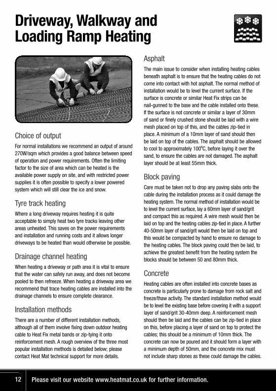
Choice of outputFor normal installations we recommend an output of around270W/sqm which provides a good balance between speedof operation and power requirements. Often the limitingfactor to the size of area which can be heated is theavailable power supply on site, and with restricted powersupplies it is often possible to specify a lower poweredsystem which will still clear the ice and snow.
Tyre track heatingWhere a long driveway requires heating it is quiteacceptable to simply heat two tyre tracks leaving otherareas unheated. This saves on the power requirementsand installation and running costs and it allows longerdriveways to be heated than would otherwise be possible.
Drainage channel heatingWhen heating a driveway or path area it is vital to ensurethat the water can safely run away, and does not becomepooled to then refreeze. When heating a driveway area werecommend that trace heating cables are installed into thedrainage channels to ensure complete clearance.
Installation methodsThere are a number of different installation methods,although all of them involve fixing down outdoor heatingcable to Heat Fix metal bands or zip-tying it ontoreinforcement mesh. A rough overview of the three mostpopular installation methods is detailed below; pleasecontact Heat Mat technical support for more details.
AsphaltThe main issue to consider when installing heating cablesbeneath asphalt is to ensure that the heating cables do notcome into contact with hot asphalt. The normal method ofinstallation would be to level the current surface. If thesurface is concrete or similar Heat Fix strips can be nail-gunned to the base and the cable installed onto these.If the surface is not concrete or similar a layer of 30mm of sand or finely crushed stone should be laid with a wiremesh placed on top of this, and the cables zip-tied inplace. A minimum of a 10mm layer of sand should then be laid on top of the cables. The asphalt should be allowedto cool to approximately 100ºC, before laying it over thesand, to ensure the cables are not damaged. The asphaltlayer should be at least 55mm thick.
Block pavingCare must be taken not to drop any paving slabs onto thecable during the installation process as it could damage theheating system. The normal method of installation would beto level the current surface, lay a 60mm layer of sand/gritand compact this as required. A wire mesh would then belaid on top and the heating cables zip-tied in place. A further40-50mm layer of sand/grit would then be laid on top andthis would be compacted by hand to ensure no damage tothe heating cables. The block paving could then be laid, toachieve the greatest benefit from the heating system theblocks should be between 50 and 80mm thick.
ConcreteHeating cables are often installed into concrete bases asconcrete is particularly prone to damage from rock salt andfreeze/thaw activity. The standard installation method wouldbe to level the existing base before covering it with a supportlayer of sand/grit 30-40mm deep. A reinforcement meshshould then be laid and the cables can be zip-tied in placeon this, before placing a layer of sand on top to protect thecables; this should be a minimum of 10mm thick. Theconcrete can now be poured and it should form a layer witha minimum depth of 50mm, and the concrete mix mustnot include sharp stones as these could damage the cables.
Please visit our website www.heatmat.co.uk for further information.12
Driveway, Walkway and Loading Ramp Heating
For support please call 01444 247020 13
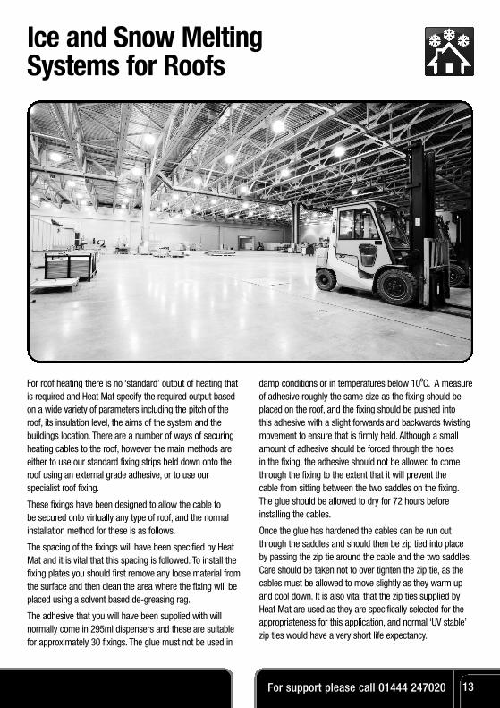
Ice and Snow Melting Systems for Roofs
For roof heating there is no ‘standard’ output of heating thatis required and Heat Mat specify the required output basedon a wide variety of parameters including the pitch of theroof, its insulation level, the aims of the system and thebuildings location. There are a number of ways of securingheating cables to the roof, however the main methods areeither to use our standard fixing strips held down onto theroof using an external grade adhesive, or to use ourspecialist roof fixing.
These fixings have been designed to allow the cable to be secured onto virtually any type of roof, and the normalinstallation method for these is as follows.
The spacing of the fixings will have been specified by HeatMat and it is vital that this spacing is followed. To install thefixing plates you should first remove any loose material fromthe surface and then clean the area where the fixing will beplaced using a solvent based de-greasing rag.
The adhesive that you will have been supplied with willnormally come in 295ml dispensers and these are suitablefor approximately 30 fixings. The glue must not be used in
damp conditions or in temperatures below 10ºC. A measureof adhesive roughly the same size as the fixing should beplaced on the roof, and the fixing should be pushed into this adhesive with a slight forwards and backwards twistingmovement to ensure that is firmly held. Although a smallamount of adhesive should be forced through the holes in the fixing, the adhesive should not be allowed to comethrough the fixing to the extent that it will prevent the cable from sitting between the two saddles on the fixing.The glue should be allowed to dry for 72 hours before installing the cables.
Once the glue has hardened the cables can be run outthrough the saddles and should then be zip tied into placeby passing the zip tie around the cable and the two saddles.Care should be taken not to over tighten the zip tie, as thecables must be allowed to move slightly as they warm upand cool down. It is also vital that the zip ties supplied byHeat Mat are used as they are specifically selected for theappropriateness for this application, and normal ‘UV stable’zip ties would have a very short life expectancy.

As with roof heating systems, each gutter heating systemis individually specified taking into account the localconditions. As a general rule, however, in a normal 125mm gutter we would recommend a double run of7mm cable (providing a total output of 40W per meter) to ensure that the gutter is kept clear of ice and snow.
It is important to heat the downpipes of any gutter heating system and in normal circumstances werecommend heating the first 1/3rd of the downpipe with two runs of the heating cable. In circumstanceswhere air temperatures are expected to fall below -10º C for a significant period of time we recommendheating the downpipe all the way down to ground level.
Heat Mat offer a variety of gutter heating cable fixingaccessories including spacers for the cable within thegutters, and suspension beams, chains and cable guidesto allow cables to be safely run in downpipes.
Gutter cable guides should be used to space the two runs of cable apart in the gutter to ensure that they do not touch, and these guides can be easily clipped over the side of the gutter and held in place with silicon sealant if required. The guides should be spaced roughlyevery 1m, and if possible we recommend installing the heating cables along the side of the gutter restingagainst the property.
Where the heating cable is going to pass down adownpipe it is essential to use a suspension beam toensure that the cable does not have to support its ownweight. The suspension beam is placed above thedownpipe in the gutter and the gutter protector is used to protect the gutter from excess heating as the cablepasses into and then back out of the gutter. The plasticdownpipe chain is fixed to the suspension beam, and the cable is held onto this chain using downpipe guides spaced at roughly 25cm intervals.
Please visit our website www.heatmat.co.uk for further information.14
Ice and Snow Melting Systems for Gutters
FRO-GUT-PROT Cable protector for gutters anddownpipes
FRO-GUT-GUIDCable guides for heating cable in standard gutters
FRO-GUT-CHAI 1m Chain for downpipe heating cable
FRO-GUT-DOWNCable guide for downpipe heating cable
FRO-GUT-BEAM Suspension beam fordownpipe chain

For support please call 01444 247020 15
Heat Mat Extended Warranty
Congratulations on your purchase of a Heat Mat electric underfloor heating system.The ultra-thin heating cable has been manufactured andsupplied in the European Union by Heat-Com a/s/Heat MatLimited, and the following Warranty is supplied inaccordance with the general product liability rules, as statedin Directive 85/374/CEE, and all relevant national laws. Youare provided with a ten year warranty on the heating cablefor eventual defects in material. Details and evidence ofdefects has to be presented to Heat-Com, Heat Mat or anauthorised UK or Ireland distributor for approval.
When your warranty is invoked, your damaged product will either be repaired or replaced free of charge to yourself.
Your warranty does not cover the following:
• Any faults caused by misuse.
• A system which has not been installed in accordance with the manufacturer’s guidelines.
• Any other subsequential or consequential damages. To provide clarification, these damages could include the cost of repairs to walls, floors, tiles; professional fees; utility expenses. We would however pay for anyreasonable damages which are a foreseeableconsequence of Heat Mat's negligence.
• Any system that had not been paid for in full.
Heat-Com a/s/Heat Mat Limited are covered by aninternational insurance covering warranty payments.
In addition to the above warranty, Heat Mat offer a 5 yearextension to the above warranty on your heating cable.To be covered by this extra warranty in addition to theabove stipulations you must also:
• Register your product atwww.heatmat.co.uk/warrantyregistrationwithin 90 days of purchase.
• Be able to provide your proof of purchase of the system, a normal retail invoice/receipt is sufficient for this purpose.
• Ensure the system has been installed in accordance with Heat Mat’s installation guidelines and it must beprotected by a suitable RCD.
• Ensure that all installation work is compliant with currentIEE wiring regulations and installations must comply withPart ‘P’ of the Building Regulations. You should retainyour Part ‘P’ certificate as proof of this.
If the above stipulations have been followed, Heat Mat will provide a five year warranty once the original ten year warranty expires for the heating cable. This warrantyruns for the life of the floor covering above the originalinstallation. This warranty covers manufacturing defects in the heating cable supplied. Details and evidence ofdefects has to be presented to Heat Mat or an authorisedUK or Ireland distributor for approval. When your warranty is invoked, your damaged product will either be repaired or replaced free of charge to yourself.
The repair or replacement of your system is the only remedyavailable to you under these warranties. None of the abovewarranties affect yo ur statutory rights. Heat-Com a/s andHeat Mat Limited will in no event be liable for consequentiallosses or secondary charges including, but not restricted to,the cost of replacing or repairing floor coverings, any costsassociated with utility expenses or running costs,professional fees relating to trades peoples’ subsequent work or any other damage caused to material items.
Heat Mat Limited, Ashwyn Business Centre,
Marchants Way, Burgess Hill. RH15 8QY
T 01444 247020 F 01444 247121
www.heatmat.co.uk

Please complete and display at your distribution board.
Details of Installation:
Electricians Name: Signature:
Company Name:& Address:Date:
Room with heating Installed:Total Wattage of system:
Please list the product code and test results of each elementafter installation (compare to install guide for rated resistance)
Product Code Resistance Rating Insulation Test Passed
In the event of flooding or when carrying out any repairs or alterationsdisconnect the Under Floor Heating and contact your electrician or
Heat Mat for advice
This warranty card should be left with the thermostat user manual, Heat Mat system installation guide and the installer's heater layout & wiring diagrams to meet IEE Wiring
regulations (17th Edition - section 753). These items should be permanently fixed near the relevant distribution board.
Warning
Do NOT pierce the floors above the system with nails, screws or other fasteners.
Do NOT expose the floor to thermal blocking or attempt to reduce the size of
This building is fitted with Heat Mat 100% earth shielded electric underfloor heating utilising a 230Vac supply.
Heat Mat Ltd - Tel No: 01444 247020see www.heatmat.co.uk for more under floor heating solutions
the heated floor area. (check suitability of floor covering with manufacturer & that furniture has 10mm (min) air void beneath it.)
(see installer diagram for heater positioning)
Heat Mat Limited, Ashwyn Business Centre, Marchants Way, Burgess Hill. RH15 8QY
www.heatmat.co.uk
Reproduction of part or all of the contents of this fitting guide in any form is prohibitedother than with the express writtenpermission of Heat Mat Limited.