Robot Controller RC700-A Option Teach Pendant TP3 · Robot Controller RC700-A Option Teach ......
86
Rev.2 EM158P3041F Robot Controller RC700-A Option Teach Pendant TP3
Transcript of Robot Controller RC700-A Option Teach Pendant TP3 · Robot Controller RC700-A Option Teach ......

Rev.2 EM158P3041F
Robot Controller RC700-A Option Teach Pendant
TP3

ii
Robot C
ontroller RC
700-A Option Teach P
endant TP3 Rev.2

RC700-A option TP3 Rev.2 i
Robot Controller RC700-A Option Teach Pendant
TP3
Rev.2
Copyright © 2015 SEIKO EPSON CORPORATION. All rights reserved.

ii RC700-A option TP3 Rev.2
FOREWORD Thank you for purchasing our robot products. This manual contains the information necessary for the correct use of the Teach Pendant. Please carefully read this manual and other related manuals before installing the robot system. Keep this manual handy for easy access at all times.
WARRANTY The robot system and its optional parts are shipped to our customers only after being subjected to the strictest quality controls, tests, and inspections to certify its compliance with our high performance standards. Product malfunctions resulting from normal handling or operation will be repaired free of charge during the normal warranty period. (Please ask your Regional Sales Office for warranty period information.) However, customers will be charged for repairs in the following cases (even if they occur during the warranty period): 1. Damage or malfunction caused by improper use which is not described in the manual,
or careless use. 2. Malfunctions caused by customers’ unauthorized disassembly. 3. Damage due to improper adjustments or unauthorized repair attempts. 4. Damage caused by natural disasters such as earthquake, flood, etc.
Warnings, Cautions, Usage:
1. If the robot system associated equipment is used outside of the usage conditions and
product specifications described in the manuals, this warranty is void. 2. If you do not follow the WARNINGS and CAUTIONS in this manual, we cannot be
responsible for any malfunction or accident, even if the result is injury or death. 3. We cannot foresee all possible dangers and consequences. Therefore, this manual
cannot warn the user of all possible hazards.

RC700-A option TP3 Rev.2 iii
TRADEMARKS Microsoft, Windows, and Windows logo are either registered trademarks or trademarks of Microsoft Corporation in the United States and/or other countries. Other brand and product names are trademarks or registered trademarks of the respective holders.
TRADEMARK NOTATION IN THIS MANUAL Microsoft® Windows® XP Operating system Microsoft® Windows® Vista Operating system Microsoft® Windows® 7 Operating system Microsoft® Windows® 8 Operating system Throughout this manual, Windows XP, Windows Vista, Windows 7, and Windows 8 refer to above respective operating systems. In some cases, Windows refers generically to Windows XP, Windows Vista, Windows 7, and Windows 8.
NOTICE
No part of this manual may be copied or reproduced without authorization. The contents of this manual are subject to change without notice. Please notify us if you should find any errors in this manual or if you have any comments regarding its contents.
INQUIRIES Contact the following service center for robot repairs, inspections or adjustments. If service center information is not indicated below, please contact the supplier office for your region.
Please prepare the following items before you contact us.
- Your controller model and its serial number
- Your manipulator model and its serial number
- Software and its version in your robot system
- A description of the problem
SERVICE CENTER
iv RC700-A option TP3 Rev.2
MANUFACTURER Seiko Epson Corporation Toyoshina Plant
Robotics Solutions Operations Division 6925 Toyoshina Tazawa, Azumino-shi, Nagano, 399-8285 Japan
TEL : +81-(0)263-72-1530 FAX : +81-(0)263-72-1495 SUPPLIERS North & South America Epson America, Inc. Factory Automation/Robotics
18300 Central Avenue Carson, CA 90746 USA
TEL : +1-562-290-5900 FAX : +1-562-290-5999 E-MAIL : [email protected] Europe Epson Deutschland GmbH Factory Automation Division
Otto-Hahn-Str.4 D-40670 Meerbusch Germany
TEL : +49-(0)-2159-538-1391 FAX : +49-(0)-2159-538-3170 E-MAIL : [email protected] China Epson (China) Co., Ltd. Factory Automation Division
7F, Jinbao Building No. 89, Jinbao Street, Dongcheng District, Beijing, China, 100005
TEL : +86-(0)-10-8522-1199 FAX : +86-(0)-10-8522-1120 Taiwan Epson Taiwan Technology & Trading Ltd. Factory Automation Division
14F, No.7, Song Ren Road, Taipei 110, Taiwan, ROC
TEL : +886-(0)-2-8786-6688 FAX : +886-(0)-2-8786-6677

RC700-A option TP3 Rev.2 v
Korea Epson Korea Co., Ltd. Marketing Team (Robot Business)
27F DaeSung D-Polis A, 606 Seobusaet-gil, Geumcheon-gu, Seoul, 153-803 Korea
TEL : +82-(0)-2-3420-6692 FAX : +82-(0)-2-558-4271 Southeast Asia Epson Singapore Pte. Ltd. Factory Automation System
1 HarbourFront Place, #03-02, HarbourFront Tower One, Singapore 098633
TEL : +65-(0)-6586-5696 FAX : +65-(0)-6271-3182 India Epson India Pvt. Ltd. Sales & Marketing (Factory Automation)
12th Floor, The Millenia, Tower A, No. 1, Murphy Road, Ulsoor, Bangalore, India 560008
TEL : +91-80-3051-5000 FAX : +91-80-3051-5005 Japan Epson Sales Japan Corporation
Factory Automation Systems Department Nishi-Shinjuku Mitsui Bldg. 6-24-1 Nishishinjuku, Shinjuku-ku, Tokyo 160-8324 Japan
TEL : +81-(0)3-5321-4161
vi RC700-A option TP3 Rev.2
Before Reading This Manual Following descriptions are indicated throughout the manual by these symbols.
The “NOTE” sections describe important information to be followed for operating the Robot system.
The “TIP” sections describe hints for easier or alternative operations.
A coordinate point including the arm pose is defined as “position (point),” and the data is called “point data.”
Control System Configuration This option is used with the following combinations of Controllers and software.
Controller Software
RC700-A EPSON RC+ 7.0 Ver.7.1.3 or later
NOTE
TIP
NOTE
Table of Contents
RC700-A option TP3 Rev.2 vii
Functions & Installation
1. Safety ................................................................................................... 3 1.1 Conventions ................................................................................................... 3
1.2 Safety Precautions ........................................................................................ 3
1.2.1 Safety Precautions ............................................................................3
1.2.2 Safety-related Requirements ............................................................5
1.3 EMERGENCY STOP ..................................................................................... 6
1.4 Using Teach Pendant in Safeguarded Area ................................................. 7
2. Specifications ....................................................................................... 8 2.1 Part Names and Functions ............................................................................ 8
2.2 Standard Specifications ............................................................................... 10
2.3 Outer Dimensions ........................................................................................ 10
3. Installation .......................................................................................... 11 3.1 Contents ...................................................................................................... 11
3.2 Environmental Conditions ........................................................................... 11
3.3 Operating Precautions ................................................................................. 11
3.4 Wall Bracket (Option) .................................................................................. 12
3.4.1 Outer Dimension .............................................................................12
3.4.2 How to Mount and Use the Teach Pendant ...................................12
3.5 Connection ................................................................................................... 13
3.5.1 Connection to the Controller ...........................................................13
3.5.2 Connection Examples .....................................................................14
3.6 Power Supply............................................................................................... 15
4. Operation Mode (TEACH, AUTO, TEST) ........................................... 16 4.1 Overview of Operation Modes ..................................................................... 16
4.2 Switching the Operation Mode .................................................................... 18
5. Jog Keys and EXE. Key ..................................................................... 19
6. Enable Switch .................................................................................... 21
7. Touch Panel ....................................................................................... 21 7.1 Operating the Touch Panel ......................................................................... 21
7.2 Operating the Panels ................................................................................... 21

Table of Contents
viii RC700-A option TP3 Rev.2
7.3 Operating the Software Keypad .................................................................. 22
7.3.1 Floating mode ................................................................................. 23
8. Warning Sound (Beep) ...................................................................... 24
Operation
1. Teaching Procedure ......................................................................... 27 1.1 Jog Operation .............................................................................................. 28
1.1.1 Step Jog Operation ........................................................................ 28
1.1.2 Continuous Jog Operation.............................................................. 28
1.2 Teaching ...................................................................................................... 28
1.3 Direct Teaching ........................................................................................... 29
2. Common Functions............................................................................ 30 2.1 Current Robot .............................................................................................. 31
2.2 Status Bar .................................................................................................... 31
2.3 Sub Menus .................................................................................................. 32
2.3.1 I/O Monitor ...................................................................................... 32
2.3.2 Robot 3D View ................................................................................ 33
2.3.3 Brake Setting .................................................................................. 35
2.3.4 Command Window ......................................................................... 36
2.3.5 Change Jog Key ............................................................................. 37
2.3.6 Task Manager ................................................................................. 38
2.3.7 System History ............................................................................... 39
2.4 Error Massages ........................................................................................... 41
3. TEACH/T1 Mode ............................................................................... 42 3.1 Control Panel ............................................................................................... 42
3.1.1 Motors ............................................................................................. 43
3.1.2 Free Joints ...................................................................................... 43
3.1.3 Command Buttons .......................................................................... 43
3.2 Online Teach ............................................................................................... 44
3.2.1 Mode ............................................................................................... 45
3.2.2 Speed ............................................................................................. 45
3.2.3 Coordinate System ......................................................................... 45
3.2.4 Current Position .............................................................................. 46
3.2.5 Current Arm Orientation ................................................................. 46
3.2.6 Jog Distance ................................................................................... 46

Table of Contents
RC700-A option TP3 Rev.2 ix
3.2.7 Registering the Robot Position .......................................................47
3.2.8 Command .......................................................................................47
3.2.9 Jog Key Guide ................................................................................48
3.3 Programming ............................................................................................... 49
3.3.1 Current project management ..........................................................49
3.3.2 Program editing ..............................................................................49
3.3.3 Point file management ....................................................................50
3.3.4 Point data editing ............................................................................50
3.4 Test .............................................................................................................. 52
3.4.1 Single-task program verification .....................................................53
3.4.2 Multi-task Program Verification ......................................................55
3.4.3 TEST mode operation method .......................................................58
3.5 Robot Parameters ....................................................................................... 59
3.5.1 Local coordinate system setting .....................................................59
3.5.2 Tool coordinate system setting .......................................................60
3.5.3 Additional Arm setting .....................................................................61
4. TEACH/T2 Mode ................................................................................ 62 4.1 Test2 ............................................................................................................ 63
5. AUTO Mode ....................................................................................... 64 5.1 Operator Panel ............................................................................................ 65
5.1.1 Program Execution .........................................................................66
5.2 Maintenance ................................................................................................ 67
5.2.1 Backup ............................................................................................67
5.2.2 Restore ...........................................................................................68
5.3 Configuration ............................................................................................... 69
5.3.1 Preferences ....................................................................................69
5.3.2 System Information .........................................................................70
5.3.3 Update Firmware ............................................................................70
5.3.4 Shutdown ........................................................................................71
6. Password Setup ................................................................................. 72
7. Troubleshooting ................................................................................. 73
8. Maintenance Parts List ..................................................................... 74

Table of Contents
x RC700-A option TP3 Rev.2

Functions & Installation This section contains information about functions and installation of the Teach Pendant to be known before operation and maintenance.


Functions & Installation 1. Safety
RC700-A option TP3 Rev.2 3
1. Safety
1.1 Conventions Important safety considerations are indicated throughout the manual by the following symbols. Be sure to read the descriptions shown with each symbol.
WARNING
This symbol indicates that a danger of possible serious injury or death exists if the associated instructions are not followed properly.
WARNING
This symbol indicates that a danger of possible harm to people caused by electric shock exists if the associated instructions are not followed properly.
CAUTION
This symbol indicates that a danger of possible harm to people or physical damage to equipment and facilities exists if the associated instructions are not followed properly.
1.2 Safety Precautions 1.2.1 Safety Precautions
For details of Safety, refer to Safety Chapter in the User’s Guide. Please read and understand the chapter before using the robot system.
WARNING
Only trained personnel should design and install the robot system. Trained personnel are defined as those who have taken robot system training and maintenance training classes held by the manufacturer, dealer, or local representative company, or those who understand the manuals thoroughly and have the same knowledge and skill level as those who have completed the training courses.
Only authorized personnel who have taken the safety training should be allowed to execute teaching or calibration of the robot system. The safety training is the program for industrial robot operator that follows the laws and regulations of each nation. The personnel who have taken the safety training acquire knowledge of industrial robots (operations, teaching, etc.). The personnel who have completed the robot system-training class held by the manufacturer, dealer, or locally-incorporated company are allowed to maintain the robot system.
Functions & Installation 1. Safety
4 RC700-A option TP3 Rev.2
WARNING
Only authorized personnel who have taken the safety training should be allowed to maintain the robot system. The safety training is the program for industrial robot operator that follows the laws and regulations of each nation. The personnel who have taken the safety training acquire knowledge of industrial robots (operations, teaching, etc.), knowledge of inspections, and knowledge of related rules/regulations. The personnel who have completed the robot system-training and maintenance-training classes held by the manufacturer, dealer, or locally incorporated company are allowed to maintain the robot system.
Immediately press the EMERGENCY STOP switch whenever you suspect any danger. The Teach Pendant is equipped with an EMERGENCY STOP switch. Before operating the Teach Pendant, make sure that the EMERGENCY STOP switch on the Teach Pendant functions properly. Operating the Teach Pendant when the switch does not function properly is extremely hazardous and may result in serious bodily injury and/or serious damage to the equipment, as the switch cannot fulfill its intended function in an emergency. When nothing appears on its display window, the Teach Pendant is not connected with the Controller. In this case, the EMERGENCY STOP switch on the Teach Pendant will not function.
If the Teach Pendant is not connected to the controller, DO NOT place it within easy reach during operation. You might press the EMERGENCY STOP switch on the unconnected Teach Pendant by mistake to stop the robot system in an emergency. Pressing the EMERGENCY STOP switch on the disconnected Teach Pendant in an emergency is extremely hazardous and may cause serious safety problems.
When entering the safeguarded area for teaching, change the mode of the Teach Pendant to TEACH and take out the key for the mode selector key switch and then enter the safeguarded area with the key. Leaving the key in the mode selector key switch is extremely hazardous and may cause serious safety problems as someone else may inadvertently change the mode to the automatic operation.
WARNING
Be sure to connect the cables between the Controller and the Teach Pendant properly. Do not allow unnecessary strain on the cables. (Do not put heavy objects on the cables. Do not bend or pull the cables forcibly.) The unnecessary strain on the cables may result in damage to the cables, disconnection, and/or contact failure. Damaged cables, disconnection, or contact failure is extremely hazardous and may result in electric shock and/or improper function of the system. Do not use the cables near heat or fire.

Functions & Installation 1. Safety
RC700-A option TP3 Rev.2 5
CAUTION
Do not shock the Teach Pendant physically or place any object on Teach Pendant. A liquid crystal display is used for the Teach Pendant display. If the display is damaged, liquid crystal may leak out. Liquid crystal is harmful. If it sticks on your skin or clothes, immediately wash your skin and clothes thoroughly with clean water and soap immediately.
The Teach Pendant must be used within the environmental conditions described in this manual. This product has been designed and manufactured strictly for use in a normal indoor environment. Using this product in the environment that exceeds the conditions may not only shorten the life cycle of the product but also cause serious safety problems.
Do not disassemble, repair, or modify the Teach Pendant by yourself. Improper disassembly, repair, or modification of the Teach Pendant may cause not only improper function of the robot system but also serious safety problems.
1.2.2 Safety-related Requirements
Specific tolerances and operating conditions for safety are contained in the manuals for the robot, controller and other devices. Be sure to read those manuals as well. Robot systems safety standard and other examples are given in this chapter. Therefore, to ensure that safety measures are complete, please refer to the other standards listed as well. (Note: The following is only a partial list of the necessary safety standards.)
EN ISO 10218-1 Robots and robotic devices -- Safety requirements for industrial robots -- Part 1: Robots
EN ISO 10218-2 Robots and robotic devices -- Safety requirements for industrial robots -- Part 2: Robot systems and integration
ANSI/RIA R15.06
American National Standard for Industrial Robots and Robot Systems -- Safety Requirements
EN ISO 12100 Safety of machinery -- General principles for design -- Risk assessment and risk reduction
EN ISO 13849-1 Safety of machinery -- Safety-related parts of control systems -- Part 1: General principles for design
EN ISO 13850 Safety of machinery -- Emergency stop -- Principles for design
EN ISO 13855 Safety of machinery -- Positioning of safeguards with respect to the approach speeds of parts of the human body.
EN ISO 13857 Safety of machinery -- Safety distances to prevent hazard zones being reached by upper and lower limbs.
ISO 14120 EN953
Safety of machinery -- Guards -- General requirements for the design and construction of fixed and movable guards
IEC 60204-1 EN 60204-1
Safety of machinery -- Electrical equipment of machines -- Part 1: General requirements
CISPR11 EN 55011
Industrial, scientific and medical (ISM) radio-frequency equipment -- Electromagnetic disturbance characteristics -- Limits and methods of measurement
IEC 61000-6-2 EN 61000-6-2
Electromagnetic compatibility (EMC) -- Part 6-2: Generic standards -- Immunity for industrial environments

Functions & Installation 1. Safety
6 RC700-A option TP3 Rev.2
1.3 EMERGENCY STOP
WARNING
Immediately press the Emergency Stop switch whenever you suspect any danger. The Teach Pendant is equipped with an Emergency Stop switch. Before operating the Teach Pendant, make sure that the Emergency Stop switch on the Teach Pendant functions properly. Operating the Teach Pendant when the switch does not function properly is extremely hazardous and may result in serious bodily injury and/or serious damage to the equipment, as the switch cannot fulfill its intended function in an emergency. When nothing appears on its display window, the Teach Pendant is not connected with the Controller. In this case, the Emergency Stop switch on the Teach Pendant will not function.
Pressing the Emergency Stop switch stops program execution and stops excitation of the motors on the robot axes. Programs and point data will not be corrupted. When pushed, the Emergency Stop switch holds the Emergency Stop state mechanically and electrically
How to reset EMERGENCY STOP
Follow the steps below to reset the Emergency Stop state.
(1) Remove the cause of the Emergency Stop and verify that it is safe to operate the robot again.
(2) Turn the Emergency Stop switch right and release the mechanical hold.
(3) Turn the Teach Pendant mode selector key switch to “TEACH”.
(4) Tap the [Control Panel] tab on the touch panel to display the [Control Panel] panel.
(5) Press the <Reset> button to reset the Emergency Stop.
(6) Check that [Emergency Stop] on the status bar of the touch panel is “OFF”.

Functions & Installation 1. Safety
RC700-A option TP3 Rev.2 7
1.4 Using Teach Pendant in Safeguarded Area When the mode selector switch of the Teach Pendant is switched to “TEACH” mode, the operator can jog and move the robot to predefined points in slow speed while the Enable Switch is held down and the safeguard is open.
When the mode is switched to the test mode (T1 or T2), the operator can verify a program while the Enable Switch is held down and the safeguard (including the safety doors) is open. Person who will be using the Teach Pendant should be thoroughly trained on how to use it.
Follow the guidelines below when using the Teach Pendant in the safeguarded area:
(1) Before entering the safeguarded area to use the Teach Pendant, turn the mode selector key switch to “TEACH”.
(2) Enter the safeguarded area. Perform teaching operations and verify a program in “teaching” or “test” mode.
(3) After teaching is completed, leave the safeguarded area and close the safeguard.
(4) Return the mode selector key switch to “AUTO”.
(5) Input the latch release signal from the EMERGENCY connector to release the latch status. For details on the pin assignments of the EMERGENCY connector, refer to Setup & Operation 9.3 Pin Assignments in the Robot Controller manual (RC700 / RC700-A).
The TEACH mode status is latched by software. To switch the mode from TEACH to AUTO, release the latched condition by inputting the latch release input signal.
CAUTION
Although the Teach Pendant can be operated inside the safeguarded area as described above, operate the robot system while all operators are outside of the safeguarded area wherever possible.
NOTE

Functions & Installation 2. Specifications
8 RC700-A option TP3 Rev.2
2. Specifications
2.1 Part Names and Functions Front view
(3) (2) (1)
(5)
(4)
Back view
(8)
(6)
(7)
(9) (10)
(8)
(1) Mode Selector Key switch
The mode selector key switch is used to change the operation mode between TEACH*1 and AUTO. The mode can be fixed by pulling out the key. (*1: For the test mode: T1 and T2) When the mode is switched while a program is running, the program will be stopped. To switch the mode from TEACH to AUTO, close the latch. To change to the test mode, switch the mode selector key switch to TEACH, and tap the [Test] tab on the touch panel. For details of the operation modes, refer to Functions & Installation 4 Operation Mode (TEACH, AUTO, TEST).

Functions & Installation 2. Specifications
RC700-A option TP3 Rev.2 9
(2) EMERGENCY STOP switch When this switch is pushed, the Emergency Stop state is held both mechanically and electrically. Pushing the switch stops the program, removes power to robot motors and stops the manipulator motion immediately. To cancel the Emergency Stop state, first turn the EMERGENCY STOP switch to the right to release the mechanical latch. Switch the mode selector key switch to “Teach”. Press the <Reset> key to reset the electrically held Emergency Stop state. The E-STOP lamp goes OFF. For the procedure to reset the EMERGENCY STOP switch, refer to Functions & Installation 1.3 EMERGENCY STOP.
(3) Touch Panel The touch panel is used to display various kinds of information, select the functions, and enter the setting values.
(4) Jog Key / EXE. Key The keys are used for teaching operation and command execution.
(5) Connection Cable This cable is used to connect the Teach Pendant and the Controller. The connector is attached at the end of the cable.
(6) Handle The handle is used to support the Teach Pendant by an arm. To hold the handle, grip either one of the parts with raised bumps which are located on right and left of the handle.
(7) Touch pen The touch pen is used to operate the touch panel.
(8) Enable switch This is a three-position switch (right-handed/ left-handed). To operate the robot in the TEACH mode, grip either right- or left-hand switch and use the jog keys. When operating the robot in the test mode, set the switch to ON position. The switch turns ON when it is at the midpoint, and it turns OFF when it is fully gripped or released.
(9) USB port protection cover This is a cover for the USB port. The cover can be removed by holding and lightly pulling the thin part at the tip.
CAUTION
Make sure to set the cover to protect the USB port when the USB port is not used.
(10) USB port The port for connecting the USB memories.

Functions & Installation 2. Specifications
10 RC700-A option TP3 Rev.2
2.2 Standard Specifications
Item Specification
General specifications
Rated voltage 24 VDC Electric power consumption 16 W or less Weight Approx. 1.5 kg (excluding cables)
Display specifications
Size 10.1 inches TFT color LCD Pixels 1280 × 800
2.3 Outer Dimensions
[Unit: mm]
Use the installation metal in the attachment when attaching the Teach Pendant to a panel, or the like.
NOTE

Functions & Installation 3. Installation
RC700-A option TP3 Rev.2 11
3. Installation
3.1 Contents TP1 (with cables) : 1 unit Mode selector key : 2 units
3.2 Environmental Conditions
The Teach Pendant must be used in an environment that conforms to the following requirements to ensure safe and reliable operation.
Item Condition
Ambient temperature 0 to 40 deg C (with minimal variation)
Ambient relative temperature
5 to 95%
Protection structure IP65
Environment - Keep away from dust, oily smoke, salinity, metal powder and other contaminants.
- Keep away from flammable or corrosive solvents and gases.
3.3 Operating Precautions
CAUTION
Do not drop the Teach Pendant or hit hard against other objects to avoid damage, as the case of the Teach Pendant may be damaged since the main body is made of resin.
Do not hit the touch panel of the Teach Pendant against a hard object or put excessive pressure on it. The touch panel is made of glass. Therefore, if excessive pressure is put on it, it may be damaged.
Do not press or rub the surface of the front panel push buttons with a hard object such as a tool. The surface of the buttons may be damaged as they are easily scratched.
Wipe the dirt and oils adhering to the surface of the Teach Pendant display with a soft cloth dampened with neutral detergent or alcohol solvent.

Functions & Installation 3. Installation
12 RC700-A option TP3 Rev.2
3.4 Wall Bracket (Option) 3.4.1 Outer Dimension
Detail: X Detail: Y
[Unit: mm]
C
A
B
3.4.2 How to Mount and Use the Teach Pendant
To use the Teach Pendant with the wall bracket, follow the steps below.
For locations of A, B, C, X, and Y in the following steps, refer to 3.4.1 Outer Dimension.
(1) Screw the wall bracket and fix it to the wall. Installation position: X × 2 parts, Y × 1 part Screw size: M5
(2) Hang the Teach Pendant handle to A.
(3) Place the Teach Pendant to B.
(4) Hang the teach Pendant cable to C.
Teach Pendant
Cable

Functions & Installation 3. Installation
RC700-A option TP3 Rev.2 13
3.5 Connection This section describes the connection of the Controller and the Teach Pendant.
CAUTION
Be sure to connect the cables of Controller and Teach Pendant properly. Do not allow unnecessary strain on the cables. (Do not put heavy objects on the cables. Do not bend or pull the cables forcibly.) The unnecessary strain on the cables may result in damage to the cables, disconnection, and/or contact failure. Damaged cables, disconnection, or contact failure is extremely hazardous and may result in improper function of the system.
Make sure that the pins are not bent when connecting the connector. Connecting the connector with the pin bent may cause malfunction and result in improper function of the system.
3.5.1 Connection to the Controller
(1) Check that the Controller and the robot are connected properly.
(2) Connect the connector of the Teach Pendant cable to the TP port of the Controller.
Turn the mark on the connector of the Teach Pendant upwards and push the connector into the connector on the Controller while aligning to the mark.
(3) Turn ON the controller.
The Teach Pendant can be connected to and removed from the Controller when the Controller power is ON.
- When the Teach Pendant connector is removed from the Controller with the mode selector key switch of the Teach Pendant is in “TEACH” position, the operation mode will remain in TEACH mode. The operation mode cannot be switched to AUTO mode. Make sure to remove the Teach Pendant after switching the operation mode to “AUTO”.
- The Controller enters the Emergency Stop state if nothing is connected to the TP port. Connect the TP bypass plug when the Teach Pendant is not connected.
Removal from the Robot Controller
(1) Switch the mode selector key switch to “AUTO”.
(2) Tap the [Configuration] tab to display the [Configuration] panel.
NOTE

Functions & Installation 3. Installation
14 RC700-A option TP3 Rev.2
(3) Select “Shutdown” from the [Function] list.
(4) Tap the <Execute> button to shut down the Teach Pendant. For details, refer to the following section: Operation 5.3.4 Shutdown
(5) Turn the connector of the Teach Pendant counterclockwise lightly and pull it from the TP port of the Controller.
CAUTION
Before removing the Teach Pendant connector from the TP port on the Controller, be sure to shut down the Teach Pendant by tapping the <Execute> button on the [Configuration] panel. If the connector is removed without shutting down, the data may not be saved properly.
3.5.2 Connection Examples
When connecting the Teach Pendant to the Controller directly:
When using an extension cable:
Extension cable
To extend the cable, use the extension cable (optional: 10 m or 15 m).
NOTE

Functions & Installation 3. Installation
RC700-A option TP3 Rev.2 15
3.6 Power Supply The power to the Teach Pendant is supplied via the TP connector on the Controller. After communication between the Controller and the Teach Pendant is established, the following screen will appear on the display of the Teach Pendant.
TEACH mode
AUTO mode
Functions & Installation 4. Operation Mode (TEACH, AUTO, TEST)
16 RC700-A option TP3 Rev.2
4. Operation Mode (TEACH, AUTO, TEST) A coordinate point including the arm pose is defined as “position (point),” and the data is called “point data.”
4.1 Overview of Operation Modes The robot system has three operation modes: TEACH, AUTO, and TEST modes.
TEACH mode This mode enables point data teaching and checking close from the Robot using the Teach Pendant.
Robot operates in Low power status. AUTO mode This mode enables automatic operation (program execution) of the
Robot system at the factory. In this mode, robot operation and program execution are not allowed when the safety door is open.
TEST mode T1 This mode enables program verification while the Enable Switch is
held down and the safeguard (including the safety door) is open. This is a low speed program verification function (T1: manual deceleration mode) which is defined in Safety Standards. In this mode, the specified Function can be executed with multi-task / single-task, multi-manipulator / single-manipulator at low speed.
T2 This mode enables program verification while the Enable Switch is held down and the safeguard (including the safety door) is open. Unlike the TEST/T1, the program verification in a high speed is available in this mode. In this mode, the specified Function can be executed with multi-task / single-task, multi-manipulator / single-manipulator at high speed.
NOTE

Functions & Installation 4. Operation Mode (TEACH, AUTO, TEST)
RC700-A option TP3 Rev.2 17
TEACH/T1
Control Panel 3.1 Control Panel Online Teach 3.2 Online Teach Programming 3.3 Programming Test 3.4 Test Robot Parameter 3.5 Robot Parameter
TEACH/T2
Control Panel 3.1 Control Panel Online Teach 3.2 Online Teach Programming 3.3 Programming Test (T2) 4.1 Test2 Robot Parameter 3.5 Robot Parameter
AUTO
Operator Panel 5.1 Operator Panel Maintenance 5.2 Maintenance Configuration 5.3 Configuration
: Panel name : Relevant section

Functions & Installation 4. Operation Mode (TEACH, AUTO, TEST)
18 RC700-A option TP3 Rev.2
4.2 Switching the Operation Mode The mode selector key switch on the Teach Pendant switches between TEACH mode and AUTO mode.
To change to TEST (T1 or T2) mode, switch the mode selector key switch to TEACH, and then tap the [Test] tab on the touch panel.
TEACH mode Turn the mode selector key switch to “TEACH” for TEACH mode. (TEACH mode is available when the key switch is either at TEACH/T1 or TEACH/T2) The running program pauses when the operation mode is switched to TEACH mode. The running robot stops by Quick Pause immediately.
AUTO mode To switch to AUTO mode, turn the mode selector key switch to “AUTO” and then turn the latch release input signal to ON by the EMERGENCY connector of the Controller.
TEST mode
T1 Turn the mode selector key switch to “TEACH/T1” for “TEACH” mode. Tap the [Test] tab to change the mode to T1.
T2 Turn the mode selector key switch to “TEACH/T2” for “TEACH” mode. Tap the [Test] tab to change the mode to T2.
TEACH mode status is latched by software. To switch the mode from TEACH to AUTO, release the latched condition using the latch release input. For details, refer to the following manual. Robot controller manual (RC700 / RC700-A):
Setup & Operation 9.1 Safety Door Switch and Latch Release Switch

Functions & Installation 5. Jog Keys and EXE. Key
RC700-A option TP3 Rev.2 19
5. Jog Keys and EXE. Key
EXE. Key
Jog Keys
EXE. Key Description
To perform the following operations, press the Enable Switch and the <EXE.> key at the same time.
To execute the commands in TEACH mode To execute the program in TEST mode
The jog keys are only available in TEACH mode.
Jog Key Description
Joint mode Jogs J1 Other than Joint mode
Jogs in X direction of the rectangular coordinate system
Joint mode Jogs J2 Other than Joint mode
Jogs in Y direction of the rectangular coordinate system
Joint mode Jogs J3 Other than Joint mode
Jogs in Z direction of the rectangular coordinate system
Joint mode Jogs J4 or J7
Other than Joint mode
Rotates the tool coordinate system around the Z axis of the rectangular coordinate system.
Joint mode Jogs J5 or J8 (additional axis)
Other than Joint mode
Rotates the tool coordinate system around the Y axis of the rectangular coordinate system. Or jogs the S axis (additional axis).
Joint mode Jogs J6 or J9 (additional axis)
Other than Joint mode
Rotates the tool coordinate system around the X axis of the rectangular coordinate system. Or jogs the T axis (additional axis).

Functions & Installation 6. Enable Switch
20 RC700-A option TP3 Rev.2
6. Enable Switch In TEACH mode, some operations require use of the 3-position enable switch located on the back of the Teach Pendant. The enable switch can be operated by either hand.
When operation of the enable switch is required, grip either switch to the center position (ON state). If you grip the switch harder, it will be OFF state and the robot will stop.
Enable Switch (for Left Hand)
Back view Left side Right side
Enable Switch (for Right Hand)
How to press the Enable switch Grip the enable switch by fingers of the hand holding the handler. Example : When gripping by the left hand
Handle

Functions & Installation 7. Touch Panel
RC700-A option TP3 Rev.2 21
7. Touch Panel
7.1 Operating the Touch Panel The touch panel can be operated by fingers or the attached touch pen. The following actions are required to use the Teach Pendant.
Name How to operate Tap Tap the touch panel as if pressing the button. Long tap Keep touching one point on the panel. Flick Touch and slide a finger or touch pen in one direction and immediately
release. Swipe Touch the panel and move a finger or touch pen to one direction while
keeping the finger/pen touches the panel.
7.2 Operating the Panels
The sab menu panels are displayed overlapping the main panel.
The panels with a small square at the middle of all sides can be changed its size and position by taping the squares.
Available sizes are full size, upper half, lower half, left half, and right half.
Example of size change To change to the right half-size: Tap the square on the right side of the full-sized window.
To change the right half-size window to full size: Tap the square on the right end of the window.
To change the position Change the right half-size window to left half-size: Tap the square on the left end.
Change the right/left half-size to upper/lower half-size: Return to the full size, and then change to the other size.

Functions & Installation 6. Enable Switch
22 RC700-A option TP3 Rev.2
7.3 Operating the Software Keypad
Use the software keypad when input of texts is required. The keypad can be displayed by taping the text input area.
Key Description
Closes the keyboard.
Letter key (AB12 key) To display the menu, long-tap the key.
The following are the menus and functions displayed by long-tapping the letter key.
Item Description
10 Key <->Full key Switches the numeric keypad and the full keypad. This function may not be supported depending on the language setting.
Input mode Input mode can be selected. This function may not be supported depending on the language setting.
Adjust keypad height Adjusts the height of the keypad. The height can be changed by swiping the bar on the top of the keypad.
Floating mode ON/OFF Switches the floating mode

Functions & Installation 7. Touch Panel
RC700-A option TP3 Rev.2 23
7.3.1 Floating mode
In the floating mode, position, size, and transparency can be changed.
Item Key Description
Move
Swipe the middle of the bar at the bottom.
Change size
Swipe the size button at the lower right and release at the desired size.
Transparency
Tap the transparency button at the lower left and adjust transparency using the displayed scroll bar.
Functions & Installation 8. Warning Sound (Beep)
24 RC700-A option TP3 Rev.2
8. Warning Sound (Beep) The Teach Pendant beeps when the robot passes the singularity.

Operation
This section contains information about operation of the Teach Pendant and maintenance procedure.

Operation 1. Teaching Procedure
RC700-A option TP3 Rev.2 27
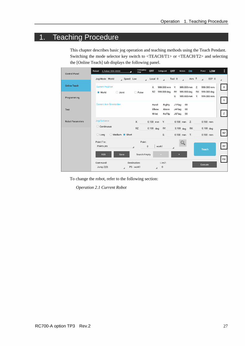
1. Teaching Procedure This chapter describes basic jog operation and teaching methods using the Teach Pendant. Switching the mode selector key switch to <TEACH/T1> or <TEACH/T2> and selecting the [Online Teach] tab displays the following panel.
To change the robot, refer to the following section:
Operation 2.1 Current Robot

Operation 1. Teaching Procedure
28 RC700-A option TP3 Rev.2
1.1 Jog Operation The robot can be moved to the teaching position by either of the following operation.
Step Jog operation Continuous Jog operation
1.1.1 Step Jog Operation
In Step Jog, the robot moves each time the Jog key is pressed. The jog distance has to be configured in [Jog Distance] beforehand (Long, Medium, and Short).
Reference: Operation 3.2.6 Jog Distance
Pressing the Jog key while holding the Enable Switch executes step jogs.
In Step Jog, the robot moves in one direction even if two keys are pressed at the same time. The robot does not move if more than three keys are pressed at the same time.
1.1.2 Continuous Jog Operation
In Continuous Jog, the robot moves while pressing the Jog key. Specify the jog distance to “Continuous” in the [Jog Distance].
Reference: Operation 3.2.6 Jog Distance
The continuous jog can be executed by pressing the Jog key while gripping the Enable Switch.
In Continuous Jog, the jog can be executed by pressing several jog keys at a time. For example, pressing the “+X” and “+Y” keys together executes a continuous jog diagonally. The robot does not move if more than three keys are pressed at the same time.
1.2 Teaching Teach the robot position to the specified point number.
(1) Specify the following items in the [Online Teach] panel.
[Point File] : Point file name [Point] : Point number
(2) Tap the <Teach> button. When the point number is already used, the message asking whether to overwrite the data will appear.
(3) Enter the point name and comment in the displayed message dialog box.
(4) Tap the <OK> button of the message dialog box to temporarily store the robot position.
(5) Press the <Save> button to save your changes.
NOTE
NOTE
Operation 1. Teaching Procedure
RC700-A option TP3 Rev.2 29
1.3 Direct Teaching “Direct teaching” is a method to teach the point directly by manually moving the SCARA robot while the motor of the joint to teach the point is off. Teach a position of the manually moved robot to the specified point number. (1) Select the [Control Panel] tab and move to the [Control Panel] panel.
(2) Turn off the motor of the joint to move in the [Free Joints]. De-energized joint can be moved manually.
(3) Select the [Online Teach] tab and move to the [Online Teach] panel.
(4) Move the robot arm to the position where you want to teach.
(5) Tap the < Teach> button.
If the point number is already used, the message asking whether to overwrite the data will appear.
(6) Enter the point name and comment in the message dialog box.
(7) Tap the <OK> button of the message dialog box to temporarily store the robot position.
(8) Tap the < Save> button to save your changes.

Operation 2. Common Functions
30 RC700-A option TP3 Rev.2
2. Common Functions This chapter describes common functions for all modes.
A
B
C
A: Selected robot can be checked.
Refer to: Operation 2.1 Current Robot
B: Status of emergency stop, safety door, motor, and power can be checked. Refer to: Operation 2.2 Status Bar
C: The sub menu can be displayed by tapping the menu button on the right. Refer to: Operation 2.3 Sub Menu
Operation 2. Common Functions
RC700-A option TP3 Rev.2 31
2.1 Current Robot Current robot number, name, and model are displayed.
To change the robot: Tap the panel to display the list, and select the robot to change.
The robot cannot be registered to the Controller by the Teach Pendant.
The robot can be changed in TEACH mode (TEACH/T1, TEACH/T2), but not in AUTO mode.
2.2 Status Bar This area displays the current robot status.
Name Description Value Emergency Stop Displays the emergency stop status
To release the emergency stop state, tap the <Reset> button. Refer to: Operation 3.1.3 Command Buttons
ON / OFF
Safeguard Displays the safety door status ON / OFF Motor Displays the robot motor status ON / OFF Power Displays the robot motor power status HIGH / LOW
Operation 2. Common Functions
32 RC700-A option TP3 Rev.2
2.3 Sub Menus Tapping the menu button on the upper right corner displays the sub menus. The displayed sub menus differ depending on the currently used panel.
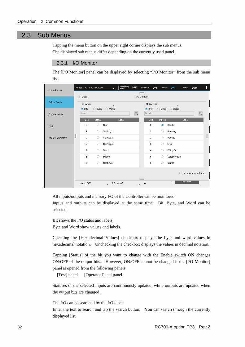
2.3.1 I/O Monitor
The [I/O Monitor] panel can be displayed by selecting “I/O Monitor” from the sub menu list.
All inputs/outputs and memory I/O of the Controller can be monitored. Inputs and outputs can be displayed at the same time. Bit, Byte, and Word can be selected. Bit shows the I/O status and labels. Byte and Word show values and labels. Checking the [Hexadecimal Values] checkbox displays the byte and word values in hexadecimal notation. Unchecking the checkbox displays the values in decimal notation. Tapping [Status] of the bit you want to change with the Enable switch ON changes ON/OFF of the output bits. However, ON/OFF cannot be changed if the [I/O Monitor] panel is opened from the following panels: [Test] panel [Operator Panel panel Statuses of the selected inputs are continuously updated, while outputs are updated when the output bits are changed. The I/O can be searched by the I/O label. Enter the text to search and tap the search button. You can search through the currently displayed list.

Operation 2. Common Functions
RC700-A option TP3 Rev.2 33
2.3.2 Robot 3D View
The [Robot 3D View] panel can be displayed by selecting “Robot 3D View” from the sub menu list.
The robot can be displayed in the 3D.
The coordinate axes and points are displayed on the same panel as the robot. This allows you to check the robot posture and motion from various points of view. Robot Display: One currently selected robot can be displayed. The display changes as you change the robot. Coordinate system display:
To display the coordinate system, tap either <Local>, <Tool>, or <ECP> to select the coordinate system you want to display and select the coordinate number. You can select several coordinate numbers.
Coordinate axes are displayed as follows: X axis: Green Y axis: Blue Z axis: Red
Point display:
To display the point, tap the <Point> button and select the point number from the current point file. You can select several points. The point can be displayed on the 3D display.

Operation 2. Common Functions
34 RC700-A option TP3 Rev.2
Field of View Control: Enlarge, reduce the panel : Tap the <+/−> button on the panel.
Rotate the view : Swipe with the <Camera> button ON.
Scroll the window : Swipe with the <Camera> button OFF.
Return to default : Tap the <Reset> button. Updating the display
Automatic and manual update can be selected. Tapping the Auto/Manual button switches between automatic update and manual update.
Auto : Automatically and periodically updates the display.
Manual : The display is updated by tapping the <Refresh> button.

Operation 2. Common Functions
RC700-A option TP3 Rev.2 35
2.3.3 Brake Setting
Selecting “Brake” from the sub menu list displays the [Brake] panel.
For the vertical 6-axis robots, the brake of each axis can be turned ON or OFF.
This is not available for non 6-axis robots.
The password entry panel will be displayed if the password is set. Enter the password and tap <OK> to display the [Brake] panel.
Brake ON: Check the checkboxes of the joints you want to lock the brakes. The brakes will be locked.
Brake OFF: Uncheck the checkboxes. The confirmation massage will appear when you uncheck the checkboxes. Read the message and tap <OK> to release the brakes. The joints can be moved by hands.

Operation 2. Common Functions
36 RC700-A option TP3 Rev.2
2.3.4 Command Window
Selecting “Command Window” from the sub menu list displays [Command] panel.
You can execute SPEL+ commands by the Robot Controller and check the results.
The panel is divided to Input and Output. Enter the SPEL+ commands and parameters in [Input] area. To execute the robot motion commands and I/O output commands, tap the <Enter> button with the Enable Switch ON.
Turning OFF the Enable Switch stops robot motion and returns to the [Command] panel.
To execute the commands other than robot motion commands and I/O output commands, tap the <Enter> button regardless of the Enable Switch status.
For details of the executable commands, refer to the following manual: EPSON RC+ Language Reference Appendix A: SPEL+ Command Use Condition List
The error message and error code are displayed in [Output] area in case of error.
The commands can be entered with both uppercase and lowercase characters. The following are descriptions for the buttons.
<Enter> : Sends the commands to the Controller. <Clear> : Clears the strings of either window. <All Clear> : Clears the strings of both windows.

Operation 2. Common Functions
RC700-A option TP3 Rev.2 37
2.3.5 Change Jog Key
Selecting “Change Jog Key” from the sub menu list enables you to change the axes corresponding to the hardware keys. When using the 7-axis robot, you can make the lower three sets of keys correspond with different axes. If the keys do not need to be changed, this menu cannot be selected. After changing the keys, the axes guide display will be updated.
Operation 2. Common Functions
38 RC700-A option TP3 Rev.2
2.3.6 Task Manager
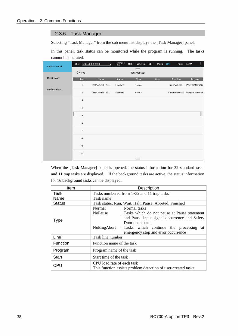
Selecting “Task Manager” from the sub menu list displays the [Task Manager] panel.
In this panel, task status can be monitored while the program is running. The tasks cannot be operated.
When the [Task Manager] panel is opened, the status information for 32 standard tasks and 11 trap tasks are displayed. If the background tasks are active, the status information for 16 background tasks can be displayed.
Item Description Task Tasks numbered from 1~32 and 11 trap tasks Name Task name Status Task status: Run, Wait, Halt, Pause, Aborted, Finished
Type
Normal : Normal tasks NoPause : Tasks which do not pause at Pause statement
and Pause input signal occurrence and Safety Door open state.
NoEmgAbort : Tasks which continue the processing at emergency stop and error occurrence
Line Task line number Function Function name of the task
Program Program name of the task
Start Start time of the task
CPU CPU load rate of each task This function assists problem detection of user-created tasks

Operation 2. Common Functions
RC700-A option TP3 Rev.2 39
2.3.7 System History
Selecting “System History” from the sub menu list displays the [System History] panel.
Displays events, errors, and warnings recorded in the current Controller system history.
Operation 2. Common Functions
40 RC700-A option TP3 Rev.2
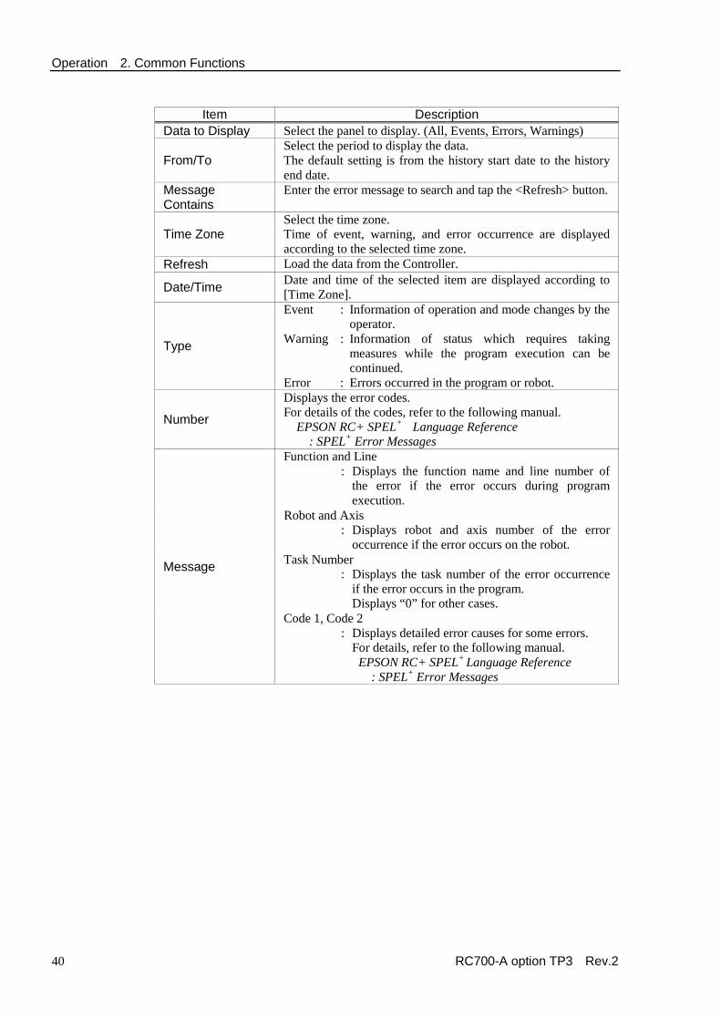
Item Description
Data to Display Select the panel to display. (All, Events, Errors, Warnings)
From/To Select the period to display the data. The default setting is from the history start date to the history end date.
Message Contains
Enter the error message to search and tap the <Refresh> button.
Time Zone Select the time zone. Time of event, warning, and error occurrence are displayed according to the selected time zone.
Refresh Load the data from the Controller.
Date/Time Date and time of the selected item are displayed according to [Time Zone].
Type
Event : Information of operation and mode changes by the operator.
Warning : Information of status which requires taking measures while the program execution can be continued.
Error : Errors occurred in the program or robot.
Number
Displays the error codes. For details of the codes, refer to the following manual.
EPSON RC+ SPEL+ Language Reference : SPEL+ Error Messages
Message
Function and Line : Displays the function name and line number of
the error if the error occurs during program execution.
Robot and Axis : Displays robot and axis number of the error
occurrence if the error occurs on the robot. Task Number : Displays the task number of the error occurrence
if the error occurs in the program. Displays “0” for other cases.
Code 1, Code 2 : Displays detailed error causes for some errors.
For details, refer to the following manual. EPSON RC+ SPEL+ Language Reference : SPEL+ Error Messages

Operation 2. Common Functions
RC700-A option TP3 Rev.2 41
2.4 Error Messages An error message appears when an error occurs. Example: A message displayed in the panel.
Example: A message displayed in a pop-up window.
Tapping <OK> closes the pop-up window and returns to the original panel.
Operation 3. TEACH/T1 Mode
42 RC700-A option TP3 Rev.2
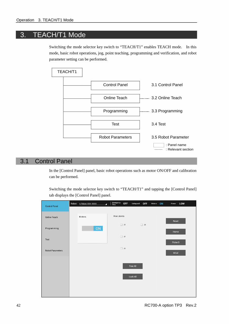
3. TEACH/T1 Mode Switching the mode selector key switch to “TEACH/T1” enables TEACH mode. In this mode, basic robot operations, jog, point teaching, programming and verification, and robot parameter setting can be performed.
TEACH/T1
Control Panel 3.1 Control Panel Online Teach 3.2 Online Teach Programming 3.3 Programming Test 3.4 Test Robot Parameters 3.5 Robot Parameter
: Panel name : Relevant section
3.1 Control Panel In the [Control Panel] panel, basic robot operations such as motor ON/OFF and calibration can be performed. Switching the mode selector key switch to “TEACH/T1” and tapping the [Control Panel] tab displays the [Control Panel] panel.
Operation 3. TEACH/T1 Mode
RC700-A option TP3 Rev.2 43
3.1.1 Motors
This button is used for turning ON or OFF all motors of the robot. Motor ON : Tap the <Motor> button with Motor OFF.
The confirmation window will appear. Tap the <OK> button. The motors will be ON.
Motor OFF : Tap the <Motor> button with Motor ON. The motors will be OFF immediately.
3.1.2 Free Joints
This group is used for turning ON or OFF the motors of joints individually. When teaching the SCARA robot by the direct teaching, turn off the motor of the joint.
This is not available for the vertical 6-axis robots. The following are descriptions for the buttons.
<J*> : Checking the checkbox of each joint releases the servo control. Unchecking the checkbox locks the servo control.
<Free All> : Releases the servo control of all joints.
<Lock All> : Locks the servo control of all joints.
3.1.3 Command Buttons
The buttons vary depending on the type of the selected robot. The following are descriptions for the buttons.
<Reset> : Resets the robot servo system and the emergency stop state.
<Home> : Moves the robot to the point specified by HomeSet command. This can be executed by pressing the <EXE.> key with the Enable Switch ON while the confirmation dialog is displayed.
<Pulse0> : Moves each joint to the 0 pulse position. This can be executed by pressing the <EXE.> key with the Enable Switch ON while the confirmation dialog is displayed.
<MCal> : Performs calibration (detect the mechanical home position). This can be executed by pressing the <EXE.> key with the Enable Switch ON while the confirmation dialog is displayed.

Operation 3. TEACH/T1 Mode
44 RC700-A option TP3 Rev.2
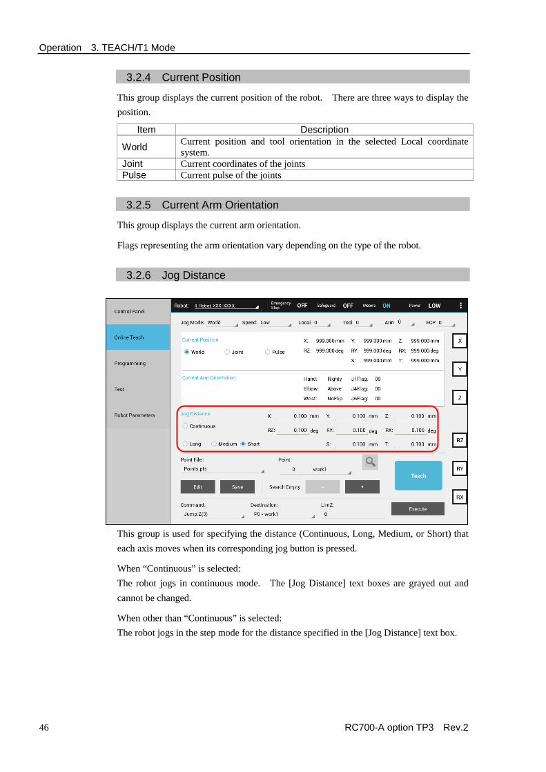
3.2 Online Teach
The [Online Teach] panel is used in teaching. Switching the mode selector key switch to “TEACH/T1” and tapping the [Online Teach] tab displays the [Online Teach] panel.
Jog key guide
Menu button
Tapping the upper right menu button displays the sub menus. For details of the panels displayed by selecting the menus, refer to the following.
[I/O Monitor] : Operation. 2.3.1 I/O Monitor [Robot 3D View] : Operation. 2.3.2 Robot 3D View [Brake] : Operation. 2.3.3 Brake Setting [Command Window] : Operation. 2.3.4 Command Window [Change Jog Key] : Operation. 2.3.5 Change Jog Key
In the [Online Teach] panel, the guide corresponding to the jog keys is displayed on the right end.

Operation 3. TEACH/T1 Mode
RC700-A option TP3 Rev.2 45
3.2.1 Mode
Select the jog mode. Item Description
World Jogs in current Local, Tool, arm and ECP coordinate systems. This is the default setting.
Tool Jogs in current Tool coordinate system. Local Jogs in current Local coordinate system. Joint Jogs each joint of the robot.
ECP Jogs in the coordinate system of the current external control point. This option is available when the ECP is enabled.
Key operation
World, Tool, Local, ECP: Jogs the robot along the X, Y, and Z axes. For robots with 4 DOF (Cartesian coordinate and SCARA), you can also jog U (roll). For robots with 6 DOF (vertical 6-axis), you can jog rotateZ (roll), rotateY (pitch), and rotateX (yaw) The guide display of the jog keys changes.
Joint: Jogs the robot using the keys from J1 (Joint #1) to J** (** is the number of joints). The guide display of the jog keys change to the joint numbers.
3.2.2 Speed
The speed for jogging and motion commands can be changed by selecting Low or High.
3.2.3 Coordinate System
The coordinate system to perform jogging and teaching can be selected from the user-defined coordinate systems.
Refer to: Operation 3.5 Robot Parameter
Item Description
Local Defined Local coordinate system 0 is same as the Base coordinate system.
Tool Defined Tool coordinate system
Arm
Arm coordinate system defined as the additional arm. This is available for the following robots.
Rectangular coordinate robots SCARA robots
ECP Defined coordinate system of the external control point. This is available when the external control point is enabled.
Operation 3. TEACH/T1 Mode
46 RC700-A option TP3 Rev.2
3.2.4 Current Position
This group displays the current position of the robot. There are three ways to display the position.
Item Description
World Current position and tool orientation in the selected Local coordinate system.
Joint Current coordinates of the joints Pulse Current pulse of the joints
3.2.5 Current Arm Orientation
This group displays the current arm orientation.
Flags representing the arm orientation vary depending on the type of the robot.
3.2.6 Jog Distance
This group is used for specifying the distance (Continuous, Long, Medium, or Short) that each axis moves when its corresponding jog button is pressed.
When “Continuous” is selected: The robot jogs in continuous mode. The [Jog Distance] text boxes are grayed out and cannot be changed.
When other than “Continuous” is selected: The robot jogs in the step mode for the distance specified in the [Jog Distance] text box.
Operation 3. TEACH/T1 Mode
RC700-A option TP3 Rev.2 47
[Jog Distance] text box changes according to the jog mode and the robot.
To change the values, select the jog distance to change and enter the new value. The change will be determined when the robot jogs after changing the value.
Distance Set Value* Default Value Short 0 to 10 0.1
Medium 0 to 30 1 Long More than 0 to 180 10
3.2.7 Registering the Robot Position
This group is used for registering the current robot position.
[Point File] : Select a point file.
[Point] : Select a point number.
<Teach> button : Registers the current robot position to the point number of the specified point file. The data will be saved to the memory.
<Save> button : Saves the data to the Controller.
<Edit> button : Switches to the point data editor where you can edit the points. Reference: Operation 3.3.4 Editing the Point Data
To search points:
Tap the search button to display the search window.
Enter a text to search, and then tap the downward (↓) or upward (↑) button to search with the point name.
Tapping the downward (↓) or upward (↑) button of the dead-number searches the nearest dead-number.
3.2.8 Command
This group executes the motion commands.
(1) Select the command name and parameters, and then tap the <Execute> button. The confirmation dialog box will appear.
(2) Press the <EXE.> key with the Enable Switch ON. The command is executed while the <EXE.> key is being pressed. The motion stops when either one or both of the Enable Switch and <EXE.> key is released.

Operation 3. TEACH/T1 Mode
48 RC700-A option TP3 Rev.2
3.2.9 Jog Key Guide
The current key assignment of the jog keys can be displayed.
The key assignment changes by a combination of following items, and the display changes accordingly.
Robot type Jog Mode Jog key change

Operation 3. TEACH/T1 Mode
RC700-A option TP3 Rev.2 49
3.3 Programming The following operations are available in the [Programming] panel.
Program editing Project build Point file management Point data editing
To display the [Programming] panel, switch the mode selector key switch to “TEACH/T1” and tap the [Programming] tab.
3.3.1 Current project management
The edited project can be built.
Tap the <Build> button. The message appears when the project is built properly.
If an error occurs, the line where the error occurred is shown in red.
3.3.2 Program editing
The program can be edited. Open, Close, Save, and Edit of the file are available.
To open the file, tap the file name in the file tree. Applicable files are program files (.prg) and include files (.inc).
You can open multiple files but can edit only one at a time.

Operation 3. TEACH/T1 Mode
50 RC700-A option TP3 Rev.2
Item Description Close Closes the active file.
The message appears if the file is being edited. The following options are available.
Save Close without saving Cancel
Save Save the active file.
3.3.3 Point file management
The point fine names are displayed in the tree.
Tapping the point file name in the file tree opens the file.
3.3.4 Point data editing
You can edit the point data of the point files.
Select the point file from the file tree to display the list of data.
Change the point data values:
(1) Tap the value to change to display the edit dialog panel.
(2) Enter the value.
(3) Tap <OK> to close the dialog window.
You can copy the value from the edit dialog window and paste it to another window. The menu of functions, such as copy, can be displayed by long-tapping the text input area of the edit dialog window.
To select the line, check the checkbox. You can select several lines.
To scroll, flick the table up and down.

Operation 3. TEACH/T1 Mode
RC700-A option TP3 Rev.2 51
Item Description Cut Cuts the data of the selected line. Copy Copies the data of the selected line.
Paste
Pastes the copied or cut data to the checked lines. The data will be overwritten. If the data copied or cut from the multiple lines are held, these will be pasted to the lines following the checked line.
Delete Line(s) Deletes the data of the selected lines. If several lines are selected, several point data will be deleted. The point numbers whose data is deleted will be dead-numbers.
Delete All Deletes all data. The file will be empty.
Save Saves changes to the Controller.
Restore Restores changes. The file will be restored to previous state.

Operation 3. TEACH/T1 Mode
52 RC700-A option TP3 Rev.2
3.4 Test In the [Test] panel, you can verify the program in TEST mode.
This mode enables program verification while the Enable Switch is held down and the safeguard is open. This is a low speed program verification function (T1: manual deceleration mode) which is defined in Safety Standards.
In this mode, you can execute the specified function with multi-task / single-task, multi-manipulator / single-manipulator at low speed.
The motors are turned OFF when the mode is changed from the TEST mode.
To display the [Test] panel, switch the mode selector key switch to “TEACH/T1”, and then tap the [Test] tab.
The following panels can be displayed from the sub menu list.
[Task Manager] : Reference Operation 2.3.6 Task Manager [I/O Monitor] : Reference Operation 2.31 I/O Monitor
The menu button cannot be used during program execution. Open the sub menu panels before starting the program or while it is paused.

Operation 3. TEACH/T1 Mode
RC700-A option TP3 Rev.2 53
3.4.1 Single-task program verification
The single-task program verification is used to verify a program in order to check the motion of the robot and peripherals by executing a single task with single- or multi-manipulators (Cycle / Step execution) while the safeguard is open. Function can be specified and executed within a speed limit.
To execute the program: Tap the operation key (Start, Continue, Step In, Step Over, and Walk), and then press the <EXE.> key while the Enable Switch is ON with the confirmation window open.
To stop the program temporarily: Release the Enable Switch or the <EXE.> key. The moving robot stops. (Quick Pause)
To resume the program: Tap the operation key (Continue, Step In, Step Over, and Walk), and then press the <EXE.> key while the Enable Switch is ON with the confirmation window open. The program will resume from the paused point.
To abort the program: Press the Emergency Stop switch. The program also aborts if an error occurs. The moving robot stops. (Quick Pause)
Pause by Open/Close status of the safeguard: The program pauses according to open/close status of the safeguard. The moving robot immediately stops. (Quick Pause)
To resume the program paused by Open/Close status of the safeguard: Release the latched status of the safeguard interlock. Then, tap the operation key (Continue, Step In, Step Over, and Walk) and press the <EXE.> key while the Enable Switch is ON with the confirmation window open.
WARNING
■ Before performing program verification, check that the robot system
operates normally by using the EPSON RC+ debug function.
For details on the EPSON RC+ debug function, refer to the EPSON RC+
User’s Guide.
If debugging is insufficient, the robot may cause unintended motion. This is
extremely hazardous and may cause serious bodily injury or severe damage
to the robot.
■ Before performing program verification, make sure that no one is in the
robot’s operation area.
The robot automatically starts moving as the program verification starts. If
the operator is in the robot’s operation area, it is extremely hazardous and
may cause serious bodily injury or severe damage to the robot.

Operation 3. TEACH/T1 Mode
54 RC700-A option TP3 Rev.2
CAUTION
■ When abnormal operation such as collision with peripherals is predicted, release
the <EXE.> key immediately and stop the robot.
The robot also can be stopped by releasing the Enable switch, or push the switch
harder.
■ After performing program verification, be sure to follow the points below:
- Check the changed parts in software before supplying power.
- Perform function test to check whether the robot system operates
normally.
In TEST mode, a program cannot be changed.
To change the point data, perform the following:
Teach the point in the [Online Teach] panel. Reference: Operation 3.2 Online Teach
Edit the point data in the [Programming] panel. Reference: Operation 3.3 Programming
Task Behavior during Single Task Program Verification: Background tasks stop when switching the mode to TEST mode. The tasks resume when switching to TEACH mode.
Behavior of Events and Tasks
Event Task Type Background Task Normal NoPause NoEmgAbort
Enable SW OFF Pause Pause Continue Continue Operation key is OFF (Continue, Step In, Step Over, and Walk)
Pause *1 *1 *2
STOP key is pressed Abort *1 *1 *2 Change Open/Close status of the Safety Door Pause *1 *1 *2
Error during a test Abort *1 *1 *2 Emergency stop Abort *1 *1 *2 Switch to TEACH mode Abort *1 *1 *2 *1 Xqt task types (NoPause, NoEmgAbort) cannot be executed.
When these tasks are specified, they are performed the program verification as normal tasks. *2 When background tasks are specified, they are performed the program verification as normal tasks.

Operation 3. TEACH/T1 Mode
RC700-A option TP3 Rev.2 55
Available Function: Functions with source not hidden
Robot Motion Speed Setting:
During the program verification, robots are always operated in Low power mode. Low power mode:
Speed lower than 250 mm/sec Restrains the motor power output
[Speed] can be changed within a range specified for Low power mode by pressing the <Speed> key.
Low: 25% of speed of Low power mode Middle: 50% of speed of Low power mode High: 100% of speed of Low power mode
CAUTION
The faster the speed, the longer the free running distance at the emergency stop or pause is. When operating the robot where interference with peripheral equipment is predictable, perform the program verification at low speed while taking the free running distance into consideration.
Execution-restraint Functions and Commands Power High : T1 mode
Power mode is always set to Low. Specification function cannot be executed.
T2 mode Specification function can be executed.
TRAP : Corresponding task cannot be executed even when a condition is met. XQT : An error occurs and the program execution will be aborted. INPUT : Input from the console causes an error and aborts the program execution. PRINT #20 : Output to the Teach Pendant causes an error and aborts the program
execution.
3.4.2 Multi-task Program Verification
The multi-task program verification is used to verify a program in order to check the motion of the robot and peripherals by executing a multiple task with single- or multi-manipulators (Cycle / Step execution) while the safeguard is open. Function can be specified and executed within a speed limit.
To execute the program: Tap the operation key (Start, Continue), and then press the <EXE.> key while the Enable Switch is ON with the confirmation window open.
To stop the program temporarily: Release the Enable Switch or the <EXE.> key. The moving robot stops. (Quick Pause)
Operation 3. TEACH/T1 Mode
56 RC700-A option TP3 Rev.2
To resume the program: Tap the operation key (Start, Continue), and then press the <EXE.> key while the Enable Switch is ON with the confirmation window open. The program will resume from the paused position.
To abort the program: Press the Emergency Stop switch. The program is also aborted when an error occurs. The moving robot stops. (Quick Pause)
Pause by Open/Close status of the safeguard: The program pauses according to open/close status of the safeguard. The moving robot immediately stops. (Quick Pause)
To resume the program paused by Open/Close status of the safeguard: Release the latched status of the safeguard interlock. Then, tap the operation key (Start, Continue) and press the <EXE.> key while the Enable Switch is ON with the confirmation window open.
WARNING
■ Before performing the program verification, check that the robot system operates normally by using the EPSON RC+ debug function.
For details on the EPSON RC+ debug function, refer to the EPSON RC+
User’s Guide.
If debugging is insufficient, the robot may cause unintended motion. This is
extremely hazardous and may cause serious bodily injury or severe damage to
the robot.
■ Before performing the program verification, make sure that no one is in the robot’s operation area.
The robot automatically starts moving as the program verification starts. If the
operator is in the robot’s operation area, it is extremely hazardous and may
cause serious bodily injury or severe damage to the robot.
CAUTION
■ When abnormal operation such as collision with peripherals is predicted, release the <EXE.> key immediately and stop the robot.
The robot also can be stopped by releasing the Enable Switch, or pushing the
switch harder.
■ After performing the program verification, be sure to follow the points below: - Check the changed parts in software before supplying power. - Perform the function test to check whether the robot system operates
normally.
Operation 3. TEACH/T1 Mode
RC700-A option TP3 Rev.2 57
In TEST mode, the program cannot be changed.
To change the point data, perform the following:
Teach the point in the [Online Teach] panel. Reference: Operation 3.2 Online Teach
Edit the point data in the [Programming] panel. Reference: Operation 3.3 Programming
Task Behavior during Multi-Task Program Verification Background tasks stop when switching the mode to the TEST mode. The tasks run automatically at the start of the program verification and are performed the verification along with specified normal tasks. These tasks stop when the multi-task program verification stops, and resume when switching to TEACH mode.
Behavior of Events and Tasks
Event Task Type Background Task Normal Normal NoPause NoEmgAbort
Enable SW is OFF Pause Pause Continue Continue Operation key is OFF (Continue, Step In, Step Over, and Walk)
Pause Pause Continue Continue
STOP key is pressed Abort Abort Abort Abort Change Open/Close status of the Safety Door Pause Pause Continue Continue
Error during a test Abort Abort Abort Abort Emergency stop Abort Abort Continue Abort Switch to TEACH mode Abort Abort Abort Continue/Resume
Available Function: Functions with source not hidden
Root Motion Speed Setting: During the program verification, robots are always operated in Low power mode.
Speed lower than 250 mm/sec Restrains the motor power output
[Speed] can be changed within a range specified for Low power mode by pressing the <Speed> key.
Low: 25% of speed of Low power mode Middle: 50% of speed of Low power mode High: 100% of speed of Low power mode
CAUTION
The faster the speed, the longer the free running distance in the emergency stop or pause is. When operating the robot where interference with peripheral equipment is predictable, perform the program verification at low speed while taking the free running distance into consideration.
Operation 3. TEACH/T1 Mode
58 RC700-A option TP3 Rev.2
Execution-restraint Functions and Commands: Power High : : T1 mode
Power mode is always set to Low. Specification function cannot be executed. T2 mode Specification function can be executed.
INPUT : Input from the console causes an error and aborts the program execution. PRINT #20 : Output to the Teach Pendant causes an error and aborts the program
execution.
3.4.3 TEST mode operation method
Select “Single-task/Multi-task” in TEST mode.
To open the file: Select the program file from [Program Files] tree and tap the file name. The program cannot be edited.
Verify the program: Select the “Function” to execute from the [Function] list and tap the operation key. The confirmation dialog window will appear. Hold the Enable Switch ON and press the <EXE.> key while the dialog window is open. If you want to execute and confirm a part of the motion, set a breakpoint and stop the program, and then execute the part by <Step In>, <Step Over>, or <Walk> button. Tapping the line number on the left sets or cancels the breakpoint.
Item Description Start Executes a task. Stop Stops the ongoing tasks. Continue Continues execution of the paused task from the current line.
Step In
Executes the current line of the paused task and stops at the next line. If the next line is a function call, the program stops at the beginning of the called function. This is available for the single-task program verification.
Step Over
Executes the current line of the paused task and stops at the next line. If the next line is a function call, the program stops after executing the called function. This is available for the single-task program verification.
Walk
Executes until the next motion command or output command, and then stops. You can configure whether to stop the program by the output command in the EPSON RC+. This is available for the single-task program verification.

Operation 3. TEACH/T1 Mode
RC700-A option TP3 Rev.2 59
3.5 Robot Parameters In the [Robot Parameters] panel, you can define the Local coordinate system and the Tool coordinate system, and configure the additional arms.
3.5.1 Local coordinate system setting
This panel is used for setting the Local coordinate system of the robot.
Select “Local” in [Function]. The values of the user-definable 15 Local coordinate systems will be displayed. Local “0” is the base coordinate system and cannot be changed in this panel. The base coordinate system can be changed by executing Base command from the command window. For details, refer to the following manual.
EPSON RC+ SPEL+ Language Reference The cells with no Local coordinate system definition are empty. Entering the value to the undefined Local coordinate system sets remaining cells to “0”. The Local coordinate systems numbering from 1 to 15 can be defined. Tapping the <Apply> button configures the Local coordinate system. For details of the Local setting, refer to the following manual.
EPSON RC+ SPEL+ Language Reference : Local Statement
NOTE

Operation 3. TEACH/T1 Mode
60 RC700-A option TP3 Rev.2
Item Description X The X coordinate of the local origin in the base coordinate system. Y The Y coordinate of the local origin in the base coordinate system. Z The Z coordinate of the local origin in the base coordinate system. U Rotation angle of the local about the base Z axis (roll). V Rotation angle of the local about the base Y axis (pitch). W Rotation angle of the local about the base X axis (yaw). Apply Applies the current values. Restore Restores the previous values. Clear Clears all values for the selected local.
3.5.2 Tool coordinate system setting
Select “Tool” in [Function]. The values of the user-definable 15 Tool coordinate systems will be displayed. The cells with no Tool coordinate system definition are empty. Entering the value to the undefined Tool coordinate system sets remaining cells to “0”. The Tool coordinate systems numbering from 1 to 15 can be defined. Tapping the <Apply> button configures the Tool coordinate system. For details of the Tool setting, refer to the following manual.
EPSON RC+ SPEL+ Language Reference : TLSet Statement
Item Description
X The X coordinate of the tool. Y The Y coordinate of the tool. Z Z offset of tool. U Rotation angle of the tool about the Z axis (roll). V Rotation angle of the tool about the Y axis (pitch). W Rotation angle of the tool about the X axis (yaw). Apply Sets the current values. Restore Restores the previous values Clear Clears all values for the selected tool.
Operation 3. TEACH/T1 Mode
RC700-A option TP3 Rev.2 61
3.5.3 Additional Arm setting
Select “Arm” in [Function]. The values of the user-definable 15 Arm will be displayed. This setting is not available for the vertical 6-axis robots and robots which do not support ArmSet command. The cells with no Arm definition are empty. Entering the value to undefined Arm sets remaining cells to “0”. Tapping the <Apply> button configures the additional Arm. For details of the Arm setting, refer to the following manual.
EPSON RC+ SPEL+ Language Reference : ArmSet Statement
Item Description
L2 Dist Distance between the center of Joint #2 and the center of the orientation joint in millimeters.
J2 Offset Angle of the line from the center of Joint #2 to the center of the orientation joint in degrees.
Z Offset The Z offset between the new orientation axis and the standard orientation axis.
L1 Dist Distance between the center of the shoulder joint and the center of the elbow joint in millimeters.
U Offset The angle offset between the standard orientation zero position and the new orientation axis zero position in degrees.
Apply Set current values. Restore Restore the previous values. Clear Clear all values for the selected arm

Operation 4. TEST/T2 Mode
62 RC700-A option TP3 Rev.2
4. TEACH/T2 Mode In TEACH/T2 mode, program verification in high speed is available in addition to the functions of TEACH/T1 mode.
TEACH/T2
Control Panel 3.1 Control Panel Online Teach 3.2 Online Teach Programming 3.3 Programming Test (T2) 4.1 Test (T2) Robot Parameters 3.5 Robot Parameters
: Panel name : Relevant section
Functions and operations are common in TEACH/T1 and TEACH/T2 except for “Test (T2)”.
This chapter only describes 4.1 Test (T2). For other functions and operations, refer to the following sections.
Operation 3.1 Control Panel Operation 3.2 Online Teach Operation 3.3 Programming Operation 3.5 Robot Parameters

Operation 4. TEST/T2 Mode
RC700-A option TP3 Rev.2 63
4.1 Test2 This mode enables the program verification while the Enable Switch is held down and the safeguard is open. This is a high speed program verification function (T2: manual acceleration mode) which is defined in Safety Standards.
In this mode, you can execute the specified function with multi-task / single-task, multi-manipulator / single-manipulator at high speed. The difference from T1 mode is a limiting speed.
The motors are turned OFF when the mode is changed from TEST mode.
To display the [Test (T2)] panel, switch the mode selector key switch to “TEACH/T2”, and then tap the [Test (T2)] tab. The password authentication window will appear. Enter the password and tap the <OK> button. Settable limiting speed is from 0 % (low speed) to 100 % (high speed).
The speed is set to low when the [Test (T2)] panel is opened. Also, the speed will be set to low if the Enable Switch is not operated for a certain time.
Other operating procedures are the same as “Test” except for the color of the panel.
Reference: Operation 3.4 Test The password for Test (T2) cannot be configured on the Teach pendant,. Set the password in the EPSON RC+.

Operation 5. AUTO Mode
64 RC700-A option TP3 Rev.2
5. AUTO Mode Switching the mode selector key switch to “Auto” enables AUTO mode. AUTO mode is used for the automatic operation (program execution) in on-site operation and state reference of the robot system. However, the robot cannot be operated and the program cannot be executed while the safety door is open. The robot cannot be changed.
Reference: Operation 2.1 Current Robot
AUTO
Operator Panel 5.1 Operator Panel
Maintenance 5.2 Maintenance Configuration 5.3 Configuration
: Panel name : Relevant section

Operation 5. AUTO Mode
RC700-A option TP3 Rev.2 65
5.1 Operator Panel
In the Operator Panel, you can execute and check the programs. To display the [Operator Panel] panel, switch the mode selector key switch to “AUTO” and tap the [Operator Panel] tab.
You can select the sub menus from the sub menu list which can be displayed by tapping the menu button. Selecting the sub menu displays the dialog accordingly. For details, refer to the following sections.
I/O Monitor : Operation 2.3.1 I/O Monitor Task Manager : Operation 2.3.6 Task Manager System History : Operation 2.3.7 System History
Operation 5. AUTO Mode
66 RC700-A option TP3 Rev.2
5.1.1 Program Execution
First, select “TP3” in the EPSON RC+ [Controller]-[Configuration]-[Control Device]. Then, turn ON the <Operate> button. Turning ON the button displays and enables the following buttons:
<Start> <Stop> <Pause> <Continue> Select the program of the current project from the [Program to run] list. You can operate the program by clicking the <Start>, <Stop>, <Pause>, and <Continue> buttons. The input/output window shows the output data. If an error occurs, the error information will be displayed.
Item Description Start Starts execution of the selected program. Stop Stops all tasks. Pause Stops all tasks which can be temporarily halted. Continue Resumes the suspended tasks.

Operation 5. AUTO Mode
RC700-A option TP3 Rev.2 67
5.2 Maintenance This panel is used for saving and displaying the data. To display the [Maintenance] panel, select the mode selector key switch to “AUTO”, and then tap the [Maintenance] tab.
Select either of the following from the [Function] list. Backup Restore
The password is required if it is set in the EPSON RC+. Enter the password.
5.2.1 Backup
This panel is used for saving the Controller information to the USB memory.
To save the current status: Tapping the <Backup> button saves the current state to the USB memory. The status such as controller setting, task status, I/O status, and robot status are saved. This is useful when reporting the controller status to the distributers or our technical support. The data is saved in the folder named “B_serial number_date_time”, which is automatically created under the EPSON folder in the USB.
To remove the USB memory: Tapping the <Unmount> button displays the removal instruction. Remove the USB memory by following the instruction.

Operation 5. AUTO Mode
68 RC700-A option TP3 Rev.2
5.2.2 Restore
This panel is used for restoring the controller configuration from the backup data saved in the USB memory. The Controller cannot be restored while the task is being executed. To restore Controller configuration:
(1) Insert the USB memory which contains the data to the Teach Pendant. (2) Tap the <Restore> button.
The [Browse for folder] panel will appear. (3) Select the data you want to restore from the [Browse for folder] panel. (4) Tap the <OK> button.
The [Browse for folder] panel closes and the [Restore Controller] panel will appear. (5) Check the information to restore in the [Restore Controller] panel. (6) Tap the <OK> button.
The data restoration will start.
If the current Controller configuration and that of the backup data differ, a warning message will appear. Restoration must be performed on the same system. The Controller restarts after restoring the data.
To remove the USB memory:
Tapping the <Unmount> button displays the removal instruction. Remove the USB memory by following the instruction.

Operation 5. AUTO Mode
RC700-A option TP3 Rev.2 69
5.3 Configuration This panel is used for various settings. To display the [Configuration] panel, switch the mode selector key switch to “AUTO” and tap the [Configuration] tab.
Select either of the following from the [Function] list. Preferences System Information Update Firmware Shutdown 5.3.1 Preferences
Following settings are available. Language : Selects the language for the display and keypad.
Available languages are Japanese, English, French, German, Simplified Chinese, and Traditional Chinese. The application automatically restarts when the language is changed.
LCD settings : Sets brightness of the LCD. Move the slider to set appropriate brightness.
Speaker : Sets the speaker volume. Move the slider to set appropriate volume.

Operation 5. AUTO Mode
70 RC700-A option TP3 Rev.2
5.3.2 System Information
This panel displays the Controller and Teach pendant information. Controller information
Controller Name : Name of the Controller Serial Number : Controller serial number Firmware Version : Controller firmware version
Terminal device information: Firmware Version : Teach pendant firmware version Application Version : Teach Pendant application version 5.3.3 Update Firmware
In this panel, you can update the Teach Pendant firmware. The following two items are required for updating.
- USB memory with sufficient capacity - PC to write the update file from the Installation DVD to the USB memory
Preparation
(1) Insert the USB memory to PC.
(2) Insert the Installation DVD to PC. The wizard automatically starts.
(3) Following the wizard, copy the update file from the Installation DVD to the USB memory.

Operation 5. AUTO Mode
RC700-A option TP3 Rev.2 71
Update
(1) Insert the USB memory to the USB port (lower) on the Teach Pendant.
(2) After the USB memory is recognized, tap the <Update> button of [Configuration] panel.
(3) After the confirmation window is displayed, tap the <OK> button and start update.
Update will complete in a few minutes. To remove the USB memory, tap the <Unmount> button and follow the instruction.
The current version can be checked in [System Information]. Reference: Operation 5.3.2 System Information
CAUTION
■ Do not remove the Teach Pendant power cable and USB memory while updating software. Teach Pendant and USB memory may be damaged.
■ Do not operate the robot while updating software. The firmware may be damaged and the system may not start.
The USB with security function cannot be used.
5.3.4 Shutdown
In this panel, you can shut down the Teach Pendant system. Tapping the <Execute> button starts shutdown processing. The following operations stop power supply to the Teach Pendant. Before conducting the following operations, make sure to shut down the Teach Pendant system.
When turning off the Controller When removing the Teach Pendant from the Controller
Operation 6. Password Setup
72 RC700-A option TP3 Rev.2
6. Password Setup You can set a password to restrict operators to use the following functions.
Brake function (6-axis robot only) Maintenance Test (T2) function
Set the password in the EPSON RC+.
Operation 7. Troubleshooting
RC700-A option TP3 Rev.2 73
7. Troubleshooting If the condition does not change after performing the countermeasure, the unit may have suffered a breakdown. Please contact the service center or the manufacturer.
Display panel is blank
- The Controller supplies 24VDC. Check that the Controller is ON.
- Check that the Controller is connected to the TP port of the Controller properly.
An Error code appears and the Robot does not operate normally
- Please refer to the error code in the following manual.
EPSON RC+ SPEL+ Language Reference
Robot does not move by pressing the Jog key
- Execute the Motor On command to energize the Robot motor. For details, refer to the following manual:
EPSON RC+ SPEL+ Language Reference: Motor
- Energize the Robot motor. For details, refer to the following manual:
EPSON RC+ SPEL+ Language Reference: SLock
- Short jog distance may be selected. Check the value in the [Jog Distance] and change the setting to long distance if needed. For details, refer to the following section:
Operation 3.2.6 Jog Distance
Operation mode does not switch from TEACH mode to AUTO mode - Turn ON the latch release input of the EMERGENCY connector to release the latch
status.
Program list is not displayed in program verification window of TEST
mode - Check for the setting whether it is set to store execution source files to the Controller.
Settings can be confirmed by following steps:
Select EPSON RC+ menu- [Project]-[Properties]-[Source Files In Controller] and check if desired files are checked in [Select source files to store in controller:].

Operation 8. Maintenance Parts List
74 RC700-A option TP3 Rev.2
8. Maintenance Parts List Part Name Code Note
Wall Bracket R12NZ900NH
Option Extension Cable
10m R12NZ900NJ
15m R12NZ900NK