RoboCup Logistics League sponsored by Festo
28
RoboCup Logistics League sponsored by Festo Rules and Regulations 2013 The Technical Committee Revision Date: 2013-06-05 19:31:08 +0200 (Mi, 05. Jun 2013)
Transcript of RoboCup Logistics League sponsored by Festo
RoboCup Logistics League sponsored by Festo
Rules and Regulations 2013
The Technical Committee
Revision Date: 2013-06-05 19:31:08 +0200 (Mi, 05. Jun 2013)
Contents1 Introduction 1
1.1 The task . . . . . . . . . . . . . . . . . . . . . . . . . . . . . . . . . . . . . . . . . . . 11.2 Agreements & regulations . . . . . . . . . . . . . . . . . . . . . . . . . . . . . . . . . 2
2 League administration 22.1 Technical Committee 2013 . . . . . . . . . . . . . . . . . . . . . . . . . . . . . . . . 22.2 Organizing Committee 2013 . . . . . . . . . . . . . . . . . . . . . . . . . . . . . . . 2
3 Competition Area 23.1 Field dimensions . . . . . . . . . . . . . . . . . . . . . . . . . . . . . . . . . . . . . . 23.2 Coordinates of the Machines and Field Slots . . . . . . . . . . . . . . . . . . . . . . 33.3 The pallet carrier puck . . . . . . . . . . . . . . . . . . . . . . . . . . . . . . . . . . . 33.4 Machines . . . . . . . . . . . . . . . . . . . . . . . . . . . . . . . . . . . . . . . . . . 3
3.4.1 General information . . . . . . . . . . . . . . . . . . . . . . . . . . . . . . . . 33.4.2 Production machines — during exploration phase . . . . . . . . . . . . . . . 43.4.3 Production machines — during production phase . . . . . . . . . . . . . . . 53.4.4 Recycling unit . . . . . . . . . . . . . . . . . . . . . . . . . . . . . . . . . . . 73.4.5 Delivery gates . . . . . . . . . . . . . . . . . . . . . . . . . . . . . . . . . . . 73.4.6 Test station . . . . . . . . . . . . . . . . . . . . . . . . . . . . . . . . . . . . . 8
4 The Robotino system 84.1 Markings . . . . . . . . . . . . . . . . . . . . . . . . . . . . . . . . . . . . . . . . . . 8
5 Communication 95.1 Bandwidth allocation . . . . . . . . . . . . . . . . . . . . . . . . . . . . . . . . . . . . 95.2 Referee box . . . . . . . . . . . . . . . . . . . . . . . . . . . . . . . . . . . . . . . . . 95.3 Remote control . . . . . . . . . . . . . . . . . . . . . . . . . . . . . . . . . . . . . . . 105.4 Monitoring . . . . . . . . . . . . . . . . . . . . . . . . . . . . . . . . . . . . . . . . . 105.5 Inter-robot communication . . . . . . . . . . . . . . . . . . . . . . . . . . . . . . . . 105.6 Communication eavesdropping and interference . . . . . . . . . . . . . . . . . . . . 105.7 Wifi regulations . . . . . . . . . . . . . . . . . . . . . . . . . . . . . . . . . . . . . . . 10
6 Game play 106.1 Environment setup . . . . . . . . . . . . . . . . . . . . . . . . . . . . . . . . . . . . . 116.2 Game phases . . . . . . . . . . . . . . . . . . . . . . . . . . . . . . . . . . . . . . . . 11
6.2.1 Team setup . . . . . . . . . . . . . . . . . . . . . . . . . . . . . . . . . . . . . 116.2.2 Interruptions and robot maintenance . . . . . . . . . . . . . . . . . . . . . . 116.2.3 Game start . . . . . . . . . . . . . . . . . . . . . . . . . . . . . . . . . . . . . 126.2.4 Exploration phase . . . . . . . . . . . . . . . . . . . . . . . . . . . . . . . . . 126.2.5 Production phase . . . . . . . . . . . . . . . . . . . . . . . . . . . . . . . . . 12
6.3 Production portfolio . . . . . . . . . . . . . . . . . . . . . . . . . . . . . . . . . . . . 126.3.1 The production table . . . . . . . . . . . . . . . . . . . . . . . . . . . . . . . 136.3.2 Late order . . . . . . . . . . . . . . . . . . . . . . . . . . . . . . . . . . . . . 13
6.4 During a match . . . . . . . . . . . . . . . . . . . . . . . . . . . . . . . . . . . . . . . 14
6.4.1 Out-of-order . . . . . . . . . . . . . . . . . . . . . . . . . . . . . . . . . . . . 146.4.2 Production Plan . . . . . . . . . . . . . . . . . . . . . . . . . . . . . . . . . . 14
7 Tournament 147.1 Tournament Scoring Specifications . . . . . . . . . . . . . . . . . . . . . . . . . . . . 147.2 Task fulfillment . . . . . . . . . . . . . . . . . . . . . . . . . . . . . . . . . . . . . . . 167.3 Penalties . . . . . . . . . . . . . . . . . . . . . . . . . . . . . . . . . . . . . . . . . . . 167.4 Technical Challenge . . . . . . . . . . . . . . . . . . . . . . . . . . . . . . . . . . . . 18
A Engineering Reference 20A.1 The Mobile Robot System . . . . . . . . . . . . . . . . . . . . . . . . . . . . . . . . . 20
A.1.1 Robot Dimensions . . . . . . . . . . . . . . . . . . . . . . . . . . . . . . . . . 20A.1.2 Drive Unit . . . . . . . . . . . . . . . . . . . . . . . . . . . . . . . . . . . . . 20A.1.3 Sensors . . . . . . . . . . . . . . . . . . . . . . . . . . . . . . . . . . . . . . . 21A.1.4 Controller Board – 2010 Revision . . . . . . . . . . . . . . . . . . . . . . . . 21A.1.5 Software . . . . . . . . . . . . . . . . . . . . . . . . . . . . . . . . . . . . . . 22
A.2 Machines . . . . . . . . . . . . . . . . . . . . . . . . . . . . . . . . . . . . . . . . . . 23A.2.1 Brackets . . . . . . . . . . . . . . . . . . . . . . . . . . . . . . . . . . . . . . 23A.2.2 Signal . . . . . . . . . . . . . . . . . . . . . . . . . . . . . . . . . . . . . . . . 24A.2.3 RFID device . . . . . . . . . . . . . . . . . . . . . . . . . . . . . . . . . . . . 24A.2.4 Wifi equipment . . . . . . . . . . . . . . . . . . . . . . . . . . . . . . . . . . 25A.2.5 Data carrier . . . . . . . . . . . . . . . . . . . . . . . . . . . . . . . . . . . . 25
ii
1 Introduction
PreambleThe future of Production Industry lies with smarter systems. With current developments pursuingthe goal of more aware, more decentralized behaviors in factories, a scientific platform for ap-plied research is required. The RoboCup Logistics League sponsored by Festo is determined todevelop into a state-of-the-art platform for mobile robotics education. This industrial motivatedleague keeps the focus on challenges promoting precise actions, further encouraging external datasupported autonomy.
This year’s competition environment is laid out in the pages to come. It ensures the same andfair circumstances for all participants, it however is neither meant to dictate nor suggest the wayhow to fulfill the task, but is meant to develop the Logistics League further towards deployingAutomated Guided Vehicles in industrial applications. This includes current challenges of devel-oping industry-wide standards for Cyber Physical Systems for production processes like designingplug-and-produce capable systems.
After an exciting RoboCup in Mexico, we look forward to a new scale of competition that willemerge from initiatives around the globe. In 2012 we had our first Logistics League World Cham-pion. In 2013 we introduce the Referee Box changing the competition at its core by introducinga flow of information. This allows for more dynamic games and the automatic tracking of scores,and to relax the hitherto existing regulations regarding additional computing power.
Finally, no rulebook is perfect. Feel obliged to inform us about issues you like to discuss or gapsthat might have an impact on the competition, so we can keep the necessity for rule discussions atthe RoboCup event to a minimum. We are open for all kinds of suggestions; the set of rules willbe fixed at 01/01/2013 and revised in April 2013 after the German Open 2013 competition.
1.1 The taskOur aim is to simulate autonomous guided vehicles in industrial applications. In opposition to reg-ular automatic guided vehicles teams shall complete the following task without human interferenceas successful as possible, competing with a second team against the clock.
The Logistics League’s main challenge is a multistage production cycle of different productvariants with self-crafted intermediate products and delivery of the final product. This genuinegoal will be rewarded considerably higher than partial fulfillment of the task. Autonomous robotstransport hockey pucks which act as a placeholder for (intermediate) products between the pro-cessing machines. A machine can basically be understood as a signal light with an attached RFIDreader as described in Appendix A. Each puck carries an ID tag which will be read and pro-cessed according to the related machine’s specification. If procurable this will lead to a new puckstate: a new sub-assembly is produced or prepared. Complete work orders require all related sub-assemblies of product variants (cf. Section 6.3 for details). Such transformations can rely on morethan one puck as input to be triggered.
This work flow is controlled by a referee box broadcasting information via wifi (see Sec-tion 5.2). The work flow itself is divided into three different phases: a short setup phase, anexploration phase (see Section 6.2.4) during which robots receive scores for correctly discoveringand publishing the yet unknown types of the different machines on the field. After this phase thereferee box will announce all machine types and designations. Succeeding into the second game
1

phase the actual production tasks as described in detail in Section 6.2.5 is disclosed to the teamsand their robots.
The whole factory area can be used as an intermediate storage. Finally successfully assembledproducts are to be delivered to the correct delivery gate and get unloaded into its delivery slot. Thefactory area has to be treated in the best possible way. Any possible damage to the field or themachines will be penalized by the referee.
1.2 Agreements & regulationsThe Logistics League follows a certain design philosophy. All teams are obliged to use theRobotino robotic system from Festo Didactic GmbH & Co. KG with certain freedoms and limi-tations. The usage of all currently publicly available revisions is in order, see Section 4 and Ap-pendix A for further details. All available sensor equipment that does neither exceed Robotino’sdiameter (see Appendix A.1.1) nor require external assistance (like Indoor GPS) is permitted.
2 League administration
2.1 Technical Committee 2013Christian Deppe, Otto-von-Guericke University Magdeburg, Magdeburg, GermanyDaniel Ewert, RWTH Aachen University, Aachen, GermanySören Jentzsch, Technical University of Munich, Munich, GermanyTim Niemueller, RWTH Aachen University, Aachen, GermanySebastian Reuter, RWTH Aachen University, Aachen, Germany
To get into contact with the TC use the mailing [email protected]
2.2 Organizing Committee 2013Alexander Ferrein, FH Aachen University of Applied Sciences, Aachen, GermanyUlrich Karras, Festo Didactic GmbH, Denkendorf, GermanyGuilherme Cano Lopes, UNESP - São Paulo State University, São Paulo, BrazilAlexander Ratai, TU Magdeburg, Magdeburg, GermanySebastian Reuter, RWTH Aachen University, Aachen, Germany
To get into contact with the OC use the mailing [email protected]
3 Competition Area
3.1 Field dimensionsThe point of origin for each statement within this rulebook that uses relative coordinates is thebottom left corner of the competition area namely the corner near robot insertion area below theblue input storage area. All indicated sizes of mark-ups are to be considered outside dimensions.
2

The competition area is a 5.6 m×5.6 m large arena with several RFID-mounted machines,mark-ups, a stock of raw-material and a delivery zone. It is surrounded by boards, 0.5 m of heightto reduce object interference from outside the area. The default width for mark-ups is 19 mm, thedefault color is black.
The factory area spans across 4.8 m×5.6 m. There are two boundaries, set by two mark-ups,0.4 m from the left and right borders of the competition area. The factory area is joined by twoopposing 0.4 m×1.0 m zones at the left and right middle. The left zone is painted blue markingthe input storage area with the late order insertion point to the top. The insertion area is 0.6 m ofdepth with the insertion slot in its middle. This spot is a 0.1 m×0.1 m empty square that will beequipped with a pallet carrier to start the late order challenge. The space below the input storagearea is called robot insertion area.
The right zone is marked green and houses the three delivery gates. Each gate is of 0.3 m widthwith 0.1 m space to the next delivery gate separated by black mark-ups.
The delivery gates feature one signal per gate placed in the middle of each gate zone. Thedelivery slot resides besides a unit that is identical in construction to a production machine. Eachof the three RFID devices within these gates feature a black centered square of 0.1 m×0.1 m calleddelivery slot, which resides exactly below the RFID device.
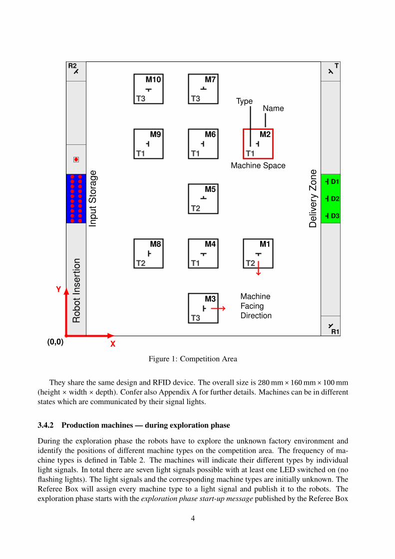
Additionally to the delivery gates, 13 machines are placed within the competition area: 10machines representing the multistaged production process, two machines to recycle consumedpallet carrier and one test station. The machines of the production process are placed within thefactory area as stated in Figure 1. They are aligned in a 90° angle (the facing direction may changeduring the tournament). Each production machine resides in the center of a squared machine spacespanned by standard mark-ups with 0.6 m each side.
The 3 additional machines are arranged in the corners of the competition area, and aligned at45°, facing the center of the factory area. The lower left corner will remain empty. The competitionarea is shown in Figure 1.
3.2 Coordinates of the Machines and Field SlotsThe coordinates of the machine centers and the centers of the different field slots are presented inTable 1.
3.3 The pallet carrier puckThe data-carrying RFID tag is attached on top of a hockey puck. Each pallet carrier can be iden-tified by a unique number. The tournament puck features a diameter of 7.5 cm and is shown inFigure 2. Please consult Appendix A.2.5 for further information of the RFID tag.
3.4 Machines3.4.1 General information
All machines are identical devices consisting of
• one plate housing the RFID read/write device and
• one signal unit according to Figure 3.
3
X
Y
(0,0)
M1
T2
M2
T1
M3
T3
M4
T1
M5
T2
M6
T1
M7
T3
M8
T2
M9
T1
M10
T3
D1
D2
D3
R1
R2 T
Rob
otIn
sert
ion
Inpu
tSto
rage
Machine Space
Del
iver
yZo
ne
MachineFacingDirection
NameType
Figure 1: Competition Area
They share the same design and RFID device. The overall size is 280 mm×160 mm×100 mm(height × width × depth). Confer also Appendix A for further details. Machines can be in differentstates which are communicated by their signal lights.
3.4.2 Production machines — during exploration phase
During the exploration phase the robots have to explore the unknown factory environment andidentify the positions of different machine types on the competition area. The frequency of ma-chine types is defined in Table 2. The machines will indicate their different types by individuallight signals. In total there are seven light signals possible with at least one LED switched on (noflashing lights). The light signals and the corresponding machine types are initially unknown. TheReferee Box will assign every machine type to a light signal and publish it to the robots. Theexploration phase starts with the exploration phase start-up message published by the Referee Box
4

Abbr. Unit x [m] y [m]M1 Machine 1 3.92 1.68M2 Machine 2 3.92 3.92M3 Machine 3 2.80 0.56M4 Machine 4 2.80 1.68M5 Machine 5 2.80 2.80M6 Machine 6 2.80 3.92M7 Machine 7 2.80 5.04M8 Machine 8 1.68 1.68M9 Machine 9 1.68 3.92M10 Machine 10 1.68 5.04R1 Recycling unit 1 5.40 0.20R2 Recycling unit 2 0.20 5.40T Test station 5.40 5.40
Late order insertion point / slot 0.20 3.60D1 Delivery slot 1 5.34 3.15D2 Delivery slot 2 5.34 2.80D3 Delivery slot 3 5.34 2.45
Table 1: Coordinates of machines and field slots
Figure 2: Puck
Figure 3: Machine
which defines the light signals of the machine types, e.g., red and green LED switched on indicatemachine type T1. If a robot perceives the red and green LED light switched on at machine M1, therobot has to announce that machine M1 is of type T1 to the Referee Box. Therefore, the robot hasto send a machine identified message to the Referee Box. Please consult the RoboCup LogisticsLeague Referee Box Specification for a detailed definition of the message types.
3.4.3 Production machines — during production phase
The default operating mode of all machines implies that only the green LED is turned on. Thissignals that the machine is ready for input. To enable the production process it is necessary totransport the pallet carrier accurately to the RFID device.
If a (intermediate) product is fed into a machine, the machine reads the RFID tag and checkswhether or not the product can be processed and induces the result by its signal light. If an ap-propriate product is fed to the machine, the yellow LED turns on indicating that the machine isprocessing the product (green and yellow LED on). If the machine needs another sub-assemblyto generate an output, the green LED turns off and the yellow light indicates that the machine iswaiting for the next sub-assembly. A consumed pallet carrier has to stay within the machine spaceborders (no part of the puck being outside the mark-up) until the production cycle of that verymachine has been completed. Products resulting from violating this requirement are consideredjunk and will not be rewarded.
If the yellow LED is turned off after processing, further input materials are fed to the ma-chine, the green LED indicates that the machine has finished the work order and the last carrier istransformed to its corresponding output.
If a product is fed to a machine which is not appropriate, the machine reacts with a yellow light
5

Optical Feedback Operating modeAll LEDs turned off The machine is physically offline, caused by a real error
which should not happen during the competition.Red LED turned on The machine is out of order.Green LED turned on The machine is idle and ready.Green and yellow LED turned on The machine is processing or consuming the current data
carrier.Yellow LED flashing (at 2 Hz) The machine detects wrong material. This can be caused
by data carriers that are already consumed, sub-assembliesthat do not fit to this machine type’s work order or cor-rupted data carriers.
(a) Optical Feedback during production phase
Type Distribution Input Output (Final)processing time[s]T1 4 times S0 (raw-material) S1 t1 = 3 to 8 secT2 3 times S0; S1 S2; one consumed
containert2 = 15 to 25 sec
T3 1 times S0; S1; S2 P1; two consumedcontainers
t3 = 40 to 60 sec
T4 1 times S0; S1; S2 P2; two consumedcontainers
t4 = 40 to 60 sec
T5 1 times S0 P3 t5 = 20 to 40 sec
(b) Machine Types
Table 2: Production Machines
flashing at 2 Hz. A red light indicates that the machine is in an error state. In this case no productscan be processed on the machine. Table 2 summarizes the operating modes of the productionmachines and the corresponding signal lights.
The machine always processes the required pallet carrier delivered last, all prior componentswill be consumed. All machines will start processing the data carrier as soon as it enters themachine zone as stated in section 3.1. They will change their operating mode according to Tables 2to 5.
In order to complete the machines’ work order the input materials have to be delivered one-by-one into the RFID device’s action range. The sequence of delivered input materials is irrelevant(e.g., S0-S1 or S1-S0). Multiple data carriers in range of the device will result in erroneous behaviorof the device. Consumption of materials, such as S0 used in the production of S2, will take 2seconds. Unloading the machine can be done immediately after the operating mode changes awayfrom processing. As long as the machines are used properly, they will not produce any junk.The distribution describes how many machines of the respective types will be randomly placedresulting in a total of 10 court machines.
6
Optical Feedback Operating modeAll LEDs turned off The machine is physically offline, caused by a real error
which should not happen during the competition.Red LED turned on The machine is out of orderGreen LED turned on The machine is idle and ready.Green and yellow LED turned on The machine is processing the current data carrier.
Table 3: Recycling Unit
Optical Feedback Stored data on the data carrierRed turned on This delivery gate is inactive.Green turned on This gate is active, namely the designated gate.Yellow blinking False deliver to active gate.Red on, Yellow flashing (at 2 Hz) False delivery to inactive gate. The puck’s state changes to
consumed.Red, Yellow, Green turned on Successful delivery
Table 4: Delivery Gates
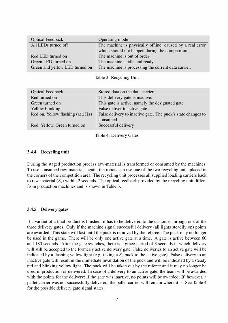
3.4.4 Recycling unit
During the staged production process raw-material is transformed or consumed by the machines.To use consumed raw-materials again, the robots can use one of the two recycling units placed inthe corners of the competition area. The recycling unit processes all supplied loading carriers backto raw-material (S0) within 2 seconds. The optical feedback provided by the recycling unit differsfrom production machines and is shown in Table 3.
3.4.5 Delivery gates
If a variant of a final product is finished, it has to be delivered to the customer through one of thethree delivery gates. Only if the machine signal successful delivery (all lights steadily on) pointsare awarded. This state will last until the puck is removed by the referee. The puck may no longerbe used in the game. There will be only one active gate at a time. A gate is active between 60and 180 seconds. After the gate switches, there is a grace period of 3 seconds in which deliverywill still be accepted to the formerly active delivery gate. False deliveries to an active gate will beindicated by a flashing yellow light (e.g. taking a S0 puck to the active gate). False delivery to aninactive gate will result in the immediate invalidation of the puck and will be indicated by a steadyred and blinking yellow light. The puck will be taken out by the referee and it may no longer beused in production or delivered. In case of a delivery to an active gate, the team will be awardedwith the points for the delivery; if the gate was inactive, no points will be awarded. If, however, apallet carrier was not successfully delivered, the pallet carrier will remain where it is. See Table 4for the possible delivery gate signal states.
7

Optical Feedback Stored data on the data carrierGreen LED turned on The station is ready to read the next data carrier.All LEDs turned off Consumed pallet carrier.Yellow LED turned on Raw-material (S0)Red and yellow LEDs turned on Sub-assembly 1 (S1)Red LED turned on Sub-assembly 2 (S2)Green LED flashing (at 2 Hz) Finished product variant 1 (P1)Yellow LED flashing (at 2 Hz) Finished product variant 2 (P2)Red LED flashing (at 2 Hz) Finished product variant 3 (P3)
Table 5: Test Station
3.4.6 Test station
The type of a sub-assembly can be determined at the test station in the corresponding corner of thecompetition area. The test station reads the RFID of the pallet carrier and visualizes the producttype with the light signal as shown in Table 5.
4 The Robotino systemAll participants have to design their competition Robotinos within the following specifications.For a detailed technical description of the basic hardware, refer to the Appendix A.
Any kind of sensors can be changed or added to the Robotino platform. However, it is notpossible to implement sensors that require modifications outside the Robotino area (e.g. Northstar,indoor GPS). It is furthermore strictly forbidden to implement any kind of RFID device into theRobotino. There must be no changes to the controller or mechanical system. The pushing deviceis defined as a passive, non-mechanical load handling attachment. The robots peripherals must notexceed the maximum total height of 0.7 m. Additional hardware (sensors, computing equipment,etc.) must be within a diameter of 0.6 m centered at the robot’s rotational center. Additionalhardware may only occupy up to 25% of this additional 0.1 cm wide ring around the robot. Theonly additional actuator allowed is one pushing device for pucks which can be the original or amodified one. It however must not exceed the following outside dimensions (including possiblyadded sensors): 0.25 m×0.15 m×0.05 m (width × depth × height). The puck must be visible fromabove while inside the pushing device.
It is allowed to install additional computing power on the Robotino. This may either be inform of a notebook/laptop device or any other computing device that suits the size requirement ofthe Robotino competition system. Furthermore, it is allowed to communicate with an additionalcomputing device off-field. This device may be used for team coordination and/or other purposes.However, communication among the robots and the off-field device is not guaranteed during thecompetition.
4.1 MarkingsAll field robots must be assigned a single unique number out of the set {1,2,3}. The numbermust be written on the robot in one or more places and clearly visible from all directions, e.g.
8

printed adhesive labels placed on top or the sides of the robot. The number must be the same as isannounced in the beacon signal to the referee box (cf. Section 5.2).
To allow identification by the overhead camera system of the referee box, all robots mustwear unique colored labels on top of the robot. The labels will be provided by the organizingcommittee. Teams must provide appropriate mounting capabilities such that the labels are freelyand completely visible from above. The marker in 2013 will be round labels of approximately20 cm in diameter printed on paperboard.
5 CommunicationRobots have to operate autonomously, that is, without any human interference during the game.Communication among robots and to off-board computing units is allowed only using wifi (cf. Sec-tion 5.7). Communication is not guaranteed and may be unavailable during parts of the game.Interruptions must be expected and are no reason to pause or abort a game, even if they endure forlong periods of the game.
5.1 Bandwidth allocationNo minimum bandwidth is guaranteed. The amount of communicated data over the wifi connectionshall not exceed 2 Mbit/s. Even though the lower layers could provide for more bandwidth, theoverall available frequency spectrum and wifi channels have to be shared, not only within ourown league. Generally, a conservative use of bandwidth resources is advised. Should a frequentlyor endured exceedance of the bandwidth limit become known, or if the overall bandwidth limitmust be reduced due to outer circumstances, the TC can monitor the network traffic and demandreduction in communicated data as necessary.
5.2 Referee boxThe referee box (refbox) is a software system that runs on a system provided by the OrganizationCommittee. It controls the overall game, monitors feedback from the robots, and awards points. Itis instructed by an assisting human referee and keeps a log of all relevant game events. The finalgame report will be produced by the referee box. While we strive for a maximum of automationof this control task, we rely on the human referee for final judgment, in particular for border orunder-specified cases, and will provide the largest set of override abilities feasible.
The refbox is the single point of instruction for robots during the game. After game setup hasfinished, game state information and orders are announced by the refbox. Commands must beacknowledged. In certain situations (for example during the exploration phase) for successful andtrue communication with the refbox points are awarded. The aim is to reduce human interferenceyear by year to a minimum as to exhibit the widest autonomy during the game possible. Ultimately,the refbox should be able to fully control the game by itself, transforming all participants, teammembers, and visitors alike into pure spectators of the game, sometimes providing maintenanceand crisis intervention when necessary.
The communication from the refbox to the robot is a datagram-oriented broadcast protocolbased on Google protocol buffers1 (protobuf). The protocol definition and technical parameters
1Available at https://code.google.com/p/protobuf/
9
are described in detail in the RoboCup Logistics League Referee Box Specification.
5.3 Remote controlRemote operation or instruction of any kind of the robots is forbidden at all times during a game.The only allowed interaction is for the start-up (cf. Section 6.2.3). Any failure to comply with thisrule will lead to immediate disqualification of the infringing team.
5.4 MonitoringPassive monitoring, i.e. receive-only communication from a base station of the robots’ perfor-mance is allowed. However, the overall bandwidth limit may not be exceeded. If the referee hasany reason to belief that a monitoring application might be used for instruction, he can demand theshutdown of the monitoring software (also refer to previous section on Remote Control).
5.5 Inter-robot communicationRobots currently active on the field can freely exchange any information that supports a coordi-nated team play. Robots not actively participating in the game, for example because they havebeen irrevocably removed from the current game, may not communicate with the other robots. Itis forbidden to communicate with any sensors that are not physically attached to the robot, includ-ing, for example, but not limited to a camera aside the field. Likewise any off-robot actuator isforbidden.
5.6 Communication eavesdropping and interferenceCommunication of another team may neither be eavesdropped on nor be interfered with. Teamsnot currently active shall disconnect from the field access points.
Monitoring of bandwidth used or of possible misbehavior may only be performed by membersof the TC or an appointed delegate. Any indication of misbehavior will be discussed by the teamleader convention and may result in penalties or disqualification from the tournament.
5.7 Wifi regulationsIn order to provide the optimal possible solution for wireless communication during the event, allteams are required to use the 5 GHz wifi equipment. They are furthermore required to connect theirRobotinos wifi unit to the access point provided. All teams can also rely on wifi clients suppliedby Festo but are not required to. A detailed description concerning the infrastructure can be foundin Appendix A.2.4.
6 Game playA match is defined by two contesting teams competing at two separated identical competitionareas. Each team consists of a maximum of 3 robots. Each match consists of 5 minutes of setup
10

time, a 3 minute exploration phase, and a 15 minute production phase. The three phases of thegame are detailed below.
6.1 Environment setupThe physical distribution of the production machines is fixed. Their alignment will be randomizedduring the tournament setup. The machine type of each production machine will be randomizedprior to each match. The processing time of each machine type will be determined in the same way,so the waiting time during a match will be static for each machine of all machine types (e.g. allT1 could have 7 seconds processing time). The active delivery gate will also be randomized priorto each match but during a match the active gate can switch. At the beginning, 20 raw materials(pucks in S0 state) will be placed in the input storage initially spread as shown in Figure 1. Thepucks may only be touched by a robot after the game has started. In particular, they may not bere-positioned for better alignment if they have been pushed or moved by a robot during the game.
6.2 Game phases6.2.1 Team setup
No team member is allowed to enter the competition area prior to or during a match. All robotswhich are to participate in the game, need to be in the game area during setup. All robots areallowed to roam through the entire area, autonomously or teleoperated. However, no robot isallowed to touch any pallet carried during setup; infringements will be punished as misbehavingrobot. The referee box will control the setup period. When the game starts, all robots need to be inthe insertion area; no robot is allowed to be in the factory area at start-up. If a robot is not able tomove to the insertion area, the team has to call upon the referee for robot maintenance.
6.2.2 Interruptions and robot maintenance
During a match and while the robot is active on the field no manual interference or manipulationof the robot in hardware, software, configuration, instructions, or whatsoever, is allowed.
Each team is allowed to maintain each robot once per game. The team has to call upon thereferee for robot maintenance. The referee should judge the game situation carefully and shouldallow the robot to be taken out for maintenance, if the calling team is not having any advantage inthe current game situation from the take-out. An advantage would be, for instance, to take out arobot, if two robots are hindering each other. It is up to the discretion of the referee when to allowthe robot maintenance.
After a robot has been taken out for the first time, it is handed to the team. The team canperform any repairs to the robot and/or the robot’s software. The repair time may take at most 120seconds. If the robot is not returned to the field in time, it is banned from the ongoing game.
To return the robot into the game, the team asks the referee to place back the robot onto thefield. After the referee accepts the motion, the robot is placed in the robot insertion area. The teamhas 15 seconds quick setup time, which is limited to basic instructions like initial localization orsoftware start-up.
The referee can interrupt the game at any point in time, but should do so rarely as not tointerfere with the overall game flow (also cf. Section 6.4). The referee can also decide to take out
11
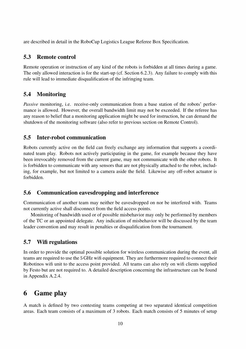
Sub-assembly Deployable Prerequisites ResultS0 T1, T2, T3, T4, T5 none S1, P3 or consumedS1 T2, T3, T4 S0 S2 or consumedS2 T3, T4 S0, S1 P1, P2
Late Order T5 none Processed Late Order
Table 6: The production table
a robot if it is not moving at all for more than 120 seconds and seemingly not waiting at a gamerelevant place, e.g. at a temporarily out-of-order machine, or if it may harm or damage the field orother robots.
If a robot needs to be taken out for the second time, either on request or as decided by thereferee, it is disqualified from the current game. It may no longer communicate with the still activerobots and must be taken out of the competition area.
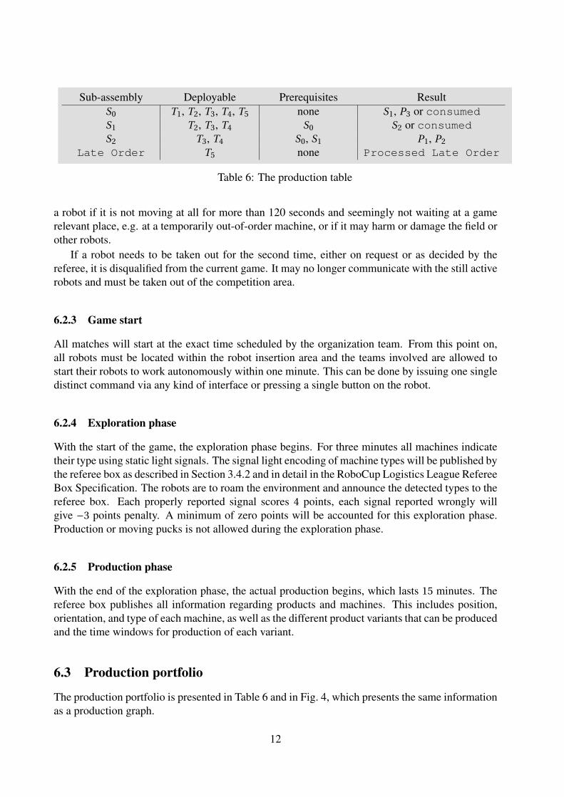
6.2.3 Game start
All matches will start at the exact time scheduled by the organization team. From this point on,all robots must be located within the robot insertion area and the teams involved are allowed tostart their robots to work autonomously within one minute. This can be done by issuing one singledistinct command via any kind of interface or pressing a single button on the robot.
6.2.4 Exploration phase
With the start of the game, the exploration phase begins. For three minutes all machines indicatetheir type using static light signals. The signal light encoding of machine types will be published bythe referee box as described in Section 3.4.2 and in detail in the RoboCup Logistics League RefereeBox Specification. The robots are to roam the environment and announce the detected types to thereferee box. Each properly reported signal scores 4 points, each signal reported wrongly willgive −3 points penalty. A minimum of zero points will be accounted for this exploration phase.Production or moving pucks is not allowed during the exploration phase.
6.2.5 Production phase
With the end of the exploration phase, the actual production begins, which lasts 15 minutes. Thereferee box publishes all information regarding products and machines. This includes position,orientation, and type of each machine, as well as the different product variants that can be producedand the time windows for production of each variant.
6.3 Production portfolio
The production portfolio is presented in Table 6 and in Fig. 4, which presents the same informationas a production graph.
12

P3T5S0
(a) P3
S1T1S0
(b) S1
S2T2
S0
S1
(c) S2
P1T3
S0
S1
S2
(d) P1
P2T4
S0
S1
S2
(e) P2
Figure 4: Production Chain Diagrams showing the machines and inputs relative to their outputs.
6.3.1 The production table
Table 6 shows the production table for the main challenge; the multistaged production processesas well as the Late Order Challenge. The main challenge can be repeated as long as enoughpallet carriers can be provided to complete the cycle. The different machine types are specified inSect. 3.4.
6.3.2 Late order
The late order challenge is derived from the former express good rule. It will be announced at arandom time by the referee box in form of an updated order information message listing a neworder for a P3 product to be delivered within a specified time window of 120 sec length. The orderwill be added to the periodically order information message as soon as the delivery time windowbegins. The challenge requires a fast paced processing and delivery of the requested product intime. There will be two late orders per game at randomized times.
The P3 product can be produced from any S0 puck at a T5 machine at any time (it may bepre-produced). In order to allow visually triggered processing an S0 will be placed in the late orderinsertion slot above the input storage as soon as a late order is announced. This S0 puck will notbe removed and can also be used for normal production. Note that, if the late order insertion slotalready contains an S0 when the next late order arrives an additional S0 puck is placed in the inputstorage.
A robot may not be initially placed next to the insertion slot, but only in the robot insertion area(below the input storage).
13
6.4 During a matchAny referee can interrupt the match at any time. After the referee box is stopped, all robots have 5seconds to stop all robot movement. Robots that do not stop within the time limit will be treatedin the same way as misbehaving robots (cf. Section 6.2.2). The match time will be paused duringthe interruption.
6.4.1 Out-of-order
The downtime generator will take down a maximum of two machines out of the pool containingproduction machines and recycling units. It will do so at random points of time. There will be 6 to8 of such triggered events during a match. The machines affected will remain out of order for 30 to120 seconds. Every machine can only be forced out of order once per match. If the machine turnsoffline during processing or consumption of mounted a pallet carrier, it will afterwards resume theprocess. The refbox will adjust the down times of T5 machines not to collide with late orders toallow production and delivery within the late order time.
6.4.2 Production Plan
The referee box will announce a production plan. It will consist of the products to produce, theamount thereof, and delivery time slots for each product. There will be three time slots for thegame, each lasting 5 minutes. Hence the first time slot will begin on game start and last until 4:59.The second slot starts at 5:00 and lasts until 9:59. The third time slots starts at 10:00 and lastsuntil 15:00. The later order is added to the production plan as soon as its delivery time slot starts(cf. Section 6.3.2).
Products which are delivered in the requested time slots score considerably higher than theones delivered outside of the time slots. The production plan is shown in Table 7. The numbersindicate how many products of a certain type shall be produced in each time slot. Each number isin the range from 1 to 10.
In the round-robin phase (cf. Section 7.1) each team will get the same production plan depend-ing on the game number, i.e. all teams will have the same plan in their first game, but the plan willbe a different one in the second game (but still the same for each team’s second game). In the play-off and final phases the production plan is the same for the two teams directly competing againsteach other but not for the other two competing teams. This is to avoid any potential influence onthe result of prior knowledge of the later playing teams.
7 Tournament
7.1 Tournament Scoring SpecificationsRound-Robin phase There will be three stages in the tournament. The first stage is a groupphase and will be played as a round-robin. The best 4 teams of the round-robin stage will advanceto a playoff round. The best 2 teams of this phase play the final game.
At the round-robin stage, the teams will receive the true points they scored by delivering andproducing goods during the competition. The points will be accumulated in this phase and theteams will be ranked according to the accumulated points in descending order.
14

Sub-task Main challenge PointsProduce S2 Finish the work order of a machine type 2 +4Produce productvariant P1
Finish the work order of a machine type 3 +12
Produce productvariant P2
Finish the work order of a machine type 4 +12
Produce productvariant P3
Finish the work order of a machine type 5 +0
Delivery Deliver one of the final product variants to the designated loadingzone at the time specified in the order
+10
Wrong delivery Deliver one of the final product variants to the designated loadingzone out of the requested time range or after all products requestedin the period have already been delivered
+1
False delivery Deliver an intermediate product 0Recycle Taking a consumed material from a machine that completed its
work cycle to the recycling machine+5
(a) Scoring scheme for the main challenge
Sub-task LOC - Late Order Challenge PointsDelivery of LO Deliver the processed late order (LO) to the active delivery gate in
time.+20
(b) Scoring scheme for the late order challenge
Reported Exploration Phase PointsCorrectly Correctly determine a machine type and report it successfully to
the refbox+4
Incorrectly Wrongly reported machine type -3Round Total A maximum of 40 points can be achieved by correctly reporting all
ten field machines. A minimum of 0 points is awarded.0 – 40
(c) Scoring scheme for the exploration phase
Table 8: Scoring Scheme
15

Slot Parameters Demanded number of items1 N1,1, N2,1, N3,1 N1,1 = Number of P1 to produce in slot 1
N2,1 = Number of P2 to produce in slot 1N3,1 = Number of P3 to produce in slot 1
2 N1,2, N2,2, N3,2 N1,2 = Number of P1 to produce in slot 2N2,2 = Number of P2 to produce in slot 2N3,2 = Number of P3 to produce in slot 2
3 N1,3, N2,3, N3,3 N1,3 = Number of P1 to produce in slot 3N2,3 = Number of P2 to produce in slot 3N3,3 = Number of P3 to produce in slot 3
Table 7: Production plan
Playoffs At the playoff stage, the scoring scheme will be different. As each team in this phasedirectly competes with an opposing team, the team that scores more points as the direct opponent,will be announced as the winner and 3 points will be awarded to this team. A loss will be awardedwith 0 points. Additionally, if both teams are unable to score any points during the match bydelivering or producing goods, both teams will receive 0 points. In case of a draw within theplayoffs, the game time will be extended by 5 minutes unless both teams scored zero points. Thiswill be announced by the refbox instead of a game closed message. If this extension leads to adraw too the overall regular points of the teams will determine the match winner. If the overallpoints are equal too, a direct comparison between the teams in question will decide. If this fails toresolve the situation, the teams will approach a coin toss to determine the winner.
Finals. The best 2 teams of the playoff phase will advance to the finals. The two teams competedirectly in concurrent games. The team that scores more points after the regular game time wins.If there is no winner after the regular time, the game continues for 5 more minutes. If after thistime there is still no winner, a coin toss will decide.
The detailed seeding will be created at the event. Although the idea is to allow each participantto challenge each other team the league can be adjusted to meet time requirements.
7.2 Task fulfillmentTable 8 provides the itemized clearance of all task related processes and their scoring.
7.3 PenaltiesThe catalog in Table 9 represents the decision basis for the referees without being exhaustive orbinding. The abidance of these rules will be monitored by at least two referees. One “field” refereewill overlook the competition area. The field referee is allowed to enter the area at any time.Accidental moving of a puck or similar unintended tampering resulting from the referees presenceon the field must be coped with. A second "station" referee operates the control station for thereferee box to issue the initial start command and monitor the game flow and the correctness of thedigital representation and automatic scoring.
16
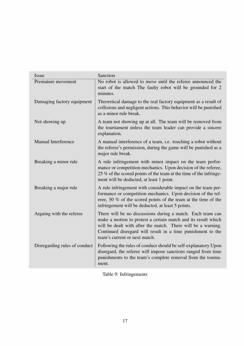
Issue SanctionPremature movement No robot is allowed to move until the referee announced the
start of the match The faulty robot will be grounded for 2minutes.
Damaging factory equipment Theoretical damage to the real factory equipment as a result ofcollisions and negligent actions. This behavior will be punishedas a minor rule break.
Not showing up A team not showing up at all. The team will be removed fromthe tournament unless the team leader can provide a sincereexplanation.
Manual Interference A manual interference of a team, i.e. touching a robot withoutthe referee’s permission, during the game will be punished as amajor rule break.
Breaking a minor rule A rule infringement with minor impact on the team perfor-mance or competition mechanics. Upon decision of the referee,25 % of the scored points of the team at the time of the infringe-ment will be deducted, at least 1 point.
Breaking a major rule A rule infringement with considerable impact on the team per-formance or competition mechanics. Upon decision of the ref-eree, 50 % of the scored points of the team at the time of theinfringement will be deducted, at least 5 points.
Arguing with the referee There will be no discussions during a match. Each team canmake a motion to protest a certain match and its result whichwill be dealt with after the match. There will be a warning.Continued disregard will result in a time punishment to theteam’s current or next match.
Disregarding rules of conduct Following the rules of conduct should be self-explanatory Upondisregard, the referee will impose sanctions ranged from timepunishments to the team’s complete removal from the tourna-ment.
Table 9: Infringements
17

7.4 Technical ChallengeWithin the league, the technical advances should be documented from year to year. Therefore, theTechnical Challenge is introduced. Each team should prepare for participating in any number ofthe following tasks. However, participation has no influence on the normal game results, but thewinner will be awarded by a certificate.
Navigation and collision avoidance. The single robot is to show that it avoids other obstaclesand robots while moving along specified points. Therefore the robot must drive from the inputstorage to the delivery zone within 60 seconds. However, the paths between the input storage andthe delivery zone will be blocked randomly by static obstacles and the robot must not touch anyof the obstacles. For touching an obstacle, the team receives a penalty. The fastest team with thefewest penalty points to reach the delivery zone wins this challenge. All other teams are rankedaccording to how fast they were and how many penalties they conceived. Initially, the robot will beplaced by a team leader of a different team anywhere in the input storage. The team has 15 secondsto perform a quick setup after the robot has been placed. The robot has completed the challengeas soon as it touches the delivery zone at any point. In 2013, the robotino transport cases will beused as static obstacles. The total number of obstacles will be the same for all teams. Possibledistributions of the obstacles will be defined by the team leaders before the challenge starts (e.g. 6possible distributions). A roll of dice will decide the actual distribution of obstacles.
Whack-a-Mole. A single robot is placed somewhere on the field. The team has 15 seconds toperform a quick setup after the robot has been placed. It then has to detect the single shining signalunit on the play field. The regarding unit will have all lights - green,yellow, and red - switchedon. As soon as the robot enters the related machine area of that signal, the signal unit has beenas whacked, is switched off and another random signal unit is switched on. A robot is inside amachine area if and only if it’s center is within the area. This is detected by the visual trackingsystem if available, or the human referee. Partaking robots must therefore be equipped with theappropriate markers. The goal of the challenge is to switch off as many signal units as possiblewithin a given time frame. Teams are ranked according to the number of turned-off signals.
Free challenge. Each team will be given 5 minutes to showcase their robot team, e.g. showsome new robotics developments. This may involve any task as long as it is performed with atmost three Robotino robots within the competition area. For the time of the free challenge, anysoftware or hardware modification is allowed, even though otherwise disallowed in the regularcompetition. This may be used to showcase ideas for future developments of the league and tohighlight particular advances in the system of the presenting team.
The team leaders of non-presenting team will judge the performance and rate it with pointsbetween 0–10. The team with the most sum of points will win this challenge. The other teams areranked in decreasing point order.
Conducting the Challenges. The technical challenges are conducted in the following way. Theteam leader of each participating team agree on a date and time during the tournament for theTechnical Challenge in their first Team leader Meeting. For each type of challenge, a time slot isassigned in which teams can participate once in the challenge. Each team can register for any of
18

the challenges. All team leaders have to be present at the time of the challenge to judge the otherteams. The OC is responsible to conduct the Technical Challenge and can appoint team leadersto support in conducting the challenges. Each challenge will have a separate ranking. In eachranking, the team on the last rank will receive 0 points, the last-but-one ranked team will receive1 point etc. The points for each ranking will be added and the team with the most points accruedover all challenges will be awarded with the Logistic Leagues Technical Challenge Award.
19
A Engineering Reference
A.1 The Mobile Robot System
The mobile robot system Robotino is a platform with an open mechanical interface for the integra-tion of additional mechanical devices and an open electrical interface to integrate easily additionalsensors or motors of devices. Power is supplied via two 12 V lead gel batteries which permit a run-ning time of up to two hours. The scope of delivery likewise includes a charging device. Robotinois driven by 3 independent, omni-directional drive units. They are mounted at an angle of 120° toeach other. The three omni-directional drive units of Robotino, defines the robot as being holo-nomic, meaning that the controllable degrees of freedom equals the total degrees of freedom of therobot. The drive units are integrated in a sturdy, laser welded steel chassis. The chassis is protectedby a rubber bumper with integrated switching sensor.
A.1.1 Robot Dimensions
Diameter: 370 mm
Height including housing: 210 mm
Overall weight: approx. 11 kg
Maximal payload: about 6 kg
A.1.2 Drive Unit
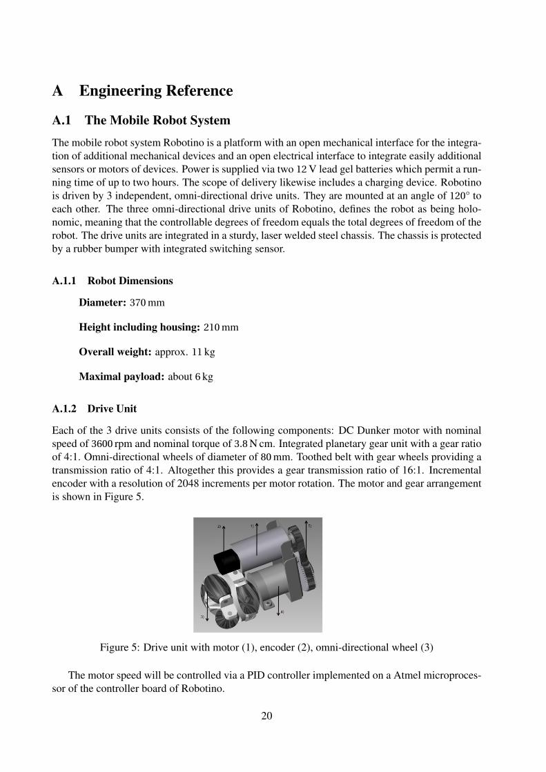
Each of the 3 drive units consists of the following components: DC Dunker motor with nominalspeed of 3600 rpm and nominal torque of 3.8 N cm. Integrated planetary gear unit with a gear ratioof 4:1. Omni-directional wheels of diameter of 80 mm. Toothed belt with gear wheels providing atransmission ratio of 4:1. Altogether this provides a gear transmission ratio of 16:1. Incrementalencoder with a resolution of 2048 increments per motor rotation. The motor and gear arrangementis shown in Figure 5.
Figure 5: Drive unit with motor (1), encoder (2), omni-directional wheel (3)
The motor speed will be controlled via a PID controller implemented on a Atmel microproces-sor of the controller board of Robotino.
20

A.1.3 Sensors
Robotino is equipped with 9 infrared distance measuring sensors which are mounted in the chassisat an angle of 40° to one another. Robotino can scrutinize all surrounding areas for objects withthese sensors. Each of the sensors can be queried individually via the controller board. Obstaclescan thus be avoided, clearances can be maintained and bearings can be taken on a selected target.The sensors are capable of accurate or relative distance measurements to objects at distances of4 cm to 30 cm. Sensor connection is especially simple including just one analogue output signaland supply power. The sensors’ evaluation electronics determines distance and read it out as ananalogue signal. The anti-collision sensor is comprised of a switching strip which is secured aroundthe entire circumference of the chassis. A reliably recognizable signal is thus transmitted to thecontroller unit. Collisions with objects at any point on the housing are detected and, for example,Robotino is brought to a standstill. The inductive proximity sensor is supplied as an additionalcomponent. It serves to detect metallic objects on the floor.
The inductive proximity sensor must be attached to the mounting furnished for this purpose,and must be connected to the I/O interface. The output voltage is 0 V to 10 V. The sensing rangeis 0 mm to 6 mm. Path tracking can also be implemented with the two included diffuse sensors.Flexible fiber optic cables are connected to a fiber-optics unit which works with visible red light.Reflected light is detected. Different surfaces and colors produce different degrees of reflection.However, gradual differences in reflected light cannot be detected. The sensors must be attachedto the mountings furnished for this purpose, and must be connected to the I/O interface.
Robotino is equipped with a color webcam. The webcam is equipped with a USB interface.Also, there will be integrated a digital Gyroscope providing a high accuracy of the odometry in thevirtual factory.
A.1.4 Controller Board – 2010 Revision
The controller housing is connected to the wiring in the chassis via one plug-in. Thus you caneasily take off the controller housing and you have direct access to the mechanical system. Thecontroller system of Robotino is divided into two parts – an embedded PC and a micro-controller
21

interface card: The Controller of Robotino consists of an embedded PC and a micro-controllerinterface board. The main controller is the embedded PC 104 plus controller with the 500 MHzprocessor AMD LX800. The PC has a SDRAM of 128 MB and is provided with a 1 GB flash card.There are numerous communication interfaces on board:
• 2 × 100 Mbit/s Ethernet
• 2 × external USB, 1 × on-board USB-connector
• 2 × RS232
• 1 × Parallel port and 1 × VGA port
• Wireless LAN Access Point following the standards 802.11/b/g.
• The access point can be switched into a client mode. As an option you may use WPA2-coding.
A.1.5 Software
Preinstalled is an Ubuntu Linux operating system with real time kernel running on the embeddedPC 104. The main part of the controller is the Robotino server, a real time Linux application.It controls the drive units and provides interfaces to communicate with external PC applicationsvia wifi. There is an API with libraries which allow you to create applications for Robotino innumerous programming languages:
• C++ and C
• C#
• .net and JAVA
• MatLab and Simulink
• Labview
You may find a lot of examples concerning using the different API’s in the public forum “Open-robotino” at http://www.openrobotino.org.
Robotino View Robotino View is a graphical programming language with numerous preparedfunction blocks you can easily connect via input and output parameters to establish more compli-cated function diagrams. You can use these function diagrams as subprograms for more complexprogramming sequences. To build up general programming sequences Robotino View follows theinternational standard IEC 61131-3. You may run Robotino View on an external PC and RobotinoView communicates directly with the Robotino Server on the PC 104 via wifi in order to controlthe robot system. The function blocks receive a direct feedback of the hardware components suchthat you can live interact with the robot system. On the other hand you can download RobotinoView programs into the PC 104 in order to run the applications completely autonomously. Thereis a well defined interface to develop own function blocks in C++ or Lua.
22
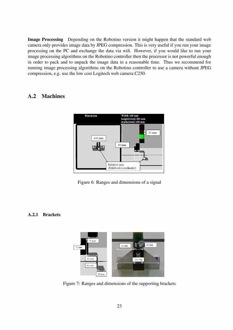
Image Processing Depending on the Robotino version it might happen that the standard webcamera only provides image data by JPEG compression. This is very useful if you run your imageprocessing on the PC and exchange the data via wifi. However, if you would like to run yourimage processing algorithms on the Robotino controller then the processor is not powerful enoughin order to pack and to unpack the image data in a reasonable time. Thus we recommend forrunning image processing algorithms on the Robotino controller to use a camera without JPEGcompression, e.g. use the low cost Logitech web camera C250.
A.2 Machines
Figure 6: Ranges and dimensions of a signal
A.2.1 Brackets
Figure 7: Ranges and dimensions of the supporting brackets
23

A.2.2 Signal
Dimension & diameter 36 mmheight(total) 147 mmSegment height 34 mm, including 5 mm unlighted borderLifespan max. 50.000 hConnector Bottom, 2 m supplied Compatible to the I/O-Terminal of MPS(r) units.Safety IP65Voltage 24 VCurrent 3 × 40 mAKind of current DCOperating mode −20 ◦C to 50 ◦CSignal type Static LEDSignal Ultra-bright LEDSource Festo # 549843
Table 10: Technical specification of the signal
A.2.3 RFID device
Technical data of the read/write head Housing rectangularHousing and working dimensions 40 mm×40 mm with the centered RFID tag.Housing height 65 mmOperating voltage DCHousing material Plastic PBT-GF30-V0, blackMaterial active face Plastic PA6-GF30, yellowOperating voltage 10 V DC to 30 V DCDC rated operational current ≤ 80 mAData transfer inductance couplingWorking frequency 13.56 MHzRadio communication and protocol standards ISO 15693Read/write distance max. 115 mmOutput function 4-wire, read/writeElectrical connection Connectors M12 × 1Vibration resistance 55 Hz (1 mm)Shock resistance 30 g (11 ms)Protection class IP67Operating voltage display LED green
Table 11: Technical specification of the RFID device
24

A.2.4 Wifi equipment
Festo AP LANCOM L-322agnTransfer rate Up to 108 Mbit s−1
Data link protocol 802.11 a/g/nFrequency 5.0 GHzIP-distribution 172.26.200.xxx for LAN clients(DHCP)
172.26.101.xxx for the Robotino devices172.26.1.xxx for Robotinos
Subnet Mask 255.255.0.0Encryption UnsecuredSSID Separated for both teams:
RobotinoEvent.1RobotinoEvent.2
Festo Clients 3COM WL-560Power Supply Clients: 12 V, 1 A,
Most Laptops cannot power themvia USB!
Connector Ethernet
Table 12: Technical specification of the wifi equipment
A.2.5 Data carrier
Dimension �20 mmHeight 2.5 mmData transfer inductance couplingWorking frequency 13.56 MHzMemory read/writeMemory type EEPROMMemory size 128 BFreely usable memory 112 BNumber of read operations unlimitedNumber of write operations 105Typical read time 2 ms B−1
Typical write time 3 ms B−1
Radio communication and protocol standards ISO 15693
Table 13: Technical specification of the data carrier
25