RN131/171 Evaluation Kit User's Guide - Microchip...
46
2013 Microchip Technology Inc. DS50002183A RN131/171 Evaluation Kit User’s Guide
Transcript of RN131/171 Evaluation Kit User's Guide - Microchip...

2013 Microchip Technology Inc. DS50002183A
RN131/171 Evaluation KitUser’s Guide
DS50002183A-page 2 2013 Microchip Technology Inc.
Information contained in this publication regarding deviceapplications and the like is provided only for your convenienceand may be superseded by updates. It is your responsibility toensure that your application meets with your specifications.MICROCHIP MAKES NO REPRESENTATIONS ORWARRANTIES OF ANY KIND WHETHER EXPRESS ORIMPLIED, WRITTEN OR ORAL, STATUTORY OROTHERWISE, RELATED TO THE INFORMATION,INCLUDING BUT NOT LIMITED TO ITS CONDITION,QUALITY, PERFORMANCE, MERCHANTABILITY ORFITNESS FOR PURPOSE. Microchip disclaims all liabilityarising from this information and its use. Use of Microchipdevices in life support and/or safety applications is entirely atthe buyer’s risk, and the buyer agrees to defend, indemnify andhold harmless Microchip from any and all damages, claims,suits, or expenses resulting from such use. No licenses areconveyed, implicitly or otherwise, under any Microchipintellectual property rights.
Note the following details of the code protection feature on Microchip devices:
• Microchip products meet the specification contained in their particular Microchip Data Sheet.
• Microchip believes that its family of products is one of the most secure families of its kind on the market today, when used in the intended manner and under normal conditions.
• There are dishonest and possibly illegal methods used to breach the code protection feature. All of these methods, to our knowledge, require using the Microchip products in a manner outside the operating specifications contained in Microchip’s Data Sheets. Most likely, the person doing so is engaged in theft of intellectual property.
• Microchip is willing to work with the customer who is concerned about the integrity of their code.
• Neither Microchip nor any other semiconductor manufacturer can guarantee the security of their code. Code protection does not mean that we are guaranteeing the product as “unbreakable.”
Code protection is constantly evolving. We at Microchip are committed to continuously improving the code protection features of ourproducts. Attempts to break Microchip’s code protection feature may be a violation of the Digital Millennium Copyright Act. If such actsallow unauthorized access to your software or other copyrighted work, you may have a right to sue for relief under that Act.
Microchip received ISO/TS-16949:2009 certification for its worldwide headquarters, design and wafer fabrication facilities in Chandler and Tempe, Arizona; Gresham, Oregon and design centers in California and India. The Company’s quality system processes and procedures are for its PIC® MCUs and dsPIC® DSCs, KEELOQ® code hopping devices, Serial EEPROMs, microperipherals, nonvolatile memory and analog products. In addition, Microchip’s quality system for the design and manufacture of development systems is ISO 9001:2000 certified.
QUALITY MANAGEMENT SYSTEM CERTIFIED BY DNV
== ISO/TS 16949 ==
Trademarks
The Microchip name and logo, the Microchip logo, dsPIC, FlashFlex, KEELOQ, KEELOQ logo, MPLAB, PIC, PICmicro, PICSTART, PIC32 logo, rfPIC, SST, SST Logo, SuperFlash and UNI/O are registered trademarks of Microchip Technology Incorporated in the U.S.A. and other countries.
FilterLab, Hampshire, HI-TECH C, Linear Active Thermistor, MTP, SEEVAL and The Embedded Control Solutions Company are registered trademarks of Microchip Technology Incorporated in the U.S.A.
Silicon Storage Technology is a registered trademark of Microchip Technology Inc. in other countries.
Analog-for-the-Digital Age, Application Maestro, BodyCom, chipKIT, chipKIT logo, CodeGuard, dsPICDEM, dsPICDEM.net, dsPICworks, dsSPEAK, ECAN, ECONOMONITOR, FanSense, HI-TIDE, In-Circuit Serial Programming, ICSP, Mindi, MiWi, MPASM, MPF, MPLAB Certified logo, MPLIB, MPLINK, mTouch, Omniscient Code Generation, PICC, PICC-18, PICDEM, PICDEM.net, PICkit, PICtail, REAL ICE, rfLAB, Select Mode, SQI, Serial Quad I/O, Total Endurance, TSHARC, UniWinDriver, WiperLock, ZENA and Z-Scale are trademarks of Microchip Technology Incorporated in the U.S.A. and other countries.
SQTP is a service mark of Microchip Technology Incorporated in the U.S.A.
GestIC and ULPP are registered trademarks of Microchip Technology Germany II GmbH & Co. & KG, a subsidiary of Microchip Technology Inc., in other countries.
All other trademarks mentioned herein are property of their respective companies.
© 2013, Microchip Technology Incorporated, Printed in the U.S.A., All Rights Reserved.
Printed on recycled paper.
ISBN: 978-1-62077-365-9

RN131/171 Evaluation Kit User’s Guide
Object of Declaration: RN131/171 Evaluation Kit
2013 Microchip Technology Inc. DS50002183A-page 3

RN131/171 Evaluation Kit User’s Guide
NOTES:
2013 Microchip Technology Inc. DS50002183A-page 4

RN131/171 EVALUATION KIT
USER’S GUIDE
Table of Contents
Preface ........................................................................................................................... 7
Chapter 1. Overview1.1 Introduction ................................................................................................... 131.2 RN131/171 Evaluation Kit Features ............................................................. 131.3 RN131/171 Evaluation Kit Contents and Part Details .................................. 141.4 RN131 and RN171 Evaluation Kits Content ................................................. 151.5 RN131/171 Evaluation Related Contents ..................................................... 18
Chapter 2. Getting Started2.1 Introduction ................................................................................................... 192.2 Hardware Requirements .............................................................................. 192.3 Software/Utility Requirements ...................................................................... 202.4 Module Configuration ................................................................................... 21
Chapter 3. Application Design Concerns3.1 Introduction ................................................................................................... 29
Appendix A. RN131 and RN171 Evaluation Kits SchematicA.1 Introduction .................................................................................................. 31A.2 RN131 and RN171 Evaluation Kits Schematic ............................................ 31A.3 RN131 and RN171 Evaluation Kits PCB Layout and Assembly Drawings .. 34A.4 RN131 and RN171 Evaluation Kits Bill of Materials .................................... 40A.5 RN131 and RN171 Evaluation Kits Physical Dimensions ............................ 42
Index ............................................................................................................................. 45
Worldwide Sales and Service .................................................................................... 46
2013 Microchip Technology Inc. DS50002183A-page 5

RN131/171 Evaluation Kit User’s Guide
NOTES:
DS50002183A-page 6 2013 Microchip Technology Inc.

RN131/171 EVALUATION KITUSER’S GUIDE
Preface
INTRODUCTIONThis chapter contains general information that will be useful to know before using the RN131/171 Evaluation Board User’s Guide. Items discussed in this chapter include:
• Document Layout
• Conventions Used in this Guide
• Warranty Registration
• Recommended Reading
• The Microchip Web Site
• Development Systems Customer Change Notification Service
• Customer Support
• Document Revision History
DOCUMENT LAYOUTThis document describes how to use the RN131/171 Evaluation Board. The manual layout is as follows:
• Chapter 1. “Overview” – This chapter describes the RN131 and RN171 Evalua-tion Kits that are used for demonstrating the RN131 and RN171 module capabilities. These boards have the flexibility to connect directly to computers/laptops through a standard USB interface or to an embedded controllers through the serial UART interface.
• Chapter 2. “Getting Started” – This chapter describes the RN131 and RN171 Evaluation Kits as an independent development board to add Wi-Fi® connectivity to embedded systems. Certain hardware and software/utilities are essential to support the development of demo applications which are also discussed in this chapter.
NOTICE TO CUSTOMERS
All documentation becomes dated, and this manual is no exception. Microchip tools and documentation are constantly evolving to meet customer needs, so some actual dialogs and/or tool descriptions may differ from those in this document. Please refer to our web site (www.microchip.com) to obtain the latest documentation available.
Documents are identified with a “DS” number. This number is located on the bottom of each page, in front of the page number. The numbering convention for the DS number is “DSXXXXXA”, where “XXXXX” is the document number and “A” is the revision level of the document.
For the most up-to-date information on development tools, see the MPLAB® IDE online help. Select the Help menu, and then Topics to open a list of available online help files.
2013 Microchip Technology Inc. DS50002183A-page 7

RN131/171 Evaluation Kit User’s Guide
• Chapter 3. “Application Design Concerns” – This chapter provides design con-cerns related to powering the evaluation board, sensor interface settings, Ad hoc mode, and restoring factory settings.
• Appendix A. “RN131 and RN171 Evaluation Kits Schematic” – This appendix provides the RN131 and RN171 Evaluation Boards schematic, PCB layout and Bill of Materials (BOM).
CONVENTIONS USED IN THIS GUIDE
This manual uses the following documentation conventions:
DOCUMENTATION CONVENTIONS
Description Represents Examples
Arial font:
Italic characters Referenced books MPLAB® IDE User’s Guide
Emphasized text ...is the only compiler...
Initial caps A window the Output window
A dialog the Settings dialog
A menu selection select Enable Programmer
Quotes A field name in a window or dialog
“Save project before build”
Underlined, italic text with right angle bracket
A menu path File>Save
Bold characters A dialog button Click OK
A tab Click the Power tab
Text in angle brackets < > A key on the keyboard Press <Enter>, <F1>
Courier New font:
Plain Courier New Sample source code #define START
Filenames autoexec.bat
File paths c:\mcc18\h
Keywords _asm, _endasm, static
Command-line options -Opa+, -Opa-
Bit values 0, 1
Constants 0xFF, ‘A’
Italic Courier New A variable argument file.o, where file can be any valid filename
Square brackets [ ] Optional arguments mcc18 [options] file [options]
Curly brackets and pipe character: { | }
Choice of mutually exclusive arguments; an OR selection
errorlevel {0|1}
Ellipses... Replaces repeated text var_name [, var_name...]
Represents code supplied by user
void main (void){ ...}
DS50002183A-page 8 2013 Microchip Technology Inc.

Preface
WARRANTY REGISTRATION
Please complete the enclosed Warranty Registration Card and mail it promptly. Sending in the Warranty Registration Card entitles you to receive new product updates. Interim software releases are available at the Microchip web site.
RECOMMENDED READING
This user’s guide describes how to use the RN-131-EK and RN-171-EK Evaluation Boards. Other useful documents are listed below. The following Microchip documents are available and recommended as supplemental reference resources.
RN131 Module Data Sheet (DS75085)
RN171 Module Data Sheet (DS75084)
PICDEM™ PIC18 Explorer Demonstration Board User’s Guide (DS51721)
Explorer 16 Development Board User’s Guide (DS51589)
WiFly Command Reference, Advanced Features and Applications User’s Guide
2013 Microchip Technology Inc. DS50002183A-page 9

RN131/171 Evaluation Kit User’s Guide
THE MICROCHIP WEB SITE
Microchip provides online support through our web site at http://www.microchip.com. This web site is used as a means to make files and information easily available to customers. Accessible by using your favorite Internet browser, the web site contains the following information:
• Product Support – Data sheets and errata, application notes and sample programs, design resources, user’s guides and hardware support documents, latest software releases and archived software
• General Technical Support – Frequently Asked Questions (FAQs), technical support requests, online discussion groups, Microchip consultant program member listing
• Business of Microchip – Product selector and ordering guides, latest Microchip press releases, listing of seminars and events, listings of Microchip sales offices, distributors and factory representatives
DEVELOPMENT SYSTEMS CUSTOMER CHANGE NOTIFICATION SERVICE
Microchip’s customer notification service helps keep customers current on Microchip products. Subscribers will receive e-mail notification whenever there are changes, updates, revisions or errata related to a specified product family or development tool of interest.
To register, access the Microchip web site at http://www.microchip.com, click Customer Change Notification and follow the registration instructions.
The Development Systems product group categories are:
• Compilers – The latest information on Microchip C compilers and other language tools. These include the MPLAB® C compiler; MPASM™ and MPLAB 16-bit assemblers; MPLINK™ and MPLAB 16-bit object linkers; and MPLIB™ and MPLAB 16-bit object librarians.
• Emulators – The latest information on the Microchip MPLAB REAL ICE™ in-cir-cuit emulator.
• In-Circuit Debuggers – The latest information on the Microchip in-circuit debug-ger, MPLAB ICD 3.
• MPLAB® IDE – The latest information on Microchip MPLAB IDE, the Windows® Integrated Development Environment for development systems tools. This list is focused on the MPLAB IDE, MPLAB SIM simulator, MPLAB IDE Project Manager and general editing and debugging features.
• Programmers – The latest information on Microchip programmers. These include the MPLAB PM3 device programmers and the PICkit™ 3 development programmers.
CUSTOMER SUPPORT
Users of Microchip products can receive assistance through several channels:
• Distributor or Representative
• Local Sales Office
• Field Application Engineer (FAE)
• Technical Support
Customers should contact their distributor, representative or FAE for support. Local sales offices are also available to help customers. A listing of sales offices and locations is included in the back of this document.
Technical support is available through our web site at: http://support.microchip.com
DS50002183A-page 10 2013 Microchip Technology Inc.

Preface
DOCUMENT REVISION HISTORY
Revision A (August 2013)
This is the initial released version of the document.
2013 Microchip Technology Inc. DS50002183A-page 11

RN131/171 Evaluation Kit User’s Guide
NOTES:
DS50002183A-page 12 2013 Microchip Technology Inc.

RN131/171 EVALUATION KITUSER’S GUIDE
Chapter 1. Overview
1.1 INTRODUCTION
This chapter describes the RN131/171 Evaluation Kits that are used for demonstrating the RN131 and RN171 module capabilities. These boards have the flexibility to connect directly to computers/laptops through a standard USB interface or to embedded controllers through the serial UART interface. These evaluation boards contain two push buttons, namely RESET and FN. The RESET button is used to reset the module and the FN button is used to launch different applications depending on software configuration. The status LEDs enables quick debug support.
The RN171 Evaluation Board has an additional flexibility of powering up through battery pack (two AAA batteries) apart from connecting through USB cable to the host PC. Analog sensor interface supported by RN131 and RN171 Evaluation Boards also provides direct connections to read analog signals such as temperature, acceleration and so on.
For data sheet and other details related to RN131 and RN171 modules refer to the Microchip web site http://www.microchip.com.
This chapter discusses the following topics:
• RN131/171 Evaluation Kit Features
• RN131/171 Evaluation Kit Contents and Part Details
• RN131 and RN171 Evaluation Kits Content
• RN131/171 Evaluation Related Contents
1.2 RN131/171 EVALUATION KIT FEATURES
1.2.1 RN131 Evaluation Board Features
The RN131 Evaluation Board has the following features:
• Supports FCC/CE/IC certified 2.4 GHz IEEE 802.11 b/g RN131 module
• Wi-Fi® Alliance certified for WPA2-PSK and RoHS compliant
• Complete on-board TCP/IP networking stack through RN131 module
• Supports Ad hoc and Infrastructure networking modes along with SoftAP mode
• Built-in networking applications through RN131 module, such as, TCP/IP, DHCP, DNS, ARP, ICMP, UDP, Telnet, FTP client and HTML client
• Configuration over Wi-Fi or UART using simple ASCII commands
• Supports 921 Kbps TX, 500 Kbps RX data rates with TCP/IP and WPA2 over UART
• Powered by a USB cable (5V)
• Push buttons for launching Applications and RESET signals
• Real-time clock for wake up and time stamping
• The RN131 module includes an on-board ceramic chip antenna and a U.FL. con-nector
• Size – 50.8 mm x 28 mm x 5 mm
• Weight – approx. 10g
2013 Microchip Technology Inc. DS50002183A-page 13

RN131/171 Evaluation Kit User’s Guide
1.2.2 RN171 Evaluation Board Features
The RN171 Evaluation Board has the following features:
• Supports FCC/CE/IC certified 2.4 GHz IEEE 802.11 b/g RN171 module
• Wi-Fi Alliance certified for WPA2-PSK and RoHS compliant
• Complete on-board TCP/IP networking stack through RN171 module
• Supports Ad hoc and Infrastructure networking modes along with SoftAP mode
• Built-in networking applications through RN171 module, such as, TCP/IP, DHCP, DNS, ARP, ICMP, UDP, Telnet, FTP client and HTML client
• Configuration over Wi-Fi or UART using simple ASCII commands
• Supports 921 Kbps TX, 500 Kbps RX data rates with TCP/IP and WPA2 over UART
• Powered by 3.3V battery pack (two AAA batteries) or through a USB cable (5V)
• Push buttons for launching Applications and RESET signal
• 10 general purpose digital I/O pins
• Eight analog sensor interfaces; configurable sensor power outputs 0 – 3.3V DC
• Real-time clock for wake-up and time stamping
• Trace antenna included on the RN171 module
• Size – 50.8 mm x 28 mm x 20 mm
• Weight – approx. 13.5g
1.3 RN131/171 EVALUATION KIT CONTENTS AND PART DETAILS
Depending on the development kit ordered, the package contents contain one of the following development boards:
• RN-131-EK or EN-171-EK Board
• USB cable
Table 1-1 lists the part number of RN-131/171-EK Evaluation Kit.
TABLE 1-1: RN-131/171-EK EVALUATION KIT
Figure 1-1 illustrates the evaluation kit contents of RN-131-EK and RN-171-EK, respectively.
Description Part Number
RN131 Evaluation Kit RN-131-EK
RN171 Evaluation Kit RN-171-EK
DS50002183A-page 14 2013 Microchip Technology Inc.
Overview
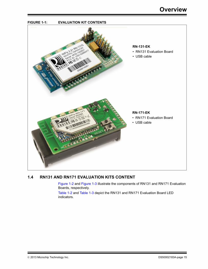
FIGURE 1-1: EVALUATION KIT CONTENTS
1.4 RN131 AND RN171 EVALUATION KITS CONTENT
Figure 1-2 and Figure 1-3 illustrate the components of RN131 and RN171 Evaluation Boards, respectively.
Table 1-2 and Table 1-3 depict the RN131 and RN171 Evaluation Board LED indicators.
RN-131-EK
• RN131 Evaluation Board
• USB cable
RN-171-EK
• RN171 Evaluation Board
• USB cable
2013 Microchip Technology Inc. DS50002183A-page 15

RN131/171 Evaluation Kit User’s Guide
FIGURE 1-2: RN131 EVALUATION BOARD COMPONENTS
TABLE 1-2: RN131 EVALUATION BOARD LED INDICATORS
Condition Blue LED Red LED Yellow LED Green LED
On Solid Not Used — — Connected over TCP
Fast Blink Not Used Not Associated RX/TX Data Transfer No IP address
Slow Blink Not Used Associated, no internet — IP address OK
Off Not Used Associated, internet OK — —
DS50002183A-page 16 2013 Microchip Technology Inc.

Overview
FIGURE 1-3: RN171 EVALUATION BOARD COMPONENTS
TABLE 1-3: RN171 EVALUATION BOARD LED INDICATORS
Condition Blue LED Red LED Yellow LED Green LED
On Solid Not Used — — Connected over TCP
Fast Blink Not Used Not Associated RX/TX Data Transfer No IP address
Slow Blink Not Used Associated, no internet — IP address OK
Off Not Used Associated, internet OK — —
Note 1: The RN171 module drives GPIO8 HIGH on power-up, which overrides software configured power-up values, such as set sys value 0x0000 on GPIO8.
2013 Microchip Technology Inc. DS50002183A-page 17
RN131/171 Evaluation Kit User’s Guide
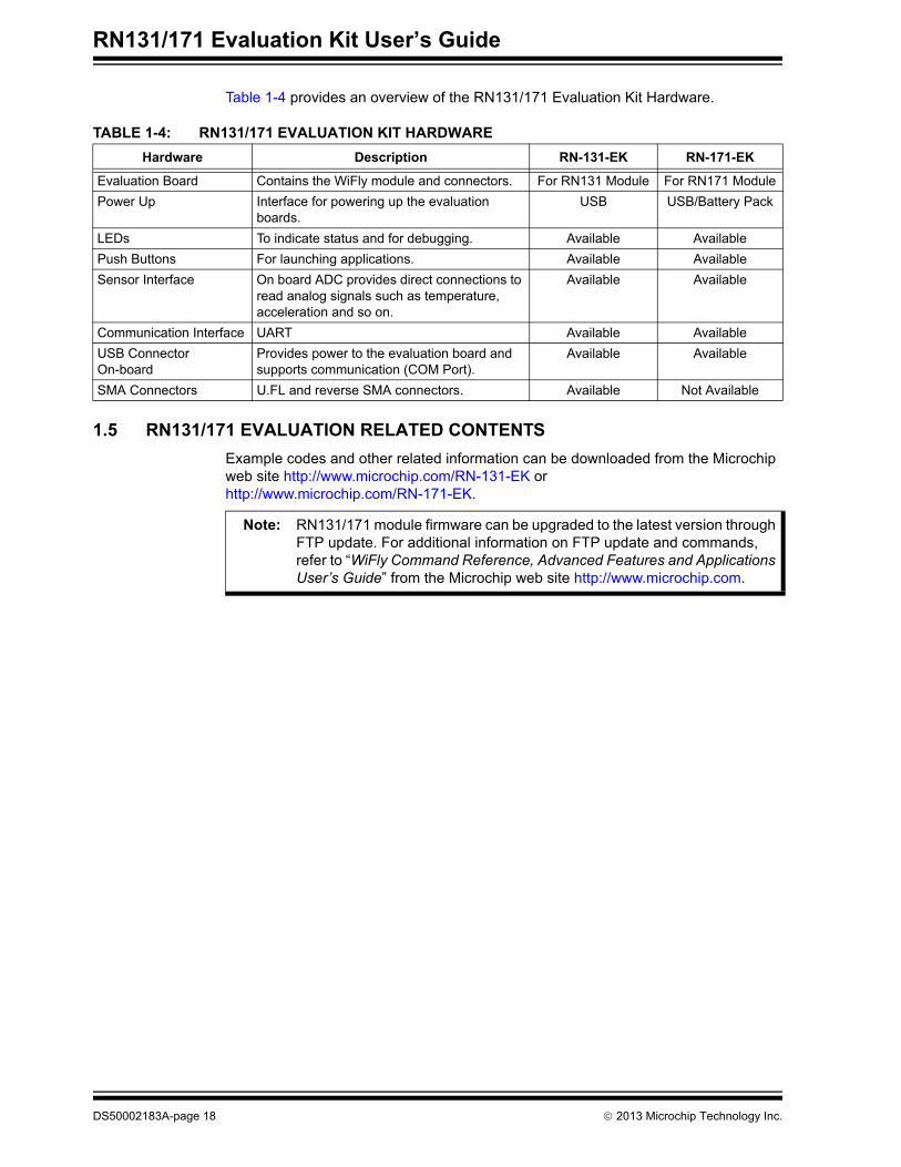
Table 1-4 provides an overview of the RN131/171 Evaluation Kit Hardware.
TABLE 1-4: RN131/171 EVALUATION KIT HARDWARE
1.5 RN131/171 EVALUATION RELATED CONTENTS
Example codes and other related information can be downloaded from the Microchip web site http://www.microchip.com/RN-131-EK or http://www.microchip.com/RN-171-EK.
Hardware Description RN-131-EK RN-171-EK
Evaluation Board Contains the WiFly module and connectors. For RN131 Module For RN171 Module
Power Up Interface for powering up the evaluation boards.
USB USB/Battery Pack
LEDs To indicate status and for debugging. Available Available
Push Buttons For launching applications. Available Available
Sensor Interface On board ADC provides direct connections to read analog signals such as temperature, acceleration and so on.
Available Available
Communication Interface UART Available Available
USB Connector On-board
Provides power to the evaluation board and supports communication (COM Port).
Available Available
SMA Connectors U.FL and reverse SMA connectors. Available Not Available
Note: RN131/171 module firmware can be upgraded to the latest version through FTP update. For additional information on FTP update and commands, refer to “WiFly Command Reference, Advanced Features and Applications User’s Guide” from the Microchip web site http://www.microchip.com.
DS50002183A-page 18 2013 Microchip Technology Inc.

RN131/171 EVALUATION KITUSER’S GUIDE
Chapter 2. Getting Started
2.1 INTRODUCTION
This chapter describes the RN131/171 Evaluation Kit board as an independent development board for exploring the ASCII command set and prototyping of embedded systems. Certain hardware and software/utilities are essential to support the development of demo applications.
This chapter discusses the following topics:
• Hardware Requirements
• Software/Utility Requirements
• Module Configuration
2.2 HARDWARE REQUIREMENTS
Along with an USB cable either RN-131-EK or RN-171-EK boards are required for eval-uation hardware setup and to run the demo applications.
2.2.1 Hardware Setup
The following are the steps to setup the RN131/171 Evaluation Board demo:
1. Supply power to RN-131-EK and RN-171-EK evaluation board using an USB cable. Alternatively, power can be supplied to RN-171-EK evaluation board by inserting two AAA batteries into the battery pack.
2. Connect the USB cable to a USB port on the host system and to the USB connector on the evaluation board.
3. If the drivers are not automatically installed, download and install the FTDI drivers from the Microchip web site “http://ww1.microchip.com/downloads/en/Device-Doc/FTDI-Drivers.zip” FTDI Chipset Drivers.
4. Once the FTDI drivers are installed, the COM port is automatically assigned based on the active connection.
Figure 2-1 and Figure 2-2 show the setup arrangement of RN131 and RN171 Evalua-tion Boards connected to computer/laptop.
2013 Microchip Technology Inc. DS50002183A-page 19

RN131/171 Evaluation Kit User’s Guide
FIGURE 2-1: RN131 EVALUATION BOARD HARDWARE SETUP
FIGURE 2-2: RN171 EVALUATION BOARD HARDWARE SETUP
2.3 SOFTWARE/UTILITY REQUIREMENTS
The following software tools/utilities are required to run the demo applications:
• Terminal Emulator Application such as TeraTerm (for Windows OS) or CoolTerm (for MAC OS)
• Both RN131 and RN171 Evaluation Boards use the FTDI chip set. Windows automati-cally installs the drivers for the USB-serial cable. If the drivers are not automatically installed, download and install the FTDI drivers from the Microchip web site “http://ww1.microchip.com/downloads/en/DeviceDoc/FTDI-Drivers.zip” FTDI Chipset Drivers.
Note: Terminal Emulator program is used to send the configuration commands to the module over a UART interface. The emulator also displays information transmitted from the module.
DS50002183A-page 20 2013 Microchip Technology Inc.

Getting Started
• Once the FTDI drivers are installed, the COM port is automatically assigned based on the active connection.
2.4 MODULE CONFIGURATION
The RN131/171 module operates in two modes:
• Data mode (default)
• Command mode
2.4.1 Data Mode
In Data mode, the RN131/171 module is essentially a data pipe. When the module receives data over Wi-Fi, it strips the TCP/IP headers and trailers, and passes the user data to the UART. When data is written to the UART, the module constructs the TCP/IP packet and sends it out over Wi-Fi. Thus, the entire process of sending/receiving data to the host is transparent to the end application/user microcontroller.
FIGURE 2-3: APPLICATION INTERFACE FOR DATA AND COMMAND MODES
2.4.2 Command Mode
By default, the RN131/171 module is in Data mode. Sending an escape sequence $$$ causes the module to enter the Command mode. Once in Command mode, module can be configured using simple ASCII commands. To exit Command mode and return to the Data mode, type exit <cr>. Figure 2-3 shows an application interface for Data and Command modes.
Basic configuration requires the wireless network access point’s name (SSID) and the authentication password. The RN131/171 module can associate with only one network at a time. It is recommended to begin evaluation by configuring the RN131/171 module using an open access point to simplify the setup.
The following two methods are used to configure the RN131/171 module:
1. Over the UART, that is connected to a computer/laptop or to a microcontroller
2. Through Wi-Fi using Ad hoc networking
Terminal emulator is required to type the commands and to monitor the transactions.
2013 Microchip Technology Inc. DS50002183A-page 21

RN131/171 Evaluation Kit User’s Guide
2.4.3 Configuration Using a USB Cable
The evaluation board uses a USB cable to allow the host computer to communicate with the RN131/171 module on the evaluation board.
The following instructions describe how to use a terminal emulator to go into Configura-tion mode, send commands to find networks, associate with an access point and save configuration.
2.4.3.1 CONFIGURE THE MODULE USING A TERMINAL EMULATOR
Either the TeraTerm (for Windows OS) or CoolTerm (for Mac OS-X), terminal emulator program can be used. Also legacy evaluation boards uses a USB-to-serial cable for connecting the evaluation board with the computer/laptop. When using either of the RN131/171 evaluation board, use the COM port to which the USB-to-serial cable is connected.
The following are the steps to communicate with the module using a terminal emulator:
1. Determine the COM port that is assigned to the USB cable (the port is COM9 in the example shown in Figure 2-4).
2. Open the available terminal emulation program and specify the COM port.
3. When using TeraTerm, go to Serial option and select the COM port number from the drop-down menu.
4. The serial port with the required settings are as follows:
- Baud: 9600
- Data bits: 8
- Parity: None
- Stop bits: 1
- Flow control: None
5. Type the commands through the terminal emulator program and to the assigned program.
Note: COM port number can be found as follows:
- For Windows OS: Go to the Windows Device Manager, from System Tools. In the Device Manager, browse and expand the selection for serial ports (COM & LPT). Use TeraTerm for other configuration settings and monitoring.
- For MAC OS: When using CoolTerm, view and select the port from the same terminal emulator application.
DS50002183A-page 22 2013 Microchip Technology Inc.

Getting Started
FIGURE 2-4: FINDING THE COM PORT NUMBER IN WINDOWS
2.4.3.2 ENTER COMMAND MODE
The following are the steps to enter the Command mode in a terminal emulator:
1. Type $$$ on the keyboard sequentially with no additional characters before or after each $ sign. The module replies with CMD (on terminal emulator) to indicate it is in Command mode.
2. Type show net <cr> to display the current network settings (Figure 2-5 shows the current network settings for the version 2.28).
FIGURE 2-5: CURRENT NETWORK SETTINGS
Note: When a command is completed, the terminal displays a prompt in the for-mat <X.XX>, where X.XX indicates the module’s firmware version.
2013 Microchip Technology Inc. DS50002183A-page 23

RN131/171 Evaluation Kit User’s Guide
Commands to the module is first sent with a keyword followed by an optional parame-ter. Spaces are not allowed to use as parameters. The commands are case sensitive. Use a $ to indicate a space (For example, MY NETWORK must be written as MY$NET-WORK). Additionally, short form for the parameters can be used. For example, the following commands are equivalent:
The RN131/171 module supports a variety of command keywords. The WiFly Com-mand Reference, Advanced Features and Applications User’s Guide Reference from the Microchip web site http://www.microchip.com provides a complete command of references.
For evaluation purposes, view the current settings using the get command; get everything to shows all parameters. Table 2-1 shows an additional parameters that can be used with set and get commands.
TABLE 2-1: BASIC SET AND GET PARAMETERS
2.4.3.3 FIND AVAILABLE NETWORKS
In Command mode, instruct the RN131/171 module to search for the available networks. By typing scan <cr> in the terminal emulator a list of Wi-Fi networks within the radio range can be viewed. Figure 2-6 shows the scanned network/access points.
set uart baudrate 115200
set uart b 115200
set u b 15200
Note: Short forms are not used for command keywords. For example, s uart baudrate 115200 is illegal.
Parameter Function
adhoc Controls the Ad hoc parameters
broadcast Controls the broadcast hello/heartbeat UDP message
comm Communication and data transfer, matching characters
dns DNS host and domain
ftp FTP host address and login information
ip IP settings
option Optional and infrequently used parameters
sys System settings (e.g., sleep and wake timers)
time Rea-time clock settings
uart Serial port settings (e.g., baud rate and parity)
wlan Wireless interface (e.g., SSID, channel and security options)
DS50002183A-page 24 2013 Microchip Technology Inc.

Getting Started
FIGURE 2-6: AVAILABLE NETWORKS THROUGH SCAN COMMAND
2.4.3.4 ASSOCIATE WITH AN ACCESS POINT
Use the join keyword to associate with an open access point. Figure 2-6 shows roving1 as an open access point in the scan list.
To associate with an access point, type the following commands:
To disconnect from a network, type leave <cr>. The Red LED blinks quickly when the RN131/171 module is not associated with an access point.
To associate a module automatically with a network upon booting (i.e., persistent con-figuration), use the set wlan command with the SSID. For example, type the following commands:
When the module wakes or power cycles, the module attempts to associate with the network roving1. To associate with a secure network, the module requires the net-work password. The WiFly RN131/171 module determines the security type automati-cally. In this case, type the following commands:
Figure 2-7 shows the secured network connection. To confirm this established connection and security settings type get wlan <cr>.
join roving1
or
join # 1
set wlan ssid roving1
save
reboot
set wlan ssid roving1
set wlan pass rubygirl
set wlan join 1 //enables auto join
save
reboot
2013 Microchip Technology Inc. DS50002183A-page 25

RN131/171 Evaluation Kit User’s Guide
FIGURE 2-7: CONNECT TO A SECURE NETWORK
2.4.4 Configuration Using AP Mode
AP mode released as part of the standard firmware replaces Ad hoc mode.
AP mode provides several advantages over Ad hoc mode.
In AP mode:
• The module creates a soft AP network to which Android devices (smartphones and tablets) can join. (Android devices do not support ad hoc networking.)
• The module runs a DHCP server and issues IP addresses to seven clients, which is much faster than automatic IP in Ad hoc mode.
• The RN131/171 module supports security, unlike Ad hoc, which is an open mode.
• The module supports routing between clients.
Load the appropriate firmware, version 2.45 or later, to enable the AP mode. Modify the boot image to version 2.45 to use AP mode. Change the module’s firmware image using the boot image <value> command. After changing the boot image, reset the module back to the factory defaults using the Factory reset and reboot commands.
The following firmware images are available from the Microchip website:
• Wifly_EZX-236.img—Ad hoc mode firmware for RN171
• Wifly_GSX-236.img—Ad hoc mode firmware for RN131
• Wifly_EZX-245.img—Soft AP mode for RN171
• Wifly_GSX-245.img—Soft AP mode for RN131
The following sections describe how to use the AP mode with RN Wi-Fi modules, includ-ing configuring the module to act as an AP, enabling AP mode in hardware and software, and ending data to the module from a remote host.
Note: RN131/171 module firmware can be upgraded to the latest version through FTP update. For additional information on FTP update and commands, refer to “WiFly Command Reference, Advanced Features and Applications User’s Guide” from the Microchip web site at http://www.microchip.com.
In firmware version 2.36 (ad hoc mode), the auto join feature is enabled to maintain backwards compatibility. In version 2.45 (AP mode), auto join is dis-abled and must be explicitly enabled using the set wlan join 1 command.
DS50002183A-page 26 2013 Microchip Technology Inc.

Getting Started
2.4.5 Enabling AP mode
There are two methods for enabling AP mode, hardware and software, as described in the following sections.
2.4.5.1 ENABLE IN HARDWARE
To enable AP mode in hardware, hold GPIO9 high at 3.3V and then reboot (or power cycle) the module. The module boots up in AP mode with the DHCP server enabled.
Table 2-2 shows the default AP mode settings.
TABLE 2-2: DEFAULT AP MODE SETTINGS
When the module boots, other Wi-Fi-enabled devices (PCs, iPhones, iPads, Android tablets, etc.) must be able to see the module when they scan for access points.
If devices such as smartphones and tablets (iPads, Android tablets, etc.) with a WAN con-nection associate to the soft AP network, Roving Networks recommends setting the gate-way to 0. This setting enables these smartphones route the data from Wi-Fi to the 3G or 4G WAN network.
2.4.5.2 ENABLE IN SOFTWARE
Enable AP mode in software using the set wlan join 7 command. Customize network settings such as the SSID, channel and IP address in software to create a custom AP mode. For example, the following commands create a custom AP mode in software:
After rebooting, the module is in AP mode.
Note: For more details on programming/configuring the module, refer to the docu-mentation of module used on the Support page from the Microchip web site at http://www.microchip.com.
Setting AP Mode Default
SSID WiFlyAP-XX, where XX is the last two bytes of the module’s MAC address
Channel 1
DHCP server Enabled
IP address 1.2.3.4
Netmask 255.255.255.0
Gateway 1.2.3.4
Note: It is recommended to set the RN131/171 module as a gateway when creating point-to-point network between devices (Wi-Fi network only).
set wlan join 7 // Enable AP mode
set wlan channel <value> // Specify the channel to create network
set wlan ssid <string> // Setup network SSID
set ip dhcp 4 // Enable DHCP server
set ip address <address> // Specify the IP address
set ip net <address> // Specify the subnet mask
set ip gateway <address> // Specify the gateway
save // Store settings
reboot // Reboot the module in AP mode
2013 Microchip Technology Inc. DS50002183A-page 27

RN131/171 Evaluation Kit User’s Guide
2.4.6 Using AP Mode
The following sections describe how to use AP mode, including connecting to the mod-ule, checking for the last device connected over TCP, viewing associated devices, enabling the link monitor and routing data between clients.
2.4.6.1 CONNECT TO THE MODULE
Once the module boots up in AP mode, any client device can associate with the network the module is broadcasting. Once associated, the module’s DHCP server assigns an IP address to the client device.
The default lease time is 1 day i.e., 86,400 seconds. Based on the requirement, configure or change the lease time using the set dhcp lease <value> command, where <value> is the time in seconds. To view a list of devices associated with the module, use the show lease command. The command output is in the following format with commas delimiting the fields:
Figure 2-8 shows example output from the show lease command.
FIGURE 2-8: SHOW LEASE COMMAND EXAMPLE OUTPUT
Once a client is associated to the network, it can open a TCP connection to the RN131/171 module. After successfully opening a TCP connection, the client receives a *HELLO* mes-sage. The RN131/171 module prints *OPEN* on the UART, indicating an open TCP con-nection.
IP address assigned Client MAC address Remaining lease time (in seconds)
Host name
<2.42> show lease
1.2.3.10,f0:cb:a1:2b:63:59,153,*
1.2.3.11,00:00:00:00:00:00,0,
1.2.3.12,00:00:00:00:00:00,0,
1.2.3.13,00:00:00:00:00:00,0,
1.2.3.14,00:00:00:00:00:00,0,
1.2.3.15,00:00:00:00:00:00,0,
1.2.3.16,00:00:00:00:00:00,0,
<2.42>
Note: In AP mode, the module can assign a DHCP lease to 7 clients. However, not all clients report the host name. In this case, the module reports the name as an asterisk (*).
DS50002183A-page 28 2013 Microchip Technology Inc.

RN131/171 EVALUATION KITUSER’S GUIDE
Chapter 3. Application Design Concerns
3.1 INTRODUCTION
This section provides the design concerns related to powering the evaluation board, sensor interface settings, Ad hoc mode and restoring factory settings.
3.1.1 Powering the Module
The RN131/RN171 Evaluation Board is powered using the USB cable or through the battery pack, which holds two AAA batteries. However, RN131 Evaluation Board can also be powered using air-wiring.
3.1.2 Sensor Interfaces
The input voltage on the sensor inputs must not exceed 1.2V. The Analog-to-Digital Converter (ADC) saturates at 400 mV. It is recommended to use the sensor power out-put to drive any analog devices that are attached to the sensor pins.
3.1.3 GPIO9 Functions
The AP push button is connected to GPIO9. Depending on the state of GPIO9, the module enters into three different modes: AP mode, Factory reset and WPS mode.
3.1.3.1 AP MODE
To put the module into AP mode, GPIO9 must be high when the module powers up or wakes from a sleep state. Press the AP mode button to drive GPIO9 high, and then press the RESET button to reset the module. The module is in default AP mode, which creates a default access point network with the default parameters as listed in Table 3-1.
TABLE 3-1: DEFAULT AP MODE SETTINGS
Note: The RN171 module can also be powered through the USB cable while a battery pack is installed.
Note: Sensor pins 2 and 3 have a resistor network in front of sensors 4 and 5, respectively. Hence, these pins can be driven with up to 3.3V DC.
Note: This default mode overwrites any software settings.
Setting AP Mode Default
SSID WiFlyAP-XX, where XX is the last two bytes of the module’s MAC address
Channel 1
DHCP Server Enabled
IP Address 1.2.3.4
Netmask 255.255.255.0
Gateway 1.2.3.4
2013 Microchip Technology Inc. DS50002183A-page 29

RN131/171 Evaluation Kit User’s Guide
Once the module boots, other Wi-Fi-enabled devices (such as, computers, iPhones, iPads, android tablets, etc.) are able to find the module when access points are scanned.
3.1.3.2 FACTORY RESET
In the Factory Reset mode, the module is restored to the factory defaults.
Perform the following steps to restore the defaults:
1. Put the module into default AP mode as described in AP Mode.
2. Press the AP Mode push button 5 times (with 1 or more seconds between presses).
This feature is useful in case the module is misconfigured and is no longer responding.
3.1.4 Reset
The RESET push button reboots the module.
DS50002183A-page 30 2013 Microchip Technology Inc.

RN131/171 EVALUATION KITUSER’S GUIDE
Appendix A. RN131 and RN171 Evaluation Kits Schematic
A.1 INTRODUCTION
This appendix provides the RN131 and RN171 Evaluation Boards schematic, PCB layout and Bill of Materials (BOM).
• RN131 and RN171 Evaluation Kits Schematic
• RN131 and RN171 Evaluation Kits PCB Layout and Assembly Drawings
• RN131 and RN171 Evaluation Kits Bill of Materials
• RN131 and RN171 Evaluation Kits Physical Dimensions
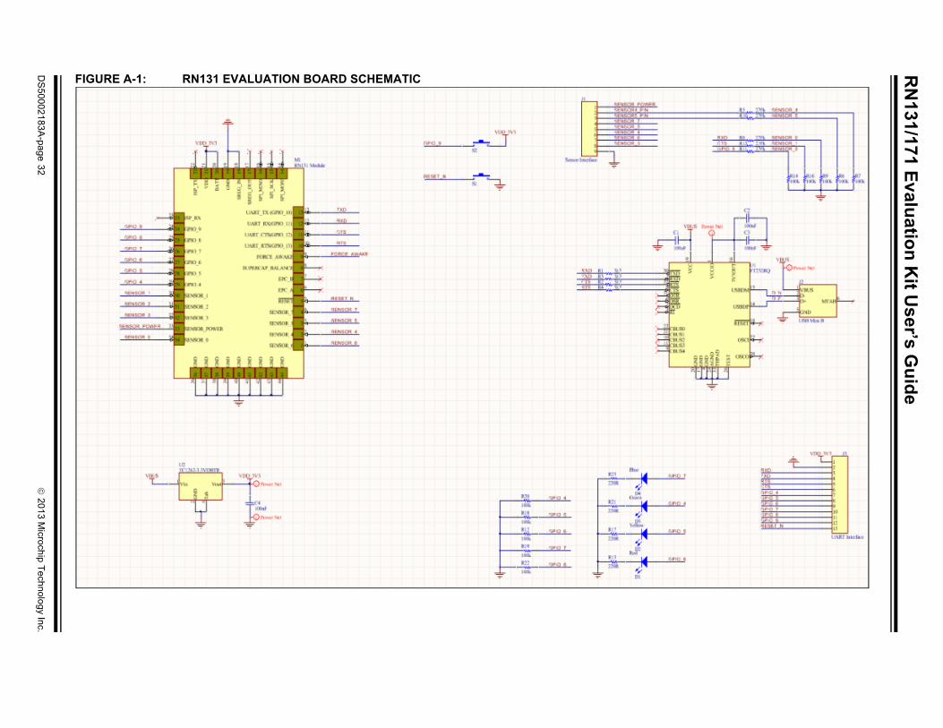
A.2 RN131 AND RN171 EVALUATION KITS SCHEMATIC
Figure A-1 and Figure A-2 show the Evaluation Boards schematic.
2013 Microchip Technology Inc. DS50002183A-page 31
RN
131/171 Evalu
ation
Kit U
ser’s Gu
ide
DS
50002183A
-page 32
2013 M
icrochip Technolo
gy Inc.
FIGURE A-1: RN131 EVALUATION BOARD SCHEMATIC

Ap
pen
dix A
2013
Microchip T
echnology Inc.D
S5
0002183A-p
age 33
FIG
URE A-2: RN171 EVALUATION BOARD SCHEMATIC
RN131/171 Evaluation Kit User’s Guide
A.3 RN131 AND RN171 EVALUATION KITS PCB LAYOUT AND ASSEMBLY DRAWINGS
The RN131/171 Evaluation Board is a 2-layer, FR4, 0.062 inch, plated through a hole PCB construction. Figure A-3 through Figure A-14 show the PCB constructions and Assembly Drawings.
FIGURE A-3: RN131 EVALUATION BOARD TOP SILKSCREEN
FIGURE A-4: RN131 EVALUATION BOARD BOTTOM SILKSCREEN
DS50002183A-page 34 2013 Microchip Technology Inc.

Appendix A
FIGURE A-5: RN131 EVALUATION BOARD TOP COPPER
FIGURE A-6: RN131 EVALUATION BOARD BOTTOM COPPER
2013 Microchip Technology Inc. DS50002183A-page 35

RN131/171 Evaluation Kit User’s Guide
FIGURE A-7: RN131 EVALUATION BOARD TOP ASSEMBLY
FIGURE A-8: RN131 EVALUATION BOARD BOTTOM ASSEMBLY
DS50002183A-page 36 2013 Microchip Technology Inc.

Appendix A
FIGURE A-9: RN171 EVALUATION BOARD TOP SILKSCREEN
FIGURE A-10: RN171 EVALUATION BOARD BOTTOM SILKSCREEN
2013 Microchip Technology Inc. DS50002183A-page 37

RN131/171 Evaluation Kit User’s Guide
FIGURE A-11: RN171 EVALUATION BOARD TOP COPPER
FIGURE A-12: RN171 EVALUATION BOARD BOTTOM COPPER
DS50002183A-page 38 2013 Microchip Technology Inc.

Appendix A
FIGURE A-13: RN171 EVALUATION BOARD TOP ASSEMBLY
FIGURE A-14: RN171 EVALUATION BOARD BOTTOM ASSEMBLY
2013 Microchip Technology Inc. DS50002183A-page 39

RN131/171 Evaluation Kit User’s Guide
A.4 RN131 AND RN171 EVALUATION KITS BILL OF MATERIALSTABLE A-1: RN131 EVALUATION BOARD BILL OF MATERIALS (BOM)
Reference Value Description Vendor Vendor P/N
C1, C2, C3 100 nF Cap ceramic, -20%, 80%, 16V, Y5V, 0402
Yageo CC0402ZRY5V7BB104
C4 100 nF Cap ceramic, -20% / 80%, 16V, Y5V, 0603
Yageo CC0603ZRY5V7BB104
D1 Red Clear, Red LED, 10 mA, 1.8V, 638 nm, 130 degrees, 1206
Lite-On Inc LTST-C150CKT
D2 Yellow Clear, Yellow LED, 10 mA, 2.1V, 588 nm, 130 degrees, 1206
Lite-On Inc LTST-C150YKT
D3 Green Clear, Green LED, 10 mA, 2.1V, 569 nm, 130 degrees, 1206
Lite-On Inc LTST-C150GKT
D4 Blue Clear, Blue LED, 20 mA, 3.3V, 470 nm, 130 degrees, 1206
Lite-On Inc LTST-C150TBKT
J2 USB Mini B CONN USB RCPT MINI B 5PS R/A SMD
JAE DX2R005HN2E700
M1 — RN131 Module Microchip RN-131
R1, R2, R3, R4
3k3 Res, 5%, 0.1W, 0402 Panasonic - ECG ERJ-2GEJ332X
R5, R8, R10, R11, R15
220k Res, 5%, 0.1W, 0402 Panasonic - ECG ERJ-2GEJ224X
R6, R7, R9, R12, R14, R16, R18, R19, R20, R22
100k Res, 5%, 0.1W, 0402 Panasonic - ECG ERJ-2GEJ104X
R13, R17, R21, R23
220R Res, 5%, 0.1W, 0402 Panasonic - ECG ERJ-2GEJ221X
S1, S2 Push button SWITCH TACTILE SPST-NO 0.05A 32V
C&K Components KSR211J
U1 FT232RQ IC USB FS SERIAL UART 32-QFN FTDI FT232RQ-REEL
U2 TC1262-3.3V Linear Voltage Regulator Microchip TC1262-3.3VDBTR
DS50002183A-page 40 2013 Microchip Technology Inc.

Appendix A
TABLE A-2: RN171 EVALUATION BOARD BILL OF MATERIALS (BOM)
Reference Value Description Vendor Vendor P/N
C1 100 nF Cap ceramic, -20% / 80%, 16V, Y5V, 0603
Yageo CC0603ZRY5V7BB104
C2, C3, C11 10 uF Cap ceramic, 20%, 6.3V, X5R, 0603
TDK Corporation C1608X5R0J106M
C4, C5, C6 100 nF Cap ceramic, -20%, 80%, 16V, Y5V, 0402
Yageo CC0402ZRY5V7BB104
D1 Red Clear, Red LED, 10 mA, 1.8V, 638 nm, 130 degrees, 1206
Lite-On Inc LTST-C150CKT
D2 Yellow Clear, Yellow LED, 10 mA, 2.1V, 588 nm, 130 degrees, 1206
Lite-On Inc LTST-C150YKT
D3 Green Clear, Green LED, 10 mA, 2.1V, 569 nm, 130 degrees, 1206
Lite-On Inc LTST-C150GKT
D4 Blue Clear, Blue LED, 20 mA, 3.3V, 470 nm, 130 degrees, 1206
Lite-On Inc LTST-C150TBKT
D5, D6 PMEG2005CT,215
Dual Schottky diode, 1A, 20V, SOD-123F
NXP Semiconductor PMEG2005CT,215
J6 USB Mini B CONN USB RCPT MINI B 5PS R/A SMD
JAE DX2R005HN2E700
L1 1uH INDUCTOR 1.0UH 30% SMD Taiyo Yuden NR3015T1R0N
M1 — RN171 Module Microchip RN-171
Q1, Q2 DMN2050L N MOSFET 5.9A, 20V, 29 mOhm, SOT23-3
Dioded Inc DMN2050L-7
R1, R2, R8, R17, R18
220k Res, 5%, 0.1W, 0402 Panasonic - ECG ERJ-2GEJ224X
R4, R6, R7, R9, R10, R12, R13, R14, R16, R19
100k Res, 5%, 0.1W, 0402 Panasonic - ECG ERJ-2GEJ104X
R5, R11, R15, R20
220R Res, 5%, 0.1W, 0402 Panasonic - ECG ERJ-2GEJ221X
R21, R22, R23, R24
3k3 Res, 5%, 0.1W, 0402 Panasonic - ECG ERJ-2GEJ332X
S1, S2 Push button SWITCH TACTILE SPST-NO 0.05A 32V
C&K Components KSR211J
U1 TC1262-3.3V Linear Voltage Regulator Microchip TC1262-3.3VDBTR
U2 FT232RQ IC USB FS SERIAL UART 32-QFN FTDI FT232RQ-REEL
2013 Microchip Technology Inc. DS50002183A-page 41

RN131/171 Evaluation Kit User’s Guide
A.5 RN131 AND RN171 EVALUATION KITS PHYSICAL DIMENSIONS
Figure A-15 and Figure A-16 show the physical dimensions of the RN131 and RN171 Evaluation Boards.
FIGURE A-15: RN131 EVALUATION BOARD PHYSICAL DIMENSIONS
DS50002183A-page 42 2013 Microchip Technology Inc.

Appendix A
FIGURE A-16: RN171 EVALUATION BOARD PHYSICAL DIMENSIONS
2013 Microchip Technology Inc. DS50002183A-page 43

RN131/171 Evaluation Kit User’s Guide
NOTES:
DS50002183A-page 44 2013 Microchip Technology Inc.

RN131/171 EVALUATION KITUSER’S GUIDE
2013 Microchip Technology Inc. DS50002183A-page 45
AAd hoc parameters................................................... 24Analog-to-Digital Converter (ADC)........................... 29ASCII commands ..................................................... 13Assembly Drawings.................................................. 34
BBill of Materials (BOM) ..........................................8, 31
CCOM Port ................................................................. 18Command mode ...................................................... 21Customer Notification Service.................................. 10Customer Support .................................................... 10
DData mode ............................................................... 21Demonstration Application ..................................19, 29Documentation
Conventions........................................................ 8Layout ................................................................. 7
EExplorer 16 Development Board................................ 9
FFTDI drivers ............................................................. 19FTP client ................................................................. 13FTP host address..................................................... 24
IIEEE 802.11 b/g transceiver .................................... 13Internet Address....................................................... 10
LLEDs ........................................................................ 18
MMicrochip Internet Web Site ..................................... 10MRF24XA .................................................................. 7
PPCB constructions ................................................... 34PCB layers ............................................................... 34PCB layout ............................................................8, 31Physical Dimensions................................................ 42PICDEM™ PIC18 Explorer ........................................ 9
RReal-time clock ........................................................ 13Recommended Reading ............................................ 9Red LED .................................................................. 25RN131/171 Evaluation Board .................................... 7RoHS compliant ....................................................... 13
SSMA Connectors ...................................................... 18SoftAP mode ............................................................ 13
TTCP/IP networking ................................................... 13Telnet ....................................................................... 13Terminal Emulator Application ................................. 20
UU.FL. connector........................................................ 13UART (RS232) ........................................................... 7USB cable ................................................................ 13USB Connector ........................................................ 18USB interface ............................................................. 7USB-to-serial cable .................................................. 22
WWarranty Registration ................................................ 9Wi-Fi Alliance ........................................................... 13WPA2-PSK............................................................... 13WPS mode ............................................................... 29WWW Address......................................................... 10
Index

DS50002183A-page 46 2013 Microchip Technology Inc.
AMERICASCorporate Office2355 West Chandler Blvd.Chandler, AZ 85224-6199Tel: 480-792-7200 Fax: 480-792-7277Technical Support: http://www.microchip.com/supportWeb Address: www.microchip.com
AtlantaDuluth, GA Tel: 678-957-9614 Fax: 678-957-1455
BostonWestborough, MA Tel: 774-760-0087 Fax: 774-760-0088
ChicagoItasca, IL Tel: 630-285-0071 Fax: 630-285-0075
ClevelandIndependence, OH Tel: 216-447-0464 Fax: 216-447-0643
DallasAddison, TX Tel: 972-818-7423 Fax: 972-818-2924
DetroitFarmington Hills, MI Tel: 248-538-2250Fax: 248-538-2260
IndianapolisNoblesville, IN Tel: 317-773-8323Fax: 317-773-5453
Los AngelesMission Viejo, CA Tel: 949-462-9523 Fax: 949-462-9608
Santa ClaraSanta Clara, CA Tel: 408-961-6444Fax: 408-961-6445
TorontoMississauga, Ontario, CanadaTel: 905-673-0699 Fax: 905-673-6509
ASIA/PACIFICAsia Pacific OfficeSuites 3707-14, 37th FloorTower 6, The GatewayHarbour City, KowloonHong KongTel: 852-2401-1200Fax: 852-2401-3431
Australia - SydneyTel: 61-2-9868-6733Fax: 61-2-9868-6755
China - BeijingTel: 86-10-8569-7000 Fax: 86-10-8528-2104
China - ChengduTel: 86-28-8665-5511Fax: 86-28-8665-7889
China - ChongqingTel: 86-23-8980-9588Fax: 86-23-8980-9500
China - HangzhouTel: 86-571-2819-3187 Fax: 86-571-2819-3189
China - Hong Kong SARTel: 852-2943-5100 Fax: 852-2401-3431
China - NanjingTel: 86-25-8473-2460Fax: 86-25-8473-2470
China - QingdaoTel: 86-532-8502-7355Fax: 86-532-8502-7205
China - ShanghaiTel: 86-21-5407-5533 Fax: 86-21-5407-5066
China - ShenyangTel: 86-24-2334-2829Fax: 86-24-2334-2393
China - ShenzhenTel: 86-755-8864-2200 Fax: 86-755-8203-1760
China - WuhanTel: 86-27-5980-5300Fax: 86-27-5980-5118
China - XianTel: 86-29-8833-7252Fax: 86-29-8833-7256
China - XiamenTel: 86-592-2388138 Fax: 86-592-2388130
China - ZhuhaiTel: 86-756-3210040 Fax: 86-756-3210049
ASIA/PACIFICIndia - BangaloreTel: 91-80-3090-4444 Fax: 91-80-3090-4123
India - New DelhiTel: 91-11-4160-8631Fax: 91-11-4160-8632
India - PuneTel: 91-20-2566-1512Fax: 91-20-2566-1513
Japan - OsakaTel: 81-6-6152-7160 Fax: 81-6-6152-9310
Japan - TokyoTel: 81-3-6880- 3770 Fax: 81-3-6880-3771
Korea - DaeguTel: 82-53-744-4301Fax: 82-53-744-4302
Korea - SeoulTel: 82-2-554-7200Fax: 82-2-558-5932 or 82-2-558-5934
Malaysia - Kuala LumpurTel: 60-3-6201-9857Fax: 60-3-6201-9859
Malaysia - PenangTel: 60-4-227-8870Fax: 60-4-227-4068
Philippines - ManilaTel: 63-2-634-9065Fax: 63-2-634-9069
SingaporeTel: 65-6334-8870Fax: 65-6334-8850
Taiwan - Hsin ChuTel: 886-3-5778-366Fax: 886-3-5770-955
Taiwan - KaohsiungTel: 886-7-213-7828Fax: 886-7-330-9305
Taiwan - TaipeiTel: 886-2-2508-8600 Fax: 886-2-2508-0102
Thailand - BangkokTel: 66-2-694-1351Fax: 66-2-694-1350
EUROPEAustria - WelsTel: 43-7242-2244-39Fax: 43-7242-2244-393Denmark - CopenhagenTel: 45-4450-2828 Fax: 45-4485-2829
France - ParisTel: 33-1-69-53-63-20 Fax: 33-1-69-30-90-79
Germany - MunichTel: 49-89-627-144-0 Fax: 49-89-627-144-44
Italy - Milan Tel: 39-0331-742611 Fax: 39-0331-466781
Netherlands - DrunenTel: 31-416-690399 Fax: 31-416-690340
Spain - MadridTel: 34-91-708-08-90Fax: 34-91-708-08-91
UK - WokinghamTel: 44-118-921-5869Fax: 44-118-921-5820
Worldwide Sales and Service
11/29/12