RHINO BASICS - materiability.com
20
RHINO BASICS Material and Technology Prof. Dr. Manuel Kretzer
Transcript of RHINO BASICS - materiability.com

RHINO BASICSMaterial and TechnologyProf. Dr. Manuel Kretzer

2
1. The Rhino interface 1.1 Menu 1.2 Viewports 1.3 Command Prompt 1.4 Toolbars 1.5 Panels
2. Select a Viewport
3. Move around
4. Give a Command 4.1 by Menu 4.2 by Toolbar 4.3 by command prompt
5. Snaps and Gumball
6. Select Objects
7. Move Objects
Further info and credits
Tutorial prepared by Marek Runde. Revised by Nadia Elkady, MA.
For more tutorials visit:
https://www.rhino3d.com/learn/
https://www.rhino3dhelp.com/
Youtube is also a great source for Rhino tutorials.
What you are about to learn:

3
1 Command bar
Toolbars
Viewports
Panels
This is where commands can be typed out. After the command has been selected, several prompts related to this action will be displayed, allowing for further setting selection.
The sidebar is where tool-bar groups are displayed, it consists of graphical icons that symbolize commands. Some icon buttons also include a small arrow, this signifies further commands. Right clicking on the icons reveals a drop down menu displaying them.
The sidebar is where tool-bar groups are displayed, it consists of graphical icons that symbolize commands. Some icon buttons also include a small arrow, this signifies further commands. Right clicking on the icons reveals a drop down menu displaying them.
All geometry can be seen, edited, and moved through the viewports.
You can access layers, properties and other options in the tabbed panels.
1
2
2
3
3
4
4
1. The Rhino interface

4
Since Rhino is a three dimensional program, you need to be able to look on your object from different angles.
Switching viewports can be crucial to your work flow. It ensures that you have a full scope of what you are working on and that all geometry is where you intended it to be.
Double-clicking on the name of a Viewport enlarges it and gives you a closer look at the se-lected view, to return to the 4-View Viewport, double click on the name again.
Hovering over the borders of the viewports gives you the option of changing the sizes of the panels according to your work flow preferences.
The bottom left corner of each viewport displays the axes you are working with.
Refrain from working solely in the Perspective view. This is to avoid inaccuracy due to false judgment of position and distance.
Tip:
2. Select a viewport

5
Moving within the viewport is done using your mouse. Whilst in the viewport you want to pan around, simply click and hold the right button on your mouse and drag it to the desired posi-tion.
To move the plane, press the shift button while moving the mouse.
In case of viewport coordination confusion, select your geometry and click on the “zoom selected” option. This will center your object in the active viewport.
Tip:
3. Move around

6
The method you use to pick your command is based on your personal preference. You can use the menu at the top of your window, select commands from the sidebar, type in commands, or even use shortcuts.
You can find out whether or not your performed command was successful by reading the gray bar at the bottom (Mac) or the text box above the command bar (Windows)
Pressing ESC cancels every com-mand.
Pressing enter or right clicking re-peats your last command.
Drag down the command line to view the command history.
Tip:
4. Give a command
7
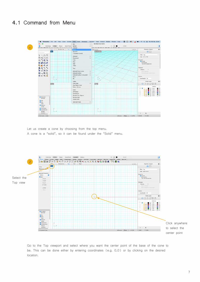
Let us create a cone by choosing from the top menu. A cone is a “solid”, so it can be found under the “Solid” menu.
Go to the Top viewport and select where you want the center point of the base of the cone to be. This can be done either by entering coordinates (e.g. 0,0) or by clicking on the desired location.
1
4.1 Command from Menu
2
Select the Top view
Click anywhere to select the center point

8
Now you choose the radius for the base. You can do so by typing it in or by simply dragging the mouse to the desired point and clicking.
Switch to the Front viewport. Now set the tip point of the cone. Do so by typing in the coordi-nates or by dragging the cursor and clicking to draw the cone.
3
4
switch to top view
Still in the Top view
Drag the cursor and click to set the radius

9
Now switch to the Viewport 4-View or to the Perspective viewport to see the result of your work.
4.2 Command by Toolbars
5
Try out the three dimensional “cam-era” in the Perspective viewport.
Check out what the “zoom selected” function does.
Use the “shaded” preview by click-ing on the grey marble in your top toolbar.
Tip:
Select the cone and activate the shaded view

10
Toolbars provide a graphical interface to the commands.
Now we will draw a line. Go to the icon for lines in your toolbar. By holding down the mouse button you can see what other options there are. We are going for “control point curve”.
Start the curve in the Top viewport. Make a few points by clicking the mouse.
1
2
Select the icon for “line”
Draw a few points in the Top viewport
11
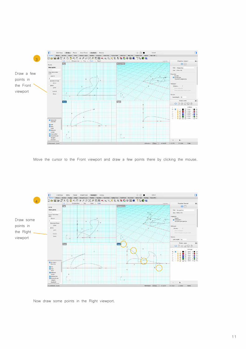
Move the cursor to the Front viewport and draw a few points there by clicking the mouse.
Now draw some points in the Right viewport.
3
4
Draw some points in the Right viewport
Draw a few points in the Front viewport

12
By right-clicking the mouse or pressing the space bar you finish the line.
Switch to the Perspective viewport and select your curve. Hit the “zoom selected” button and look at the outcome of your efforts. Drag with the right mouse button clicked to pan and have a look at the curve from all angles.
5
6
Look at what you drew in the Perspec-tive Viewport
Press the spacebar or rightclick your mouse

13
Click at the command prompt, and type “Sphere”. When you type the first letters of a command, a list of possible commands appears. The most likely candidate auto-completes. When the com-mand name Sphere appears, press Enter, or click on Sphere from the list. The default option for the Sphere command is Center, Radius. This means that these are the two variables you can control. You must first identify the location of the center of the sphere, then you can type in the length of the radius.
Identify the center point of the sphere at any point in the Perspective viewport by clicking your mouse. Typing in the coordinates is always an option if you need the point at a specific location.
4.3 Command by prompt
1
2
Type in “sphere” in the command prompt
We use the Center option to draw the sphere.Other options for the command are listed here.
Draw the center of the sphere by clicking into the plane in the Perspective viewport
14
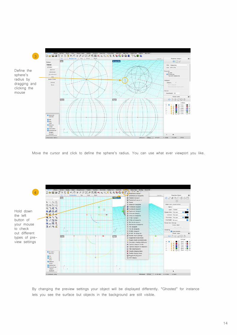
Move the cursor and click to define the sphere’s radius. You can use what ever viewport you like.
By changing the preview settings your object will be displayed differently. “Ghosted” for instance lets you see the surface but objects in the background are still visible.
3
4
Hold down the left button of your mouse to check out different types of pre-view settings
Define the sphere’s radius by dragging and clicking the mouse

15
Using your Object Snap menu is a necessity when it comes to 3D modeling. Although all geome-try can be placed freely along the plane, Snaps are the only way to ensure that points, lines, and any other geometry are actually connected. E.g. If you draw a line, and want to connect the end of that line to another curve, you must have your End Osnap activated.
The Gumball function allows for further transformation and manipulation of your geometry. When you select an object with gumball activated, you will see arrows, cubes, and arcs. Arrows al-low you to move the object along the X, Y, and Z axes. Arcs let you rotate the object, and the cubes are used to scale the object.
5. Snaps and Gumball
This is the Gumball
Snaps can be activated here

16
Select single objects by clicking on them.In case you want to select more than one, hold down the left mouse button and drag it across the Viewport. Release the button and things inside the rectangle get selected.
Depending on the direction you drag the cursor across, you can give yourself more control over what you select.
Drag from left to right: things inside the rectangle get selected.Drag from right to left: everything touched by the rectangle gets selected.
Drag from left to right:
Things fully inside the rectangle get selected
6. Select objects
Drag from left to right:
Things touched by the rectangle get selected

17
There are many ways to move objects. One is to select an object and simply drag it across the plane with the left mouse button pressed.
Let go of the button and the object is placed.Holding down shift while moving locks the direction you move the object.This method is rather inaccurate though.
7. Move objects
Keep the mouse’ left button pressed and drag the object across the plain

18
Gumball works almost the same way but lacks precision as well.Grab one of the arrows and move the object with the mouse button engaged.
A more accurate and therefore better way to move geometry is by using the move command. Start by typing in “move”.
Use Gum-ball arrows to move an object
Type in “move” into the command prompt

19
Then select one point of the object as reference. You can then either type in the distance you want to move by, or simply click on the point you want your geometry to be.
Now tell Rhino where you want to have the point relocated to by typing in the new coordinates. Press enter and the object will be moved to it’s new location.
Type in the new coordinates
Select the point you want to be moved

20
Prof. Dr. sc. Manuel Kretzer Material and Technology | Materiability Research GroupDessau Department of Design | Anhalt University of Applied Scienceswww.materiability.com