
Revised: February 2009 Model 2023ETS, ETSB 16oz....
24
Part No 67837 Revised: February 2009 Model 2023ETS, ETSB 16oz. Popcorn Machine Instruction Manual Cincinnati, OH 45241-4807 USA
Transcript of Revised: February 2009 Model 2023ETS, ETSB 16oz....
Part No 67837 Revised: February 2009
Model 2023ETS, ETSB 16oz. Popcorn Machine
Instruction Manual
Cincinnati, OH 45241-4807 USA

SAFETY PRECAUTIONS

2023ETS & 2023ETSB
3
INSTALLATION INSTRUCTIONS
Inspection of Shipment:
Unpack all cartons and check thoroughly for any damage that may have occurred during transit. Damage claims should be filed immediately with the transportation company. Gold Medal Products is not responsible for damage that occurs in transit.
Setup:
Your new 16 oz. Astro-Pop is completely assembled and tested at the factory. Remove all packing material and tape before starting operation.
Electrical Requirements:
The following power supply must be provided: 120 VAC, 60 Hz., 30 Amp Fused Circuit – NEMA 5-30R Receptacle provided with the machine.
The 2023ETS has a current draw of 24 Amps.
Your electrician must furnish sufficient power for proper machine operation. We recommend this popper be on a dedicated and protected circuit. Failure to wire properly will void the warranty and may result in damage to the machine.
It is Gold Medal Products Company’s recommendation that this machine be plugged directly into a wall outlet. The use of extension cords is not recommended due to safety concerns, and may cause sacrificed and/or reduced performance.
Before Plugging in the Machine:
1. Make sure that the wall outlet can accept the three (3) prong grounded power supply cord.
2. The wall outlet must have the proper polarity. If in doubt, have a competent electrician inspect the outlet and correct if necessary.

2023ETS & 2023ETSB
4
Operating Instructions – Controls and Their Functions
Oil System Master Switch: Sends power to the oil pump, either the Bucket Pump or Bag-in-Box models. The warmer/blower on the oil pump is activated. The warmer/blower on the oil pump will keep coconut popping oil in liquid form if the doors on the base are kept closed. It may be desirable to keep this switch on at night, if you have problems keeping the coconut oil liquified. Coconut oil will congeal at temperatures below approximately 76º F [24º C].
“Red” Oil Dispense Momentary Switch: When pushed, will dispense the predetermined amount of oil into the kettle. See page 6 of this manual for oil setting instructions.
Light & Warmer Switch:
This switch operates the interior light, and the forced air popcorn crisping system.
Kettle Motor Switch: This switch operates the popcorn agitator motor. This switch must be ON at all times when popcorn (popped and un-popped) is present in the kettle. This switch also activates the exhaust fan.
Kettle Heat Switch:
This switch turns on the heat elements, located in the popcorn kettle, by sending power to the “Big Eye” electronic control system.
Yellow Light & Audible Signal (LOAD – DUMP) :
The Astro-Pop is equipped with the state-of-the-art “Big Eye” electronic control that “watches your popcorn machine” to deliver optimum popping performance.
The “Big Eye” control will signal the operator to: 1. Load the corn and oil or 2. Dump the popped corn from the kettle or 3. Turn off the kettle heat switch if they are done popping corn
Oil Dispense Momentary Switch
p/n 41031
Oil System Master Switch
p/n 42798
Light Switch
p/n 42798
Warmer Switch
p/n 42798
Kettle Motor Switch
p/n 42798
Kettle Heat Switch
p/n 42798
Pilot Light - Green
p/n 48660
Pilot Light - Amber
p/n 55039

2023ETS & 2023ETSB
5
Amount of Popcorn and Oil:
The 16 oz. Astro-Pop is equipped with a 16 ounce corn measure cup. Gold Medal Products Company recommends the use of flavored and colored coconut oil. Coconut oil does not leave black deposits in the kettle like other oils.
Corn Charge: 16 Oz. (355 ml) (Use the supplied corn measure cup.)
Oil Charge: 4-5 Oz. Flavacol (Salt): 4 Tablespoons (11 cc. – Use the supplied salt scoop.)

2023ETS & 2023ETSB
6
Setting the Amount of Popping Oil with a Gold Medal BIB System
Note: When connecting the bag-in-box system, you must be sure to connect the bag connectors as shown in the picture to the left.
With the EZ-Set Timer System, it is not necessary to set a manual timer. To adjust the oil amount, follow these instructions: Holding down the RED Oil Dispense push button (on the popper) while turning on the Oil System Master switch (on the popper) puts the unit in the program mode. The oil light (on the popper) will start to blink off and on indicating that the timer is in the program mode.
When in the program mode press and release the oil Dispense switch to start the oil flowing. When the correct amount of oil has been dispensed into the measuring cup push the oil Dispense switch again to stop the oil flow. The oil amount can be “topped off” by pushing the oil Dispense switch on/off as many times as needed to finalize the oil amount. Turning the Oil System Master switch off and then back on puts the unit in the regular mode. The unit will now dispense the “programmed” amount of oil when the oil Dispense switch is pushed. The oil light will light only when the oil pump is on.
You will need to perform this procedure with the oil lines full of oil. Otherwise, you are setting both the amount of oil that goes in the kettle and the amount of oil required to fill the lines. Just fill the lines using the process above, then reset the amount as described above.
NOTES: Model 2257D is has the capability of “remembering” two different settings for poppers with the “Salt/Sweet” option or “Flexi-Pop option. - For Salt/Sweet models, just put the switch in the “salt” position, and set the oil amount as described above. Then put the switch in the “sweet” position and repeat the setting procedure. The pump will remember both settings. - For Flexi-Pop models, just put the “Load” switch in one position, 32oz. for example, then set the oil amount. Then put the load switch in the other position, 18oz. for example. And repeat the setting procedure. - Model 2457 is the heated line option for the 2257 pump.
The dead-leg connector (With only one hose connected to it) must be installed on the top box.
The Pass-thru connector (With two hoses connected to it) must be installed on the bottom box.
The Pass-thru connector (With two hoses connected to it) must be installed on the bottom box.

2023ETS & 2023ETSB
7
Preventing and Troubleshooting Oil Delivery Issues It may occur at times that the Bag-In-Box oil pumping system does not deliver oil to the kettle, or delivers it in incorrect amounts. This section is intended to list the most common causes of these problems, and the procedures necessary to prevent and, if necessary, correct them. Oil Temperature – Coconut oil becomes a solid at temperatures above the average room temperature. For this reason, it is necessary to ensure that the oil has been permitted to come to working temperature before attempting to pump it through the system. If the machine has not been used for several days, the oil master switch should be turned on the night before it is expected that the machine will be used. For machines which are in daily use, even if not round the clock, leave the oil master switch on at all times and keep the base cabinet doors closed to prevent the oil from becoming solid. Bag-In-Box Mounting – Because the bag’s dispensing connector is offset toward the bottom of the box, to permit free oil flow and complete emptying of the oil from the bag, the box should never be mounted upside down. Most boxes supplied will be clearly marked as to which side should be up during dispensing. (Note that in some cases the box is intended to be stored with one side up, but to be turned and used in dispensing with the other side up.) Be sure to double check to ensure that the box is mounted in the correct dispensing orientation. You may encounter boxes with no clear markings to indicate dispensing orientation. A reliable guide in this case (and also for those boxes which are marked), is the direction that the top side flap of the corrugated box is folded. When the box is properly mounted for dispensing, the top side flap will fold down from the top edge of the box, so that if one were to attempt to separate the flap it would be necessary to pull up from the bottom edge. See the illustrations below.
This edge is seamless. The side
flap folds down from this edge.
The bottom of the side flap can be seen to be open, not seamless,
held in position only by
TOP
Rear Side Flap
Front Side Flap
Top Side Flap
TOP
Looking at the box from the bottom, the front and rear side flaps can be seen folded along the side of the box toward the middle, and the outer, top side
flap folded down to cover them.
NOTE
The Bag-In-Box oil pumping system is NOT designed to function when the bag has
been removed from the box. Service results in such a situation are
unpredictable. Do not attempt to operate the system with a bag which has been
removed from the box.
2023ETS & 2023ETSB
8
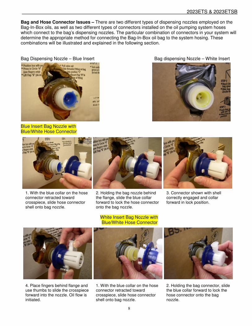
Bag and Hose Connector Issues – There are two different types of dispensing nozzles employed on the Bag-In-Box oils, as well as two different types of connectors installed on the oil pumping system hoses which connect to the bag’s dispensing nozzles. The particular combination of connectors in your system will determine the appropriate method for connecting the Bag-In-Box oil bag to the system hosing. These combinations will be illustrated and explained in the following section. Bag Dispensing Nozzle – Blue Insert Bag dispensing Nozzle – White Insert Blue Insert Bag Nozzle with Blue/White Hose Connector
White Insert Bag Nozzle with Blue/White Hose Connector
1. With the blue collar on the hose connector retracted toward crosspiece, slide hose connector shell onto bag nozzle.
2. Holding the bag nozzle behind the flange, slide the blue collar forward to lock the hose connector onto the bag nozzle.
3. Connector shown with shell correctly engaged and collar forward in lock position.
4. Place fingers behind flange and use thumbs to slide the crosspiece forward into the nozzle. Oil flow is initiated.
1. With the blue collar on the hose connector retracted toward crosspiece, slide hose connector shell onto bag nozzle.
2. Holding the bag connector, slide the blue collar forward to lock the hose connector onto the bag nozzle.

2023ETS & 2023ETSB
9
Blue Insert Bag Nozzle
with Gray Hose Connector
White Insert Bag Nozzle with Gray Hose Connector
3. Connector shown with shell correctly engaged and collar forward in lock position. Oil flow commences. Do not slide crosspiece forward.
1. Grasp the bag nozzle and slide the gray hose connector on from the side.
2. With the hose connector in place, place fingers behind flange on connector and press plunger forward to lock.
3. Connector shown with shell correctly engaged and plunger forward in lock position. Oil flow commences.
1. Grasp the bag nozzle and slide the gray hose connector on from the side.
2. With the hose connector in place, place fingers behind flange on connector and press plunger forward to lock.
3. Connector shown with shell correctly engaged and plunger forward in lock position. Since the White Insert Bag Nozzle is not designed to work with the insert pressed forward, this configuration may or may not work. If it does not, remove the gray hose connector and order the blue hose connector from Gold Medal.
NOTE: If the oil does not flow after engaging plunger on gray hose connector, or if the crosspiece is inadvertently pushed forward when using the blue hose connector with the white insert nozzle, the nozzle center slider insert will be left pushed back into the bag, as shown above left.
To correct this, place fingers behind nozzle as shown above right. You will feel the center slider protruding slightly into the bag. Holding the nozzle body from the front, press the slider from the back side of the nozzle until it snaps outward into its correct position. The nozzle is now ready to be used with a blue hose connector.

2023ETS & 2023ETSB
10
Popping Instructions
1. Turn both the KETTLE HEAT and KETTLE STIR MOTOR switches to the ON position, making sure that the (2) spur gears are engaged.
2. Wait until the Yellow Light and Audible Signal activate.
3. Load both a full corn/oil charge and Flavacol Seasoning Salt into the kettle. Close the
lids.
4. When the corn has finished popping, the Yellow Light and Audible Signal will “tell you” to dump the kettle.
Remember:
If the Yellow Load - Dump light is turned on and the Signal is sounding, one of the following actions should be taken:
1. Load the corn and oil or 2. Dump the popped corn from the kettle or 3. Turn off the kettle heat switch when popping of corn is complete
On the final kettle of corn, it is a good idea to turn the KETTLE HEAT switch OFF just as the lids are forced open by the popping corn. This procedure saves electricity since the kettle has plenty of heat, and eliminates smoke/odor from any oil residue that remains after you have finished popping.
When you are finished popping, make sure “KETTLE HEAT” and “KETTLE MOTOR” switches are turned “OFF”.
NEVER LEAVE THE HEAT ON WHEN YOU ARE NOT POPPING CORN.

2023ETS & 2023ETSB
11
Care and Cleaning DAILY: Clean the Kettle
1. As you pop corn, wipe the kettle with a clean cloth. It is easy to keep the outside clean when the kettle is warm and the oil is not baked on. CAUTION: The hot kettle will cause burns if you touch it with your hand. Allow the kettle to cool for at least 1 hour before attempting to clean.
2. After ending extended use, mix a gallon of Heat’n Kleen solution (2 tablespoons per gallon of water). Add 16 oz. of this solution into the kettle. Turn on the kettle heat. When the water starts to boil, turn off the kettle heat and allow the solution to work over-night.
3. Before next use, dump the solution into a bucket and wipe the inside of the kettle with a cloth. Make sure all of the solution goes into the bucket, and that you do not spill any into the interior cabinet of the machine.
DO NOT immerse the kettle in water or any other cleaning solution, this will void the warranty.
Clean the Popcorn Machine
1. Wipe the stainless steel parts with a clean cloth and cleaner designed for stainless steel. Do not use oven cleaners, as they will damage parts of the machine.
2. Ammonia cleaners will damage the plastic doors. Use only non-ammonia cleaners, such as
Gold Medal’s – Watchdog Glass Cleaner – item number 2588.

2023ETS & 2023ETSB
12
Filter Cleaning Instructions
Your popcorn machine is equipped with an efficient and durable filtration system. The filter should be cleaned every 1-2 weeks to maintain maximum efficiency. Follow the steps below for proper filter cleaning:
1. The filter is located on the inside of the popcorn machine, directly above the popping
kettle.
2. Remove the filter by gripping the filter itself, and pulling straight down. (As shown below.) 3. Clean the filter in warm soapy water, and allow to dry overnight. Replace the filter by
putting it into the slot, and pushing upward. (As shown below) Make sure the filter frame is flush with the roof of the machine. (As shown above)

2023ETS & 2023ETSB
13
MAINTENANCE INSTRUCTIONS

2023ETS & 2023ETSB
14
ORDERING SPARE PARTS
1. Identify the needed part by checking it against the photos, illustrations, and/or parts list. 2. When ordering, please include part number, part name, and quantity needed. 3. Please include your model name, serial number, and date of manufacture (located on the machine
nameplate) with your order. 4. Address all parts orders to:
Parts Department Gold Medal Products Co.
10700 Medallion Drive Cincinnati, Ohio 45241-4807
(800) 543-0862 (513) 769-7676
Fax: (513) 769-8500 E-mail: [email protected]
or, place orders online at:
Web Page: www.gmpopcorn.com

2023ETS & 2023ETSB
15
Temperature Control
The Astro-Pop 16 has an electronic kettle control with 2 thermocouples, one for control and one for limit. There are no mechanical thermostats in this kettle.
There are (4) factory adjustments on the control:
� Control temperature – do not adjust this one � Signal to dump – If you want the signal to dump to be a little sooner or later you can
adjust the potentiometer marked “kettle dump”. CW is sooner, CCW is later. � The patented overshoot circuit is tuned for the kettle, do not adjust this
potentiometer. � The audible signal to dump has three options; full volume, half volume, no sound (just
the yellow light). Adjustments are by jumper positions. This is set to full volume from the factory.
The control temperature is set at 440F, DO NOT ADJUST
The overshoot is set at (-20%), full CW position, DO NOT ADJUST
This is the “Kettle Dump” adjustment, and is factory set to signal when the kettle is ready to dump. Turning CW will signal sooner, CCW will signal later. If you need to adjust, make very small adjustments.
Remove this jumper for no sound
Remove this jumper for lower volume
It does not matter which TC goes to A or B. It does matter that the yellow leads go to the positive terminals.
Hot Lead is at L1, Neutral lead at L2.

2023ETS & 2023ETSB
16
Kettle Assembly – 56101E
Kettle with Bonded On Elements p/n 58216
Terminal Shunt Bar (2) p/n 77864
Gasket 16oz p/n 41598
Dump Handle Assy p/n 47102
Kettle Lead-in Cord Assy
p/n 62305
Kettle Shell S.S. p/n 41081
Junction Box p/n 47393
Cover is p/n 56108
2023ETS & 2023ETSB
17
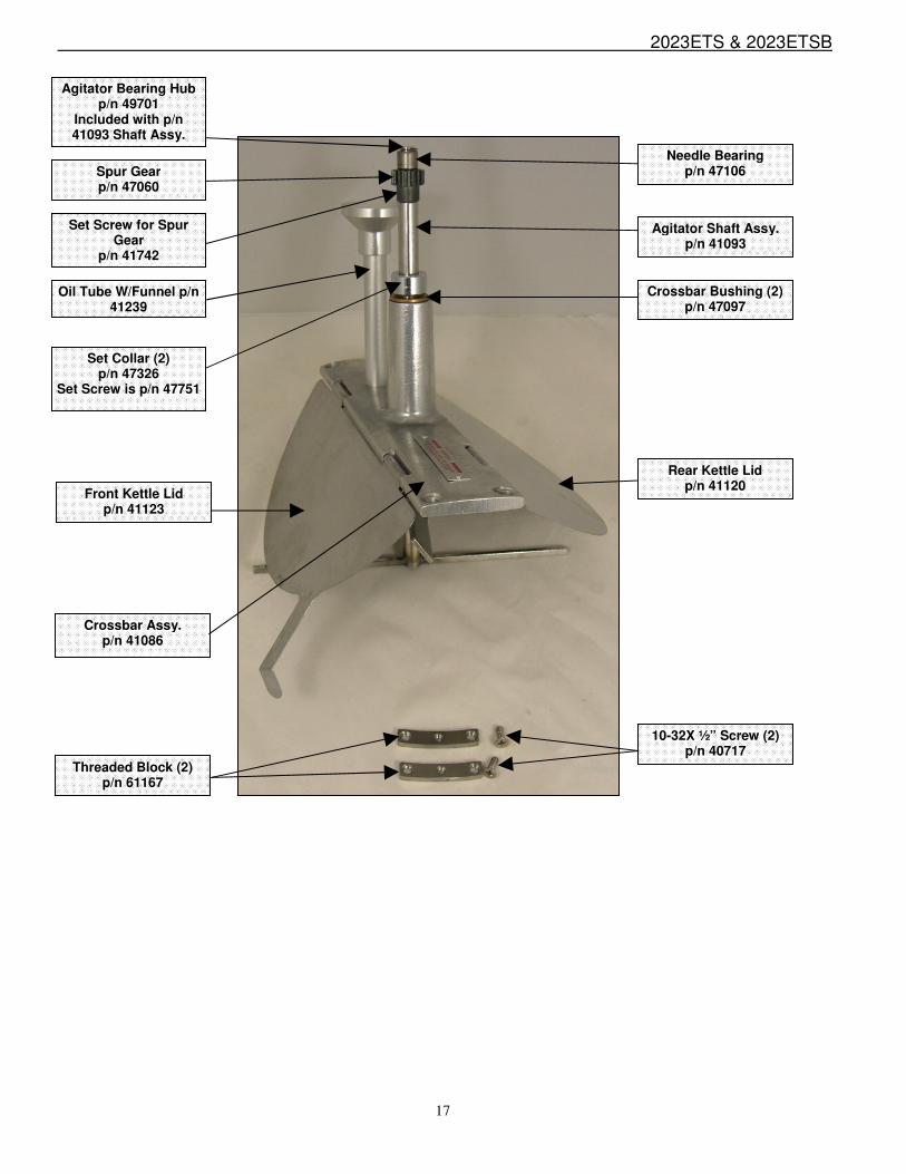
Agitator Bearing Hub p/n 49701
Included with p/n 41093 Shaft Assy.
Spur Gear p/n 47060
Oil Tube W/Funnel p/n 41239
Set Collar (2) p/n 47326
Set Screw is p/n 47751
Front Kettle Lid p/n 41123
Crossbar Assy. p/n 41086
Threaded Block (2) p/n 61167
Needle Bearing p/n 47106
Crossbar Bushing (2) p/n 47097
Rear Kettle Lid p/n 41120
10-32X ½” Screw (2) p/n 40717
Agitator Shaft Assy. p/n 41093
Set Screw for Spur Gear
p/n 41742

2023ETS & 2023ETSB
18
*Complete Door Hardware Kits Shown on bottom of Page 21.
Box Filter p/n 69850
5” X 10” X 2”
Oil Button Switch Box
p/n 48495 Label is p/n 48496
Gear Block p/n 67194
Coated Reflector
Flood p/n 47176
Hanger Arm Front p/n 47262
Dump Handle Assy
p/n 47102
Switch Box p/n 48543
Label is p/n 48542
Hanger Arm Rear p/n 47228
Dome p/n 41345NL
Magnetic Catch p/n 67561
Bracket is p/n 41340
Astro Door p/n 41014
Drop Panel Assy. p/n 41017
Kettle Complete p/n 56101E
Junction Box p/n 47393
Cover is p/n 56108
Label p/n 49393
Male Hinge Left p/n 41349
Female Hinge Left p/n 41352
Male Hinge Right p/n 41350
Female Hinge Right p/n 41351
Door Knob p/n 41013
Pilot Light -
Amber p/n 55039
Pilot Light - Green p/n 48660
Glass Dimensions for all three (3) pieces of popper glass are: 1/8” X 23 1/16” X 32 3/16” P/N 41190

2023ETS & 2023ETSB
19
Cabinet/Base Breakdown (2023ETSB)
Bin Retainer Assembly p/n 41215
Bottom Corn Pan p/n 41102
Old Maid Pan p/n 41838
Right Door p/n 37327
Swivel Caster (2) p/n 37513
Swivel Caster w/lock (2) p/n 37514
Wire Harness for Oil Pump
p/n 41499
Left Door p/n 37326
2023ETS & 2023ETSB
20
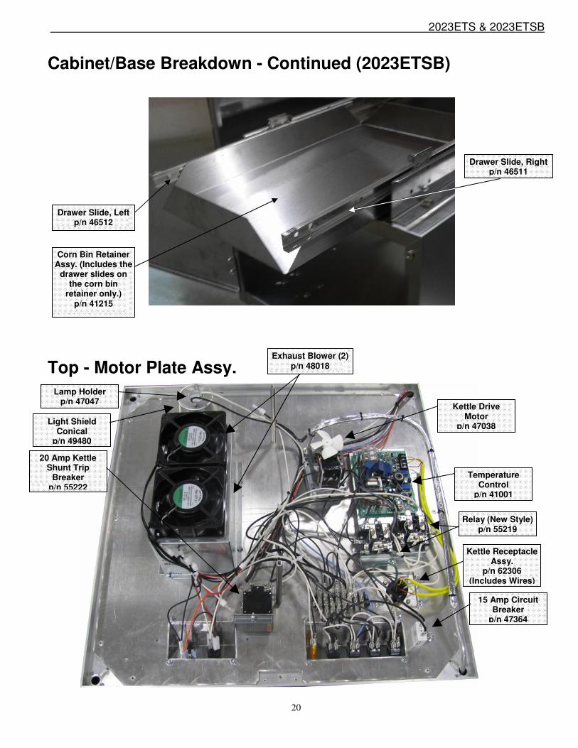
Cabinet/Base Breakdown - Continued (2023ETSB)
Top - Motor Plate Assy.
Drawer Slide, Left p/n 46512
Drawer Slide, Right p/n 46511
Corn Bin Retainer Assy. (Includes the
drawer slides on the corn bin
retainer only.) p/n 41215
Kettle Drive Motor
p/n 47038 Light Shield Conical
p/n 49480
Exhaust Blower (2) p/n 48018
Temperature Control
p/n 41001
Lamp Holder p/n 47047
Relay (New Style) p/n 55219
Kettle Receptacle Assy.
p/n 62306 (Includes Wires)
15 Amp Circuit Breaker
p/n 47364
20 Amp Kettle Shunt Trip
Breaker p/n 55222

2023ETS & 2023ETSB
21
Electrical Parts
Relay (Old Style) p/n 48590
Relay (New Style) p/n 55219
Warmer Blower Assy. (Complete)
p/n 47563
{ }Complete Door Hardware Kit LH
p/n 47054
Complete Door Hardware Kit RH
p/n 47055
Motor, Warmer – 115V
p/n 47356
Blower Wheel p/n 41113
Female Cordset p/n 61021
(Male Cordset, located in the bottom of the machine, p/n
61020)
Heat Element, 120V, 400W p/n 47355
Thermostat Warmer
p/n 47385

2023ETS & 2023ETSB
22
Electrical Parts Continued This machine is equipped with a kettle safety circuit breaker, i.e. Shunt Trip breaker. PLEASE NOTE: This circuit breaker MAY trip during shipment due to vibrations encountered during transit. When the circuit breaker is tripped, the kettle will not heat. Please verify if the small green indicator located on the Kettle Heat Switch is illuminated when this switch is in the ON position. If this green indicator is OFF and the Kettle Heat Switch is in the ON position, the circuit breaker is tripped. If your machine is equipped with the Flexi-Pop option, the small indicator on the Kettle Stir Motor is utilized to indicate that the circuit breaker is tripped. In the event of a tripped circuit breaker, please contact Gold Medal Products service department. The circuit breaker is not accessible to the operator. For hanging kettle machines, the dome must be removed to access this circuit breaker. For pedestal mounted kettle machines, the front switch plate must be removed to access the circuit breaker. An additional cover must be removed to reset the circuit breaker on hanging kettle machines, refer to the below photos. A qualified service technician should reset the circuit breaker after checking the complete kettle circuit for faults. The limit and heating contactors/relays should be checked to insure that the contacts are not welded together. The kettle receptacle and plug (if provided) should be checked for loose contacts or shorted wiring. The popcorn kettle bottom must be examined to insure there is no loose hardware or other items causing a short circuit. All wiring in the kettle circuit should be checked for fraying, shorts and loose connections.
Circuit Breaker is shown in the off position.
Remove cover to access and reset the Circuit Breaker.

2023ETS & 2023ETSB
23
Electrical Schematic

2023ETS & 2023ETSB
24
© The text, descriptions, graphics and other material in this publication are the proprietary and exclusive property of Gold Medal Products Company and shall not be used, copied, reproduced, reprinted or published in any fashion, including website display, without its express written consent.
WARRANTY
WE WARRANT to the original purchaser the Gold Medal equipment sold by us to be free from defects in material or workmanship under normal use and service. Our obligation under this warranty shall be limited to the repair or replacement of any defective part for a period of six (6) months from the date of sale to the Original Purchaser with regard to labor and two (2) years with regard to parts and does not cover damage to the equipment caused by accident, alteration, improper use, voltage, abuse, or failure to follow instructions. THIS WARRANTY IS IN LIEU OF ALL OTHER WARRANTIES EXPRESSED OR IMPLIED, AND OF ALL OTHER OBLIGATIONS OR LIABILITIES ON OUR PART, INCLUDING THE IMPLIED WARRANTY OF MERCHANTIBILITY. THERE ARE NO WARRANTIES WHICH EXTEND BEYOND THE DESCRIPTION ON THE FACE HEREOF. We neither assume, nor authorize any other person to assume for us, any other obligation or liability in connection with the sale of said GOLD MEDAL equipment or any part thereof. The term “Original Purchaser” as used in this warranty shall be deemed to mean that person, firm, association, or corporation who was billed by the GOLD MEDAL PRODUCTS COMPANY, or their authorized distributor for the equipment. THIS WARRANTY HAS NO EFFECT AND IS VOID UNLESS THE ORIGINAL PURCHASER FIRST CALLS GOLD MEDAL PRODUCTS COMPANY AT 1-800- 543-0862 TO DISCUSS WITH OUR SERVICE REPRESENTATIVE THE EQUIPMENT PROBLEM, AND, IF NECESSARY, FOR INSTRUCTIONS CONCERNING THE REPAIR OR REPLACEMENT OF PARTS. NOTE: This equipment is manufactured and sold for commercial use only.
GOLD MEDAL PRODUCTS COMPANY 10700 Medallion Drive Cincinnati, Ohio 45241-4807 USA www.gmpopcorn.com Phone: 1-800-543-0862 Fax: 1-800-542-1496