
review on metal nanowires
17
Electrospun metallic nanowires: Synthesis, characterization, and applications Abdullah Khalil, Boor Singh Lalia, Raed Hashaikeh, and Marwan Khraisheh Citation: J. Appl. Phys. 114, 171301 (2013); doi: 10.1063/1.4822482 View online: http://dx.doi.org/10.1063/1.4822482 View Table of Contents: http://jap.aip.org/resource/1/JAPIAU/v114/i17 Published by the AIP Publishing LLC. Additional information on J. Appl. Phys. Journal Homepage: http://jap.aip.org/ Journal Information: http://jap.aip.org/about/about_the_journal Top downloads: http://jap.aip.org/features/most_downloaded Information for Authors: http://jap.aip.org/authors
-
Upload
newton1987 -
Category
Documents
-
view
19 -
download
0
description
review on metal nanowires
Transcript of review on metal nanowires

Electrospun metallic nanowires: Synthesis, characterization, andapplicationsAbdullah Khalil, Boor Singh Lalia, Raed Hashaikeh, and Marwan Khraisheh Citation: J. Appl. Phys. 114, 171301 (2013); doi: 10.1063/1.4822482 View online: http://dx.doi.org/10.1063/1.4822482 View Table of Contents: http://jap.aip.org/resource/1/JAPIAU/v114/i17 Published by the AIP Publishing LLC. Additional information on J. Appl. Phys.Journal Homepage: http://jap.aip.org/ Journal Information: http://jap.aip.org/about/about_the_journal Top downloads: http://jap.aip.org/features/most_downloaded Information for Authors: http://jap.aip.org/authors

APPLIED PHYSICS REVIEWS
Electrospun metallic nanowires: Synthesis, characterization, andapplications
Abdullah Khalil, Boor Singh Lalia, Raed Hashaikeh,a) and Marwan KhraishehMaterials Science and Engineering Program Masdar Institute of Science and Technology, Abu Dhabi,United Arab Emirates
(Received 10 March 2013; accepted 26 June 2013; published online 1 November 2013)
Metals are known to have unique thermal, mechanical, electrical, and catalytic properties. On the
other hand, metallic nanowires are promising materials for variety of applications such as
transparent conductive film for photovoltaic devices, electrodes for batteries, as well as
nano-reinforcement for composite materials. Whereas varieties of methods have been explored
to synthesize metal nanowires with different characteristics, electrospinning has also been found
to be successful for that purpose. Even though electrospinning of polymeric nanofibers is
a well-established field, there are several challenges that need to be overcome to use the
electrospinning technique for the fabrication of metallic nanowires. These challenges are mainly
related to the multi-steps fabrication process and its relation to the structure evolution of the
nanowires. In addition to reviewing the literature, this article identifies promising avenues for
further research in this area with particular emphasis on the applications that nonwoven metal
wires confined in a nano-scale can open. VC 2013 AIP Publishing LLC.
[http://dx.doi.org/10.1063/1.4822482]
TABLE OF CONTENTS
I. INTRODUCTION . . . . . . . . . . . . . . . . . . . . . . . . . . . . 1
A. Scope of the review . . . . . . . . . . . . . . . . . . . . . . 1
B. Article organization . . . . . . . . . . . . . . . . . . . . . . 2
II. ELECTROSPINNING OF METALLIC
NANOWIRES (MNWS) . . . . . . . . . . . . . . . . . . . . . . 2
III. CHALLENGES IN ELECTROSPINNING OF
MNWS . . . . . . . . . . . . . . . . . . . . . . . . . . . . . . . . . . . . 5
A. Precursor optimization . . . . . . . . . . . . . . . . . . 5
B. Jet instabilities . . . . . . . . . . . . . . . . . . . . . . . . . 6
C. Length . . . . . . . . . . . . . . . . . . . . . . . . . . . . . . . . 6
D. Alignment . . . . . . . . . . . . . . . . . . . . . . . . . . . . . 7
E. Reduction. . . . . . . . . . . . . . . . . . . . . . . . . . . . . . 7
F. Control of microstructure . . . . . . . . . . . . . . . . 7
IV. PROPERTIES AND APPLICATIONS . . . . . . . . . 8
A. Compositional and morphological analysis . 8
B. Conductivity . . . . . . . . . . . . . . . . . . . . . . . . . . . 10
C. Magnetic properties . . . . . . . . . . . . . . . . . . . . . 11
D. Optical properties. . . . . . . . . . . . . . . . . . . . . . . 11
E. Mechanical properties . . . . . . . . . . . . . . . . . . . 11
F. Sensing characteristics . . . . . . . . . . . . . . . . . . . 13
G. Catalysts . . . . . . . . . . . . . . . . . . . . . . . . . . . . . . 14
V. OUTLOOK . . . . . . . . . . . . . . . . . . . . . . . . . . . . . . . . . 14
I. INTRODUCTION
A. Scope of the review
Nanotechnology, the technology which has the highest
potential to shape the future of mankind,1 involves manipu-
lating the matter at the nano (or even atomic) scale. Whereas
nanotechnology has promised to address almost all the scien-
tific domains, the field of materials science and engineering
was found to be one among the most highly influenced by
this rapidly emerging technology. The term “nanomaterials”
evolved as a consequence of the marriage between nanotech-
nology and materials science. Among various classes of 1D
nanomaterials, the “nanofiber” is one where the fiber diame-
ter is 100 nm or less. Different types of materials like poly-
mers, ceramics, as well as metals have been successfully
synthesized in the form of nanofibers using different fabrica-
tion techniques. The term “nanowire (NW)” is commonly
used in case of metals. Due to their 1D-anisotropic structure,
size dependent properties and great potential to act as key
performers in future, microelectromechanical systems
(MEMS) and nanoelectromechanical systems (NEMS), me-
tallic NWs have gained tremendous attention during last dec-
ade. However, very limited real time applications have been
proposed so far due to difficulties encountered in their
reliable characterization and integration with other materials
and systems. Moreover, the cost associated with the current
sophisticated methods for synthesizing metal NWs is a key
hurdle in their commercial use. These include electrochemi-
cal approaches,2–8 nanoimprint lithography,9–14 synthetic
chemical routes,15–21 template assisted techniques,22,23
a)Author to whom correspondence should be addressed. Electronic mail:
0021-8979/2013/114(17)/171301/16/$30.00 VC 2013 AIP Publishing LLC114, 171301-1
JOURNAL OF APPLIED PHYSICS 114, 171301 (2013)

chemical vapor deposition,24,25 and electric arc discharge26
methods. Other sophisticated and unconventional methods
for producing metallic NWs have also been proposed in
several studies. Adelung et al.27–29 have demonstrated the
deposition of Rb NW networks on different semiconducting
substrates using the concept of 1D self-assembly of metal
atoms along the narrow strain zones created across the sur-
face. Similarly, electron beam irradiation under ultra-high
vacuum conditions to produce extremely thin Au NWs (four
atomic rows thick) has also been demonstrated by Kondo
and Takayanagi.30
It can be seen that there are variety of routes which can
be followed for synthesizing metallic NWs keeping in mind
that each method has its own benefits and limitations. The
complexities and cost involved in these methods, however,
make them unsuitable from the view point of economy,
efficiency, and mass production. That is why the large scale
production of metal NWs for commercial usage has not been
made possible so far. Recently, electrospinning, which is a
low cost and scalable technique31 for producing nanofibers,
has been employed for synthesizing metallic NWs. This pro-
cess is not only relatively low cost but also provides a better
control over various process parameters which directly affect
the physical and morphological properties of the nanofiber.
So far, we found nine experimental studies32–40 which are
related to the synthesis of metallic NWs via electrospinning.
The reported results are very encouraging in terms of the
NW quality and properties. However, there are different
aspects which need to be addressed and several challenges
which need to be overcome in electrospinning of metal
NWs and this is the subject of current article. The scope of
this article is to address these issues comprehensively and
highlight various potential applications of these low cost
electrospun metallic NWs in near future.
B. Article organization
The article is composed of three major sections: In
Sec. II, we describe how the electrospinning process is
employed to obtain metal NWs; in Sec. III, we addresses
several issues and problems associated with fabrication of
electrospun metal NWs; and in Sec. IV, we discuss their
reported properties and possible future applications.
II. ELECTROSPINNING OF METALLIC NANOWIRES(MNWs)
Electrospinning is a process of fabricating very thin
fibers through an electrically charged jet of a liquid precur-
sor. The concept was demonstrated by Formhals41 to produce
extremely thin polymeric fibers via electrically charged
liquid. A similar approach was shown earlier by Morton42
for separating the volatile liquid from a solution under the
influence of an electric field resulting in the solidification
of the less volatile phase in the form of filaments. In electro-
spinning, the precursor is usually a solution of different
chemicals, in a mixture of solvent and non-solvent, depend-
ing upon the desired fiber material. This process is not only
relatively cost-effective but also provides a better control
over various process parameters, viz., solution viscosity,
flow rate, electric potential, etc., which directly affect the
properties of the nanofiber. Figure 1 shows the schematics of
the electrospinning process. The process involves the appli-
cation of strong electric field to generate electrically charged
jet from the solution through a tiny nozzle. When the electri-
cal potential overcomes the surface tension of the solution
droplet coming out of the nozzle, the jet emerges from the
droplet end and continues to thin as it approaches the collec-
tor. The solvents evaporate from the jet to form fibers before
approaching the grounded collector. The collector can have
any suitable geometry. During electrospinning, the fibers
are subjected to a complex system of forces comprising ten-
sile, gravitational, inertial, and aerodynamic components.
Moreover, depending upon the liquid precursor, the solution
viscosity effect could be significant. However, the primary
force responsible for electrospinning is the tensile force act-
ing in the axial direction with respect to the fiber flow.43
This tensile component originates due to the induced charges
in the presence of strong electric field. In general, the solu-
tion droplet at the tip of the nozzle is conical in shape, and
the jet is ejected from the vertex of the cone once the applied
electric field crosses the critical value to overcome the sur-
face tension of the solution. This conical region, with a half
angle of 49.3�, was later referred to as the “Taylor Cone” as
it was discovered by Taylor.44 The magnified view of the
Taylor cone is shown in Fig. 2. However, other stable droplet
shapes with different half angles determined by the equilib-
rium of electric and surface tension forces are also possible
for various Newtonian and viscoelastic fluids.45 If the viscos-
ity of the solution is very high, it travels to the collector as a
single fiber jet. However, under most practical circumstan-
ces, the jet usually undergoes instabilities causing further
stretching and elongation of fiber resulting in much thinner
fibers. In general, for sufficiently low viscosity solutions,
the solution breaks up into droplets46,47 rather than fibers
and hence electrospinning becomes impossible. Due to the
viscoelastic nature of a polymer solution, the jet maintains
continuity and resists the droplet formation during electro-
spinning. It can be understood that there are several parame-
ters which will strongly influence the structure and the
properties of the electrospun fibers. These include the
applied electric field (or voltage), nozzle-collector distance,
FIG. 1. Schematics of electrospinning.
171301-2 Khalil et al. J. Appl. Phys. 114, 171301 (2013)

and the solution flow rate. In addition, the spinning environ-
ment and the solution properties could have significant
impact on the electrospun fibers formation, alignment, and
diameter. The electrospinning process has been successfully
employed to synthesize various polymeric, ceramic, and
metallic nanofibers.
One of the earliest successes in electrospinning polymer
fibers was reported by Baumgarten48 who was able to elec-
trospun acrylic fibers having diameter in the sub-micron
range. Although the fiber diameter was in 500 to 1100 nm
range, which is too large to fall within the nanometer range.
Baumgarten concluded many important aspects which served
as a foundation for future researchers. One important experi-
mental finding was the relationship between jet diameter and
applied field. It was also found that the proper spinning envi-
ronment is necessary. The relative humidity should be less
than 60% so that the fibers can dry sufficiently before reach-
ing the collector. Comprehensive studies were carried out
later by Larrondo and Manley.49,50 They electrospun poly-
ethylene and polypropylene fibers and observed that the fiber
diameter decreases with increasing melt temperature and the
applied voltage. Fiber diameter observed to be decreased
with increasing melt temperature and the applied voltage.
Hayati et al.51 showed that optimum solution conductivity is
required for formation of smooth and continuous jets during
electrospinning. The high conductivity of solution results in
the formation of unstable jets resulting in nonuniform fibers.
On the other hand, the solution with lower conductivity,
such as those having paraffinic oil as solvent, forms rela-
tively stable jets and consequently formed uniform fibers. A
major breakthrough in the electrospinning was achieved by
Doshi and Reneker52 who were able to produce electrospun
polyethylene oxide nanofibers with a smallest diameter of
50 nm. They found the nozzle-collector distance as a key
parameter affecting the jet diameter. Inverse relation was
observed between the nozzle-collector distance and the jet
diameter. Another important finding was that an optimum so-
lution viscosity is required to form a stable jet. Porous fibers
can also be formed while electrospinning by controlling the
evaporation rate of the solvent which depends upon the flow
rate,53 polymer’s molecular weight, and the relative humidity
of the environment in which the electrospinning is carried
out.54 A number of reports have been published afterwards
revealing successful electrospinning of different polymeric
nanofibers. Interested readers may follow the Refs. 43 and
55–57 where detailed reviews were carried out on the elec-
trospinning of wide variety of polymeric nanofibers. The
potential applications of electrospun polymeric nanofibers
have been found to be in the areas of optical fiber technol-
ogy,58 advanced textiles,46,59 membrane filtration technol-
ogy,60,61 and various bio-medical applications such as drug
delivery62 and scaffolds for tissue engineering.63
Because of better flow ability, viscoelasticity, and
solubility in different chemicals, the polymers were the first
to be electrospun. However, the electrospinning technique
has been successfully employed to synthesize various
ceramic and metallic nanofibers. Larsen et al.64 have demon-
strated successfully the electrospinning of titania, silica, and
alumina nanofibers using viscous inorganic sols. Others65–67
have also demonstrated the synthesis of PZT and silica nano-
fibers using same approach. In order to improve the viscoe-
lasticity required for electrospinning, a solution consisting
of a polymer as a host for carrying ceramic precursor has
been employed by Li and Xia.68 The polymeric phase is
selectively removed via calcination at high temperature in
air leaving behind the titania nanofibers. This method turned
out to be much better in terms of control of final fiber diame-
ter which can be controlled from tens to hundreds of nano-
meters. The fiber diameter was found to increase with the
increasing polymer/ceramic concentration in the solution.
Direct relation was also observed between the final fiber
diameter and the solution flow rate, whereas the opposite
trend was observed for applied field. Nanofibers of several
ceramics have been synthesized following the same
approach.69–74 Moreover, nanofibers of a non-oxide ceramic,
such as silicon carbide, have been synthesized using the
same technique.64 Several potential applications of ceramic
nanofibers have been proposed. These include structural
reinforcement, sensors/actuators, membranes, catalysis, and
electrodes in energy management devices.43 Interested read-
ers may follow the Ref. 75 where the processing, characteri-
zation and applications of electrospun ceramic nanofibers
have been discussed comprehensively.
As mentioned previously, limited attempts have been
made to utilize this method for producing pristine metallic
NWs. The reason behind this may be the difficulty associated
with the formation of suitable precursor and obtaining rea-
sonable microstructure of the NW. However, the primary
benefits offered by electrospinning are its simplicity, eco-
nomic feasibility, and mass production capability,31,35 which
justifies an extensive research for obtaining high quality
metallic NWs through this process. In all the reported work
related to the electrospun metallic NWs, similar approach
has been followed which comprise of three steps: (1) A metal
salt is selected as precursor, e.g., copper nitrate, copper ace-
tate, etc. The appropriate amount of salt is mixed with a suit-
able polymer such as polyvinyl acetate (PVA) in an aqueous
or other solvent. The purpose of polymer is to provide the
structural support to hold the metal ions during electrospin-
ning and to provide a viscoelastic behavior to the solution
FIG. 2. Image showing formation of Taylor cone. Reproduced by permis-
sion from Han et al., Polymer 49, 1651 (2008). Copyright 2008 by Elsevier
Ltd.
171301-3 Khalil et al. J. Appl. Phys. 114, 171301 (2013)

which is mandatory for electrospinning. (2) The electrospun
composite fibers are then calcined at high temperature under
suitable inert environment to selectively remove the polymer
component. This results in the obvious decrease in fiber
diameter. (3) The calcined fibers are usually metallic oxide
and further reduction to metallic nanofibers is needed. The
reduction of metal oxide nanofibers was achieved using a
reducing agent such as hydrogen gas at 300 �C. The overall
process is schematically illustrated in Figure 3.The third step
was found to be inapplicable in some cases because the cal-
cination step turned out to be enough for oxygen removal.
This aspect will be discussed in detail in later sections. The
first successful attempt to synthesize metallic NW via elec-
trospinning was made by Bognitzki et al.33 Copper NWs
with average diameter of 270 nm were fabricated using the
above mentioned procedure. Wu et al.34,36 synthesized Cu,
Fe, Ni, and Co NWs having diameters of 40 to 100 nm range.
Graeser et al.32 synthesized Fe and Co electrospun NWs of
100 to 200 nm fiber diameters. Barakat et al.35 also synthe-
sized nearly 200 nm Ni NWs. Recently, Hansen et al.37 have
carried out a much comprehensive work on the fabrication of
Cu, Fe, Ni, and Co NWs having diameters 100 to 200 nm.
Kim et al.38,39 have obtained very thin Pt nanowires, 30 nm
diameter, via electrospinning. Barakat et al.35 also synthe-
sized about 200 nm diameter Ni NWs. In another study, Kim
et al.40 obtained Pt nanowires in the diameter range of
100–150 nm via electrospinning. Recently, Hansen et al.37
have carried out a much comprehensive work on the fabrica-
tion of Cu, Fe, Ni, and Co NWs having diameters 100 to
200 nm.
Table I summarizes the important aspects of the work
done so far related to electrospinning of metallic NWs. It can
be seen that the work done so far is encouraging in terms of
the results. However, there are plenty of aspects which need
to be addressed regarding the electrospinning, characteriza-
tion, as well as the applications of electrospun metallic NWs.
As already mentioned, electrospinning has plenty of
controllable parameters which directly affect the properties
of the produced NWs. However, all the studies related to
electrospun metallic NWs, used a single set of parameters
(applied voltage, solution flow rate, collector distance, envi-
ronment), i.e., the optimization of these parameters for
obtaining the metallic NWs with finest microstructure and
highly tuned properties is still an open question. The most
important parameter of interest is the final diameter of the
obtained metallic NW. Theoretical models have been formu-
lated to correlate the final fiber diameter with the processing
parameters during electrospinning.76 The major factors influ-
encing the final fiber diameter were found to be solution flow
rate, current carried by the solution, and the surface tension
of the solution being electrospun. Sigmund et al.31 have
modified this theory for the electrospinning of ceramic NWs
and the experimental findings were found to be in good
agreement with the modified model. Since the procedure for
electrospinning ceramic and metallic NWs is similar, the
modified model of Sigmund et al.31 is expected to be equally
applicable for metal NWs. It is however important to realize
that the complexities posed by the variety of competing
factors during electrospinning makes it nearly impossible to
develop a versatile model which can predict the final fiber
diameter for variety of precursors. For example, the fiber
diameter is supposed to decrease with increasing applied
voltage (or current) due to greater stretching of jet. However,
Deitzel et al.46 showed that high voltage causes an alteration
in the Taylor cone configuration and the produced nanofibers
are composed of high density of beads causing thicker and
nonuniform nanofiber geometry. The studies realized that
electrospinning is not a single stage process. It is rather a
combination of multiple stages involving formation of
Taylor cone, jet emission, and then the whipping region. In
case where the precursor is composed of different compo-
nents or solutes having different electrical properties (for
example, the polymer molecules and salt ions), the localized
attraction/repulsion due to inhomogeneous charge distribu-
tion can cause localized instabilities which can further com-
plicate the electrospinning process. All these aspects make it
very difficult to develop a single versatile model which can
be applicable irrespective of the solution properties. In case
of metallic NWs, the final wire diameter is the one which is
obtained after the removal of polymer as well reduction
of metal oxide NWs. Therefore, besides the processing
variables, the final diameter of a metallic NW is largely
influenced by the solution chemistry which defines the com-
positional properties of electrospun composite wires contain-
ing polymeric as well as metallic phase. This aspect is
evident from the literature32–37 that in spite of using almost
similar electrospinning parameters, the final metal NW diam-
eter was found to be very different in these studies. This is
most likely due to vast difference in the precursor chemistry
and composition. Hence, it is logical to carry out the system-
atic study which can give an indication that how the diameter
of electrospun metal NW is affected by solution composi-
tion. In a similar fashion, the morphology and crystalline
structure of electrospun metal NWs can be correlated to solu-
tion properties and processing variables. For example, highly
imperfect crystalline structure and surface of the NWs have
been reported to be the major reasons for their lower magnet-
ization and conductivity.33–35,37 Therefore, it is important to
develop the NWs with fine and highly oriented crystalline
structure to overcome these issues. This will be dependent
upon not only the electrospinning parameters but also
the precursor composition and the post heat treatment ofFIG. 3. Steps involved in obtaining metal NWs via electrospinning.
171301-4 Khalil et al. J. Appl. Phys. 114, 171301 (2013)

composite wires which is done for selective removal of poly-
mer and oxygen.
III. CHALLENGES IN ELECTROSPINNING OF MNWS
Although electrospinning process is quite simple in terms
of its setup and theory, yet there are several challenges which
need to be overcome for obtaining smooth and continuous
metal NWs. These are discussed separately in Secs. III A–III F.
A. Precursor optimization
As mentioned previously, the precursor which is used
for producing electrospun metallic NWs primarily composed
of three components: A soluble metal salt, a solvent, and a
soluble polymer. The salt acts as a source of metal ions
which later integrate up to yield metal NW and the sole pur-
pose of a polymer is to provide viscosity to the solution as
well as fiber-like connectivity of the electrospun salt. Hence
the interaction of salt and polymer inside the solution is not
chemical. However, depending upon the type of polymer and
salt used, there is a possibility of polymer hydrolysis by the
salt ions. For example, if PVA is used as a polymer and
copper acetate as salt, the PVA will get hydrolyzed due to
the action of acetate ions. To avoid this, acetic acid is usually
added in certain proportion to maximize the solution stabil-
ity, as in case of copper acetate-PVA combination for pro-
ducing copper NWs.37 This causes an increase in the acetate
ion concentration shifting the equilibrium in backward direc-
tion. Acetic acid has also been found very beneficial for
precursor stability in several other electrospinning attempts
for producing niobium oxide,77 titania,78 and barium tita-
nate79 nanofibers.
The interaction of salt and polymer in the precursor can
depend upon the polymer-salt combination used. For
example, in case of copper acetate-PVA combination, the
“chelation” of PVA chain is most likely to be caused by cop-
per acetate via Cu atoms.80,81 The Cu atoms are held across
the adjacent PVA chains via oxygen atoms through dative
bond. This will also increase the cross-linking across the
PVA chains shown below.80
As the polymer is selectively removed, the Cu atoms
combine to yield pure Cu NWs. This chelating interaction is
the most probable type of interaction which could happen in
the precursor used for obtaining metallic NWs.
The type of salt selected for obtaining metal NW seems
to largely influence the final product as evident from litera-
ture. If metal nitrate is selected, the obtained product after
polymer burning is the metal oxide.33,34,36 However, if metal
acetate is used as a precursor salt, the likelihood of oxidation
reduces and the final product is pure metal NW without any
further need of reduction.35,37 Similarly, it is also interesting
to note that using PVA as a polymer also results in pure
metal NWs after polymer burning.35,37 Whereas the use of
other polymers such as polyvinyl butyral (PVB)32,33 and
PVA34,36 leads to the production of metal oxide NWs. This
gives an indication that selecting a proper polymer-salt com-
bination and optimizing the precursor chemistry can have
significant effect on the product composition which is
obtained after the polymer removal step. Moreover, the role
of stabilizers, such as acetic acid, as described before, and
organic solvents such as Isopropanol,33 Isopropyl alcohol,32
and ethanol,79 which are added to improve the volatility of
liquid, can also be significant in this regard but all these
aspects can be clarified only after carrying out exhaustive
experimentation to develop a relationship between precursor
chemistry and the final product. The available literature does
not address these issues and therefore this is an important
direction for research.
TABLE I. Summary of the literature related to electrospinning of metallic NWs.
Solution composition
Reference Metal Precursor salt
Polymer
matrix Solvent
Diameter of
NW (nm) Comments
Graeser et al.32 Fe, Co Cobalt dinitrate, iron
trinitrate
PVB Water-isopropyl
alcohol
200 NWs showed higher coercivity with high
anisotropy
Bognitzki et al.33 Cu Cu nitrate PVB Water and isopropanol 270 NWs showed high electrical conductivity, how-
ever, much lower than bulk Cu wires which was
attributed to irregular surface of NW
Wu et al.34 Fe, Co, Ni Fe, Co, Ni nitrate PVA Water 40–54 NWs showed lower magnetization but almost
double coercivity as compared with bulk wires
due to their anisotropic and single domain nature
Kim et al.38,39 Pt Hexachloroplatinic
acid hydrate
PVP Water and ethanol 30 Nanowires showed higher catalytic activity than
nanoparticles
Barakat et al.35 Ni Nickel(II) acetate tet-
rahydrate
PVA Water 200 NWs showed lower magnetization but higher
coercivity
Wu et al.36 Cu Cu acetate PVA Water 100 NWs showed high photo-current and high flex-
ibility due to very high aspect ratio
Kim et al.40 Pt Hexachloroplatinic
acid hydrate
PVP Water and ethanol 100–150 Nanowires showed higher catalytic activity than
nanoparticles
Hansen et al.37 Cu, Ni, Fe, Co Cu, Ni, Fe, Co acetate PVA Water-acetic acid 100–200 NWs showed high coercivity which was found to
decrease with increasing temperature and de-
creasing crystal size
171301-5 Khalil et al. J. Appl. Phys. 114, 171301 (2013)

Whereas the type of chemicals used in the precursor
defines the chemical composition of final product; the rela-
tive proportion of chemicals governs the morphology of final
product. Using higher proportion of polymer will lead to
increased solution viscosity which will ultimately cause the
formation of much thinner fibers, whereas lower polymer
concentration will decrease the solution viscosity and more
beaded fibers will be produced46 leading to more defective
and discontinuous metal NWs. Although the viscosity is also
enhanced by the addition of salt, the contribution of polymer
is much more pronounced. Hansen et al.37 used very high
salt loading (far above the maximum solubility limit) and
very high metal salt to polymer mass ratio for the precursor.
They proposed that such approach could be advantageous for
obtaining much longer and continuous NWs. However, in
such case, since the significant proportion of salt particles is
suspended instead of dissolved, the inhomogeneity in solu-
tion will increase the instabilities and also the final micro-
structure of the metal NWs will become very defective due
to nonuniform distribution of metal atoms. This was evident
from the TEM micrographs shown by Hansen et al., where
the NW structure was extremely defective and the various
crystalline domains were poorly connected. Thus, an ideal
precursor would be one which is saturated with salt without
suspended particles and having such polymer concentration
which can impart good electrospinability to the precursor. It
is worth mentioning that polymer less electrospinning has
been demonstrated by Choi et al.82 for obtaining silica nano-
fibers. They showed that the viscosity of a sol-gel comprising
a salt and solvents only can be brought to an electrospunable
level through its aging. This approach eliminates the poly-
mer burning step and is thus expected to improve the mor-
phology of metal NWs. However, there would be another
chemical step needed to convert the sol-gel fibers into the
pure metal NWs. This polymer less electrospinning for
obtaining metal NWs could be an interesting direction of
research.
B. Jet instabilities
As the jet is ejected from the cone, it continues to thin
down as it moves towards the collector. However, as the jet
narrows down, the radial charge repulsion may become dom-
inant due to the variation in the charge density.83 This results
in a chaotic motion of the jet about the jet axis resulting in
the instability which is usually referred to as “bending” or
“whipping” instability. Thanks to this instability as the major
fiber extension and reduction in the diameter occurs in this
instability region. The radial charge repulsion may also
cause the splitting of primary jet into much thinner jets (a
phenomenon called as “splaying”) resulting in the formation
of much thinner fibers.84 However, the other two types of
axisymmetric instabilities, i.e., the classical “Rayleigh”
instability and the “electric field induced” instability have
also been observed during the electrospinning process. These
three types of instabilities are shown in Fig. 4. Shin et al.85
have shown that the relative contribution of each of the three
instabilities depends upon the fluid properties and the operat-
ing parameters. The electric field induced axisymmetric
instability increases with decreasing charge density of the
solution which causes the modulation in surface charge den-
sity of the jet. As a result, undesirable periodic “beads” are
formed along the fiber axis causing defects and discontinu-
ities in fiber structure. The Rayleigh axisymmetric instabil-
ity, governed by the surface tension of the liquid, is the most
general type of instability encountered by the falling stream
of fluids even in the absence of the electric field. This insta-
bility results in the splitting of liquid stream into tiny drop-
lets and thus could play major role in bead formation. In
electrospinning, the surface tension of the fluid is usually
low enough to avoid this Rayleigh instability. However,
the electric field induced instability is strongly the function
of solution charge density. In case of metallic NWs, this
instability is expected to be less due to an increase in solu-
tion charge density. Since the precursor has significant pro-
portion of the salt, the ions will increase the charge density
and hence less axisymmetric instability is expected to be
observed. This increased charge density is also expected to
cause greater whipping instability and hence more ultrafine
fibers are expected.
C. Length
Electrospinning is capable of producing extremely long
fibers having length of several kilometers. However, such
length scales have been reported in case of polymers only
due to high homogeneity of the precursor having only single
polymeric phase. In case of metallic NWs, such length
scales are not expected due to the presence of different
components in the precursor which will cause discontinuity
and instabilities during the electrospinning process.
Moreover, the polymer burning step is also expected to
cause some microstructural defects and length discontinu-
ities in the metallic NWs. This aspect has not been explic-
itly highlighted in the available literature on electrospun
metallic NWs. However, the obtained lengths so far for the
reported metallic NWs were found to be ranging from 100
lm (Ref. 34) to couple of centimeters.36 The desired length
of the NW depends upon the target application, and means
to precisely control the NW length during electrospinning is
equally important.
FIG. 4. Different types of jet instabilities during electrospinning. (a)
Bending or whipping. Reprinted with permission from Yarin et al., J. Appl.
Phys. 89, 3018 (2001). Copyright 2001 American Institute of Physics. (b)
Rayleigh. Raleigh instability image. Reproduced by permission from Y. J.
Kim, Ph.D. thesis, University of Washington, 2011. Copyright University of
Washington Libraries 2009–2013. (c) Axisymmetric. Reproduced by per-
mission from C. P. Carroll and Y. L. Joo, J. Non-Newtonian Fluid Mech.
153, 130 (2008). Copyright 2008 by Elsevier BV.
171301-6 Khalil et al. J. Appl. Phys. 114, 171301 (2013)

D. Alignment
Not only from the application aspect but also for conven-
ient and reliable characterization, it is desirable to have the
electrospun NWs in a highly oriented form. Unfortunately,
because of the instabilities, the NWs are collected in random
orientations in the form of meshes and nonwoven mats. To
overcome this difficulty, several approaches have been used.
Some authors have proposed a collector in the form of rotat-
ing drum88 and rotating wheel.89 These methods somehow
turned out to be better for improving fiber alignment over the
larger length scale. However, the alignment was still not up
to the level so that these NWs could be studied and applied in
an isolated manner. A much efficient way was proposed by
Li et al.90 They used a split electrode with a gap of few milli-
meters to centimeters. Such configuration results in the col-
lection of uniaxially aligned fibers, however, over a smaller
length scales (few mm to a cm). This makes the handling and
characterization of nanofibers very easy. Moreover, the
aligned arrays can be easily and accurately transferred to
various substrates for fabricating different devices such as
electrodes. Similarly, these aligned metallic NWs can be
sandwiched between two electron beams deposited metallic
nanolayers to form nano laminates. However, in case of me-
tallic NWs, it is important to ensure that the lateral welding
of these aligned NWs does not occur during the polymer
burning and reduction steps. Fig. 5 shows the different collec-
tor geometries which have been discussed.
E. Reduction
The composite electrospun fibers comprising metallic
salt and polymeric phase, obtained after evaporation of vola-
tile liquid, are heated under high temperature to selectively
remove the polymeric phase. Most of the studies33,34,36 have
shown that the metallic NWs end up in the form of their
oxide after the polymer burning step. As a result, these
oxides need to be reduced through a suitable way to be con-
verted into metallic form. The method used so far involves
reducing the oxide NWs in a hydrogen atmosphere for suita-
ble duration under elevated temperatures. However, some
studies have shown that metallic phase NWs are obtained
directly after the polymer burning step.35,37 It is interesting
to note that these studies used the metal acetate salt, whereas
those required reduction as a necessary step used metal
nitrate salts. Wu et al.36 also used copper acetate salt but
they reported reduction as a necessary step for converting
copper oxide NWs to pure copper NWs. However, the reduc-
tion time and temperature was much lower than other
studies.
Although hydrogen is the most common and active gas
for the reduction of metal oxide nanostructures91 and thin
films,92 there are several other possibilities besides conven-
tional reduction in hydrogen atmosphere which does not
only consumes more time and energy but also unsafe from
environmental perspective. Using suitable reducing agents,
such as “hydrazine,” the reduction of metal oxides can be
done much quickly and in a much cheaper way. It has been
shown that hydrazine acts as an effective reducing agent for
converting metal oxides to pure metals.93,94 Similarly, other
reducing agents such as alcohols, carboxylic acid, and alde-
hydes have been reported as effective reducing agents for
metal oxide films.95 In addition to these purely chemical
techniques, electrochemical methods96,97 have also been pro-
posed to be very effective for converting metal oxides to
pure metals. We believe that these reduction techniques can
also be applied for reducing metallic oxide NWs. Since these
techniques are much faster and less energy consuming, they
can be more practical when it comes to commercial produc-
tion of metallic NWs.
F. Control of microstructure
The microstructure of electrospun metallic NWs has
been found quite defective as revealed from TEM images.
The defects and irregularities across the electrospun NWs
are produced primarily due to two reasons. First, as the jet
undergoes instability, the composite fiber is stretched in ran-
dom directions due to simultaneous action of various force
components. This causes the inherent microscopic defects
inside the nanofiber and consequently in the final metallic
NW. Second, and more importantly, it is the selective
FIG. 5. Different types of collector geo-
metries: (a) Rotating drum. Reproduced
by permission from Kenawy et al., J.
Controlled Release 81, 57 (2002).
Copyright 2002 by Elsevier BV. (b)
Rotating wheel. Reprinted with permis-
sion from J. Kameoka and H. G.
Craighead, Appl. Phys. Lett. 83, 371
(2003). Copyright 2003 American
Institute of Physics. (c) Split electrode.
Reproduced by permission from Nano
Lett. 3, 1167 (2003). Copyright 2003 by
American Chemical Society.
171301-7 Khalil et al. J. Appl. Phys. 114, 171301 (2013)

removal of polymer which results in unevenness across the
NW, especially at the NW exterior. No matter how uniform
the solution is, there will always be a slight heterogeneity in
polymer-metal distribution at the microscopic level. Fig. 6
compares the morphology of solution processed and electro-
spun metallic NWs. Whereas, solution processed NWs are
very homogenous and uniform throughout their length, the
electrospun NWs are inhomogeneous, defective and nonuni-
form in diameter across their length. This nonuniform and
defective morphology is one of the current main drawbacks
of electrospun metallic NWs. By subjecting these metal
NWs to controlled annealing treatments, it is expected to get
improvement in microstructures and hence various physical
properties of metallic NWs.
As far as the diameter of Electrospun metal NW is con-
cerned, there is significant amount of variance in the reported
literature. The minimum average diameter was reported as
40 to 50 nm by Wu et al.,34 whereas diameters as large as
270 nm were reported by Bognitzki et al.33 The value of 100
to 200 nm was observed by others.35–37,98 The large variance
is obvious due to the different solution compositions and
electrospinning parameters used in these studies. It is inter-
esting to note, this key benefit of electrospinning, that by
varying the solution properties and electrospinning
parameters, metal NWs of desired diameter can be obtained
which may be suitable for particular application. The diame-
ters reported by Wu et al.,34 i.e., 40 to 50 nm are comparable
with those reported by the authors who used more sophisti-
cated techniques such as soft solution processing18 and nano-
imprint lithography.14 This shows that electrospinning has
equal potential for producing ultra-fine metallic NWs.
IV. PROPERTIES AND APPLICATIONS
A. Compositional and morphological analysis
The compositional and morphological characteristics of
electrospun metal NWs have been determined using the con-
ventional approaches such as SEM, TEM, XRD, and energy
dispersive spectroscopy (EDS). However, it is important to
realize the limitations of some conventional techniques while
using them for evaluating nanostructures. For example, the
SEM can give rough estimate about the true diameter of the
NW due to limitation posed by maximum resolution, and
very little information can be obtained about the morphology
and crystalline structure even for very well prepared sam-
ples. The use of TEM is thus inevitable if one needs reliable
information about NW diameter and structure. Even the
images of TEM have to be carefully analyzed due to arti-
facts produced as the wire diameter approaches 10 nm or
below.99 Atomic Force Microscope (AFM) has also turned
out to be useful in estimating the NW diameter. The profile
generated by AFM tip while scanning the surface in contact
mode can give good indication about the average diameter
of NWs.36
The compositional analysis of electrospun metal NWs
has been carried out using XRD and EDS.35,36 The most
important aspect of interest is to determine whether the
obtained NWs after the polymer removal step are pure metal
or metal oxide. It can be understood that due to limitations
posed by resolution of these techniques, there could be sig-
nificant level of uncertainty in the results. For example, if
one is using SEM based EDS for point analysis over the
length of NW, the results could be unreliable due to inaccur-
acy in pin-pointing the desired location and consequently
the error caused by substrate elements. This error can be
minimized by depositing a very dense mesh of NWs on the
substrate which can be easily done by simply increasing the
electrospinning duration. Then the area analysis rather than
point encompassing larger amount of NWs and operating at
lower accelerating voltage will maximize the probability that
the collected signals represent the NWs. Using lower accel-
erating voltage will limit the electron penetration to NWs,
and the substrate effects will be minimized.
Similarly, XRD will be more informative about phase
determination in NWs if the substrate used for collecting
NWs is amorphous in nature, e.g., glass, so that the XRD sig-
nals are not overlapped by the crystalline substrate. Taking
care of these aspects, both EDS and XRD35,36 were found to
be useful for compositional analysis of electrospun metal
NWs. A modified form of XRD which is called as “grazing
incidence XRD (GIXRD)” (also called “glancing incidence
XRD”) is a more practical choice if one wants to carry out
the phase analysis of NWs lying randomly over the substrate.
This technique, which was originally developed to analyze
very thin films deposited over a substrate,100 relies on the
principle of total external reflection.101 Since the refractive
index for most of the materials is less than 1 in case of
X-Rays, one can achieve the total external reflection by keep-
ing the incident angle to a very low value. This limits the
X-ray penetration in the specimen to only fraction of nano-
meters rather than few microns and hence the contribution of
FIG. 6. Morphology of solution processed Ag [Reproduced by permission
from Sun et al., Nano Lett. 2, 165 (2002). Copyright 2002 by American
Chemical Society] and electrospun Fe. Reproduced by permission from Wu
et al., Chem. Mater. 19, 3506 (2007). Copyright 2007 by American
Chemical Society and Reproduced by permission from Hansen et al., Small
8, 1510 (2012). Copyright 2012 by Wiley-VCH Verlag GmbH & Co KGaA.
And metallic NWs as observed through TEM.
171301-8 Khalil et al. J. Appl. Phys. 114, 171301 (2013)

substrate becomes negligible in the diffracted signals. Further
optimization of slit configuration before the detector allows
only the parallel beam of X-rays to reach the detector and
hence highly tuned signals can be obtained representing the
nanomaterial only lying over a substrate.102 Several studies
have shown the effectiveness and importance of GIXRD in
analyzing different NWs such as ZnO (Ref. 103) and Pd
(Ref. 104) lying over different substrates.
The distribution of metal ions (or salt molecules) across
the polymer molecules is an important aspect which does not
only affect the electrospinning process itself but also the final
morphology of the metal NW. In this regard, TEM could be
a good tool in analyzing the morphology of electrospun com-
posite nanofibers comprising both the metallic and polymeric
phase. For example, Fig. 7(a) shows the TEM image of the
electrospun titania/PVP (poly-vinyl pyrrolidone) composite
nanofiber and Fig. 7(b) shows the TEM image of the same
nanofiber after calcination.105 It can be seen that no discrete
domains are visible in the composite nanofibers which reflect
the high degree of homogeneity in the salt/polymer distribu-
tion. As a consequence, the calcined nanofibers, which are
pure titania, have very fine morphology and very high uni-
formity in diameter throughout the length. Similarly, Fig. 8
shows the TEM micrograph of electrospun PEO (poly-ethyl-
ene oxide) nanofibers containing 28 wt. % magnetite nano-
particles.106 The dark regions in this image represent the
domains where the magnetite concentration is high and vice
versa. However, such TEM imaging of electrospun compos-
ite nanofibers has not been presented in any of the studies
related to metallic NWs. Hansen et al.37 showed the TEM
images of electrospun metal salt/PVA composite nanofibers
calcined at 400 �C. As an example, the images for Cu and Fe
are shown in Figs. 9(a) and 9(b). The authors argued that
these fibers are pure metal NWs, however, their morphology
suggest that the unevenly distributed darker spots may be the
residues left after polymer burning because the temperature
required for complete degradation of PVA including all the
bi-products is around 500 �C (Ref. 107), whereas the calcina-
tion temperature selected by Hansen et al. was only 400 �C.
When the same composite fibers were calcined at 800 �C, the
morphology of obtained NWs was found to be highly defec-
tive as depicted by TEM images shown in Figs. 9(c) and
9(d). This may be attributed to uneven polymer/metal distri-
bution due to very high loading of salt content, as discussed
previously. One possible reason for the lack of TEM analysis
of composite nanofibers could be the irradiation sensitivity
of polymers. The polymer at the nanoscale will quickly de-
grade upon exposure to high energy electron beam in
TEM.108 A much better technique, therefore, to analyze the
polymer/metal distribution could be AFM operating in
dynamic mode.109 The phase contrast images obtained in
amplitude modulation AFM can give comprehensive infor-
mation about the different elements present in the medium at
the nanoscale without affecting the compositional or mor-
phological features of the medium. An example of such
approach was given by Aviles et al.67 where they identified
different domains within an electrospun PZT microfiber
through phase contrast images using scanning probe micro-
scope as shown in Fig. 10. Similarly, other composite elec-
trospun fibers can also be characterized in terms of
compositional homogeneity following same approach. Since
the nanofiber might be too thin for informative phase con-
trast images, an alternative approach could be the dynamic
AFM analysis of the precursor prepared for electrospinning.
The precursor may be applied over a glass substrate and after
drying, the phase images of the precursor can be obtained
FIG. 7. TEM images of electrospun PVP/titania nanofibers. (a) Before calci-
nation and (b) after calcination. Reproduced by permission from D. Li and
Y. Xia, Nano Lett. 3, 555 (2003). Copyright 2003 by American Chemical
Society.
FIG. 8. TEM micrograph of electrospun PEO nanofibers containing 28 wt.
% magnetite nanoparticles. Reproduced by permission from Wang et al.,Polymer 45, 5505 (2004). Copyright 2004 by Elsevier Ltd.
FIG. 9. TEM image of electrospun (a) Cu and (b) Fe NW after calcination at
400 �C. (c) and (d) are the images of wires shown in (a) and (b), respec-
tively, but after calcination at 800 �C. Scale bar is 200 nm. Reproduced by
permission from Hansen et al., Small 8, 1510 (2012). Copyright 2012 by
Wiley-VCH Verlag GmbH & Co. KGaA
171301-9 Khalil et al. J. Appl. Phys. 114, 171301 (2013)

via AFM giving information about compositional homogene-
ity which is vital for obtaining uniform and defect free elec-
trospun metallic NWs. However, it is important to realize
that AFM is more of a surface characterization technique
and limited information can be obtained about the interior of
the structure. Therefore, AFM could be useful as long as the
different phases are uniformly distributed across the nano-
fiber. If the salt/metal ions are mostly concentrated towards
the center of the nanofiber and are enclosed in a polymeric
shell, little information can be obtained about
the distribution quality. In such case, TEM will be more
effective.
B. Conductivity
Metals are well known for their high electrical and ther-
mal conductivity and the reason behind this behavior is well
understood. The electrical conductivity for metals is higher
because of high density of free electrons. As far as thermal
conductivity is concerned, it is a function of both free elec-
tron density and the contribution from lattice vibrations (also
called “phonons”). Since the metals have highly ordered
lattice structure, the contribution of phonons is also signifi-
cant and as consequence, metals display very high thermal
conductivity. However, at the nanoscale, the metals were
found to exhibit lower thermal and electrical conductivity.
The lower electrical conductivity of NWs has been explained
in terms of quantum dissipations110 and electron scattering
from the wire boundary. These effects become more pro-
nounced as the wire diameter approaches the mean free elec-
tron path of the bulk material. Also, the electron scattering
from the uneven wire boundaries, especially in case of elec-
trospun metal NWs,33 has been proposed as another reason
for this behavior. It should be noted that the role of atomic
defects is negligible when we talk about the electrical con-
ductivity of bulk metals. However, when the diameter of the
wire is in the nanoscale, few defects can play important role
in electron scattering as these defects could be significant
proportion of the total NW diameter.
Even with lower electrical conductivities, the future of
low cost MEMS and NEMS seems to be largely driven by
these metallic NWs. The expensive techniques, such as
lithography which are used to pattern the micron and nano
sized conducting paths, hinder the mass production and com-
mercial usage of MEMS and NEMS. With much cheaper
techniques like electrospinning, it will be possible to produce
the metallic NWs in mass quantity and make their wide-
spread usage in various MEMS and NEMS. However, there
are two main hindrances in using electrospun metallic NWs
in these miniaturized systems. The first aspect is the con-
trolled deposition of the NWs which is very difficult in con-
ventional electrospinning process. However, Sun et al.111
have demonstrated that it is possible to deposit the nanofibers
in a fairly controlled fashion using “near-field electro-
spinning” technique. This approach involves using very
small nozzle-collector distances (few millimeters) and appli-
cation of very low applied voltages to minimize the inherent
instabilities in the electrospinning process. The second diffi-
culty is the reliable measurement of their electrical proper-
ties before they can be applied. The isolation of single NW
from the electrospun nonwoven and then measuring its
conductivity is a very complicated process and requires
some custom designed setup. For instance, Bognitzki et al.33
utilized low-energy electron point source (LEEPS) micro-
scope for measuring electrical conductivity of single Cu NW
as shown in Fig. 11. They measured the conductivity to be
8500 S/cm. However, in the other studies conducted by Wu
and Hansen et al., a conventional two probe37 and four
probe36 method was employed to measure the electrical
characteristics of electrospun Cu NW sheet and due to uncer-
tainty in NW length, only the sheet resistance or conductivity
was reported which is a representative of combined effect
produced by various NWs in random directions with fused
junctions. At the same time, due to poor crystalline structure,
the reported values may not be the ideal ones for a NW. We
believe that a controlled and prolonged heat treatment of
electrospun metallic NWs can lead to their better crystalline
structure and hence enhanced conductivity.
Thermal conductivity of the NWs has also been found to
be less as compared to bulk materials due to similar reasons.
At nanoscale, the effects of “mean free path” and “mean free
time” available for phonons to transfer thermal energy
become significant as opposed to macroscopic scale where
these effects get averaged out and play negligible role. It has
been shown for silicon that despite fine crystalline structure,
the NWs have nearly half of the thermal conductivity as
compared to bulk silicon.112 The possible reasons proposed
FIG. 10. SPM phase contrast image of electrospun PZT microfibers.
Reproduced by permission from Santiago-Aviles et al., Appl. Phys. A:
Mater. Sci. Process. 78, 1043 (2004). Copyright 2004 by Springer-Verlag
FIG. 11. LEEPS setup for measuring electrical conductivity of a single NW.
(a) Schematic representation and (b) image taken during conductance mea-
surement. Reproduced by permission from Bognitzki et al., Adv. Mater. 18,
2384 (2006). Copyright 2006 by John Wiley and Sons
171301-10 Khalil et al. J. Appl. Phys. 114, 171301 (2013)

for this were the increased phonon scattering at the bounda-
ries and modification in phonon spectrum at the nanoscale.
The thermal conductivity was, however, found to increase
with increased temperature. Zhou et al.113 have obtained
similar results for the thermal conductivity of indium arse-
nide NWs and they explained their results in the similar
context. Using molecular dynamic simulations, Kosevich
and Savin114 have demonstrated how the phonon scattering
becomes dominant in case of NWs with rough surfaces and
edges.
Although their efficiency is less, the metallic NWs have
tremendous potential to act as heat conductors in future
MEMS and NEMS. The lower thermal conductivity of
NWs does not affect their potential application as nano heat
transfer elements because of the huge surface area offered
by them which is another key property for efficient heat
transfer. There has been an increasing interest in developing
micro and nano heat exchangers for enhancing heat transfer
in miniaturized electronic devices.115 The size reduction
of heat exchangers offered by metallic NWs will overcome
the disadvantage of their lower heat transfer efficiency.
Moreover, further refinement in their microstructure and
reduction in surface defects can further improve their effi-
ciency to the level where they can be applied in advanced
engineering systems with more reliability.
C. Magnetic properties
A very interesting property of electrospun metal NWs
has been found to be their extremely high coercivity as com-
pared to their bulk counterparts. This is the key property
required for high density data storage and therefore these
NWs are expected to have important applications in mass
data storage devices,32,34,35,37 Fig. 12. The high coercivity of
NWs has been explained in terms of their ID-single domain
nature. Although there are several other challenges regarding
the integration of these randomly oriented NWs in data
storage devices, the low cost of electrospinning and progress
in micro/nanofabrication technologies can lead to their
successful use in future mass data storage devices. The satu-
ration magnetization was, however, found to be very low for
these electrospun metal NWs as compared to their bulk
counterparts which was attributed to the formation of mag-
netically dead oxide layer on the NW surface due to their
high surface area.35
D. Optical properties
Due to higher and consistent specular and diffusive
transmittance as well as very high aspect ratios, the metallic
NWs are expected to serve as transparent flexible electrodes
in solar cells and future electronic devices.16,36 Fig. 13
depicts the performance of Cu NW networks as compared
to conventional indium tin oxide (ITO) films. It can be seen
that the transmittance of NWs is not only higher but also
consistent with wavelength as compared to ITO films.
Higher aspect ratio of the electrospun metallic NWs is one of
the key characteristic which imparts them matchless flexibil-
ity which cannot be achieved even with extremely thin sput-
tered metallic coatings. Even if the length of the NW is only
1 cm, the diameter of the order of 100 nm results in the
aspect ratio of the orders of 100 000 which is extremely
high. This allows the NWs to easily release the built-up
strain during repeated stretching without any cracking. Thus,
another key benefit of electrospinning is obtaining very long
metal NWs as compared to other conventional techniques
which yield NWs which are only few micrometers long.
E. Mechanical properties
Another important aspect is the mechanical properties of
these electrospun metallic NWs which have not been
addressed in any of the published studies so far. Of course, it
is again due to the difficulties associated with the mechanical
characterization at the nanoscale. However, an intelligent
use of AFM can give us some idea about the nanoscale
mechanical integrity of the metallic NWs. In this way, we
will be able to analyze their potential as mechanical rein-
forcements. Although it is possible to cut the tensile speci-
mens from the electrospun nonwovens, the tensile properties
will be the representative of the net effect produced by
FIG. 12. High coercivity of electrospun Ni NWs. Reproduced with permis-
sion from Barakat et al., J. Phys. Chem. C 113, 531 (2009). Copyright 2009
by American Chemical Society.
FIG. 13. Higher and more consistent specular transmittance of Cu NWs as
compared to ITO films. Reproduced by permission from Wu et al., Nano
Lett. 10, 4242 (2010). Copyright 2010 by American Chemical Society
171301-11 Khalil et al. J. Appl. Phys. 114, 171301 (2013)

various randomly oriented wires and very little information
can be obtained for the individual NW. Even if the nonwo-
ven comprises highly aligned wires, the tensile tests will be
useful if the aligned nonwoven is to be used in certain appli-
cation. Again, there will be a high uncertainty in the proper-
ties of single NW. Although it is almost impossible to carry
out the tensile test on a single NW, yet some nanoscale char-
acterization devices such as AFM can be very effective for
mechanical characterization of individual NW.116 Bellan
et al.117 have demonstrated the use of AFM for measuring
the elastic modulus of poly-ethylene and silica nanofibers.
The testing configuration is similar to the 3-point bending
test in which a flat AFM tip is pressed against a NW sus-
pending across rigid supports. The NW can be fixed from
two ends using FIB which will weld the NW end with the
support trench. This is schematically represented in Fig. 14.
Given the dimensions of NWs and the force-deflection
curves obtained from AFM, the elastic modulus can be esti-
mated with a high degree of accuracy using the relationship
for 3-point bending test. The observed value of elastic modu-
lus was found to be significantly higher than the bulk materi-
als due to high degree of molecular orientation. Using a
similar 3 point bending configuration in AFM, Lee et al.118
have measured the elastic modulus of titania nanofibers.
However, the measured value was found to be significantly
lower than the bulk titania and this was attributed to high
degree of uncertainty in crystalline orientation and effects
of diffusional creep and shear deformations. Gu et al.119
have also reported extremely high elastic modulus for poly-
acrylonitrile (PAN) nanofibers as compared to bulk PAN.
They also used AFM for this purpose but in a different con-
figuration. The one end of the fiber was directly attached to
the AFM tip and it was bent against a rigid support using the
other end of the fiber as an anchoring point. These studies
demonstrate that AFM can be a very useful tool for having a
good estimate for the elastic modulus of metallic NWs.
Breaking the NW in the 3-point bending configuration can
give us an estimate about its strength. The mechanical prop-
erties estimated in this way can give a good understanding
about the feasibility of these NWs in flexible applications
such as transparent flexible electrodes.
An alternative way of employing AFM for determining
mechanical properties of NWs is to directly press the NW
through AFM tip which is laterally lying on the substrate
in a horizontal position. This approach, demonstrated in
Fig. 15, has been followed by Ko et al.120 for estimating the
modulus of carbon nanotubes (CNTs) based composite nano-
fibers. This method was actually used by Kracke et al.121 for
determining the nanoelasticity of thin gold films. An impor-
tant requirement for implementing this approach is that the
fiber diameter should be significantly larger than the tip con-
tact radius. The deflection, Dz, for a given applied load can
be translated to the elastic modulus of the NW.
Recently, in-situ characterization techniques122–127 have
turned out to be very useful for mechanical testing of NWs.
However, due to lack of standardization and several com-
plexities, there is large variance in the reported values, and
the elastic properties for these NWs were found to be very
different from their bulk counterparts. Several metallic NWs
have been tested using in-situ electron microscopy methods.
Taking an example of Au NWs, it has been demonstrated
that the deformation mechanisms in the nanostructures are
very different from their bulk counterparts.128 Whereas the
dislocation emission and multiplication is the dominating
deformation mechanism in bulk materials, the partial dislo-
cations emitted from the surface governs the deformation
mechanism in NWs. Similar observations have been made
elsewhere in case of Au NWs.124 In another example,
extremely high strength for individual Ni NWs was observed
through in-situ tensile testing.129 Similarly, Zhang et al.126
have carried out in-situ tensile testing of Co NWs inside
SEM, however, they observed very low modulus for these
NWs as compared to bulk Co. They attributed this behavior
to the stiffness of the soldering portions, specimen misalign-
ment, microstructure of the NWs and the experimental mea-
surement uncertainty. Size dependent tensile properties for
these NWs have also been an interesting topic. For example,
Asthana et al.127 have demonstrated the compressive testing
of titania nanofibers via AFM tip operating inside TEM.
They observed strong size dependence for modulus. Within
FIG. 14. Schematic illustration of 3-point bending test of NW via AFM tip. FIG. 15. Lateral pressing of nanofiber lying on a rigid substrate.
171301-12 Khalil et al. J. Appl. Phys. 114, 171301 (2013)
the diameter range of 40 nm to 110 nm, the modulus was
found to decrease with increasing diameter after which it
became stable. This interesting observation was explained in
terms of combined effects of surface relaxation and long
range interactions present in the ionic crystals, which led to
much stiffer surfaces than the bulk. They proposed that
for wires having larger diameter, the surface-to-volume
ratio decreases and hence the surface stiffness effect also
decreases. Fig. 16 shows some examples of in-situ mechani-
cal testing inside electron microscopes.
It is important to realize that the characterization techni-
ques for NWs, in fact, for all classes of nanomaterials, are at
the stage of development and researchers are evaluating dif-
ferent techniques to come up with a reliable testing methods.
Due to lack of standardization and high uncertainties, differ-
ent and contrasting results are observed. Current trend shows
more inclination towards AFM as compared to in-situtensile/compression testing for mechanical characterization
of NWs. This is most probably due to the fact that most of
the AFM systems are capable of such experimentation,
whereas not all SEM and TEM systems are equipped with
specialized in-situ testing holders. Such holders are neither
economical nor standardized in terms of required sensitivity
and accuracy. It is worth mentioning that the in-situ tensile/
compressive testing of NWs could be more reliable and
practical because it treats the NW as a continuum. On the
contrary, the AFM measurements for mechanical properties
are localized in nature and do not provide good level of
confidence about the macroscopic response of NWs.
Nevertheless, AFM and in-situ electron microscopy manifest
themselves as strong and practical techniques when it comes
to the mechanical testing of these one-dimensional nano-
structure. In future, we can expect some non-destructive
testing (NDT) techniques for mechanical testing of these
nanostructures. An interested reader may go through a com-
prehensive review article by Rohlig et al.130 where different
techniques for evaluating elastic properties of NWs have
been covered.
The electrospun metallic NWs have great potential to
act as mechanical reinforcements. This is mainly due to two
reasons. First, since the reinforcement effect is governed by
the aspect ratio, even very small length nanofibers of few
millimeters can be very effective due to extremely high
aspect ratio. Second, because of very high surface area, these
NWs will have very good adhesion with the matrix and the
strengthening will be at the molecular level due to the size
range of NWs. Because of better strengthening effect, lower
contents of the reinforcement are required as compared to
those when macroscopic fibers are used. Limited attempts
have been made to study the influence of polymeric nanofib-
ers as reinforcements because of the difficulties associated
with nanofiber orientation and dispersion inside the matrix.
Bergshoef et al.131 have reported 35 times and 4 times
improvement in the stiffness and the strength, respectively,
for epoxy when reinforced with polyamide nanofibers.
Similarly, Kim et al.132 have shown around 35% improve-
ment in the modulus of epoxy when reinforced with poly-
benzimidazole nanofiber mats. Based on these results,
metallic NWs are expected to have strong reinforcing effect
for different metallic and polymeric matrices. However, as
stated earlier defect free microstructure of the NWs is very
important to take their mechanical advantage.
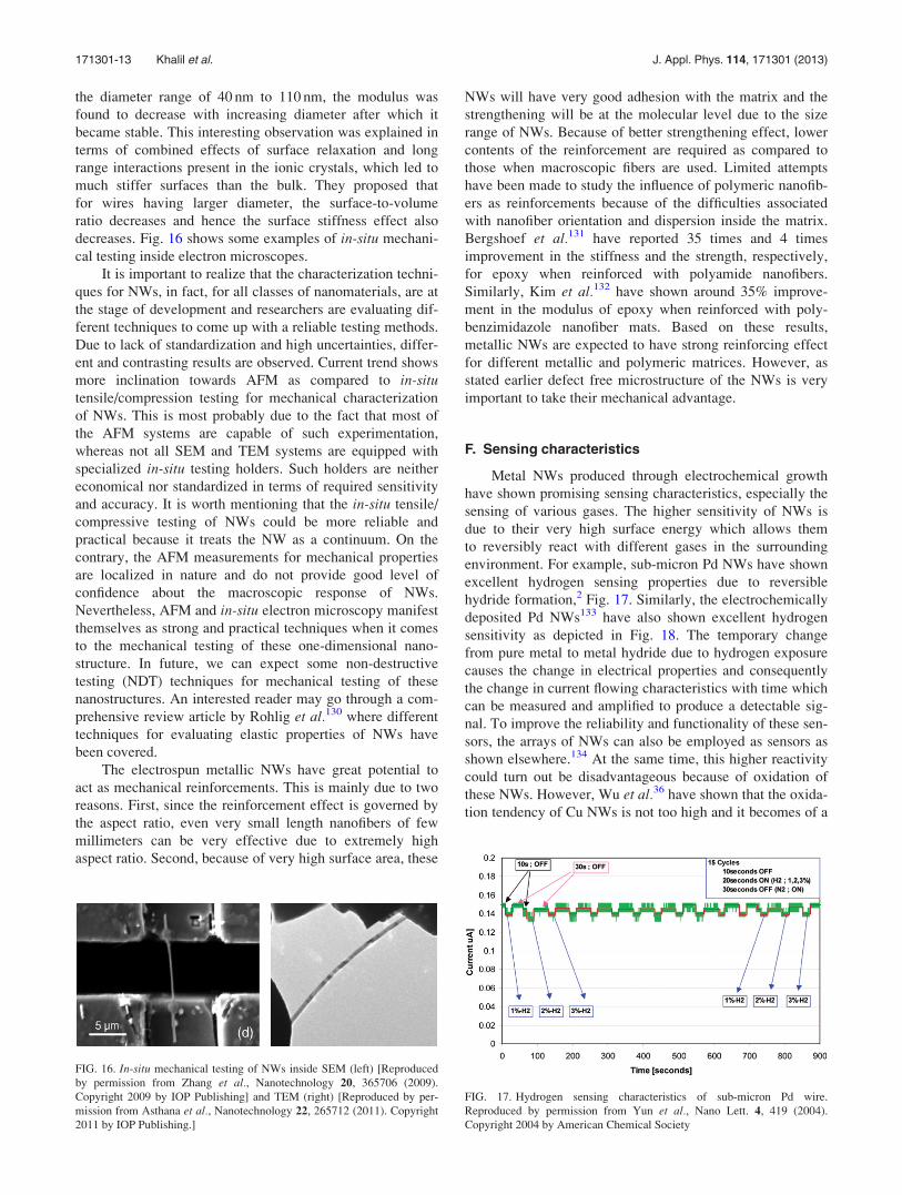
F. Sensing characteristics
Metal NWs produced through electrochemical growth
have shown promising sensing characteristics, especially the
sensing of various gases. The higher sensitivity of NWs is
due to their very high surface energy which allows them
to reversibly react with different gases in the surrounding
environment. For example, sub-micron Pd NWs have shown
excellent hydrogen sensing properties due to reversible
hydride formation,2 Fig. 17. Similarly, the electrochemically
deposited Pd NWs133 have also shown excellent hydrogen
sensitivity as depicted in Fig. 18. The temporary change
from pure metal to metal hydride due to hydrogen exposure
causes the change in electrical properties and consequently
the change in current flowing characteristics with time which
can be measured and amplified to produce a detectable sig-
nal. To improve the reliability and functionality of these sen-
sors, the arrays of NWs can also be employed as sensors as
shown elsewhere.134 At the same time, this higher reactivity
could turn out be disadvantageous because of oxidation of
these NWs. However, Wu et al.36 have shown that the oxida-
tion tendency of Cu NWs is not too high and it becomes of a
FIG. 16. In-situ mechanical testing of NWs inside SEM (left) [Reproduced
by permission from Zhang et al., Nanotechnology 20, 365706 (2009).
Copyright 2009 by IOP Publishing] and TEM (right) [Reproduced by per-
mission from Asthana et al., Nanotechnology 22, 265712 (2011). Copyright
2011 by IOP Publishing.]
FIG. 17. Hydrogen sensing characteristics of sub-micron Pd wire.
Reproduced by permission from Yun et al., Nano Lett. 4, 419 (2004).
Copyright 2004 by American Chemical Society
171301-13 Khalil et al. J. Appl. Phys. 114, 171301 (2013)

lesser concern if the NWs are to be used in the applications
where they are embedded underneath the other material. In
addition to gas sensors, the Mo NWs containing the beads of
other metallic nanoparticles, such as gold, have also been
proposed as very effective bio-sensors.135 Depending upon
the surface chemistry of nanoparticle, the specific nano/bio
species present in the environment may interact with it caus-
ing an overall change in the current carrying capacity of the
NW. This concept is depicted in Fig. 19. The high surface
energy and hence chemical reactivity/affinity is therefore
one of the key characters of metal NW which makes them
strong candidate for future sensors and related micro/nano
devices. Moreover, the variety of electrospun metal NWs
with different diameters and morphology will further lead to
cost reduction and mass production of such sensors.
Following the same approach for obtaining aligned electro-
spun metal NWs across two electrodes,90 the arrays of NW
acting as sensors can be obtained. The challenge however
remains that how these electrospun NWs can be integrated
with other micro/nano devices so that low cost and reliable
sensors may be developed.
G. Catalysts
Due to very high surface area, electrospun metal NWs
act as strong and active catalytic elements as shown in some
studies. Kim et al.38,39 have shown that electrospun Pt NWs
have much higher catalytic performance as compared to the
nanoparticles, as shown in Fig. 20. They explained this
behavior in terms of better electron transport in NWs due to
less collision across interfaces. Such NWs could thus serve
as efficient electrode materials for low temperature fuel cells.
Kim et al.40 have also shown that the rough surface and the
defective structure of electrospun Pt NWs can be advanta-
geous for better catalysis. The rough surfaces in these NWs
serve as active sites for effective electron transport and hence
enhance the catalytic activity. Based on these observations,
metal NWs seem to have important future applications as
electrodes in low cost fuel cells as well as in several chemi-
cal and electrochemical catalytic applications.
V. OUTLOOK
Despite several challenges, electrospinning manifests
itself as the most economical method for mass production of
metallic NWs. Moreover, providing excellent control over
final NW structure and properties is one of the key benefits
of this process over other methods. However, there is a
strong need to develop three clear connections in this regard.
First, the connection between the precursor properties and
the structure of NWs. Second, the connection between
the electrospinning parameters and the structure of NWs.
Finally, the connection between the structure and the differ-
ent properties of the NWs. Once these connections are well
developed and understood, the process can be commercial-
ized for mass production of metallic NWs for desired appli-
cations. At the same time, focus is needed to optimize the
electrospinning process for obtaining highest quality NWs
and to carefully understand their nanoscale response from
various perspectives. Also, the means to integrate the elec-
trospun metallic NWs with other materials and devices need
FIG. 18. Hydrogen sensing characteristics of a Pd NW. Reproduced by
permission from Walter et al., Microelectron. Eng. 61–62, 555 (2002).
Copyright 2002 by Elsevier BV.
FIG. 19. Schematic diagram of a beaded NW-based sensor. Depending on
the chosen metal and/or the presence of recognition elements, the interaction
of a specific molecule with the surface of the particle induces a conductivity
change. Reproduced by permission from Walter et al., Surf. Interface Anal.
34, 409 (2002). Copyright 2002 by John Wiley & Sons Ltd.
FIG. 20. Maximum power density for a given current in case of Pt NWs and
the Pt nanoparticles Reproduced by permission from Kim et al., Electrochem.
Commun. 11, 446 (2009). Copyright 2009 by Elsevier, Inc.
171301-14 Khalil et al. J. Appl. Phys. 114, 171301 (2013)

to be explored. This will pave the way towards the successful
and large scale usage of these electrospun metallic NWs in
future engineering applications. Advancements and innova-
tions in electrospun metal NWs can be foreseen at this stage.
For example, by using a combination of different metallic
salts, bimetallic or alloyed NWs can be produced. An exam-
ple of this approach has been demonstrated by Kim et al.136
for obtaining electrospun PtRh and PtRu NWs. In future,
we can expect electrospun metallic core shell NWs (nano-
pipes) and porous metallic NWs (nanofoams) via similar
approaches which have already been used for producing
core shell and porous polymeric nanofibers. Such metallic
NWs with customized morphology will open new doors of
research in the area of nanomaterials.
1“High-Level Expert Group On Key Enabling Technologies-Final
Report,” European Commission, 2011.2M. Yun, N. V. Myung, R. P. Vasquez, C. Lee, E. Menke, and R. M.
Penner, Nano Lett. 4, 419 (2004).3G. S. Lotey, S. Kumar, and N. K. Verma, Appl. Nanosci. 2, 7 (2012).4B. Maria, E. Toimil, V. Buschmann, D. Dobrev, R. Neumann, R. Scholz,
I. U. Schuchert, and J. Vetter, Adv. Mater. 13(1), 62–65 (2001).5T. Gao, G. Meng, Y. Wang, S. Sun, and L. Zhang, J. Phys.: Condens.
Matter 14, 355 (2002).6Y. T. Pang, G. W. Meng, Y. Zhang, Q. Fang, and L. D. Zhang, Appl.
Phys. A: Mater. Sci. Process. 76, 533 (2003).7L. Liu, S. Xie, L. Song, Y. Gao, D. Liu, X. Dou, S. Luo, J. Wang, X. Zhao,
Z. Zhang, Y. Xiang, W. Zhou, C. Wang, and G. Wang, Nanotechnology
17, 19 (2006).8R. P. Chauhan and D. Gehlawat, Sci. Adv. Mater. 4, 151 (2012).9Y.-J. Chen, J.-H. Hsu, and H.-N. Lin, Nanotechnology 16, 1112 (2005).
10Y. Ekinci, H. H. Solak, C. David, and H. Sigg, Opt. Express 14, 2323
(2006).11L. Chen, J. J. Wang, F. Walters, X. Deng, M. Buonanno, S. Tai, and
X. Liu, Appl. Phys. Lett. 90, 063111 (2007).12M. Geissler, H. Wolf, R. Stutz, E. Delamarche, U.-W. Grummt, B.
Michel, and A. Bietsch, Langmuir 19, 6301 (2003).13J. J. Wang, F. Walters, X. Liu, P. Sciortino, and X. Deng, Appl. Phys.
Lett. 90, 061104 (2007).14J.-H. Lee, K. Yang, S.-H. Hong, H. Lee, and K.-W. Choi, Microelectron.
Eng. 85, 710 (2008).15Z. Zhang, D. a Blom, Z. Gai, J. R. Thompson, J. Shen, and S. Dai, J. Am.
Chem. Soc. 125, 7528 (2003).16J.-Y. Lee, S. T. Connor, Y. Cui, and P. Peumans, Nano Lett. 8, 689
(2008).17S. Liu, J. Yue, and A. Gedanken, Adv. Mater. 13, 656 (2001).18Y. Sun, B. Gates, B. Mayers, and Y. Xia, Nano Lett. 2, 165 (2002).19Z. L. Wang, X. Y. Kong, X. Wen, and S. Yang, J. Phys. Chem. B 107,
8275 (2003).20Z. Liu, Y. Yang, J. Liang, Z. Hu, S. Li, S. Peng, and Y. Qian, J. Phys.
Chem. B 107, 12658 (2003).21Y. Chang, M. L. Lye, and H. C. Zeng, Langmuir 21, 3746 (2005).22C. F. Monson and A. T. Woolley, Nano Lett. 3, 359 (2003).23Y. Konishi, M. Motoyama, H. Matsushima, Y. Fukunaka, R. Ishii, and
Y. Ito, J. Electroanal. Chem. 559, 149 (2003).24S. K. Lim, M. J. Tambe, M. M. Brewster, and S. Gradecak, Nano Lett. 8,
1386 (2008).25H. Choi and S.-H. Park, J. Am. Chem. Soc. 126, 6248 (2004).26Y. Zhou, S. H. Yu, X. P. Cui, C. Y. Wang, and Z. Y. Chen, Chem. Mater.
11, 545 (1999).27R. Adelung, L. Kipp, J. Brandt, L. Tarcak, M. Traving, C. Kreis, and
M. Skibowski, Appl. Phys. Lett. 74, 3053 (1999).28R. Adelung, J. Brandt, K. Rossnagel, O. Seifarth, L. Kipp, M. Skibowski,
C. Ram�ırez, T. Strasser, and W. Schattke, Phys. Rev. Lett. 86, 1303
(2001).29R. Adelung, J. Brandt, L. Kipp, and M. Skibowski, Phys. Rev. B 63,
165327 (2001).30Y. Kondo and K. Takayanagi, Phys. Rev. Lett. 79, 3455 (1997).31W. Sigmund, J. Yuh, H. Park, V. Maneeratana, G. Pyrgiotakis, A. Daga,
J. Taylor, and J. C. Nino, J. Am. Ceram. Soc. 89, 395 (2006).
32M. Graeser, M. Bognitzki, W. Massa, C. Pietzonka, A. Greiner, and J. H.
Wendorff, Adv. Mater. 19, 4244 (2007).33M. Bognitzki, M. Becker, M. Graeser, W. Massa, J. H. Wendorff,
A. Schaper, D. Weber, A. Beyer, A. G€olzh€auser, and A. Greiner, Adv.
Mater. 18, 2384 (2006).34H. Wu, R. Zhang, X. Liu, D. Lin, and W. Pan, Chem. Mater. 19, 3506
(2007).35N. A. M. Barakat, B. Kim, and H. Y. Kim, J. Phys. Chem. C 113, 531
(2009).36H. Wu, L. Hu, M. W. Rowell, D. Kong, J. J. Cha, J. R. McDonough, J.
Zhu, Y. Yang, M. D. McGehee, and Y. Cui, Nano Lett. 10, 4242
(2010).37N. S. Hansen, D. Cho, and Y. L. Joo, Small 8, 1510 (2012).38H. J. Kim, Y. S. Kim, M. H. Seo, S. M. Choi, and W. B. Kim,
Electrochem. Commun. 11, 446 (2009).39Y. S. Kim, H. J. Kim, and W. B. Kim, Electrochem. Commun. 11, 1026
(2009).40J. M. Kim, H.-I. Joh, S. M. Jo, D. J. Ahn, H. Y. Ha, S.-A. Hong, and S.-K.
Kim, Electrochim. Acta 55, 4827 (2010).41A. Formhals, US patent 1,975,504 (1934).42W. J. Morton, US patent 705,691 (1902).43D. Li and Y. Xia, Adv. Mater. 16, 1151 (2004).44G. Taylor, Proc. R. Soc. London, Ser. A 313, 453 (1969).45A. L. Yarin, S. Koombhongse, and D. H. Reneker, J. Appl. Phys. 90,
4836 (2001).46J. Deitzel, J. Kleinmeyer, D. Harris, and N. Beck Tan, Polymer 42, 261
(2001).47T. Han, A. L. Yarin, and D. H. Reneker, Polymer 49, 1651 (2008).48P. K. Baumgarten, J. Colloid Interface Sci. 36, 71 (1971).49L. Larrondo and R. S. J. Manley, J. Polym. Sci.: Polym. Phys. Ed. 19, 909
(1981).50L. Larrondo and R. S. J. Manley, J. Polym. Sci.: Polym. Phys. Ed. 19, 921
(1981).51I. Hayati, A. I. Bailey, and T. F. Tadros, J. Colloid Interface Sci. 117, 205
(1987).52J. Doshi and D. H. Reneker, J. Electrost. 35, 151 (1995).53S. Megelski, J. S. Stephens, D. B. Chase, and J. F. Rabolt,
Macromolecules 35, 8456 (2002).54C. L. Casper, J. S. Stephens, N. G. Tassi, D. B. Chase, and J. F. Rabolt,
Macromolecules 37, 573 (2004).55D. H. Reneker and I. Chun, Nanotechnology 7, 216 (1996).56T. Subbiah, G. S. Bhat, R. W. Tock, S. Parameswaran, and S. S.
Ramkumar, J. Appl. Polym. Sci. 96, 557 (2005).57A. Greiner and J. H. Wendorff, Angew. Chem., Int. Ed. 46, 5670
(2007).58N. Tomczak, S. Gu, M. Han, N. F. van Hulst, and G. Julius Vancso, Eur.
Polym. J. 42, 2205 (2006).59P. W. Gibson, H. L. Schreuder-Gibson, and D. Rivin, AIChE J. 45, 190
(1999).60B. S. Lalia, Y. A. Samad, and R. Hashaikeh, J. Appl. Polym. Sci. 126,
E442 (2012).61B. S. Lalia, E. Guillen, H. Arafat, and R. Hashaikeh, J. Membr. Sci. 428,
104 (2013).62J. Zeng, X. Xu, X. Chen, Q. Liang, X. Bian, L. Yang, and X. Jing,
J. Controlled Release 92, 227 (2003).63H.-J. Jin, J. Chen, V. Karageorgiou, G. H. Altman, and D. L. Kaplan,
Biomaterials 25, 1039 (2004).64G. Larsen, R. Velarde-Ortiz, K. Minchow, A. Barrero, and I. G.
Loscertales, J. Am. Chem. Soc. 125, 1154 (2003).65S.-S. Choi, S. G. Lee, S. S. Im, S. H. Kim, and Y. L. Joo, J. Mater. Sci.
Lett. 22, 891 (2003).66Y. Wang and J. J. Santiago-Avil�es, Nanotechnology 15, 32 (2004).67J. J. Santiago-Aviles, Y. Wang, R. Furlan, and I. Ramos, Appl. Phys. A:
Mater. Sci. Process. 78, 1043 (2004).68D. Li and Y. Xia, Nano Lett. 3, 555 (2003).69D. Li, T. Herricks, and Y. Xia, Appl. Phys. Lett. 83, 4586 (2003).70P. Viswanathamurthi, N. Bhattarai, H. Y. Kim, D. R. Lee, S. R. Kim, and
M. A. Morris, Chem. Phys. Lett. 374, 79 (2003).71X. Yang, C. Shao, H. Guan, X. Li, and J. Gong, Inorg. Chem. Commun.
7, 176 (2004).72H. Guan, C. Shao, B. Chen, J. Gong, and X. Yang, Inorg. Chem.
Commun. 6, 1409 (2003).73H. Guan, C. Shao, S. Wen, B. Chen, J. Gong, and X. Yang, Inorg. Chem.
Commun. 6, 1302 (2003).
171301-15 Khalil et al. J. Appl. Phys. 114, 171301 (2013)

74N. Dharmaraj, H. C. Park, B. M. Lee, P. Viswanathamurthi, H. Y. Kim,
and D. R. Lee, Inorg. Chem. Commun. 7, 431 (2004).75R. Ramaseshan, S. Sundarrajan, R. Jose, and S. Ramakrishna, J. Appl.
Phys. 102, 111101 (2007).76S. Fridrikh, J. Yu, M. Brenner, and G. Rutledge, Phys. Rev. Lett. 90,
144502 (2003).77P. Viswanathamurthi, N. Bhattarai, H. Y. Kim, D. R. Lee, S. R. Kim, and
M. A. Morris, Chem. Phys. Lett. 374, 79 (2003).78J. T. McCann, D. Li, and Y. Xia, J. Mater. Chem. 15, 735 (2005).79J. Yuh, J. C. Nino, and W. M. Sigmund, Mater. Lett. 59, 3645 (2005).80S. Patachia, M. Rinja, and L. Isac, Rom. J. Phys. 51, 253 (2006).81G. Tillet, B. Boutevin, and B. Ameduri, Prog. Polym. Sci. 36, 191 (2011).82S. Choi, S. G. Lee, S. S. Im, S. H. Kim, and Y. L. Joo, J. Mater. Sci. Lett.
22, 891 (2003).83A. L. Yarin, S. Koombhongse, and D. H. Reneker, J. Appl. Phys. 89,
3018 (2001).84M. M. Hohman, M. Shin, G. Rutledge, and M. P. Brenner, Phys. Fluids
13, 2201 (2001).85Y. M. Shin, M. M. Hohman, M. P. Brenner, and G. C. Rutledge, Appl.
Phys. Lett. 78, 1149 (2001).86Y. J. Kim, Ph.D. thesis, University of Washington, 2011.87C. P. Carroll and Y. L. Joo, J. Non-Newtonian Fluid Mech. 153, 130 (2008).88E.-R. Kenawy, G. L. Bowlin, K. Mansfield, J. Layman, D. G. Simpson,
E. H. Sanders, and G. E. Wnek, J. Controlled Release 81, 57 (2002).89J. Kameoka and H. G. Craighead, Appl. Phys. Lett. 83, 371 (2003).90D. Li, Y. Wang, and Y. Xia, Nano Lett. 3, 1167 (2003).91D. D. Evanoff and G. Chumanov, J. Phys. Chem. B 108, 13948 (2004).92R. Hashaikeh, I. S. Butler, and J. A. Kozinski, Thin Solid Films 515,
1918 (2006).93D. M. Littrell, J. Vac. Sci. Technol. A 4, 1608 (1986).94D. M. Littrell, D. H. Bowers, and B. J. Tatarchuk, J. Chem. Soc., Faraday
Trans. 1 83, 3271 (1987).95P. J. Soininen, Z. K.-E. Elers, V. Saanila, S. Kaipio, T. Sajavaara, and
S. Haukka, J. Electrochem. Soc. 152, G122 (2005).96A. M. Abdelkader, A. Daher, R. A. Abdelkareem, and E. El-Kashif,
Metall. Mater. Trans. B 38, 35 (2007).97W.-K. Han, J.-W. Choi, G.-H. Hwang, S.-J. Hong, J.-S. Lee, and S.-G.
Kang, Appl. Surf. Sci. 252, 2832 (2006).98M. Graeser, M. Bognitzki, W. Massa, C. Pietzonka, A. Greiner, and J. H.
Wendorff, Adv. Mater. 19, 4244 (2007).99D. C. Bell, Y. Wu, C. J. Barrelet, S. Gradecak, J. Xiang, B. P. Timko, and
C. M. Lieber, Microsc. Res. Tech. 64, 373 (2004).100R. D. Tarey, R. S. Rastogi, and K. L. Chopra, Rigaku J. 4, 11 (1987).101P. Dutta, Spec. Sect., Current Sci. 78, 1478 (2000).102K. Ozalas and B. F. Hajek, Clays Clay Miner. 44, 811 (1996).103L. C. Campos, S. H. Dalal, D. L. Baptista, R. Magalha~es-Paniago, A. S.
Ferlauto, W. I. Milne, L. O. Ladeira, and R. G. Lacerda, Appl. Phys. Lett.
90, 181929 (2007).104F. Yang, S. Kung, M. Cheng, J. C. Hemminger, and R. M. Penner, ACS
Nano 4, 5233 (2010).105D. Li and Y. Xia, Nano Lett. 3, 555 (2003).106M. Wang, H. Singh, T. A. Hatton, and G. C. Rutledge, Polymer 45, 5505
(2004).
107J. W. Gilmanl, D. L. VanderHart, and T. Kashiwagi, Fire and PolymersII, ACS Symposium Series 599 (American Chemical Society, 1994).
108G. H. Michler, Electron Microscopy of Polymers (Springer, 2008).109R. Garcia and R. Perez, Surf. Sci. Rep. 47, 197 (2002).110A. Tilke, F. Simmel, H. Lorenz, R. Blick, and J. Kotthaus, Phys. Rev. B
68, 075311 (2003).111D. Sun, C. Chang, S. Li, and L. Lin, Nano Lett. 6, 839 (2006).112D. Li, Y. Wu, P. Kim, L. Shi, P. Yang, and A. Majumdar, Appl. Phys.
Lett. 83, 2934 (2003).113F. Zhou, A. Moore, J. Bolinsson, A. Persson, L. Fr€oberg, M. Pettes,
H. Kong, L. Rabenberg, P. Caroff, D. Stewart, N. Mingo, K. Dick,
L. Samuelson, H. Linke, and L. Shi, Phys. Rev. B 83, 205416 (2011).114Y. A. Kosevich and A. V. Savin, Europhysics Lett. 88, 14002 (2009).115P. Naphon and O. Khonseur, Int. Commun. Heat Mass Transfer 36, 39
(2009).116P. Zhou, C. Wu, and X. Li, Meas. Sci. Technol. 19, 115703 (2008).117L. M. Bellan, J. Kameoka, and H. G. Craighead, Nanotechnology 16,
1095 (2005).118S.-H. Lee, C. Tekmen, and W. M. Sigmund, Mater. Sci. Eng., A 398, 77
(2005).119S.-Y. Gu, Q.-L. Wu, J. Ren, and G. J. Vancso, Macromol. Rapid
Commun. 26, 716 (2005).120F. Ko, Y. Gogotsi, A. Ali, N. Naguib, H. Ye, G. L. Yang, C. Li, and
P. Willis, Adv. Mater. 15, 1161 (2003).121B. Kracke and B. Damaschke, Appl. Phys. Lett. 77, 361 (2000).122Y. Lu, C. Peng, Y. Ganesan, J. Y. Huang, and J. Lou, Nanotechnology
22, 355702 (2011).123H. Zheng, A. Cao, C. R. Weinberger, J. Y. Huang, K. Du, J. Wang, Y.
Ma, Y. Xia, and S. X. Mao, Nat. Commun. 1, 144 (2010).124Y. Lu, J. Song, J. Y. Huang, and J. Lou, Adv. Funct. Mater. 21, 3982
(2011).125M. S. Wang, I. Kaplan-Ashiri, X. L. Wei, R. Rosentsveig, H. D. Wagner,
R. Tenne, and L. M. Peng, Nano Res. 1, 22 (2008).126D. Zhang, J.-M. Breguet, R. Clavel, L. Phillippe, I. Utke, and J. Michler,
Nanotechnology 20, 365706 (2009).127A. Asthana, K. Momeni, A. Prasad, Y. K. Yap, and R. S. Yassar,
Nanotechnology 22, 265712 (2011).128H. Zheng, A. Cao, C. R. Weinberger, J. Y. Huang, K. Du, J. Wang, Y.
Ma, Y. Xia, and S. X. Mao, Nat. Commun. 1, 144 (2010).129Y. Lu, C. Peng, Y. Ganesan, J. Y. Huang, and J. Lou, Nanotechnology
22, 355702 (2011).130C.-C. R€ohlig, M. Niebelsch€utz, K. Brueckner, K. Tonisch, O. Ambacher,
and V. Cimalla, Phys. Status Solidi B 247, 2557 (2010).131M. M. Bergshoef and G. J. Vancso, Adv. Mater. 11, 1362 (1999).132J. K. I. M and D. H. Reneker, Polym. Compos. 20, 124 (1999).133E. C. Walter, K. Ng, M. P. Zach, R. M. Penner, and F. Favier,
Microelectron. Eng. 61–62, 555 (2002).134E. C. Walter, M. P. Zach, F. Favier, B. J. Murray, K. Inazu, J. C.
Hemminger, and R. M. Penner, Chemphyschem 4, 131 (2003).135E. C. Walter, R. M. Penner, H. Liu, K. H. Ng, M. P. Zach, and F. Favier,
Surf. Interface Anal. 34, 409 (2002).136Y. S. Kim, S. H. Nam, H.-S. Shim, H.-J. Ahn, M. Anand, and W. B. Kim,
Electrochem. Commun. 10, 1016 (2008).
171301-16 Khalil et al. J. Appl. Phys. 114, 171301 (2013)


