REVIEW OF RESEARCH OUTCOMES IN MILLIMETER WAVE...
21
38 CHAPTER 3 REVIEW OF RESEARCH OUTCOMES IN MILLIMETER WAVE MIMO
Transcript of REVIEW OF RESEARCH OUTCOMES IN MILLIMETER WAVE...
38
CHAPTER 3
REVIEW OF RESEARCH OUTCOMES IN MILLIMETER
WAVE MIMO

39
CHAPTER 3
REVIEW OF RESEARCH OUTCOMES IN MILLIMETER
WAVE MIMO
The advantage of MIMO is twofold link reliability and high data rate. These features when
combined with MMW address the problem of penetration losses and multipath fading.
Spatial diversity in transmitter and receiver is feasible in MMW as the size of the antenna is
of the order of millimeter. This is not the case for low frequency where diversity is exploited
only in fixed base station and not in the subscriber unit (SU). The reason being large sized
multi-antenna in the SU affects portability of the device. The data rate of the order of gigabits
per second is achieved owing to the unlicensed bandwidth and combining spatial
multiplexing with MMW. This chapter deals with survey of reported results of MMW
MIMO. The chapter is organized as follows: section 3.1 presents the MMW features and
challenges, section 3.2 presents MMW MIMO, section 3.3 discusses the need for
beamforming for 60 GHz system, section 3.4 presents the need for multibeam in MIMO,
section 3.5 presents the 60 GHz channel sounder and section 3.6 presents the research
outcomes in outdoor MMW MIMO.
3.1 Millimeter Wave features favoring use of MIMO
The major features in brief and technical challenges in MMW that necessitate the need for
MIMO is presented in the following section. The indoor channel in 57-64 GHz band
experiences oxygen absorption at 60 GHz and also high free space path loss. The oxygen
absorption limits the range to 10m indoor and 100m outdoor and this facilitates frequency
reuse with interference free operation between the MMW systems. The propagation loss is
overcome using high gain directional antenna. The directivity of an antenna scales inversely
as the square of carrier wavelength. As a result of these directive antennae, the multipath
environment is much sparser compared to lower carrier frequencies. Analysis of directional
transmission and reception with electronically steerable beams using compact antenna arrays
resulted in the compensation of propagation loss. Due to this, rich scattering environment
was then reduced to sparse scattering leading to moderate antenna separation. This has led to
40
achieve spatial multiplexing in LOS. Capacity computations indicate data rate of gigabits is
possible using channel bandwidths of the order of GHz (Torkildson, E. et al., 2010).
Indoor channel model
The channel model for WPAN is different from that of WLAN as the distance ranges are
smaller, influence of human presence close to antenna device. These characteristics motivate
the need for generalizing classical LOS MIMO model based on the assumption that antenna
channel experience different small scale statistics and different channel gain. Hence MIMO
channel model for WPAN is proposed and the simulation results on capacity, eigenvalue
distribution and antenna correlation validated with measured data (Karedal, J. et al., 2010).
License free huge bandwidth
Making effective use of the unlicensed bandwidth, Ariza,A.P.G., proposed a method for high
data rate polarimetric radio wave processing that finds use in short range communications
and radar (Ariza, A.P.G., 2013). Tap-wise polarimetric filtering in delay domain enhances
the 60 GHz link budget. This filtering enhances multipath from scatterers around the link and
reduces multipath due to shadowing. In addition to this, MIMO polarimetry reduces heavy
clutter for MMW radar. This help in capturing the complete information of the target and
clutter (Ariza, A.P.G., 2013).
Small Scale fading effects
Small scale fading accounting for multipath effects dominates the signal propagation in
indoor environment. MIMO small scale fading channel parameters in an underground gold
mine analyzed by Mabrouk,I.B et al., in two scenarios, one in physically static environment
and other in the presence of miners (Mabrouk, I.B. et al., 2013). As the propagation loss at 60
GHz is high, 2x2 MIMO antenna based on microstrip patch array was designed and
fabricated. Using this experimental setup, various parameters like RMS delay spread, path
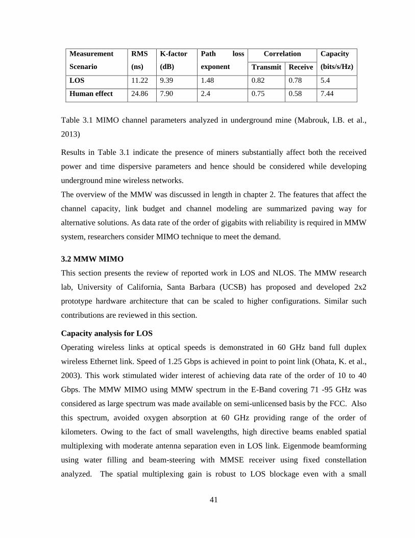
loss, K-factor, channel correlation and capacity were analyzed. Table 3.1 shows the results
(Mabrouk, I.B. et al., 2013).
41
Measurement
Scenario
RMS
(ns)
K-factor
(dB)
Path loss
exponent
Correlation Capacity
(bits/s/Hz) Transmit Receive
LOS 11.22 9.39 1.48 0.82 0.78 5.4
Human effect 24.86 7.90 2.4 0.75 0.58 7.44
Table 3.1 MIMO channel parameters analyzed in underground mine (Mabrouk, I.B. et al.,
2013)
Results in Table 3.1 indicate the presence of miners substantially affect both the received
power and time dispersive parameters and hence should be considered while developing
underground mine wireless networks.
The overview of the MMW was discussed in length in chapter 2. The features that affect the
channel capacity, link budget and channel modeling are summarized paving way for
alternative solutions. As data rate of the order of gigabits with reliability is required in MMW
system, researchers consider MIMO technique to meet the demand.
3.2 MMW MIMO
This section presents the review of reported work in LOS and NLOS. The MMW research
lab, University of California, Santa Barbara (UCSB) has proposed and developed 2x2
prototype hardware architecture that can be scaled to higher configurations. Similar such
contributions are reviewed in this section.
Capacity analysis for LOS
Operating wireless links at optical speeds is demonstrated in 60 GHz band full duplex
wireless Ethernet link. Speed of 1.25 Gbps is achieved in point to point link (Ohata, K. et al.,
2003). This work stimulated wider interest of achieving data rate of the order of 10 to 40
Gbps. The MMW MIMO using MMW spectrum in the E-Band covering 71 -95 GHz was
considered as large spectrum was made available on semi-unlicensed basis by the FCC. Also
this spectrum, avoided oxygen absorption at 60 GHz providing range of the order of
kilometers. Owing to the fact of small wavelengths, high directive beams enabled spatial
multiplexing with moderate antenna separation even in LOS link. Eigenmode beamforming
using water filling and beam-steering with MMSE receiver using fixed constellation
analyzed. The spatial multiplexing gain is robust to LOS blockage even with a small

42
transmit power per antenna element achieved using low cost CMOS process (Torkildson, E.
et al., 2010). The authors extended the work using adaptive beamforming and spatial
multiplexing to obtain capacity improvement. Adaptive beamforming using adaptive
antenna array called subarray, enabled highly directive beam steerable over a larger angle
improving the directivity gain in both transmitter and receiver. Subarrays were interpreted as
single virtual elements in MIMO system with antenna spacing satisfying the Rayleigh
criterion for realizing uniform array. This characteristic claimed the possibility of attaining
high data rates of the order of 40 Gbps (Torkildson, E. et al., 2006). The concept extended to
analyzing MMW in 57-64 GHz band for indoor environment.
Authors (Torkildson E. et al., 2006) analyzed the performance fixing the range as 1km,
which might not hold good if the range varies. The performance degradation is attributed to
correlation between the spatial responses for different transmitters. Hence non-uniform
arrays were proposed that reduced correlation over large set of ranges (Torkildson, E. et al.,
2009).
Capacity of short range systems using channel transfer function with angle of arrival (AoA)
proposed. AoA data measured with the experimental setup used to calculate the 2x2 MIMO
static channel capacity for varying antenna spacing of 1 mm to 20mm and transmit and
receive distance of 27 cm (Liu, C. et al., 2010).
Hardware prototype
Hardware prototype demonstrating two channel spatial multiplexing operating at 1.2 Gbps in
indoor office environment developed (Sheldon,C. et al., 2008). This was tested in indoor with
6.14 m link range and 12.4cm antenna element separations. Diffraction limited optics was
used to establish multiple parallel data channels. This system can be scaled to longer link
range, larger one and two dimensional arrays supporting data rate greater than 160 Gbps
(Sheldon,C. et al., 2008).
Scalable architecture proposed for four channel spatial multiplexing in LOS link using 1x4
linear arrays in transmitter and receiver. The system was tested in indoor office environment
at 5m link range with antenna element spacing of 7.9cm. BER of less than 10-5
reported with
signal to interference ratio of 11 dB (Sheldon, C. et al., 2009). This replaces the manually
tuned channel separation at Intermediate Frequency (IF) reported in (Sheldon, C. et al., 2008)
with automatically tuned baseband channel separation. Enhancing the performance of
43
channel separation electronics in (Sheldon, C. et al., 2009) resulted in data rate of 2.4 Gbps
(Sheldon, C. et al., 2010).
Spatial degree of freedom
Spatial degree of freedom is limited by the antenna array geometry, number of antennas and
the scattering environment. Lower frequency systems rely on multipath for obtaining an
uncorrelated channel leading to high multiplexing gain. But MMW systems, experience high
propagation loss due to multipath that reduces the probability of uncorrelated channel. This is
overcome by placing antenna with moderate separation with spatial degree of freedom
preserved. Optimal array configuration has been analyzed such that LOS channel capacity is
maximum with minimum number of antenna elements (Torkildson, E. et al., 2009).
Capacity analysis for NLOS
Minimum antenna spacing effects on capacity were analyzed. Antenna spacing of the order
of the wavelength or fraction of wavelength was required for MIMO channels with both LOS
and reflected path while few tens of wavelength was required for MIMO channel with only
LOS. The reason attributed is LOS path suffers from blockages. Hence channel capacity of
MIMO channel with LOS and reflected path was higher compared to MIMO channel with
LOS (Lee, S.J. et al., 2010).
Capacity with multiple elements at both antenna terminals at 60 GHz was studied for SIMO,
MISO and MIMO configurations. The channel model utilized the geometric characteristics of
the environment, angle of arrival, angle of departure of the propagation paths, the antenna
elements and their spacing. Capacity of 4 bits/s/Hz was estimated for transmit and receive
distance of 15m (Arvanitis, A. et al., 2007).
Study of improving the directivity and spatial multiplexing gain in the presence of multipath
and LOS blockage led to the proposal of MMW MIMO architecture using array of subarrays
(Torkildson, E. et al., 2011). Ray tracing model was used to simulate the indoor environment.
Authors have compared the performance of the eigenmode transmission using waterfilling
power allocation with beamsteering transmission and MMSE reception for a fixed signal
constellation. The study provides insights of spatial variations of attainable capacity within a
room. Promising multiplexing gain achieved by electronic beam steering for each subarray
that makes the link robust to node placement and LOS blockage (Torkildson, E. et al., 2011).
44
3.3 Need for beamforming for 60 GHz system
MMW radio suffers severe path loss, oxygen absorption and limited link budget. Methods to
overcome the losses and improve link budget suggest using high gain directional antenna and
beamforming technique. Blockage by metal objects deters the use of high gain directional
antenna. Fixed and adaptive beamforming using MIMO antenna array form the best alternate
in diffraction limited environment. The analysis with the objective of improving the link
robustness, channel capacity, array gain, mixed beamforming techniques are discussed in
length in the following sections.
Beamforming analysis
The influence of beamforming in LOS and NLOS scenario analyzed based on narrowband
and wideband direction based beamformers for 5x5 and 7x7 planar array (Wyne, S. et al.,
2011). Narrowband beamformer operating on 200 MHz bandwidth and wideband
beamformer operating on 4 GHz full bandwidth were used to investigate in terms of
improving the channel metrics i.e. delay spread, excess delay and SNR. The direction based
beamformer was compared with various theoretical bounds. RMS delay spread and excess
delay in beamformed LOS channel was around 1 ns and 0.5 ns. The array gain or SNR
improvement was MN, with M and N representing the antenna elements in transmitter and
receiver. The performance of direction based beamformer LOS channel was comparable to
dominant eigenmode and statistical beamformer. Beamformed NLOS channel showed
performance degradation relative to dominant eigenmode (Wyne, S. et al., 2011). The
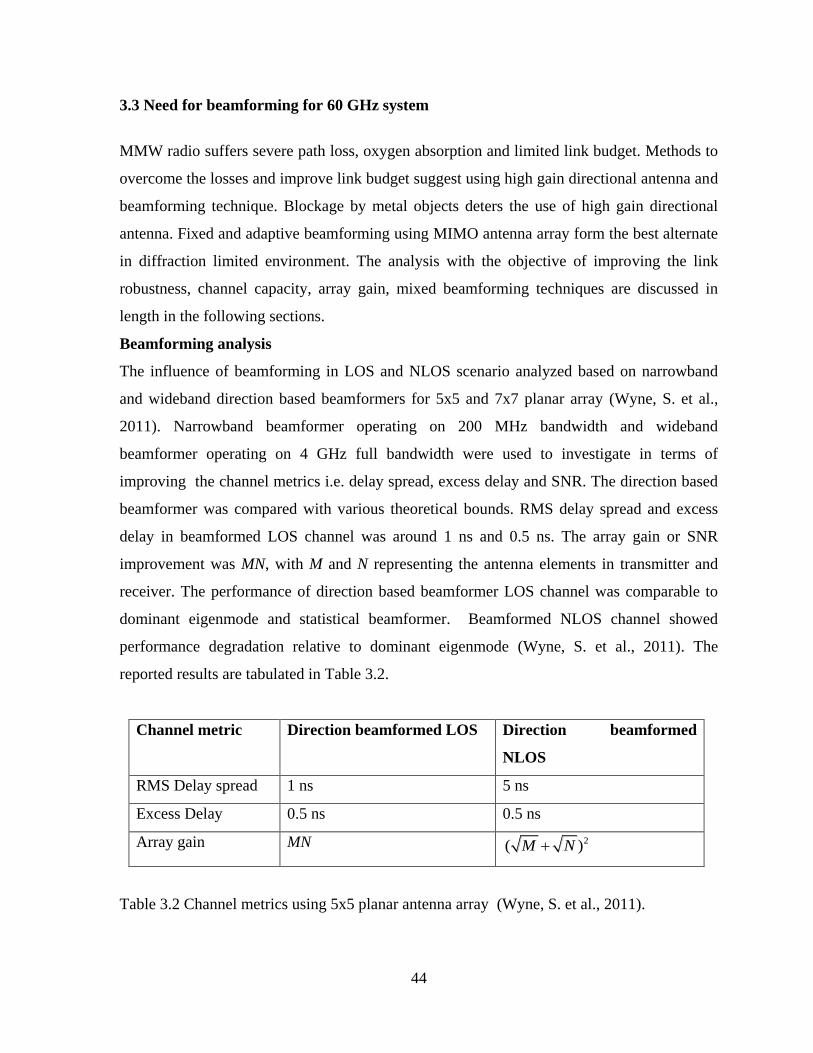
reported results are tabulated in Table 3.2.
Channel metric Direction beamformed LOS Direction beamformed
NLOS
RMS Delay spread 1 ns 5 ns
Excess Delay 0.5 ns 0.5 ns
Array gain MN 2( )M N
Table 3.2 Channel metrics using 5x5 planar antenna array (Wyne, S. et al., 2011).

45
Results in Table 3.2 indicate that the NLOS channels have few strong reflected components.
Also influence of array size on beamforming was analyzed in addition to the channel metric.
The 7x7 planar array had the same performance as the 5x5 array, thus setting limits for
practically realizable array size.
Weight vector for beamforming
Beamforming vectors using iterative antenna training algorithm proposed (Xia, P. et al.,
2008). This algorithm computes the Tx/Rx beamforming vector for both training and payload
phase with reduced training overhead and is found efficient compared to antenna training. In
antenna training entire channel co-efficients are estimated while in iterative algorithm two
matrices one each in transmit and receive side are updated based on previous beamforming
vectors (Xia, P. et al., 2008).
Conventional baseband beamforming depends on channel matrix and thereupon determining
the weight vectors with exact amplitude and phase. This method is quite impractical as it
requires multiple RF chains that lead to high power consumption and also increases the
complexity of the phase shifter and gain controller to cover a wider range of phases and
amplitudes. Hence to minimize power consumption of RF devices, codebook based
beamforming proposed (Wang, J. et al., 2009). The elements of the codebook are specified
by one of the four phase shifts (0, 90, 180 and 270 degrees) without any amplitude
adjustment.
Multilevel training and antenna selection was considered in order to reduce the beamforming
setup time (Lee, H-H. and Ko, Y-C. 2011). In every level transmit and receive antennas are
selected based on inter-element spacing. This is followed with transmitting training
sequences with different weight vectors from a pre-defined codebook. This helps the receiver
to select the best transmit and receive weight vector to optimize the SNR. These vectors
determine the codebook for the next level. This is computationally less complex relative to
conventional codebook based beamforming that uses an exhaustive search transmitting all
the training sequences before the best beam pair is selected (Lee, H-H. and Ko, Y-C. 2011).
Efficient codebook –based MIMO beamforming training scheme proposed for estimating
antenna weight vectors (Zhou, L. and Ohashi, Y. 2012). Initially Discrete Fourier Transform
(DFT) based codebook entries were used that had equal amplitude with low power
consumption. The training algorithm then selects the best transmit weight vector and receive
46
weight vector as compared with multiple selection of weight vector in IEEE 802.11ad.
Further refinement of weight vectors is performed by angular rotation around the best
transmit and receive weight vector to improve the beam gain. The proposed work
outperforms the IEEE 802.11ad standard in terms of efficient beamforming gain with less
setup time (Zhou, L. and Ohashi, Y. 2012).
Joint transmit and receive analog beamforming (ABF) proposed for systems with one scalar
weight per antenna (Nsenga, J. et al., 2009). This is aimed at realizing low cost, low power
MMW system. The scheme targets maximizing the average SNR at the input of the equalizer
and analytically derive the close to optimal transmit/receive (Tx/Rx) scalar weights. The joint
Tx/Rx ABF weights computed using channel state information (CSI). CSI is obtained from
the inner product between all Tx/Rx channel impulse response (CIR) pairs. The BER
performance of the joint Tx/Rx ABF outperforms the ABF scheme (Nsenga, J. et al., 2009).
Low cost multi-antenna architectures with a lower number of analog front end chains than
antenna elements proposed (Nsenga, J. et al., 2010). This enables mixed analog/digital
beamformers that aim at maximizing the received average SNR. The performance found to
be better than antenna selection techniques and digital beamforming (Nsenga, J. et al., 2010).
Beamforming and Precoding attempted with large antenna arrays. Precoding in traditional
MIMO systems is implemented in the baseband (Pi, Z. and Khan, F. 2011; Doan, C. et al.,
2004). Baseband processing requires a dedicated radio frequency (RF) chain. This increases
the cost of MMW RF hardware (Pi, Z. and Khan, F. 2011; Doan, C. et al., 2004). Thus
precoding is shared between the analog and digital domain. Precoding in analog domain is
done to reduce high cost of mixed -signal and RF chains. However precoding in the RF
domain after upconversion is implemented using analog phase shifters (Zhang, X. et al.,
2005; Nsenga, J. et al., 2010), that place a constant modulus constraint on the elements of
the precoding matrix. Antenna selection, equal gain transmissions were proposed to address
the problem of limited number of transmit/receive chains. These solutions do not account for
large MMW systems, where transmit correlation is to be analyzed. Single user beamforming
and precoding in MMW systems using large arrays is considered. The structure of MMW
channel was exploited to design the precoder using sparsity constrained least square method.
Principle of basis pursuit was used to develop the precoding algorithm that approximates
unconstrained precoder using low dimensional basis representation. This results in low
47
complex RF hardware and the capacity of proposed algorithm was equal to that of MMW
system using waterfilling method (Ayach, O.E. et al., 2012; Ayach, O.E. et al., 2012).
MIMO postamble, used to reduce the complexity of implementation in MIMO beamformed
system with SVD proposed (Tiraspolsky, S. et al., 2010). The complexity reduction is
achieved by extracting CSI from the MIMO postambles that avoids the need for feedback.
This leads to simple MIMO system architecture (Tiraspolsky, S. et al., 2010).
Conventional beamforming with open loop transmit diversity studied and performance
evaluated based on theoretical calculations. The hybrid scheme provides gain improvement
over conventional beamforming with the same complexity (Pedersen, K.I. and Mogensen,
P.E. 2001).
Beamforming and closed loop transmit diversity in downlink proposed (Goransson, B. et al.,
2004). The transmitted signal phase and amplitude on the diversity antennas is adjusted using
feedback from each mobile user. With fixed antenna array, energy is radiated in fixed
direction that may lead to interference to the mobile user other than the intended mobile user.
To meet the Quality of Service (QoS), high power overcoming the interference is required. In
an attempt to reduce the interference adaptive antenna array capable of steering the radiated
energy to or from the mobile user is used (Goransson, B. et al., 2004).
Near field beamforming addressing beampointing error is analyzed (Yan-ping, L. et al.,
2012). The problem is formulated for uniform linear array. Convex optimization is applied to
update the steering vector error of the beam, by maximizing the signal to interference and
noise ratio subject to the constraint of minimum output variance of the source signal (Yan-
ping, L. et al., 2012).
Continuous Aperture Phased (CAP) MIMO based on the concept of beamspace MIMO that
enables efficient access to the p communication modes of an n-dimensional MMW link is
proposed, where p << n (Song, G-H. et al., 2013; Brady, J. et al., 2013). This is possible by
exploiting the spatial dimension at MMW using high gain directional antenna proportional to
n that leads to sparsity of propagation paths. This reduces the dimension of the
communication subspace. Discrete lens array used to capture the beamspace channel matrix.
The channel matrix is nearly diagonal indicating orthogonal Fourier spatial basis vectors used
for beamforming. This is an indication of spatial multiplexing of data streams over p
dimensional communication subspace. Thus using CAP MIMO enables near-optimal
48
communication with reduction in transceiver complexity. Mutual coupling is a matter of
concern between closely spaced feed antennas which requires further investigation (Song, G-
H. et al., 2013; Brady, J. et al., 2013).
MIMO beamforming in multiuser environment
Opportunistic beamforming in the transmitter that induces random beamforming in the
network is reviewed. In order to have maximum opportunism, the system depends on perfect
CSI. The authors Ozdemir, O. and Torlak, M., at University of Texas, Dallas have
investigated the benefit of partial CSI at an opportunistic transmitter. The partial CSI
information was basically the signal to noise ratio (SNR) relative to channel gain feedback by
the user. The effect of relative SNR was then used to improve the throughput of the system
(Ozdemir, O. and Torlak, M., 2008). The authors have extended the work by developing an
optimum SNR quantization method that is performed at the mobile terminal. This
development is later used to analyze the system throughput. Furthermore, the analysis
indicates when the number of users in the system approach infinity, the performance of the
opportunistic beamforming approaches to that of true beamforming (Ozdemir, O. and Torlak,
M., 2010).
Optimum zero forcing downlink beamforming analysed. The scheduling of the multiuser
studied using greedy algorithm and water filling power allocation with average power
constraint at the transmitter. The authors have derived joint probability density function for
the scheduled users. The sum rate performance is evaluated and results indicate that the
subchannel gains of the previously scheduled users remain unaffected. This is due to the
cutoff value for water filling power allocation is suitably expressed (Ozyurt, S. and Torlak,
M. 2012). The authors have extended the analysis in evaluating the zero forcing (ZF) Vertical
Bell Labs Layered Space-Time (V-BLAST) algorithm using greedy decoder ordering in
Rayleigh fading channels. The joint probability density function (pdf) of the squared layer
gains assuming no error propagation is derived and is found applicable to any number of
transmit and receive antennas. Based on this, joint distribution of the ordered gains from the
joint distribution of the unordered gains is determined. This results in optimal power
allocation using water filling algorithm avoiding extensive simulations to be carried out
(Ozyurt, S. and Torlak, M. 2013).
49
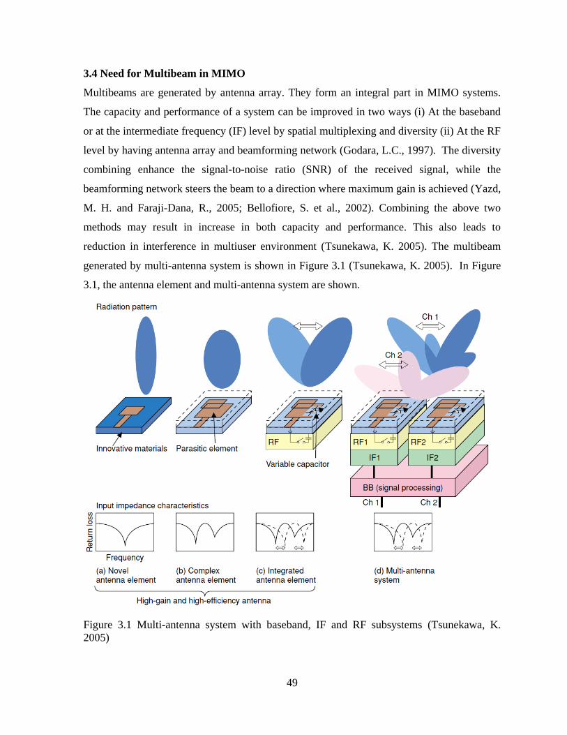
3.4 Need for Multibeam in MIMO
Multibeams are generated by antenna array. They form an integral part in MIMO systems.
The capacity and performance of a system can be improved in two ways (i) At the baseband
or at the intermediate frequency (IF) level by spatial multiplexing and diversity (ii) At the RF
level by having antenna array and beamforming network (Godara, L.C., 1997). The diversity
combining enhance the signal-to-noise ratio (SNR) of the received signal, while the
beamforming network steers the beam to a direction where maximum gain is achieved (Yazd,
M. H. and Faraji-Dana, R., 2005; Bellofiore, S. et al., 2002). Combining the above two
methods may result in increase in both capacity and performance. This also leads to
reduction in interference in multiuser environment (Tsunekawa, K. 2005). The multibeam
generated by multi-antenna system is shown in Figure 3.1 (Tsunekawa, K. 2005). In Figure
3.1, the antenna element and multi-antenna system are shown.
Figure 3.1 Multi-antenna system with baseband, IF and RF subsystems (Tsunekawa, K.
2005)
50
The baseband unit, RF and antenna element together form the multi-antenna system in Figure
3.1. High gain in antenna element is achieved by adding a parasitic element or integrating an
RF circuit. The radiation pattern is controlled by baseband signal processing and hence
pattern of each wireless channel can be controlled by each baseband channel. Thus, multi-
antenna systems are generally called smart or active antennas (Alexiou, A. and Haardt, M.
2004).
Multibeam selection scheme, selecting the best subset of all beams to maximize capacity
using orthonormal random beamforming with partial CSI is proposed (Zhang, K. and Niu, Z.
2006). The scheme is compared with dirty paper coding that uses full CSI and is found to
have performance improvement under low SNR (Zhang, K. and Niu, Z. 2006).
Diversity and Multiplexing gain for multi-user MIMO using orthogonal multiple random
beams proposed (Oho, D.-C. and Lee, Y.-H. 2005). Orthogonal beams enable users to
experience multiple channels at the same time realizing multi-user diversity. Also
multibeams increase the multiplexing gain. Both MISO and MIMO configuration benefit
from the scheme (Oho, D.-C. and Lee, Y.-H. 2005). Multibeam assisted MIMO (MBA-
MIMO) proposed as an alternative for fixed beamfomer that suffers from inter-beam
interference proposed (Papadogiannis, A. and Burr, A.G. 2011). MBA-MIMO is applied in
the beam domain to mitigate interference and enable the provision of required capacity
density (Papadogiannis, A. and Burr, A.G. 2011).
3.5 60 GHz channel sounder
Measurement of capacity and double directional parameters with 16 x16 MIMO systems was
performed in LOS, LOS obstructed and NLOS (Ranvier, S. et al., 2005; Foschini, J.G. 1996).
Direction of Arrival (DOA) and Direction of Departure (DOD) were calculated from LOS
measurements and channel capacity was calculated from NLOS. MIMO capacity obtained in
NLOS is less compared to i.i.d Rayleigh channel (Ranvier, S. et al., 2005; Foschini, J.G.
1996). 2x2 MIMO capacity measured using 4-port Agilent Network Analyzer. Open-ended
waveguide antennas with different orientations are used in the study. The study confirms the
achievement of enhanced data rate assessed using the Shannon capacity theorem (Ahmadi-
Shokouh, J. et al., 2012).

51
3.6 Outdoor MMW MIMO
Outdoor deployment of MMW was analyzed, investigating the robustness of the link using
ray tracing channel model (Zhang, H. et al., 2010). This study indicated the sensitivity of the
received power to small variations in propagation geometry, which has led the analysis to
employ multiple antennas. Robust performance was reported based on antenna separation,
transmit precoding and space time coding (Zhang, H. et al., 2010).
A two channel hardware prototype operating at 1.2 Gbps over a link range of 41m
highlighted the potential of spatial multiplexing in LOS link (Sheldon, C. et al., 2008). The
prototype achieved a BER of less than 2x10⁻⁶
and data rate of 600 Mbps per channel. The
antenna spacing as a function of wavelength and link range determined in interference
limited propagation (Sheldon, C. et al., 2008).
Multilevel beamforming in outdoor MMW communication systems using beam searching
algorithm and codebook design proposed (Hur, S. et al., 2011). The codebook controls the
beamwidth and steering direction. The study is used in the design of MMW backhaul
systems supporting picocell data traffic. The codebook is designed based on adaptive
beamwidth beamforming technique developed on subarray using squinting angles. As
beamwidth is inversely proportional to the array size (Trees, H.L.V. 2002), sharp beam is
obtained using the entire array, while this beam can be broadened using subarraying and
squinting. Each level of the codebook uses a different subarray size resulting in varied
beamwidth. Directional gain issue arising out of squinting and subarraying is avoided using
spectral windowing. The performance of the exhaustive search technique when compared
with proposed scheme offers better beamforming gain at the cost of increased complexity.
But the proposed joint search method displays larger gain compared to one-side search with
the same complexity (Hur, S. et al., 2011).

52
Summary of the comparative description of various reported results of MMW MIMO
worldwide.
a) Ariza,A.P.G., et al., (2013), IEEE Transactions on Antennas and Propagation.
(a)
b) Mabrouk,I.B. et al., (2013), IEEE Transactions on Antennas and Propagation
(b)
c) Song, G-H et al., (2013),International Conference on Acoustics, Speech and Signal
Processing
d) Brady, J. et al., (2013), IEEE Transactions on Antennas and Propagation
(c)
Parameter Methodology/Formulation Outcome
Multipath effects
resulting from
scatterer and
shadowing
Polarimetric radio wave processing.
Polarimetry is used to analyze the
characteristics of electromagnetic waves.
Tap-wise polarimetric filtering in delay
domain enhancing the 60 GHz link budget.
Enhanced multipath from
scatterers around the link
and reduces multipath due to
shadowing. In addition to
this, MIMO polarimetry is
proposed to reduce heavy
clutter for MMW radar.
Parameter Methodology/Formulation Outcome
MIMO channel
parameters in an
underground gold
mine (RMS delay
spread, K-factor,
path loss
exponent, Tx/Rx
correlation,
capacity)
2x2 MIMO antenna based microstrip
patch array designed.
Parameters were studied in two
scenarios: one in physically static
environment and other in the presence of
miners. Table 3.1 lists the measured data
for the above two cases.
The presence of miners
substantially affects both
received power and time
dispersion parameters and
the effects to be considered
when developing
underground mine wireless
networks in the unlicensed
60-GHz
band.
Parameter Methodology/Formulation Outcome
Channel matrix Continuous Aperture Phased (CAP)
MIMO based on the concept of
beamspace MIMO that enables efficient
access to the p communication modes of
an n-dimensional MMW link, where p
<< n.
Exploiting the spatial dimension at
MMW using high gain directional
antenna proportional to n that leads to
sparsity of propagation paths. This
reduces the dimension of the
communication subspace.
Channel matrix is nearly
diagonal indicating
orthogonal Fourier spatial
basis vectors used for
beamforming

53
e) Ozyurt, S. and Torlak, M. (2013), IEEE Transactions on Wireless Communications
(d)
f) Ayach, O.E. et al., (2012) IEEE International Conference on Communications.
g) Ayach,O.E. et al., (2012), IEEE International Workshop on Signal Processing Advances in
Wireless Communications.
(e)
h) Liu. C. et al., (2010), IEEE Transactions on Wireless Communications.
(f)
i) Ozdemir, O. and Torlak, M. (2010), IEEE Transactions on Wireless Communications
(g)
Parameter Methodology/Formulation Outcome
Sum rate and
Subchannel gain
Downlink Beamforming in multiuser
environment
Zero Forcing V-BLAST using greedy
decoder ordering in Rayleigh fading
channel.
The joint probability density
function assuming no error
propagation derived. This
results in optimal power
allocation using water filling
algorithm.
Parameter Methodology/Formulation Outcome
Channel capacity
and RF hardware
complexity
Beamforming and precoding in MMW
systems with large arrays.
Principle of basis pursuit was used to
develop the precoding algorithm that
approximates unconstrained precoder
using low dimensional basis
representation.
Capacity is equal to that
achieved using water filling
algorithm.
Parameter Methodology/Formulation Outcome
Channel Capacity
Angle-of-Arrival information used to
predict the
static channel capacity.
An Anritsu 37397 Vector Network
Analyzer (VNA) used to measure the
channel transfer function.
LOS
signal contributes
significantly to the spatial
MIMO channel
capacity for short distance
applications.
Parameter Methodology/Formulation Outcome
SNR and
Throughput
Optimum SNR quantization performed
at the mobile terminal
Opportunistic beamforming in the
transmitter for flat and slow fading
channel.
System throughput is
improved. The performance
of opportunistic
beamforming approaches
true beamforming when
number of users in the
system approach infinity.
54
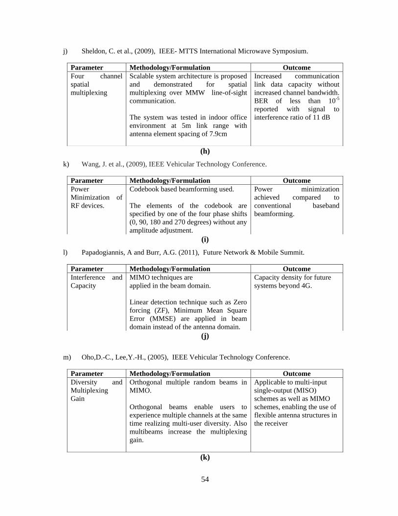
j) Sheldon, C. et al., (2009), IEEE- MTTS International Microwave Symposium.
(h)
k) Wang, J. et al., (2009), IEEE Vehicular Technology Conference.
(i)
l) Papadogiannis, A and Burr, A.G. (2011), Future Network & Mobile Summit.
(j)
m) Oho,D.-C., Lee,Y.-H., (2005), IEEE Vehicular Technology Conference.
(k)
Parameter Methodology/Formulation Outcome
Four channel
spatial
multiplexing
Scalable system architecture is proposed
and demonstrated for spatial
multiplexing over MMW line-of-sight
communication.
The system was tested in indoor office
environment at 5m link range with
antenna element spacing of 7.9cm
Increased communication
link data capacity without
increased channel bandwidth.
BER of less than 10-5
reported with signal to
interference ratio of 11 dB
Parameter Methodology/Formulation Outcome
Power
Minimization of
RF devices.
Codebook based beamforming used.
The elements of the codebook are
specified by one of the four phase shifts
(0, 90, 180 and 270 degrees) without any
amplitude adjustment.
Power minimization
achieved compared to
conventional baseband
beamforming.
Parameter Methodology/Formulation Outcome
Interference and
Capacity
MIMO techniques are
applied in the beam domain.
Linear detection technique such as Zero
forcing (ZF), Minimum Mean Square
Error (MMSE) are applied in beam
domain instead of the antenna domain.
Capacity density for future
systems beyond 4G.
Parameter Methodology/Formulation Outcome
Diversity and
Multiplexing
Gain
Orthogonal multiple random beams in
MIMO.
Orthogonal beams enable users to
experience multiple channels at the same
time realizing multi-user diversity. Also
multibeams increase the multiplexing
gain.
Applicable to multi-input
single-output (MISO)
schemes as well as MIMO
schemes, enabling the use of
flexible antenna structures in
the receiver
55
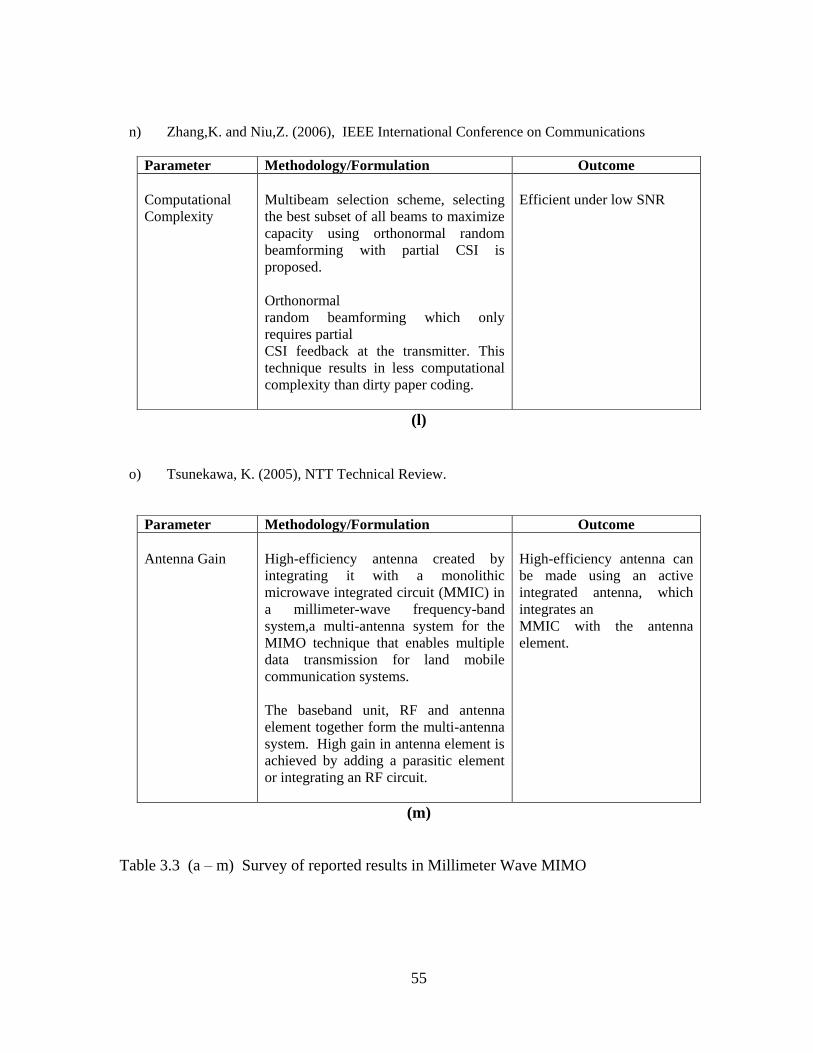
n) Zhang,K. and Niu,Z. (2006), IEEE International Conference on Communications
(l)
o) Tsunekawa, K. (2005), NTT Technical Review.
(m)
Table 3.3 (a – m) Survey of reported results in Millimeter Wave MIMO
Parameter Methodology/Formulation Outcome
Computational
Complexity
Multibeam selection scheme, selecting
the best subset of all beams to maximize
capacity using orthonormal random
beamforming with partial CSI is
proposed.
Orthonormal
random beamforming which only
requires partial
CSI feedback at the transmitter. This
technique results in less computational
complexity than dirty paper coding.
Efficient under low SNR
Parameter Methodology/Formulation Outcome
Antenna Gain
High-efficiency antenna created by
integrating it with a monolithic
microwave integrated circuit (MMIC) in
a millimeter-wave frequency-band
system,a multi-antenna system for the
MIMO technique that enables multiple
data transmission for land mobile
communication systems.
The baseband unit, RF and antenna
element together form the multi-antenna
system. High gain in antenna element is
achieved by adding a parasitic element
or integrating an RF circuit.
High-efficiency antenna can
be made using an active
integrated antenna, which
integrates an
MMIC with the antenna
element.
56
3.7 General observations based on present Research work
The chapter has extracted the contributions of researchers in MMW MIMO with the
following concluding points in addition to the salient features presented in Table 3.3 and
spatial multiplexing in LOS possible by high gain directional antenna leads to enhanced data
rate. The losses at 60 GHz, small wavelength, oxygen absorption, unlicensed bandwidth,
poor link budget and LOS blockage motivate the use of antenna beamforimg.
Beamformer reduces the interference and ensures increased received signal power. The phase
and amplitude of the weight vectors of the beamformer are fixed or can be adapted based on
the CSI fedback to the transmitter. Implementation of fixed antenna array is preferred
compared to adaptive array as this requires complex phase control network.
Solutions optimizing the cost of RF chain have been reported. Dedicated RF chain per
antenna increases the cost and complexity of RF components, hence antenna selection and
subarray technique are reported. Methods of diagonalizing the channel matrix are analyzed
with an objective of reducing the computational complexity. Continuous Aperture Phased
(CAP) MIMO based on the concept of beamspace MIMO enables efficient access to the p
communication modes of an n-dimensional MMW link is reported, where p << n.
Conventional beamforming with open loop transmit diversity studied and performance
evaluated based on theoretical calculations. The hybrid scheme provides gain improvement
over conventional beamforming with the same complexity.
Experimental studies on channel parameters have considered Ray Tracing based on
geometric optics, Saleh Valenzuela (SV) a cluster based model for estimating the channel
parameters such as the RMS delay spread, Angular spread, Rician factor. These parameters
have been studied for indoor environment such as conference room, desktop, hospital and
underground gold mine.
Various studies indicate the indoor system using MMW technology possess time dispersive
and doppler sparse environment. Also using directional antenna causes sparsity of
propagation paths that enables compressive sensing technique for channel estimation.
Multilevel beamforming in outdoor MMW communication systems using beam searching
algorithm and codebook design proposed. The codebook controls the beamwidth and steering
direction. The study is used in the design of MMW backhaul systems supporting picocell
data traffic.
57
Multibeam MIMO proposed with an objective of reducing beam interference most likely in
fixed beamformer using MBA-MIMO. Orthogonal multiple random beams in MIMO enables
improvement in diversity and multiplexing gain. Also antenna gain and efficiency
improvement using multibeam MIMO reported.
MMW-MIMO needs more refined system components in terms of antenna systems, channel
parameters etc. Survey report presents wide scope of research as no complete system design
with fully satisfied results reported. The proposed research work, we have carried out in this
tenure is not found in any of the reports that proves it may be unique in nature. Future 5G
systems, propose to use MMW as the last mile solution that is cost-effective alternative to the
existing standards. Samsung Electronics announced that it has successfully developed the
world‘s first adaptive array transceiver technology operating in the millimeter wave Ka bands
for cellular communications. The new technology sits at the core of 5G mobile
communication system and will provide data transmission up to several hundred times faster
than current 4G networks. Samsung plans to accelerate the research & development of 5G
mobile communication technologies, including adaptive array transceiver at the MMW
bands, to commercialize those technologies by 2020 (http://global.samsungtomorrow.com/).
Based on this survey, it is very clear that MMW MIMO still needs to be refined to achieve its
full potential. The main challenge of integrating the RF front end system with baseband
signal processing system is still a formidable task due to the complexity in the antenna design
and associated systems for mobile devices. The free space path loss and atmospheric loss
added constraints to be tackled using beamforming concept. Omnidirectional antenna
systems are not a good solution in terms of power optimization. Since indoor communication
environments are considered, the rain attenuation need not be accounted.
In summary, MMW MIMO is a wonderful pair of technology that will tend to have
extraordinary potential for establishing wireless networks with gigabit capacity.
Thus summarizing on the research outcomes, MIMO for MMW was analyzed for LOS and
NLOS conditions, need for beamforming and multibeam MIMO. Ray tracing channel model,
empirical model was used to model the indoor channel and study the system under test. As
this model is site-specific and throws constraints in evaluating system performance, statistical
channel models have to be considered. Also both open and closed loop beamforming
techniques proved to yield better results throws scope for extending the idea to multibeam
58
MIMO. The challenges brought out in the reported results lays path for exploring the cluster
based statistical channel models in LOS supporting multi-antenna configuration that is
discussed in detail in chapter 4.


![Indoor Millimeter Wave Mimo [Autosaved]](https://static.fdocuments.us/doc/165x107/577cc33d1a28aba711955ad8/indoor-millimeter-wave-mimo-autosaved.jpg)