Review Article Review of Development Survey of Phase...
12
Review Article Review of Development Survey of Phase Change Material Models in Building Applications Hussein J. Akeiber, 1 Mazlan A. Wahid, 1 Hasanen M. Hussen, 2 and Abdulrahman Th. Mohammad 3 1 Department of Mechanical Engineering, University Technology Malaysia, Johor Bahru, Malaysia 2 Machine and Mechanical Department, University of Technology, Baghdad, Iraq 3 Department of Mechanical Engineering, Baqubah Technical Institute, Foundation of Technical Education, Baghdad, Iraq Correspondence should be addressed to Hussein J. Akeiber; [email protected] Received 9 May 2014; Revised 17 August 2014; Accepted 21 August 2014; Published 11 September 2014 Academic Editor: Guobing Zhou Copyright © 2014 Hussein J. Akeiber et al. is is an open access article distributed under the Creative Commons Attribution License, which permits unrestricted use, distribution, and reproduction in any medium, provided the original work is properly cited. e application of phase change materials (PCMs) in green buildings has been increasing rapidly. PCM applications in green buildings include several development models. is paper briefly surveys the recent research and development activities of PCM technology in building applications. Firstly, a basic description of phase change and their principles is provided; the classification and applications of PCMs are also included. Secondly, PCM models in buildings are reviewed and discussed according to the wall, roof, floor, and cooling systems. Finally, conclusions are presented based on the collected data. 1. Introduction ermal energy storage (TES) is classified as one of the main key technologies for energy storage in the future. Various types of TES technologies exist, such as sensible heat TES, which stores heat in fluid or solid form, and latent heat TES, which uses latent heat during the phase change process and in thermoelectric devices, chemical energy, photochemical reactions, and different concentra- tions. TES can rapidly release or store large amounts of heats because solar energy and heat are intermittent heat sources [1]. TES is an attractive technology because it is the most appropriate method to correct the gap between the demand and supply of energy [2]. In recent years, most research has investigated phase change materials (PCMs) by studying different commercial PCMs with different melting temperatures. Rezaei et al. [3] investigated the effect of different PCMs with different melting temperatures on energy and exergy efficiencies by considering the price of energy and exergy for each PCM type. Li et al. [4] established an analytical temperature model based on the lumped parameter method to obtain the enthalpy difference function and calculate the enthalpy difference of composite materials made of two types of inorganic salts. eir results showed that the melting point and enthalpy difference of the binary eutectic LiNO 3 – NaNO 3 , LiCL–NaCL, and Li 2 CO 3 –Na 2 CO 3 that determined by an analytical temperature model based on the lumped parameter method were consistent with the results from standard methods. In the current study, the review of devel- opment surveys of PCM technology for building applications is conducted. 2. PCMs and Their Classifications Latent heat storage materials are considered PCMs. Numerous researchers have presented the classifications of PCMs (Figure 1)[5]. e PCMs used in the design of a thermal storage system should have desirable chemical, kinetic, and thermophysical properties [6]. e main characteristics required for good PCMs are presented in Table 1. Hindawi Publishing Corporation e Scientific World Journal Volume 2014, Article ID 391690, 11 pages http://dx.doi.org/10.1155/2014/391690
Transcript of Review Article Review of Development Survey of Phase...
Review ArticleReview of Development Survey of Phase Change MaterialModels in Building Applications
Hussein J. Akeiber,1 Mazlan A. Wahid,1
Hasanen M. Hussen,2 and Abdulrahman Th. Mohammad3
1 Department of Mechanical Engineering, University Technology Malaysia, Johor Bahru, Malaysia2Machine and Mechanical Department, University of Technology, Baghdad, Iraq3 Department of Mechanical Engineering, Baqubah Technical Institute, Foundation of Technical Education, Baghdad, Iraq
Correspondence should be addressed to Hussein J. Akeiber; [email protected]
Received 9 May 2014; Revised 17 August 2014; Accepted 21 August 2014; Published 11 September 2014
Academic Editor: Guobing Zhou
Copyright © 2014 Hussein J. Akeiber et al. This is an open access article distributed under the Creative Commons AttributionLicense, which permits unrestricted use, distribution, and reproduction in any medium, provided the original work is properlycited.
The application of phase change materials (PCMs) in green buildings has been increasing rapidly. PCM applications in greenbuildings include several development models. This paper briefly surveys the recent research and development activities of PCMtechnology in building applications. Firstly, a basic description of phase change and their principles is provided; the classificationand applications of PCMs are also included. Secondly, PCMmodels in buildings are reviewed and discussed according to the wall,roof, floor, and cooling systems. Finally, conclusions are presented based on the collected data.
1. Introduction
Thermal energy storage (TES) is classified as one of themain key technologies for energy storage in the future.Various types of TES technologies exist, such as sensibleheat TES, which stores heat in fluid or solid form, andlatent heat TES, which uses latent heat during the phasechange process and in thermoelectric devices, chemicalenergy, photochemical reactions, and different concentra-tions. TES can rapidly release or store large amounts ofheats because solar energy and heat are intermittent heatsources [1]. TES is an attractive technology because it isthe most appropriate method to correct the gap betweenthe demand and supply of energy [2]. In recent years, mostresearch has investigated phase change materials (PCMs) bystudying different commercial PCMs with different meltingtemperatures.
Rezaei et al. [3] investigated the effect of different PCMswith different melting temperatures on energy and exergyefficiencies by considering the price of energy and exergyfor each PCM type. Li et al. [4] established an analytical
temperature model based on the lumped parameter methodto obtain the enthalpy difference function and calculate theenthalpy difference of composite materials made of two typesof inorganic salts. Their results showed that the meltingpoint and enthalpy difference of the binary eutectic LiNO
3–
NaNO3, LiCL–NaCL, and Li
2CO3–Na2CO3that determined
by an analytical temperature model based on the lumpedparameter method were consistent with the results fromstandard methods. In the current study, the review of devel-opment surveys of PCM technology for building applicationsis conducted.
2. PCMs and Their Classifications
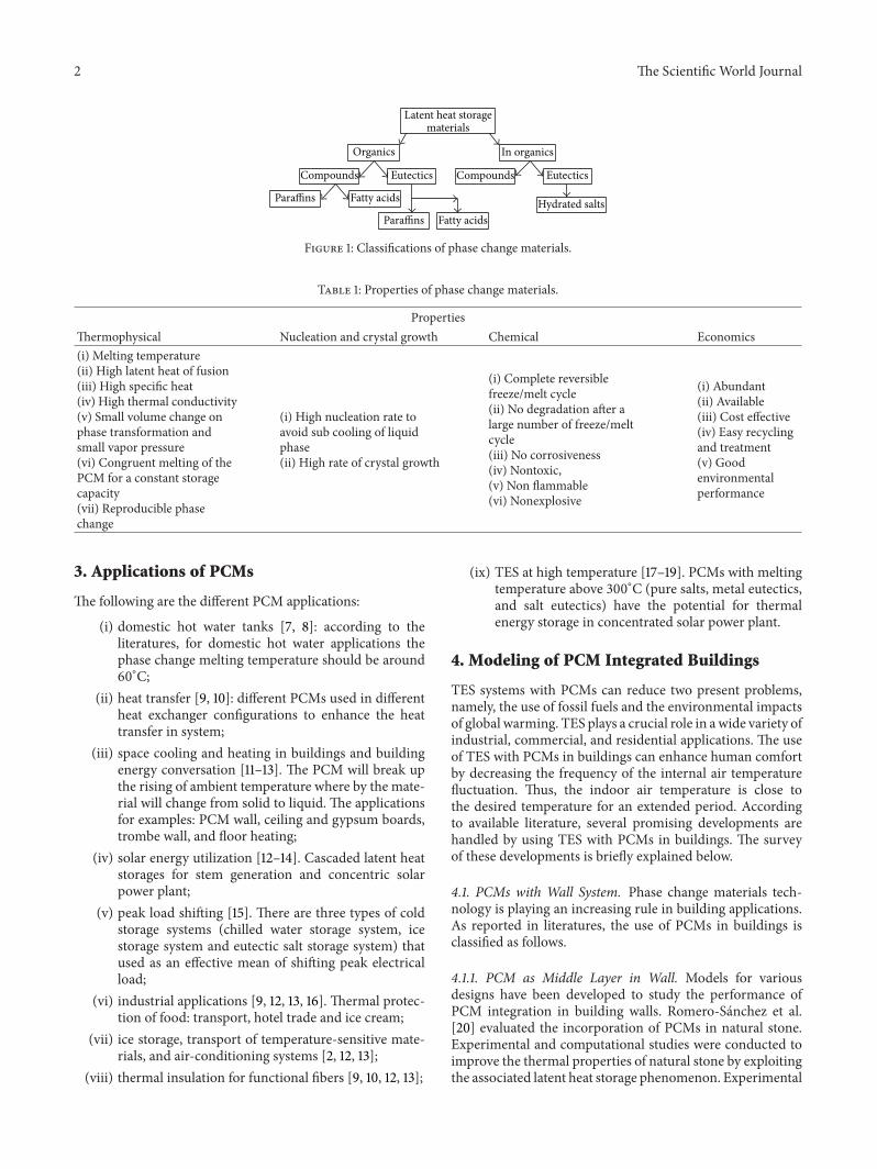
Latent heat storage materials are considered PCMs.Numerous researchers have presented the classificationsof PCMs (Figure 1) [5]. The PCMs used in the design ofa thermal storage system should have desirable chemical,kinetic, and thermophysical properties [6]. The maincharacteristics required for good PCMs are presented inTable 1.
Hindawi Publishing Corporatione Scientific World JournalVolume 2014, Article ID 391690, 11 pageshttp://dx.doi.org/10.1155/2014/391690
2 The Scientific World Journal
Latent heat storagematerials
Organics In organics
Compounds CompoundsEutectics Eutectics
Paraffins
Paraffins
Fatty acids
Fatty acidsHydrated salts
Figure 1: Classifications of phase change materials.
Table 1: Properties of phase change materials.
PropertiesThermophysical Nucleation and crystal growth Chemical Economics(i) Melting temperature(ii) High latent heat of fusion(iii) High specific heat(iv) High thermal conductivity(v) Small volume change onphase transformation andsmall vapor pressure(vi) Congruent melting of thePCM for a constant storagecapacity(vii) Reproducible phasechange
(i) High nucleation rate toavoid sub cooling of liquidphase(ii) High rate of crystal growth
(i) Complete reversiblefreeze/melt cycle(ii) No degradation after alarge number of freeze/meltcycle(iii) No corrosiveness(iv) Nontoxic,(v) Non flammable(vi) Nonexplosive
(i) Abundant(ii) Available(iii) Cost effective(iv) Easy recyclingand treatment(v) Goodenvironmentalperformance
3. Applications of PCMs
The following are the different PCM applications:
(i) domestic hot water tanks [7, 8]: according to theliteratures, for domestic hot water applications thephase change melting temperature should be around60∘C;
(ii) heat transfer [9, 10]: different PCMs used in differentheat exchanger configurations to enhance the heattransfer in system;
(iii) space cooling and heating in buildings and buildingenergy conversation [11–13]. The PCM will break upthe rising of ambient temperature where by the mate-rial will change from solid to liquid. The applicationsfor examples: PCM wall, ceiling and gypsum boards,trombe wall, and floor heating;
(iv) solar energy utilization [12–14]. Cascaded latent heatstorages for stem generation and concentric solarpower plant;
(v) peak load shifting [15]. There are three types of coldstorage systems (chilled water storage system, icestorage system and eutectic salt storage system) thatused as an effective mean of shifting peak electricalload;
(vi) industrial applications [9, 12, 13, 16]. Thermal protec-tion of food: transport, hotel trade and ice cream;
(vii) ice storage, transport of temperature-sensitive mate-rials, and air-conditioning systems [2, 12, 13];
(viii) thermal insulation for functional fibers [9, 10, 12, 13];
(ix) TES at high temperature [17–19]. PCMs with meltingtemperature above 300∘C (pure salts, metal eutectics,and salt eutectics) have the potential for thermalenergy storage in concentrated solar power plant.
4. Modeling of PCM Integrated Buildings
TES systems with PCMs can reduce two present problems,namely, the use of fossil fuels and the environmental impactsof global warming. TES plays a crucial role in awide variety ofindustrial, commercial, and residential applications. The useof TES with PCMs in buildings can enhance human comfortby decreasing the frequency of the internal air temperaturefluctuation. Thus, the indoor air temperature is close tothe desired temperature for an extended period. Accordingto available literature, several promising developments arehandled by using TES with PCMs in buildings. The surveyof these developments is briefly explained below.
4.1. PCMs with Wall System. Phase change materials tech-nology is playing an increasing rule in building applications.As reported in literatures, the use of PCMs in buildings isclassified as follows.
4.1.1. PCM as Middle Layer in Wall. Models for variousdesigns have been developed to study the performance ofPCM integration in building walls. Romero-Sanchez et al.[20] evaluated the incorporation of PCMs in natural stone.Experimental and computational studies were conducted toimprove the thermal properties of natural stone by exploitingthe associated latent heat storage phenomenon. Experimental
The Scientific World Journal 3
Exterior Interior
Cement Perforatedbrick wall Insulation Brick wall II Plaster
15 15115 40 40
IT Convectionhe
Convectionhi
T∙extamb T∙
amb int
Figure 2: A schematic diagram showing the wall layers of the typical external wall (base composite wall) used in the simulations.
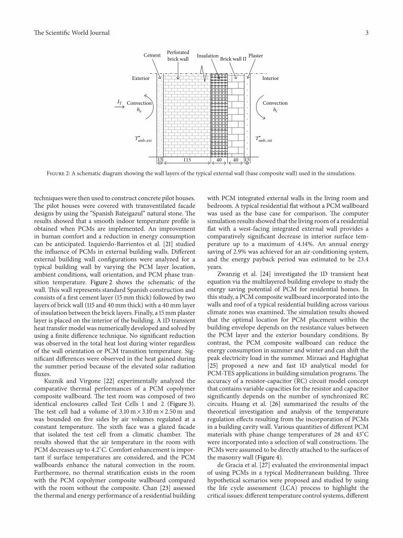
techniques were then used to construct concrete pilot houses.The pilot houses were covered with transventilated facadedesigns by using the “Spanish Bateigazul” natural stone. Theresults showed that a smooth indoor temperature profile isobtained when PCMs are implemented. An improvementin human comfort and a reduction in energy consumptioncan be anticipated. Izquierdo-Barrientos et al. [21] studiedthe influence of PCMs in external building walls. Differentexternal building wall configurations were analyzed for atypical building wall by varying the PCM layer location,ambient conditions, wall orientation, and PCM phase tran-sition temperature. Figure 2 shows the schematic of thewall. This wall represents standard Spanish construction andconsists of a first cement layer (15mm thick) followed by twolayers of brick wall (115 and 40mm thick) with a 40mm layerof insulation between the brick layers. Finally, a 15mmplasterlayer is placed on the interior of the building. A 1D transientheat transfer model was numerically developed and solved byusing a finite difference technique. No significant reductionwas observed in the total heat lost during winter regardlessof the wall orientation or PCM transition temperature. Sig-nificant differences were observed in the heat gained duringthe summer period because of the elevated solar radiationfluxes.
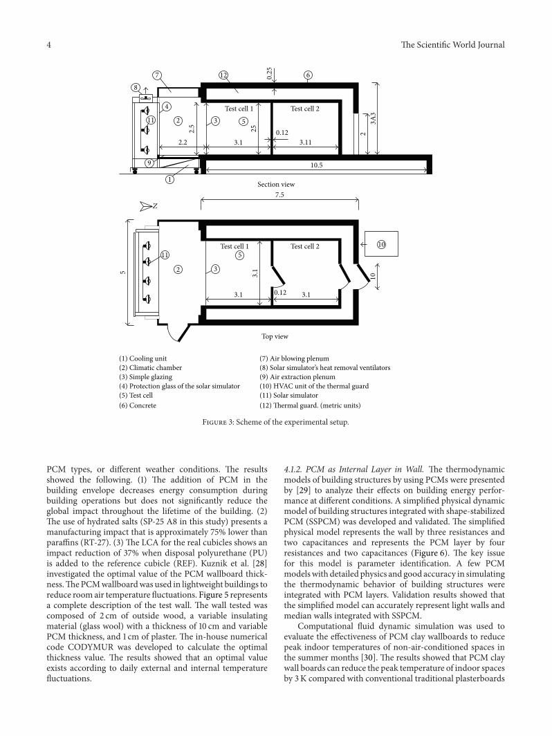
Kuznik and Virgone [22] experimentally analyzed thecomparative thermal performances of a PCM copolymercomposite wallboard. The test room was composed of twoidentical enclosures called Test Cells 1 and 2 (Figure 3).The test cell had a volume of 3.10m× 3.10m× 2.50m andwas bounded on five sides by air volumes regulated at aconstant temperature. The sixth face was a glazed facadethat isolated the test cell from a climatic chamber. Theresults showed that the air temperature in the room withPCM decreases up to 4.2∘C. Comfort enhancement is impor-tant if surface temperatures are considered, and the PCMwallboards enhance the natural convection in the room.Furthermore, no thermal stratification exists in the roomwith the PCM copolymer composite wallboard comparedwith the room without the composite. Chan [23] assessedthe thermal and energy performance of a residential building
with PCM integrated external walls in the living room andbedroom. A typical residential flat without a PCM wallboardwas used as the base case for comparison. The computersimulation results showed that the living roomof a residentialflat with a west-facing integrated external wall provides acomparatively significant decrease in interior surface tem-perature up to a maximum of 4.14%. An annual energysaving of 2.9% was achieved for an air-conditioning system,and the energy payback period was estimated to be 23.4years.
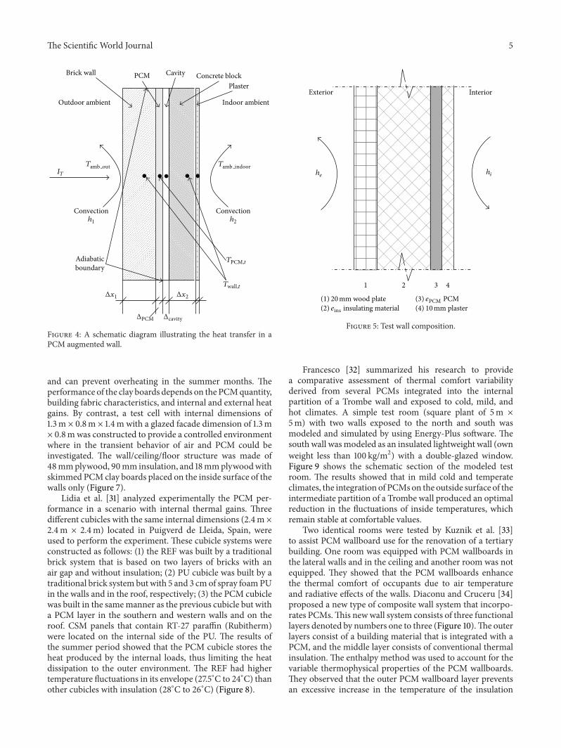
Zwanzig et al. [24] investigated the 1D transient heatequation via the multilayered building envelope to study theenergy saving potential of PCM for residential homes. Inthis study, a PCM composite wallboard incorporated into thewalls and roof of a typical residential building across variousclimate zones was examined. The simulation results showedthat the optimal location for PCM placement within thebuilding envelope depends on the resistance values betweenthe PCM layer and the exterior boundary conditions. Bycontrast, the PCM composite wallboard can reduce theenergy consumption in summer and winter and can shift thepeak electricity load in the summer. Mirzaei and Haghighat[25] proposed a new and fast 1D analytical model forPCM-TES applications in building simulation programs.Theaccuracy of a resistor-capacitor (RC) circuit model conceptthat contains variable capacities for the resistor and capacitorsignificantly depends on the number of synchronized RCcircuits. Huang et al. [26] summarized the results of thetheoretical investigation and analysis of the temperatureregulation effects resulting from the incorporation of PCMsin a building cavity wall. Various quantities of different PCMmaterials with phase change temperatures of 28 and 43∘Cwere incorporated into a selection of wall constructions. ThePCMs were assumed to be directly attached to the surfaces ofthe masonry wall (Figure 4).
de Gracia et al. [27] evaluated the environmental impactof using PCMs in a typical Mediterranean building. Threehypothetical scenarios were proposed and studied by usingthe life cycle assessment (LCA) process to highlight thecritical issues: different temperature control systems, different
4 The Scientific World Journal
1
2
2
3
3
4
5
5
67
8
9
10
11
11
12
Test cell 1 Test cell 2
Test cell 1 Test cell 2
Section view
Top view
2.5
2.2 3.1
0.12
0.12
3.11
2
10.5
3A3
0.25
7.5
3.1 3.1
3.15
25
10
Z
(1) Cooling unit(2) Climatic chamber(3) Simple glazing(4) Protection glass of the solar simulator(5) Test cell(6) Concrete
(7) Air blowing plenum(8) Solar simulator’s heat removal ventilators(9) Air extraction plenum(10) HVAC unit of the thermal guard(11) Solar simulator(12) Thermal guard. (metric units)
Figure 3: Scheme of the experimental setup.
PCM types, or different weather conditions. The resultsshowed the following. (1) The addition of PCM in thebuilding envelope decreases energy consumption duringbuilding operations but does not significantly reduce theglobal impact throughout the lifetime of the building. (2)The use of hydrated salts (SP-25 A8 in this study) presents amanufacturing impact that is approximately 75% lower thanparaffins (RT-27). (3) The LCA for the real cubicles shows animpact reduction of 37% when disposal polyurethane (PU)is added to the reference cubicle (REF). Kuznik et al. [28]investigated the optimal value of the PCM wallboard thick-ness.ThePCMwallboardwas used in lightweight buildings toreduce room air temperature fluctuations. Figure 5 representsa complete description of the test wall. The wall tested wascomposed of 2 cm of outside wood, a variable insulatingmaterial (glass wool) with a thickness of 10 cm and variablePCM thickness, and 1 cm of plaster. The in-house numericalcode CODYMUR was developed to calculate the optimalthickness value. The results showed that an optimal valueexists according to daily external and internal temperaturefluctuations.
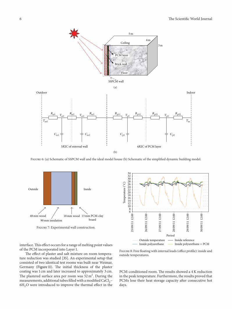
4.1.2. PCM as Internal Layer in Wall. The thermodynamicmodels of building structures by using PCMs were presentedby [29] to analyze their effects on building energy perfor-mance at different conditions. A simplified physical dynamicmodel of building structures integrated with shape-stabilizedPCM (SSPCM) was developed and validated. The simplifiedphysical model represents the wall by three resistances andtwo capacitances and represents the PCM layer by fourresistances and two capacitances (Figure 6). The key issuefor this model is parameter identification. A few PCMmodelswith detailed physics and good accuracy in simulatingthe thermodynamic behavior of building structures wereintegrated with PCM layers. Validation results showed thatthe simplified model can accurately represent light walls andmedian walls integrated with SSPCM.
Computational fluid dynamic simulation was used toevaluate the effectiveness of PCM clay wallboards to reducepeak indoor temperatures of non-air-conditioned spaces inthe summer months [30]. The results showed that PCM claywall boards can reduce the peak temperature of indoor spacesby 3K compared with conventional traditional plasterboards
The Scientific World Journal 5
Tamb out Tamb indoorIT
TPCM,t
Twall,tΔx1 Δx2
ΔPCM Δcavity
Brick wall PCM Cavity Concrete blockPlaster
Outdoor ambient Indoor ambient
h1
Convectionh2
Convection
Adiabaticboundary
Figure 4: A schematic diagram illustrating the heat transfer in aPCM augmented wall.
and can prevent overheating in the summer months. Theperformance of the clay boards depends on the PCMquantity,building fabric characteristics, and internal and external heatgains. By contrast, a test cell with internal dimensions of1.3m × 0.8m × 1.4m with a glazed facade dimension of 1.3m× 0.8mwas constructed to provide a controlled environmentwhere in the transient behavior of air and PCM could beinvestigated. The wall/ceiling/floor structure was made of48mmplywood, 90mm insulation, and 18mmplywoodwithskimmed PCM clay boards placed on the inside surface of thewalls only (Figure 7).
Lidia et al. [31] analyzed experimentally the PCM per-formance in a scenario with internal thermal gains. Threedifferent cubicles with the same internal dimensions (2.4m ×2.4m × 2.4m) located in Puigverd de Lleida, Spain, wereused to perform the experiment. These cubicle systems wereconstructed as follows: (1) the REF was built by a traditionalbrick system that is based on two layers of bricks with anair gap and without insulation; (2) PU cubicle was built by atraditional brick system but with 5 and 3 cm of spray foamPUin the walls and in the roof, respectively; (3) the PCM cubiclewas built in the samemanner as the previous cubicle but witha PCM layer in the southern and western walls and on theroof. CSM panels that contain RT-27 paraffin (Rubitherm)were located on the internal side of the PU. The results ofthe summer period showed that the PCM cubicle stores theheat produced by the internal loads, thus limiting the heatdissipation to the outer environment. The REF had highertemperature fluctuations in its envelope (27.5∘C to 24∘C) thanother cubicles with insulation (28∘C to 26∘C) (Figure 8).
Exterior Interior
1 2 3 4
he hi
20mm wood plate(1)eins insulating material(2)
ePCM PCM(3)10mm plaster(4)
Figure 5: Test wall composition.
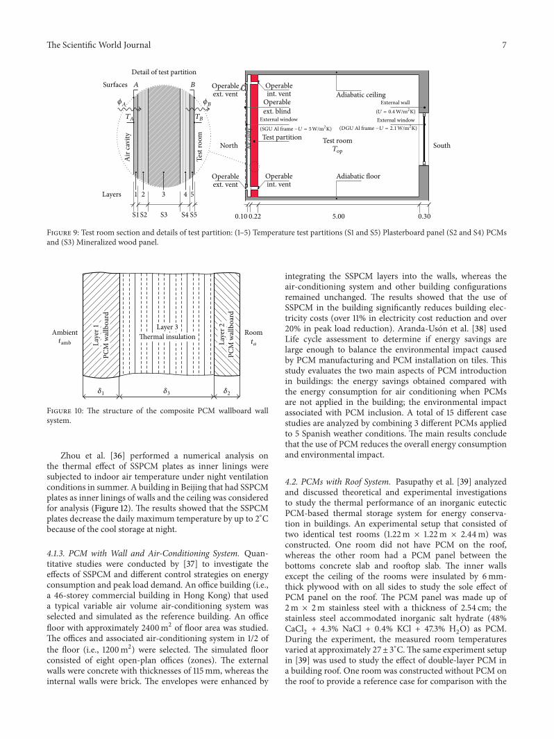
Francesco [32] summarized his research to providea comparative assessment of thermal comfort variabilityderived from several PCMs integrated into the internalpartition of a Trombe wall and exposed to cold, mild, andhot climates. A simple test room (square plant of 5m ×5m) with two walls exposed to the north and south wasmodeled and simulated by using Energy-Plus software. Thesouth wall wasmodeled as an insulated lightweight wall (ownweight less than 100 kg/m2) with a double-glazed window.Figure 9 shows the schematic section of the modeled testroom. The results showed that in mild cold and temperateclimates, the integration of PCMson the outside surface of theintermediate partition of a Trombe wall produced an optimalreduction in the fluctuations of inside temperatures, whichremain stable at comfortable values.
Two identical rooms were tested by Kuznik et al. [33]to assist PCM wallboard use for the renovation of a tertiarybuilding. One room was equipped with PCM wallboards inthe lateral walls and in the ceiling and another room was notequipped. They showed that the PCM wallboards enhancethe thermal comfort of occupants due to air temperatureand radiative effects of the walls. Diaconu and Cruceru [34]proposed a new type of composite wall system that incorpo-rates PCMs.This newwall system consists of three functionallayers denoted by numbers one to three (Figure 10).The outerlayers consist of a building material that is integrated with aPCM, and the middle layer consists of conventional thermalinsulation. The enthalpy method was used to account for thevariable thermophysical properties of the PCM wallboards.They observed that the outer PCM wallboard layer preventsan excessive increase in the temperature of the insulation
6 The Scientific World Journal
5m
4m
3mCeiling
PCM layer
Brick wall
Floor
SSPCM wall
(a)
(b)
Figure 6: (a) Schematic of SSPCM wall and the ideal model house (b) Schematic of the simplified dynamic building model.
Outside Inside
48mm wood 18mm wood90mm insulation
13mm PCM-clayboard
Figure 7: Experimental wall construction.
interface.This effect occurs for a range ofmelting point valuesof the PCM incorporated into Layer 1.
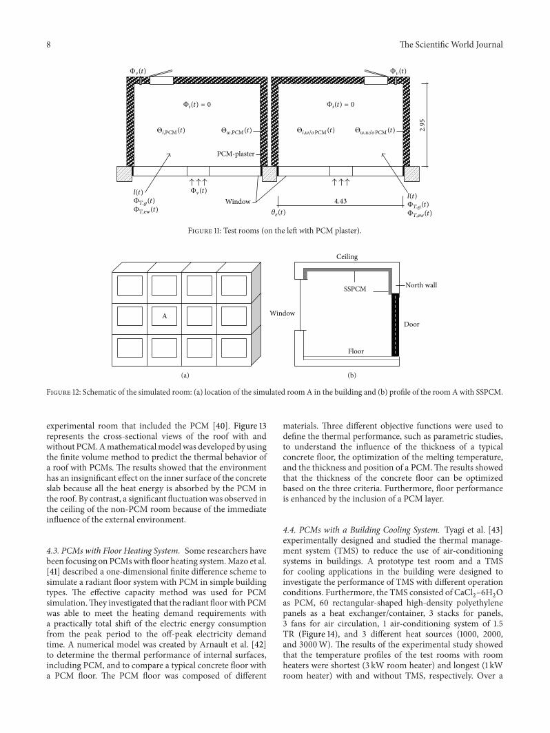
The effect of plaster and salt mixture on room tempera-ture reduction was studied [35]. An experimental setup thatconsisted of two identical test rooms was built near Weimar,Germany (Figure 11). The initial thickness of the plastercoating was 1 cm and later increased to approximately 3 cm.The plastered surface area per room was 52m2. During themeasurements, additional tubes filledwith amodifiedCaCl
2–
6H2O were introduced to improve the thermal effect in the
3432302826242220181614121086
Tem
pera
ture
(∘ C)
25/0
9/1
112
:00
26/0
9/1
112
:00
27/0
9/1
112
:00
28/0
9/1
112
:00
29/0
9/1
112
:00
30
/09
/1112
:00
PeriodOutside temperatureInside polyurethane
Inside referenceInside polyurethane + PCM
Figure 8: Free floating with internal loads (office profile): inside andoutside temperatures.
PCM-conditioned room. The results showed a 4K reductionin the peak temperature. Furthermore, the results proved thatPCMs lose their heat storage capacity after consecutive hotdays.
The Scientific World Journal 7
Detail of test partition
A BSurfaces Operableext. vent
Operableext. vent
North South
Layers 1 2 3 4 5
S1S2 S3 S4 S5
Air
cavi
ty
Test
room
𝜙A 𝜙B
TA TB
Operableint. vent
Operableint. vent
Operableext. blind
Test partition
External window
Test room
Adiabatic ceiling
Adiabatic floor
0.10 0.22 5.00 0.30
(SGU Al frame −U = 5W/m2K)
External wall(U = 0.4 W/m2K)External window
(DGU Al frame −U = 2.1 W/m2K)
Air
cavi
ty
Top
Figure 9: Test room section and details of test partition: (1–5) Temperature test partitions (S1 and S5) Plasterboard panel (S2 and S4) PCMsand (S3) Mineralized wood panel.
Ambienttamb
Roomta
𝛿1 𝛿2𝛿3
Laye
r1PC
M w
allb
oard
Laye
r2PC
M w
allb
oard
Layer 3
Thermal insulation
Figure 10: The structure of the composite PCM wallboard wallsystem.
Zhou et al. [36] performed a numerical analysis onthe thermal effect of SSPCM plates as inner linings weresubjected to indoor air temperature under night ventilationconditions in summer. A building in Beijing that had SSPCMplates as inner linings of walls and the ceiling was consideredfor analysis (Figure 12). The results showed that the SSPCMplates decrease the daily maximum temperature by up to 2∘Cbecause of the cool storage at night.
4.1.3. PCM with Wall and Air-Conditioning System. Quan-titative studies were conducted by [37] to investigate theeffects of SSPCM and different control strategies on energyconsumption and peak load demand. An office building (i.e.,a 46-storey commercial building in Hong Kong) that useda typical variable air volume air-conditioning system wasselected and simulated as the reference building. An officefloor with approximately 2400m2 of floor area was studied.The offices and associated air-conditioning system in 1/2 ofthe floor (i.e., 1200m2) were selected. The simulated floorconsisted of eight open-plan offices (zones). The externalwalls were concrete with thicknesses of 115mm, whereas theinternal walls were brick. The envelopes were enhanced by
integrating the SSPCM layers into the walls, whereas theair-conditioning system and other building configurationsremained unchanged. The results showed that the use ofSSPCM in the building significantly reduces building elec-tricity costs (over 11% in electricity cost reduction and over20% in peak load reduction). Aranda-Uson et al. [38] usedLife cycle assessment to determine if energy savings arelarge enough to balance the environmental impact causedby PCM manufacturing and PCM installation on tiles. Thisstudy evaluates the two main aspects of PCM introductionin buildings: the energy savings obtained compared withthe energy consumption for air conditioning when PCMsare not applied in the building; the environmental impactassociated with PCM inclusion. A total of 15 different casestudies are analyzed by combining 3 different PCMs appliedto 5 Spanish weather conditions. The main results concludethat the use of PCM reduces the overall energy consumptionand environmental impact.
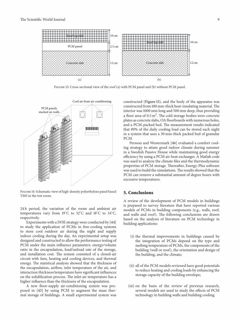
4.2. PCMs with Roof System. Pasupathy et al. [39] analyzedand discussed theoretical and experimental investigationsto study the thermal performance of an inorganic eutecticPCM-based thermal storage system for energy conserva-tion in buildings. An experimental setup that consisted oftwo identical test rooms (1.22m × 1.22m × 2.44m) wasconstructed. One room did not have PCM on the roof,whereas the other room had a PCM panel between thebottoms concrete slab and rooftop slab. The inner wallsexcept the ceiling of the rooms were insulated by 6mm-thick plywood with on all sides to study the sole effect ofPCM panel on the roof. The PCM panel was made up of2m × 2m stainless steel with a thickness of 2.54 cm; thestainless steel accommodated inorganic salt hydrate (48%CaCl2+ 4.3% NaCl + 0.4% KCl + 47.3% H
2O) as PCM.
During the experiment, the measured room temperaturesvaried at approximately 27±3∘C.The same experiment setupin [39] was used to study the effect of double-layer PCM ina building roof. One room was constructed without PCM onthe roof to provide a reference case for comparison with the
8 The Scientific World Journal
Φ�(t)
Φ�(t)
Φ�(t)
Φi(t) = 0 Φi(t) = 0
i,PCM (t) w,PCM (t)
PCM-plaster
Windowl(t)ΦT,g(t)ΦT,ew(t)
l(t)ΦT,g(t)ΦT,ew(t)𝜃e(t)
i,w/ (t) w,w/ 2.95
4.43
oPCM (t)oPCM ΘΘΘ Θ
Figure 11: Test rooms (on the left with PCM plaster).
A
(a)
Window
Ceiling
Floor
North wall
Door
SSPCM
(b)
Figure 12: Schematic of the simulated room: (a) location of the simulated room A in the building and (b) profile of the room A with SSPCM.
experimental room that included the PCM [40]. Figure 13represents the cross-sectional views of the roof with andwithout PCM.Amathematicalmodel was developed by usingthe finite volume method to predict the thermal behavior ofa roof with PCMs. The results showed that the environmenthas an insignificant effect on the inner surface of the concreteslab because all the heat energy is absorbed by the PCM inthe roof. By contrast, a significant fluctuationwas observed inthe ceiling of the non-PCM room because of the immediateinfluence of the external environment.
4.3. PCMs with Floor Heating System. Some researchers havebeen focusing on PCMswith floor heating system.Mazo et al.[41] described a one-dimensional finite difference scheme tosimulate a radiant floor system with PCM in simple buildingtypes. The effective capacity method was used for PCMsimulation.They investigated that the radiant floor with PCMwas able to meet the heating demand requirements witha practically total shift of the electric energy consumptionfrom the peak period to the off-peak electricity demandtime. A numerical model was created by Arnault et al. [42]to determine the thermal performance of internal surfaces,including PCM, and to compare a typical concrete floor witha PCM floor. The PCM floor was composed of different
materials. Three different objective functions were used todefine the thermal performance, such as parametric studies,to understand the influence of the thickness of a typicalconcrete floor, the optimization of the melting temperature,and the thickness and position of a PCM.The results showedthat the thickness of the concrete floor can be optimizedbased on the three criteria. Furthermore, floor performanceis enhanced by the inclusion of a PCM layer.
4.4. PCMs with a Building Cooling System. Tyagi et al. [43]experimentally designed and studied the thermal manage-ment system (TMS) to reduce the use of air-conditioningsystems in buildings. A prototype test room and a TMSfor cooling applications in the building were designed toinvestigate the performance of TMS with different operationconditions. Furthermore, the TMS consisted of CaCl
2–6H2O
as PCM, 60 rectangular-shaped high-density polyethylenepanels as a heat exchanger/container, 3 stacks for panels,3 fans for air circulation, 1 air-conditioning system of 1.5TR (Figure 14), and 3 different heat sources (1000, 2000,and 3000W). The results of the experimental study showedthat the temperature profiles of the test rooms with roomheaters were shortest (3 kW room heater) and longest (1 kWroom heater) with and without TMS, respectively. Over a
The Scientific World Journal 9
Roof top slab
PCM panel
Concrete slab
10 cm
2.5 cm
12 cm
(a)
Roof top slab
Concrete slab
10 cm
12 cm
(b)
Figure 13: Cross-sectional view of the roof (a) with PCM panel and (b) without PCM panel.
PCM panelsstacked on walls
Cool air from air conditioning
Figure 14: Schematic view of high-density polyethylene panel basedTMS in the test room.
24 h period, the variation of the room and ambient airtemperatures vary from 19∘C to 32∘C and 18∘C to 34∘C,respectively.
Experiments with aDOE strategywere conducted by [44]to study the application of PCMs in free-cooling systemsto store cool outdoor air during the night and supplyindoor cooling during the day. An experimental setup wasdesigned and constructed to allow the performance testing ofPCM under the main influence parameters: energy/volumeratio in the encapsulation, load/unload rate of the storage,and installation cost. The system consisted of a closed-aircircuit with fans, heating and cooling devices, and thermalenergy. The statistical analysis showed that the thickness ofthe encapsulation, airflow, inlet temperature of the air, andinteraction thickness/temperature have significant influenceson the solidification process. The inlet air temperature has ahigher influence than the thickness of the encapsulation.
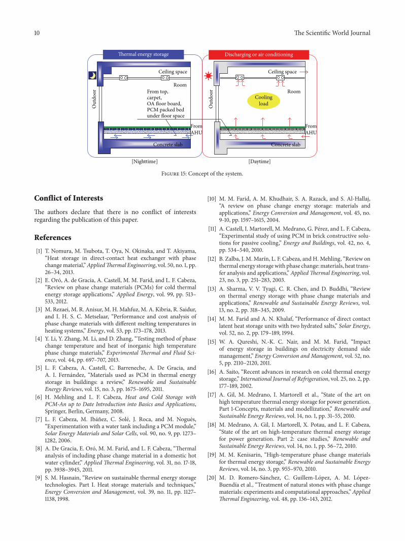
A new floor-supply air-conditioning system was pro-posed in [45] by using PCM to augment the mass ther-mal storage of buildings. A small experimental system was
constructed (Figure 15), and the body of the apparatus wasconstructed from 100mm-thick heat-insulatingmaterial.Theinterior was 1000mm long and 500mm deep, thus providinga floor area of 0.5m2. The cold storage bodies were concreteplates as concrete slabs, OAfloorboardswith numerous holes,and a PCM-packed bed. The measurement results indicatedthat 89% of the daily cooling load can be stored each nightin a system that uses a 30mm-thick packed bed of granularPCM.
Persson and Westermark [46] evaluated a comfort cool-ing strategy to attain good indoor climate during summerin a Swedish Passive House while maintaining good energyefficiency by using a PCM air-heat exchanger. A Matlab codewas used to analyze the climate files and the thermodynamicproperties of PCM storage. Thereafter, Energy-Plus softwarewas used to build the simulations.The results showed that thePCM can remove a substantial amount of degree hours withexcessive temperatures.
5. Conclusions
A review of the development of PCM models in buildingsis prepared to survey literature that have reported variousmodels of PCMs in building components (e.g., walls, roof,and walls and roof). The following conclusions are drawnbased on the analysis of literature on PCM technology inbuilding applications:
(i) the thermal improvements in buildings caused bythe integration of PCMs depend on the type andmelting temperature of PCMs, the components of thebuilding (wall or roof), the orientation and design ofthe building, and the climate;
(ii) all of the PCMmodels reviewed have good potentialsto reduce heating and cooling loads by enhancing thestorage capacity of the building envelope;
(iii) on the basis of the review of previous research,several models are used to study the effects of PCMtechnology in building walls and building cooling.
10 The Scientific World Journal
Thermal energy storage
Ceiling space Ceiling space
RoomRoom
Out
door
Out
door
FromAHU
FromAHU
[Nighttime] [Daytime]
Concrete slab Concrete slab
From top,carpet,OA floor board,PCM packed bedunder floor space
Discharging or air conditioning
Coolingload
Figure 15: Concept of the system.
Conflict of Interests
The authors declare that there is no conflict of interestsregarding the publication of this paper.
References
[1] T. Nomura, M. Tsubota, T. Oya, N. Okinaka, and T. Akiyama,“Heat storage in direct-contact heat exchanger with phasechangematerial,”AppliedThermal Engineering, vol. 50, no. 1, pp.26–34, 2013.
[2] E. Oro, A. de Gracia, A. Castell, M. M. Farid, and L. F. Cabeza,“Review on phase change materials (PCMs) for cold thermalenergy storage applications,” Applied Energy, vol. 99, pp. 513–533, 2012.
[3] M. Rezaei, M. R. Anisur, M. H.Mahfuz, M. A. Kibria, R. Saidur,and I. H. S. C. Metselaar, “Performance and cost analysis ofphase change materials with different melting temperatures inheating systems,” Energy, vol. 53, pp. 173–178, 2013.
[4] Y. Li, Y. Zhang, M. Li, and D. Zhang, “Testing method of phasechange temperature and heat of inorganic high temperaturephase change materials,” Experimental Thermal and Fluid Sci-ence, vol. 44, pp. 697–707, 2013.
[5] L. F. Cabeza, A. Castell, C. Barreneche, A. De Gracia, andA. I. Fernandez, “Materials used as PCM in thermal energystorage in buildings: a review,” Renewable and SustainableEnergy Reviews, vol. 15, no. 3, pp. 1675–1695, 2011.
[6] H. Mehling and L. F. Cabeza, Heat and Cold Storage withPCM-An up to Date Introduction into Basics and Applications,Springer, Berlin, Germany, 2008.
[7] L. F. Cabeza, M. Ibanez, C. Sole, J. Roca, and M. Nogues,“Experimentation with a water tank including a PCMmodule,”Solar Energy Materials and Solar Cells, vol. 90, no. 9, pp. 1273–1282, 2006.
[8] A. De Gracia, E. Oro, M. M. Farid, and L. F. Cabeza, “Thermalanalysis of including phase change material in a domestic hotwater cylinder,” Applied Thermal Engineering, vol. 31, no. 17-18,pp. 3938–3945, 2011.
[9] S. M. Hasnain, “Review on sustainable thermal energy storagetechnologies. Part I. Heat storage materials and techniques,”Energy Conversion and Management, vol. 39, no. 11, pp. 1127–1138, 1998.
[10] M. M. Farid, A. M. Khudhair, S. A. Razack, and S. Al-Hallaj,“A review on phase change energy storage: materials andapplications,” Energy Conversion and Management, vol. 45, no.9-10, pp. 1597–1615, 2004.
[11] A. Castell, I. Martorell, M. Medrano, G. Perez, and L. F. Cabeza,“Experimental study of using PCM in brick constructive solu-tions for passive cooling,” Energy and Buildings, vol. 42, no. 4,pp. 534–540, 2010.
[12] B. Zalba, J. M. Marın, L. F. Cabeza, and H.Mehling, “Review onthermal energy storagewith phase change:materials, heat trans-fer analysis and applications,” AppliedThermal Engineering, vol.23, no. 3, pp. 251–283, 2003.
[13] A. Sharma, V. V. Tyagi, C. R. Chen, and D. Buddhi, “Reviewon thermal energy storage with phase change materials andapplications,” Renewable and Sustainable Energy Reviews, vol.13, no. 2, pp. 318–345, 2009.
[14] M. M. Farid and A. N. Khalaf, “Performance of direct contactlatent heat storage units with two hydrated salts,” Solar Energy,vol. 52, no. 2, pp. 179–189, 1994.
[15] W. A. Qureshi, N.-K. C. Nair, and M. M. Farid, “Impactof energy storage in buildings on electricity demand sidemanagement,” Energy Conversion and Management, vol. 52, no.5, pp. 2110–2120, 2011.
[16] A. Saito, “Recent advances in research on cold thermal energystorage,” International Journal of Refrigeration, vol. 25, no. 2, pp.177–189, 2002.
[17] A. Gil, M. Medrano, I. Martorell et al., “State of the art onhigh temperature thermal energy storage for power generation.Part 1-Concepts, materials and modellization,” Renewable andSustainable Energy Reviews, vol. 14, no. 1, pp. 31–55, 2010.
[18] M. Medrano, A. Gil, I. Martorell, X. Potau, and L. F. Cabeza,“State of the art on high-temperature thermal energy storagefor power generation. Part 2: case studies,” Renewable andSustainable Energy Reviews, vol. 14, no. 1, pp. 56–72, 2010.
[19] M. M. Kenisarin, “High-temperature phase change materialsfor thermal energy storage,” Renewable and Sustainable EnergyReviews, vol. 14, no. 3, pp. 955–970, 2010.
[20] M. D. Romero-Sanchez, C. Guillem-Lopez, A. M. Lopez-Buendıa et al., “Treatment of natural stones with phase changematerials: experiments and computational approaches,”AppliedThermal Engineering, vol. 48, pp. 136–143, 2012.
The Scientific World Journal 11
[21] M. A. Izquierdo-Barrientos, J. F. Belmonte, D. Rodrıguez-Sanchez, A. E. Molina, and J. A. Almendros-Ibanez, “A numer-ical study of external building walls containing phase changematerials (PCM),” AppliedThermal Engineering, vol. 47, pp. 73–85, 2012.
[22] F. Kuznik and J. Virgone, “Experimental assessment of a phasechange material for wall building use,” Applied Energy, vol. 86,no. 10, pp. 2038–2046, 2009.
[23] A. L. S. Chan, “Energy and environmental performance ofbuilding facades integrated with phase change material insubtropical Hong Kong,” Energy and Buildings, vol. 43, no. 10,pp. 2947–2955, 2011.
[24] S. D. Zwanzig, Y. Lian, and E. G. Brehob, “Numerical simulationof phase change material composite wallboard in a multi-layered building envelope,” Energy Conversion and Manage-ment, vol. 69, pp. 27–40, 2013.
[25] P. A. Mirzaei and F. Haghighat, “Modeling of phase changematerials for applications inwhole building simulation,”Renew-able and Sustainable Energy Reviews, vol. 16, no. 7, pp. 5355–5362, 2012.
[26] M. J. Huang, P. C. Eames, and N. J. Hewitt, “The application ofa validated numerical model to predict the energy conservationpotential of using phase change materials in the fabric of abuilding,” Solar Energy Materials and Solar Cells, vol. 90, no. 13,pp. 1951–1960, 2006.
[27] A. de Gracia, L. Rincon, A. Castell et al., “Life cycle assessmentof the inclusion of phase changematerials (PCM) in experimen-tal buildings,” Energy and Buildings, vol. 42, no. 9, pp. 1517–1523,2010.
[28] F. Kuznik, J. Virgone, and J. Noel, “Optimization of a phasechange material wallboard for building use,” Applied ThermalEngineering, vol. 28, no. 11-12, pp. 1291–1298, 2008.
[29] N. Zhu, S.Wang, X. Xu, andZ.Ma, “A simplified dynamicmodelof building structures integrated with shaped-stabilized phasechangematerials,” International Journal ofThermal Sciences, vol.49, no. 9, pp. 1722–1731, 2010.
[30] B. L. Gowreesunker and S. A. Tassou, “Effectiveness of CFDsimulation for the performance prediction of phase changebuilding boards in the thermal environment control of indoorspaces,” Building and Environment, vol. 59, pp. 612–625, 2013.
[31] N. Lidia, D. G. Alvaro, S. Cristian, A. Castell, and F. C. Luisa,“Thermal loads inside buildings with phase change materials:Experimental results,” Energy Procedia, vol. 30, pp. 342–349,2012.
[32] F. Francesco, “Trombe walls for lightweight buildings in tem-perate and hot climates. Exploring the use of phase-changematerials for performances improvement,” Energy Procedia, vol.30, pp. 1110–1119, 2012.
[33] F. Kuznik, J. Virgone, and K. Johannes, “In-situ study of thermalcomfort enhancement in a renovated building equipped withphase change material wallboard,” Renewable Energy, vol. 36,no. 5, pp. 1458–1462, 2011.
[34] B. M. Diaconu and M. Cruceru, “Novel concept of compositephase change material wall system for year-round thermalenergy savings,” Energy and Buildings, vol. 42, no. 10, pp. 1759–1772, 2010.
[35] C. Voelker, O. Kornadt, and M. Ostry, “Temperature reductiondue to the application of phase change materials,” Energy andBuildings, vol. 40, no. 5, pp. 937–944, 2008.
[36] G. Zhou, Y. Yang, X. Wang, and S. Zhou, “Numerical analysisof effect of shape-stabilized phase change material plates in a
building combined with night ventilation,” Applied Energy, vol.86, no. 1, pp. 52–59, 2009.
[37] N. Zhu, S. Wang, Z. Ma, and Y. Sun, “Energy performanceand optimal control of air-conditioned buildingswith envelopesenhanced by phase change materials,” Energy Conversion andManagement, vol. 52, no. 10, pp. 3197–3205, 2011.
[38] A. Aranda-Uson, G. Ferreira, A. M. Lopez-Sabiron, M. D.Mainar-Toledo, and I. Zabalza Bribian, “Phase change materialapplications in buildings: an environmental assessment forsome Spanish climate severities,” Science of the Total Environ-ment, vol. 444, pp. 16–25, 2013.
[39] A. Pasupathy, L. Athanasius, R. Velraj, and R. V. Seeniraj,“Experimental investigation and numerical simulation analysison the thermal performance of a building roof incorporat-ing phase change material (PCM) for thermal management,”AppliedThermal Engineering, vol. 28, no. 5-6, pp. 556–565, 2008.
[40] A. Pasupathy and R. Velraj, “Effect of double layer phase changematerial in building roof for year round thermal management,”Energy and Buildings, vol. 40, no. 3, pp. 193–203, 2008.
[41] J. Mazo, M. Delgado, J. M. Marin, and B. Zalba, “Modelinga radiant floor system with Phase Change Material (PCM)integrated into a building simulation tool: analysis of a casestudy of a floor heating system coupled to a heat pump,” Energyand Buildings, vol. 47, pp. 458–466, 2012.
[42] A. Arnault, F. Mathieu-Potvin, and L. Gosselin, “Internal sur-faces including phase change materials for passive optimal shiftof solar heat gain,” International Journal ofThermal Sciences, vol.49, no. 11, pp. 2148–2156, 2010.
[43] V. V. Tyagi, D. Buddhi, R. Kothari, and S. K. Tyagi, “Phasechange material (PCM) based thermal management system forcool energy storage application in building: an experimentalstudy,” Energy and Buildings, vol. 51, pp. 248–254, 2012.
[44] B. Zalba, J. M. Marın, L. F. Cabeza, and H. Mehling, “Free-cooling of buildings with phase changematerials,” InternationalJournal of Refrigeration, vol. 27, no. 8, pp. 839–849, 2004.
[45] K. Nagano, S. Takeda, T. Mochida, K. Shimakura, and T.Nakamura, “Study of a floor supply air conditioning systemusing granular phase changematerial to augment buildingmassthermal storage—heat response in small scale experiments,”Energy and Buildings, vol. 38, no. 5, pp. 436–446, 2006.
[46] J. Persson and M. Westermark, “Phase change material coolstorage for a Swedish Passive House,” Energy and Buildings, vol.54, pp. 490–495, 2012.

TribologyAdvances in
Hindawi Publishing Corporationhttp://www.hindawi.com Volume 2014
International Journal of
AerospaceEngineeringHindawi Publishing Corporationhttp://www.hindawi.com Volume 2014
FuelsJournal of
Hindawi Publishing Corporationhttp://www.hindawi.com Volume 2014
Journal ofPetroleum Engineering
Hindawi Publishing Corporationhttp://www.hindawi.com Volume 2014
Industrial EngineeringJournal of
Hindawi Publishing Corporationhttp://www.hindawi.com Volume 2014
Power ElectronicsHindawi Publishing Corporationhttp://www.hindawi.com Volume 2014
Advances in
CombustionJournal of
Hindawi Publishing Corporationhttp://www.hindawi.com Volume 2014
Journal of
Hindawi Publishing Corporationhttp://www.hindawi.com Volume 2014
Renewable Energy
Submit your manuscripts athttp://www.hindawi.com
Hindawi Publishing Corporationhttp://www.hindawi.com Volume 2014
StructuresJournal of
International Journal of
RotatingMachinery
Hindawi Publishing Corporationhttp://www.hindawi.com Volume 2014
EnergyJournal of
Hindawi Publishing Corporationhttp://www.hindawi.com Volume 2014
Hindawi Publishing Corporation http://www.hindawi.com
Journal ofEngineeringVolume 2014
Hindawi Publishing Corporation http://www.hindawi.com Volume 2014
International Journal ofPhotoenergy
Hindawi Publishing Corporationhttp://www.hindawi.com Volume 2014
Nuclear InstallationsScience and Technology of
Hindawi Publishing Corporationhttp://www.hindawi.com Volume 2014
Solar EnergyJournal of
Hindawi Publishing Corporationhttp://www.hindawi.com Volume 2014
Wind EnergyJournal of
Hindawi Publishing Corporationhttp://www.hindawi.com Volume 2014
Nuclear EnergyInternational Journal of
Hindawi Publishing Corporationhttp://www.hindawi.com Volume 2014
High Energy PhysicsAdvances in
The Scientific World JournalHindawi Publishing Corporation http://www.hindawi.com Volume 2014