REVERSE DRAW CROSSBOW ASSEMBLY MANUAL
8
PROUDLY MADE IN THE U.S.A. FOR ALL REVERSE DRAW CROSSBOW MODELS MANUFACTURED BY TENPOINT CROSSBOW TECHNOLOGIES ® HORTON CROSSBOW INNOVATIONS ® WICKED RIDGE CROSSBOWS ® TO REDUCE YOUR RISK OF SERIOUS INJURY, YOU MUST READ, WATCH AND FOLLOW ALL WRITTEN AND VIDEO WARNINGS AND INSTRUCTIONS PROVIDED WITH THIS PRODUCT. IF YOU HAVE ANY QUESTIONS OR ARE UNSURE ABOUT ANYTHING IN THE WARNINGS AND INSTRUCTIONS, STOP AND CONTACT THE CUSTOMER SERVICE DEPARTMENT AT: 330-628-9245 OPTION 2. 1 REVERSE DRAW CROSSBOW ASSEMBLY MANUAL Reverse Draw crossbows, RDX, need minimal assembly prior to their first use. Installation of the scope and string stop block (w/foot stirrup) is required. Although we do not recommend disassembling your RDX crossbow, the disassembly and complete assembly instructions are listed below. OUT-OF-THE-BOX ASSEMBLY 1. Attach the scope and rings to the dovetail mount in the desired position (photo 1). To avoid lens damage, tighten the bottom screws on the scope rings first, leaving a slight gap between the ring sections at the top. 2. Install string stop block (w/foot stirrup), assembly bolt, and washers (photo 2). REVERSE DRAW CROSSBOW ASSEMBLY MANUAL Install scope. Install string stop block. 1 2
Transcript of REVERSE DRAW CROSSBOW ASSEMBLY MANUAL
PROUDLY MADE IN THE U.S.A.
FOR ALL REVERSE DRAW CROSSBOW MODELS MANUFACTURED BY
TENPOINT CROSSBOW TECHNOLOGIES®
HORTON CROSSBOW INNOVATIONS®
WICKED RIDGE CROSSBOWS®
TO REDUCE YOUR RISK OF SERIOUS INJURY, YOU MUST READ, WATCH AND FOLLOW ALL WRITTEN AND VIDEO WARNINGS AND INSTRUCTIONS PROVIDED WITH THIS PRODUCT. IF YOU
HAVE ANY QUESTIONS OR ARE UNSURE ABOUT ANYTHING IN THE WARNINGS AND INSTRUCTIONS, STOP AND CONTACT THE CUSTOMER SERVICE DEPARTMENT AT: 330-628-9245 OPTION 2.
1 REVERSE DRAW CROSSBOW ASSEMBLY MANUAL
Reverse Draw crossbows, RDX, need minimal assembly prior to their first use. Installation of the scope and string stop block (w/foot stirrup) is required. Although we do not recommend disassembling your RDX crossbow, the disassembly and complete assembly instructions are listed below.
OUT-OF-THE-BOX ASSEMBLY 1. Attach the scope and rings to the dovetail mount in the desired position (photo 1). To avoid lens damage, tighten the bottom screws on the scope rings first, leaving a slight gap between the ring sections at the top.
2. Install string stop block (w/foot stirrup), assembly bolt, and washers (photo 2).
REVERSE DRAW CROSSBOW ASSEMBLY MANUAL
Install scope. Install string stop block.
1 2

2 REVERSE DRAW CROSSBOW ASSEMBLY MANUAL
CARBON NITRO RDX DISASSEMBLY
1. Remove the scope. NOTE: Start by loosening the top scope screws before loosening the bottom screws (photo 3).
2. Remove the string stop block and its assembly bolt with washers (photo 4). NOTE: Do not remove the foot stirrup.
3. Using a T25 Torx bit, remove the #10 x 1" self-tapping tang screw located behind the trigger box (photo 5).
4. Remove the stock screws. Start with the stock screw closest to the butt and work your way forward to the front of the crossbow (photo 6).
5. Remove the two 1/4" -20 x 3/4" counter-sink screws from the bottom of the riser (photo 7).
6. Tilt the riser downward and slide it out of the barrel (photo 8).
CARBON NITRO RDX ASSEMBLY1. Apply a small amount of the sample lubricant to the center of each cable, then install the cable saver. NOTE: The grooved side of the cable saver sits on the cables, it does not snap on (photo 9).
2. With the barrel above the riser, slide the cable saver into the cable slot with the string sliding over the flight deck (photo 10). NOTE: Do not nick or rub the cables or string on the end of the barrel.
3. Insert and tighten the two 1/4" -20 x 3/4" counter-sink screws connecting the riser to the barrel (photo 11). Verify that both screws are tight. NOTE: The counter-sink screws should be flush with the bottom of the riser.
4. Install the stock by inserting the 1/4" – 20 x 3/4" screw in the rear stock screw hole and partially tighten (photo 12). Then, continuing forward, insert and partially tighten the two 1" screws, the 1 3/4" screw, and the second 3/4" screw. Once properly aligned, tighten all five screws completely without over-tightening.
5. Insert and tighten the #10 x 1" self-tapping tang screw (photo 13).
6. Install string stop block with stirrup, assembly bolt, and washers (photo 14).
7. Attach the scope and rings to the dovetail mount in the desired position. NOTE: For optimum eye relief, align the rear scope bell with the rear of the dovetail mount (photo 15). To avoid lens damage, tighten the bottom screws on the scope rings first, leaving a slight gap between the ring sections at the top.
Remove tang screw.
Remove screws from the bottom of the riser.
Install string stop block.
Install and partially tighten stock screws.
Remove stock screws.
Tilt riser and slide it out of the barrel.
Install cable saver.
Slide cable saver into the cable slot. Insert riser screws.
Insert tang screw.
5
7
12 13
6
8
9
10 11
14
Remove scope. Remove string stop block.
3 4
Attach scope.
15
3TENPOINTCROSSBOWS.COM
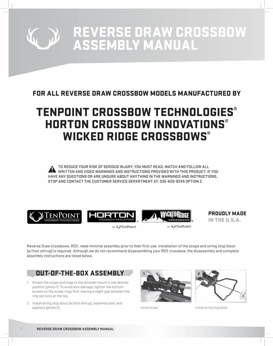
STORM RDX DISASSEMBLY1. Remove the scope. NOTE: Start by loosening the top scope screws before loosening the bottom screws (photo 16).
2. Using a T25 Torx bit, remove the #10 x 1-inch self-tapping tang screw located behind the trigger box (photo 17).
3. Remove the 1/4-20 x 1-inch and 1/4-20 x 1 3/4-inch fore-grip/ safety wing screws (photo 18).
4. Remove the 1/4-20 x 1-inch and 1/4-20 x 1 3/4-inch stock screws (photo 19).
5. Remove the string stop block and its assembly bolt with washers (photo 20).
6. Remove the two 1/4-20 x 3/4-inch counter-sink screws from the barrel channel (photo 21).
7. Tilt the riser downward and slide it out of the barrel (photo 22).
STORM RDX ASSEMBLY1. Apply a small amount of the sample lubricant to the center of each cable, then install the cable saver. NOTE: The grooved side of the cable saver sits on the cables, it does not snap on (photo 23).
2. With the barrel above the riser, slide the cable saver into the cable slot with the string sliding over the flight deck (photo 24). NOTE: Do not nick or rub the cables or string on the end of the barrel.
3. Insert & tighten the two 1/4" -20 x 3/4-inch counter-sink screws connecting the riser to the barrel (photo 25). Verify that both screws are tight. NOTE: The counter-sink screws will not be flush with, or sink into the barrel channel holes.
4. Install string stop block with stirrup, assembly bolt, and washers (photo 26).
5. Install the stock by inserting the 1/4" - 20 x 1" screw in the front stock screw hole and partially tighten, then the 1/4" - 20 x 1 3/4" screw in the rear hole and partially tighten (photo 27). Once properly aligned, tighten both screws completely without over-tightening.
6. Attach the fore-grip and safety wing by inserting the 1/4"-20 x 1" screw in the front stock screw hole and partially tighten, then the 1/4" - 20 x 1 3/4" screw in the rear hole and partially tighten (photo 28). Once properly aligned, tighten both screws completely without over-tightening.
Remove tang screw.
Remove fore-grip/safety wing screws.
Remove scope.
16 17
18
Remove barrel channel screws.
Tilt riser and slide it out of the barrel.
Remove stock screws.
Remove string stop block.
19
20 21
22
Slide cable saver into the cable slot.Install cable saver.
23 24
25
Insert barrel channel screws. Install string stop block.
Install stock and screws.
26
27
Attach fore-grip and safety wing.
28

4 REVERSE DRAW CROSSBOW ASSEMBLY MANUAL
VORTEC RDX ASSEMBLY1. Apply a small amount of the sample lubricant to the center of each cable, then install the cable saver. NOTE: The grooved side of the cable saver sits on the cables, it does not snap on (photo 36).
2. With the barrel above the riser, slide the cable saver into the cable slot with the string sliding over the flight deck (photo 37). NOTE: Do not nick or rub the cables or string on the end of the barrel.
3. Insert & tighten the two 1/4’’ - 20 x 3/4’’ counter-sink screws connecting the riser to the barrel (photo 38). Verify that both screws are tight. NOTE: The counter-sink screws should be recessed into the riser about 1/8".
4. Attach the grip plug using the 8/32" x 1/2" socket-head cap screw (photo 39).
5. Attach the fore-grip with the two #10 x 1’’ tri-lobe self-tapping screws. Use a T25 Torx bit to tighten the screws (photo 40).
6. Install string stop block with stirrup, assembly bolt, and washers (photo 41).
7. Insert and tighten the #10 x 1" self-tapping tang screw (photo 29).
8. Attach the scope and rings to the dovetail mount in the desired position. NOTE: For optimum eye relief, align the rear scope bell with the rear of the dovetail mount (photo 30). To avoid lens damage, tighten the bottom screws on the scope rings first, leaving a slight gap between the ring sections at the top.
VORTEC RDX DISASSEMBLY1. Remove the string stop block and its assembly bolt with washers (photo 31). NOTE: Do not remove the foot stirrup.
2. Using a T25 Torx bit, remove the two #10 x 1’’ tri-lobe self-tapping screws located in the fore-grip (photo 32).
3. Remove the 8/32" x 1/2" socket-head cap screw from the grip plug (photo 33).
4. Remove the two 1/4" -20 x 3/4" counter-sink screws from the bottom of the riser (photo 34).
5. Tilt the riser downward and slide it out of the barrel (photo 35).
Remove fore-grip.
Remove grip plug.
Attach grip plug.
Install cable saver. Slide cable saver into the cable slot.
Insert barrel channel screws.
Tilt riser and slide it out of the barrel.
Install string stop block.Attach fore-grip.
32
33
39
36 37
38
35
4140
Remove screws from the bottom of the riser.
34
Remove string stop block.
31
Insert tang screw. Attach scope.
29 30
5TENPOINTCROSSBOWS.COM
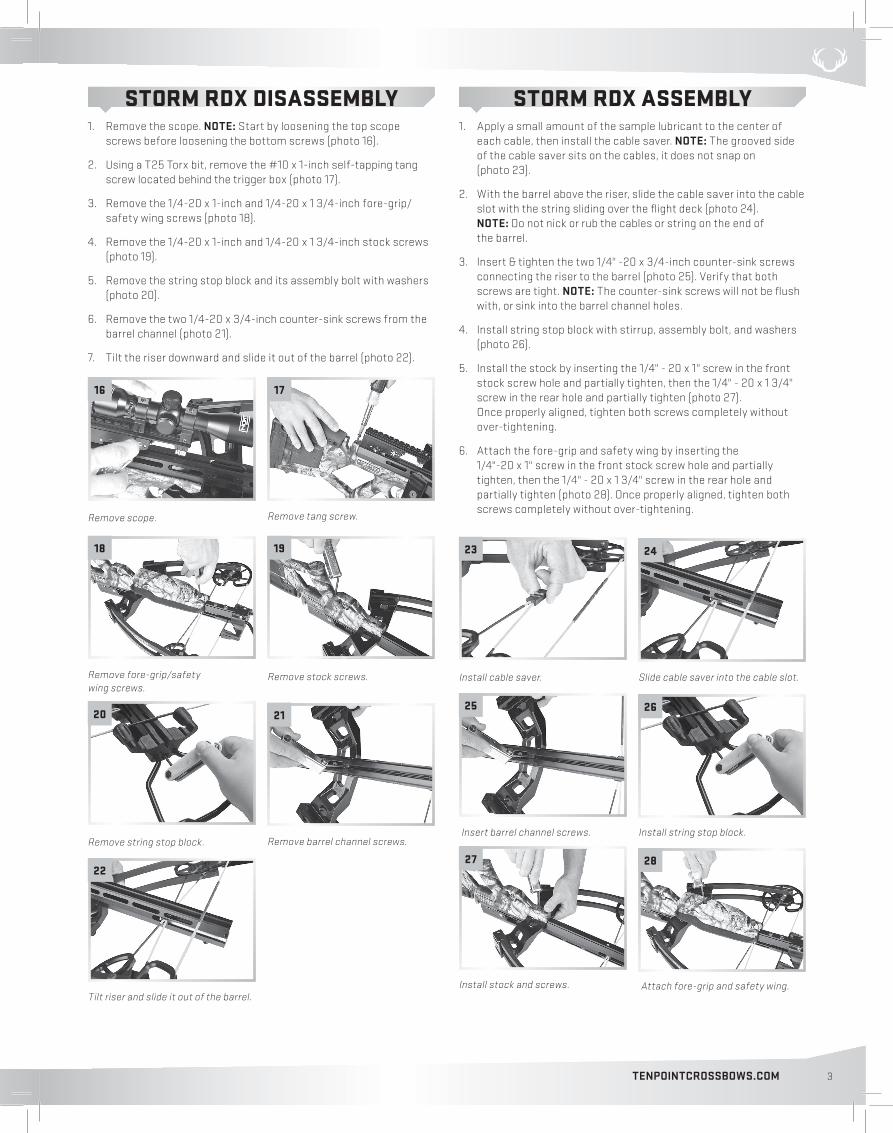
QUIVER ASSEMBLY (Follow steps 1-3 for all quiver mounting instructions)
1. The 3-arrow Instant Detach Quiver Kit contains the following parts (photo 42):
• ONE (1) Quiver• ONE (1) Quick disconnect (male) attachment• TWO (2) 3/4-inch oval counter-sink Phillips screws• ONE (1) Rubber hose (quiver hanger)• TWO (2) Hose plugs• ONE (1) Quick disconnect (female) attachment with lever• TWO (2) Phillips pan-head machine screws• ONE (1) Quiver mounting bracket with sling stud• TWO (2) 7/16-inch Nylock nuts• TWO (2) 1/4 - 20 x 3/4-inch Pan-head screws (for Carbon Nitro RDX and Storm RDX quiver mounting) • TWO (2) M5 x 20mm Tri-lobe self-tapping screws (for Vortec RDX quiver mounting)
2. Attach the rubber hose to the quiver cup. First, from the bottom of the quiver’s cup, insert both ends of the rubber hose approximately two-inches into each hole and insert a hose plug into each end. Then, pull the hose back toward the bottom of the quiver cup and seat the hose plugged ends into the counter-sunk holes (photo 43). NOTE: Once inserted, the hose plugs cannot be removed.
3. Position the quick disconnect (male) attachment to the backside of the quiver post, over the 4th and 5th holes from the quiver cup. Insert the 3/4-inch oval counter-sink Phillips screws and tighten (photo 44).
Follow steps 4-7 to mount the quiver on the Carbon Nitro RDX and Storm RDX (follow steps 4a-6a for the Vortec RDX quiver installation).
4. Remove the front sling stud and the 1/4 - 20 x 3/8-inch pan-head screw directly below it, from the bottom of the barrel (photo 45). NOTE: Use a 5/32-inch Allen wrench to remove the barrel screw.
5. Place the quiver’s mounting bracket over the two holes you just removed the sling stud and pan-head screw from. Align the mounting bracket either facing the left or right side of the crossbow, based on personal preference.
Insert and tighten the two 1/4 - 20 x 3/4-inch Pan-head screws into the same holes you removed the sling stud and barrel screw from (photo 46). Use a 5/32-inch Allen wrench to tighten.
6. Install the quick disconnect (female) attachment with lever on the quiver mounting bracket using the two Phillips pan-head machine screws and the 7/16-inch Nylock nuts. Align the open end with the lever facing the rear of the crossbow (photo 47).
7. Insert the quiver with male attachment into the quick disconnect (female) attachment with lever, and lock into place (photo 48).
Attach quick detach (male) attachment.
Remove sling stud and 3/8-inch barrel screw.
Install the quick disconnect (female) attachment.
Place the quiver bracket assembly over the two barrel holes and insert 3/4-inch screws.
Insert the 3-Arrow Instant Detach Quiver into the female bracket and lock into place with the lever.
3-Arrow Instant Detach Quiver Kit Attach rubber hose to quiver cup.
44 45
4746
48
42 43
6 REVERSE DRAW CROSSBOW ASSEMBLY MANUAL
ADJUSTING THE CHEEK PIECE & BUTT PLATE
The Horton Storm RDX is equipped with a rubber cheek piece that adjusts to any of seven fixed positions to create perfect eye-level alignment.
CHEEK PIECE ADJUSTMENT:
1. To adjust the cheek piece, remove both 3/16-inch x 1/4-inch shoulder screws using a 3/32" Allen wrench.
2. Slide the cheek piece over the desired alignment holes to create your perfect eye-level alignment (photo 52).
3. Replace the screws once you have the proper adjustment for your shooting needs. Do not over-tighten.
The TenPoint Carbon Nitro RDX and the Horton Storm RDX are equipped with an adjustable rubber butt plate to match up with a shooter’s length-of-pull.
BUTT PLATE ADJUSTMENT:
1. To adjust the rubber butt plate, remove both 3/16" x 1/4" shoulder screws using a 3/32" Allen wrench.
2. Slide the butt plate into one-of-two fixed positions (on Carbon Nitro RDX), or one-of-three fixed positions (on Storm RDX) for your perfect length-of-pull (photo 53).
3. Replace the screws once you have the proper length.
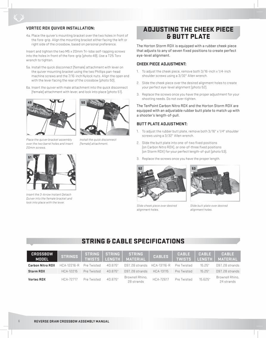
VORTEC RDX QUIVER INSTALLATION:
4a. Place the quiver’s mounting bracket over the two holes in front of the fore-grip. Align the mounting bracket either facing the left or right side of the crossbow, based on personal preference.
Insert and tighten the two M5 x 20mm Tri-lobe self-tapping screws into the holes in front of the fore-grip (photo 49). Use a T25 Torx wrench to tighten.
5a. Install the quick disconnect (female) attachment with lever on the quiver mounting bracket using the two Phillips pan-head machine screws and the 7/16-inch Nylock nuts. Align the open end with the lever facing the rear of the crossbow (photo 50).
6a. Insert the quiver with male attachment into the quick disconnect (female) attachment with lever, and lock into place (photo 51).
STRING & CABLE SPECIFICATIONS
Place the quiver bracket assembly over the two barrel holes and insert 20mm screws.
Install the quick disconnect (female) attachment.
Insert the 3-Arrow Instant Detach Quiver into the female bracket and lock into place with the lever.
Slide cheek piece over desired alignment holes.
Slide butt plate over desired alignment holes.
49 50
51
52 53
CROSSBOW MODEL STRINGS STRING
TWISTSSTRING LENGTH
STRING MATERIAL CABLES CABLE
TWISTSCABLE
LENGTH CABLE
MATERIALCarbon Nitro RDX HCA-12216-R Pre Twisted 40.875" D97, 28 strands HCA-13116-R Pre Twisted 15.25" D97, 28 strands
Storm RDX HCA-12215 Pre Twisted 40.875" D97, 28 strands HCA-13115 Pre Twisted 15.25" D97, 28 strands
Vortec RDX HCA-72717 Pre Twisted 40.875"Brownell Rhino,
28 strandsHCA-72617 Pre Twisted 15.625"
Brownell Rhino, 24 strands

7TENPOINTCROSSBOWS.COM
NOTES:

8 REVERSE DRAW CROSSBOW ASSEMBLY MANUAL
TENPOINT CROSSBOW TECHNOLOGIES®
HORTON CROSSBOW INNOVATIONS®
WICKED RIDGE CROSSBOWS®
1325 WATERLOO ROADMOGADORE, OH 44260-9608
330-628-9245
www.tenpointcrossbows.com www.hortoncrossbows.com
www.wickedridgecrossbows.com
PERFECTION LIVES HERE.PROUDLY MADE IN THE U.S.A.