Rev4.Iss1 C-12 CRUSHER - · PDF fileRev4.Iss1 C-12 CRUSHER OPERATORS MANUAL (Machine with...
43
Rev4.Iss1 C-12 CRUSHER OPERATORS MANUAL (Machine with Transport Bogie & Folding Hopper) EXTEC SCREENS & CRUSHERS LTD HEARTHCOTE ROAD, SWADLINCOTE, DERBYSHIRE. DE11 9DU. ENGLAND. Tel:- +44 (0) 1283 212121 Fax:- +44 (0) 1283 217342 0
-
Upload
nguyenkhanh -
Category
Documents
-
view
272 -
download
10
Transcript of Rev4.Iss1 C-12 CRUSHER - · PDF fileRev4.Iss1 C-12 CRUSHER OPERATORS MANUAL (Machine with...

Rev4.Iss1 C-12 CRUSHER
OPERATORS MANUAL(Machine with Transport Bogie & Folding Hopper)
EXTEC SCREENS & CRUSHERS LTDHEARTHCOTE ROAD,
SWADLINCOTE, DERBYSHIRE.DE11 9DU. ENGLAND.
Tel:- +44 (0) 1283 212121Fax:- +44 (0) 1283 217342
0

C-12 CRUSHER
This is to certify that the machine indicated below conforms to all as parts to:Nous certfions que la machine definie ci-dessous est conforme dans sa totalite:Hiermit wird erklärt, daß untengenannte Maschine in allen Einzelheiten übereinstimmt:Si dichiara che la macchina sottoindicata e conforme in tutte le sue parti:Este documento certifica que la máquina indicada más abajo se ajusta a
The directives issued by the council of European Communities. The machine conforms with all essential health and safety requirements. As laid out in the supply of machinery (safety) Regulations 1992, also the provision and the use of work equipment 1992.All guarding on machine is in accordance with BS7300 1990.- Aux Directives du Conseil des Communatee Europeennes:- Nach den Richlinien des Europäischen Gemeinschaftsrates:- Alle Direttive de Consigliodelle Comunita Europee:- Las directivas emitidas por el Consejo de Comunidades Europeas:
89/392. CEE (91/368/CEE-93/44/CEE-93/68/CEE)89/622. CEE (98/37/EC.CEE) (92/58/EEC)E.M.C. 89/336/EEC(91/263/EEC 92/31/EEC.)-European harmonised standards- Aux Normes Europeennes Harmonisees- Und den in Einklang stehenden Europäischen Normen- Alle Norme europee armonizzate- Estándares armonizados europeos
EN 292-2EN 474-1 (EN 474-5)
Manufacturer EXTEC SCREENS & CRUSHERS TYPE C-12 CRUSHERConstructeur Hearthcote Road, Swadlincote ModeleHersteller Derbyshire, England ModellCostruttore DE11 9DU TipoFabricante Tipo
Serial No:- __________Numero de chassisFahrzeug-Ident-NrMatricolaNúmero de serie
Category MOBILE CRUSHING PLANT ENGINE DEUTZCategorie MoteurErzeugnis MotoCategoria MotoreCategoría Motor
PRODUCTION MANAGER: ____________________DATE: ___________________
DECLARATION OF CONFORMITYDECLARATION DE CONFORMITEÜBEREINSTIMMUNGSERKLÄRUNGDICHIARAZIONE DI CONFORMITADECLARACIÓN DE CONFORMIDAD
1

C-12 CRUSHER
INTRODUCTION
Congratulations on the purchase of your Extec C-12 Crusher. This machine has been designed and constructed using first class materials and it will reach you in optimum condition.
Operation of the plant contrary to the instructions contained in this manual, or modifications to the machine without the agreement of the manufacturer, will invalidate any undertakings given by the manufacturer attaching to the machine.
The manufacturer will in no way accept any liability should the machine be misused, abused or operated outside the working parameters specified by the manufacturers.
Every effort has been taken to ensure the accuracy of this manual, nevertheless, as operating conditions vary considerably, all performance data contained herein is indicative only for plant operated in accordance with the conditions set out in this manual.
It is ESSENTIAL that the operator reads and observes the safety instructions in this manual. Failure to do so will invalidate any liability the manufacturer may have.
This manual should be kept at a specific location near the machines site of operation and be available at all times.
I acknowledge receipt of this operation/safety manual, and fully understand its content and implications.
Signed ....................
Signed ................... (Extec representative)
2

C-12 CRUSHER
OPERATORS MANUAL - CONTENTSSAFETY INSTRUCTIONS Page:- 4
TRANSPORTATION DIMENSIONS Page:- 5
NOISE EMISSIONS Page:- 6
PRESTART INSTRUCTIONS Page:- 7
STARTING THE MACHINE Page:- 8
STOPPING THE MACHINE Page:- 9
REMOVING TRACTOR UNIT & BOGIE Page- 10 - 12
TRACKING/MOVING MACHINE Page:- 13 & 14
SETTING UP MACHINE Page:- 15 - 18
ADJUSTING OUTPUT SIZE Page:- 19 - 21
OPERATING MACHINE - (CRUSHING) Page:- 22 & 23
FEEDING MATERIAL INTO MACHINE Page:- 22
ADJUSTING FEEDER SPEED Page:- 23
REVERSE JAW OPERATION Page:- 24
JAW BRAKE PRESSURE ADJUSTMENT Page:- 25
MAINTENANCE Page:- 26 - 36
MAINTENANCE - (DAILY) Page:- 26 & 27
MAINTENANCE - (WEEKLY) Page:- 28 - 34
MAINTENANCE - (EVERY 250hrs) Page:- 35
MAINTENANCE - (EVERY 1000hrs) Page:- 36
COLLAPSIBLE TOGGLE Page:- 37 & 38
TROUBLE SHOOTING GUIDE Page:- 39 - 41
3

C-12 CRUSHER
SAFETY INSTRUCTIONSFor safe operation of this machine, the following instructions MUSTbe followed at ALL times:-
i) Machine must ONLY be operated by trained personnel.ii) Different countries and states often have specific legislation relating to the operation of
different types of machinery and their effects on safety and the environment. Therefore, it is the users responsibility to find out those that apply to their particular circumstances and ensure that they are complied with.
iii) Always pay attention and concentrate on the job at hand.iv) Read and follow warnings and labels.v) Read and understand this manual and all machine aspects.vi) Familiarise yourself with the surrounding work area.vii) ONLY operate this machine if guards and safety devices are in position and operative.viii) ALL personnel in the vicinity of the machine MUST wear suitable safety equipment,
i.e Safety boots, ear protection, eye protection, protective clothing, hard hat, etc.
NEVER:-
i) Run machine without guards in place.ii) Make adjustments or clean moving parts whilst machine is running.iii) Reach into the machine to clean, lubricate or adjust without first shutting off power to engine &
removing ignition key.iv) Operate the machine while under the influence of drink or drugs. (NOTE:- medicines
prescribed by your medical advisor may make you unfit to operate machinery. Always check before attempting to operate machinery)
v) Allow grease or oil to remain on platforms or the area surrounding the machine.vi) Wear clothing or jewellery that could become entangled in the moving parts of the machine.vii) Try to clear any blockage whilst any part of the machine is running.viii) Permit any flame, cigarette, spark or other heat source near fuel tank.ix) Fill fuel tank while machine is running.x) Operate this machine on 'sloping' ground.xi) Operate machine while it is lifted off ground by jacking legs.xii) Climb onto crusher or touch any moving part when the machine is runningxiii) Attempt to lift crusher using lifting points on jawstock.
NOTE:- The above list is not exhaustive, if you are unsure whether anything is unsafe, stop the machine IMMEDIATELY and contact your supervisor.
4

C-12 CRUSHER
1396
6 [4
5'-1
01 4"]
3385 [11'-114"]
2495
[8'-2
1 4"]
4625
[15'
-21 4"
]44
75 [1
4'-8
1 4"]
MA
CH
INE
TRA
NSP
OR
TATI
ON
DIM
ENSI
ON
S
TR
AN
SPO
RT
AT
ION
W
IDT
H =
274
3 (9
')
*
*
* EN
SUR
E H
OPP
ER D
OO
RS,
INLE
T C
HU
TE
CO
VER
, EX
HA
UST
ST
AC
K &
SPR
AY
BA
R A
RE
FOLD
ED D
OW
N
FOR
TR
AN
SPO
RT
AT
ION
*
BEF
OR
E TR
ANSP
ORT
ING
THIS
MAC
HIN
ERY
ALL
MEA
SURE
MEN
TS O
F TH
E M
ACH
INE
SHO
ULD
BE
CHEC
KED
TO
EN
SURE
TH
EY A
RE
WIT
HIN
TH
E LE
GAL
TRAN
SPO
RT D
IMEN
SIO
NS.
*
*
5

C-12 CRUSHER
NOISE EMISSIONSTo comply with the supply of machine (safety) regulations 1992, amended 1994, EXTEC provides the following information.
The diagram below shows decibel readings taken by Castle GA 101/701 meter - calibrated on the 13.9.94 with all systems running, sited on factory assembly line.
As stated in the Safety Instructions section of this manual, ear protection is compulsory within 10 meters of the machine when the engine and other moving parts of the machine are in operation.
7m - 77 dB10m - 77 dB
7m - 85 dB
7m - 81 dB
7m - 77 dB10m - 77 dB7m - 81 dB
7m - 85 dB
6

C-12 CRUSHER
PRESTART INSTRUCTIONSBEFORE starting this machine it is IMPERATIVE that the instructions below are followed:-
i) Ensure that this manual is read & understood by the operator. DO NOT attempt to start the machine until you are aware of ALL aspects of its operation. Any questions should be referred to your supervisor.
ii) Remove any temporary sealing.iii) Check that the machine is in good mechanical condition and that there is no component damage or loss.
Ensure all bolts and fixings are tight and that all guards are in place with all safety devices operating correctly. NEVER start machine without guards and safety devices operating correctly.
iv) Ensure that crusher chamber, feeder and conveyor belts are free of material.v) Remove all tools and equipment from the operational area. Make sure that ALL personnel are well clear of
the machine, its drives, tracks and auxiliary equipment.vi) Ensure that the checks and prestart procedures outlined in the engine manufacturers instruction manual are
complied with.vii) Check oil levels in engine and vibrating feeder.viii) Check that all drums and rollers turn freely. This should be done by hand. (NEVER attempt to touch drums
or rollers whilst machine is running.)ix) Make sure that skirting rubbers and scrapers are in good condition and working properly.x) Refit exhaust stack in vertical position.xi) Close inlet chute top cover.xii) Raise oil cooler to working position. (If Fitted)
xi) Rotate cover into position & attach chains.
chain
clamp
xii) IF FITTED - Machine is transported with oil cooler in the down position. Release transportation bolt & rotate oil cooler into position. Remove transport bracket then
attach cover plate to deck & retain oil cooler with stay bar.
bolt
Cover
Stay B
ar
x) Machine is transported with exhaust stack in a lowered position. Release exhaust clamp & rotate stack to a vertical position. Re-tighten clamp.
xi) Machine is transported with inlet chute cover in the open position.
7

C-12 CRUSHER
STARTING SEQUENCE
COLD START:- When starting the machine in temperatures of 0°C or below, run all systems at engine speed No.1 for 15 minutes to allow hydraulic oil to reach working temperature. DO NOT feed material into machine during this time. When this is done stop all systems, turn engine speed switch to No.2 & restart all systems. DO NOT turn engine speed switch from position 1 to 2 while any systems are running. See page 22 for proper sequence to start systems running - DO NOT operate systems contrary to these instructions.
NOTE:- The machine MUST be level in both longitudinal and traverse planes and set up on firm level ground before being operated. Failure to comply with this or any other instructions in this manual may cause damage to the machine and may invalidate any warranty.
i) Set speed control to No.1 positionii) Turn key clockwise to 'on' position. All lights will flash for
several seconds. iii) Turn key to 'start' position and hold until engine starts.iv) Release key. (Key will return to 'on' position)v) Engine is now running at idling speed.
2:- Speed control
1:- OPEN ELECTRICAL CONTROL BOX1 Emergency Stop2 Ignition Key (ON/OFF)3 Warning Lights4 Engine Speed Control5 Engine R.P.M Meter6 Interlock (ON/OFF)7 Main Conveyor (ON/OFF)8 Side Conveyor (ON/OFF)9 Magnet (ON/OFF)10 Crusher (ON/OFF)11 Feeder (ON/OFF)12 Crusher Reverse (ON/OFF)13 Tracks (ON/OFF)14 Main Conveyor (UP/DOWN)
14
13
7
8
9
10
11
4
121 6
2
3 5
Ignitio
n Key
8

C-12 CRUSHER
STOPPING THE MACHINETo stop the machine, it is ESSENTIAL that the following steps be followed - in order to preventdamage to the machine:-
i) Stop feeding material into hopper.ii) Wait for all material to fully discharge from feeder, crusher chamber and conveyor belts.iii) Shut down systems in following order using "stop" buttons in electrical control box:-
a) Feederb) Crusherc) Main conveyord) Magnete) Side conveyor
iv) Wait for each system to come to a complete stop.v) Turn engine speed switch to position No.1 and allow engine to idle briefly.vi) Stop engine by turning ignition key to 'off' position
STOPPING MACHINE IN AN EMERGENCY
THE MACHINE CAN BE STOPPED IN AN EMERGENCY BY PRESSING THE EMERGENCYSTOP BUTTONS LOCATED ON THE ELECTRICAL CONTROL PANEL AND ALONG EACH SIDE OF THE MACHINE OR BY TURNING THE IGNITION KEY DIRECTLY TO 'OFF' POSITION.
ENSURE THAT ALL PERSONNEL IN THE VICINITY OF THE MACHINE ARE FULLY AWARE OFTHE LOCATIONS OF THE EMERGENCY STOPS.
1:- Emergency stop & ignition switch in control box.
2:- Emergency stop on L/H walkway ladder.
3:- Emergency stop on L/H side of crusher box.
4:- Emergency stop on R/H side walkway ladder.
5:- Emergency stop on R/H side of crusher box.
Note:-i) Emergency stop switches should only be used in an emergency as frequent use will cause damage to hydraulic components.
ii) Switches must be reset before the machine can be restarted.
9
C-12 CRUSHER
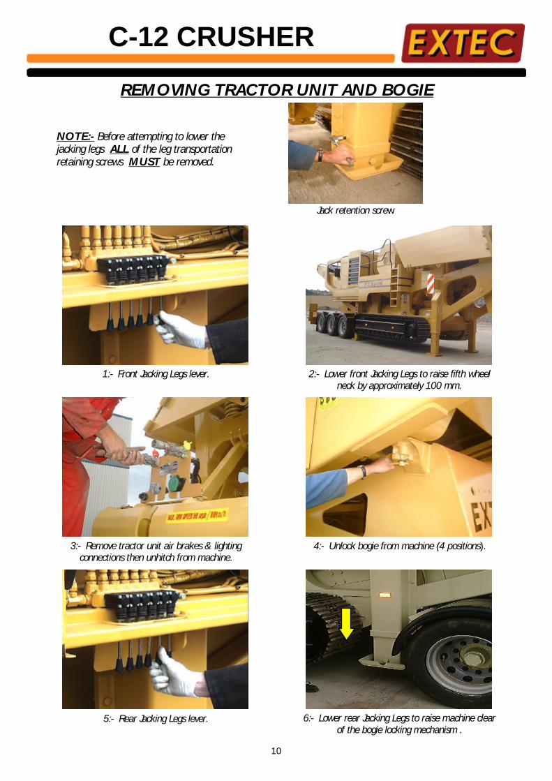
REMOVING TRACTOR UNIT AND BOGIE
3:- Remove tractor unit air brakes & lighting connections then unhitch from machine.
1:- Front Jacking Legs lever. 2:- Lower front Jacking Legs to raise fifth wheel neck by approximately 100 mm.
4:- Unlock bogie from machine (4 positions).
5:- Rear Jacking Legs lever. 6:- Lower rear Jacking Legs to raise machine clear of the bogie locking mechanism .
NOTE:- Before attempting to lower the jacking legs ALL of the leg transportation retaining screws MUST be removed.
Jack retention screw
10
C-12 CRUSHER
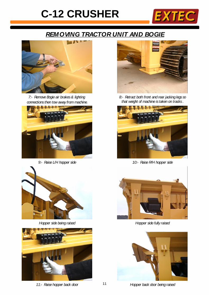
REMOVING TRACTOR UNIT AND BOGIE
7:- Remove Bogie air brakes & lighting connections then tow away from machine.
8:- Retract both front and rear jacking legs so that weight of machine is taken on tracks .
10:- Raise R/H hopper side9:- Raise L/H hopper side
Hopper back door being raised11:- Raise hopper back door
Hopper side fully raisedHopper side being raised
11
C-12 CRUSHER
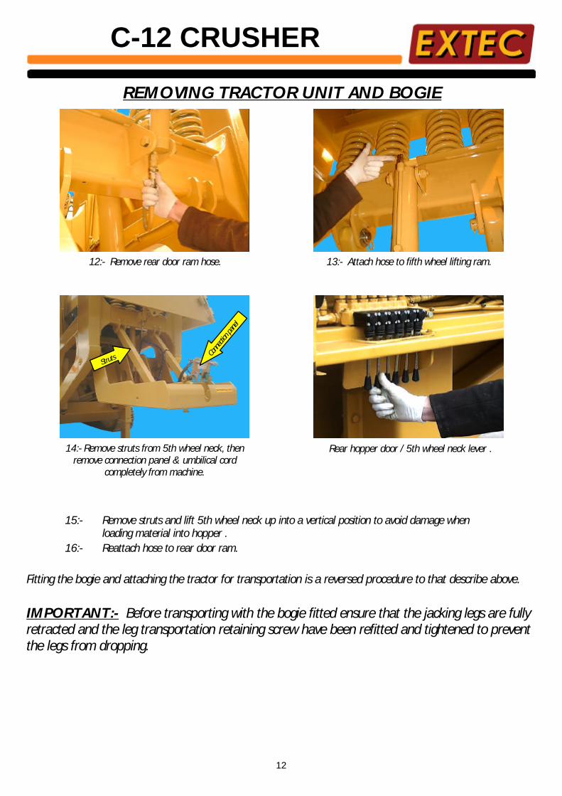
REMOVING TRACTOR UNIT AND BOGIE
12:- Remove rear door ram hose. 13:- Attach hose to fifth wheel lifting ram.
14:- Remove struts from 5th wheel neck, then remove connection panel & umbilical cord
completely from machine.
Rear hopper door / 5th wheel neck lever .
15:- Remove struts and lift 5th wheel neck up into a vertical position to avoid damage when loading material into hopper .
16:- Reattach hose to rear door ram.
Fitting the bogie and attaching the tractor for transportation is a reversed procedure to that describe above.
IMPORTANT:- Before transporting with the bogie fitted ensure that the jacking legs are fully retracted and the leg transportation retaining screw have been refitted and tightened to prevent the legs from dropping.
Struts Co
nnect
ion pa
nel
12
C-12 CRUSHER
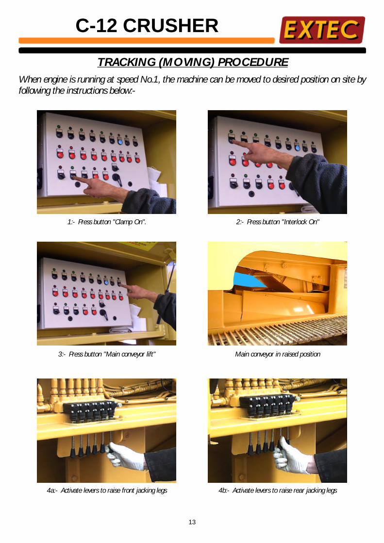
TRACKING (MOVING) PROCEDUREWhen engine is running at speed No.1, the machine can be moved to desired position on site by following the instructions below:-
Main conveyor in raised position
2:- Press button "Interlock On"
3:- Press button "Main conveyor lift"
4a:- Activate levers to raise front jacking legs 4b:- Activate levers to raise rear jacking legs
1:- Press button "Clamp On".
13

C-12 CRUSHER
5:- Press button "Tracks On"Jacking legs fully raised
After following instructions on the previous page, use either the Remote handset or Hard Wire Drive to move machine to desired position.
NOTE:- The Remote Handset will be supplied as either yellow or white (Not Both) and must be fully recharged at regular intervals. PLEASE use the correct instructions for your type of controller.
Plug in Umbilical socket for Hard wire drive.
Yellow Remote Handset.
WARNING:- Under NO circumstances try to move the machine when engine speed is set at position No.2 or when ANY personnel are standing on the machine.
For safety reasons, it is essential to check all around machine for obstacles or personnel which may be endangered by moving the machine.
When moving machine, ensure that it is only moved over firm ground suitable for carrying the weight of the machine. Prior to operating the machine, it is ESSENTIAL that both tracks are in contact with firm level ground to avoid excessive vibration or rocking of the machine. DO NOT MOVE THE MACHINE ACROSS EXCESSIVELY SLOPING GROUND.
NOTE:- i) When operating the Yellow Remote Handset, the directional arrows relate to the machines forward & reverse movement.
ii) When operating the White Remote Handset, the yellow buttons are for forward movement and the blue ones for reverse. (These correspond to direction indicator stickers on machine)
iii) When operating the Hard Wire Handset, the yellow buttons are for forward movement and the blue ones for reverse. (These correspond to direction indicator stickers on machine)
When the machine is moved to its desired operating position, prepare the crusher for operation by following the procedures laid out in the following pages.
White Remote Handset.
OR
Hard Wire Handset.
14

C-12 CRUSHER
PREPARING THE CRUSHER FOR OPERATION
Main conveyor in working position
5:- Raise R/H hopper side
2:- Press button "Interlock On"
4:- Raise L/H hopper side
3:- Press button "main conveyor lower"
1:- Press button "Clamp On"
15

C-12 CRUSHER
PREPARING THE CRUSHER FOR OPERATION Cont.
Hopper back door being raised
8:- Fit hopper cross-tie box & secure with pins & R-clip
6:- Raise hopper back door
7:- Fit locking pins to hopper sides/rear
Hopper side fully raisedHopper side being raised
16

C-12 CRUSHER
PREPARING THE CRUSHER FOR OPERATION Cont.
10:- Remove side conveyor locking pin
11:- Activate lever marked "Side Con Fold" to lower side conveyor.
Side conveyor in working position
12b:- Fix main conv. spray bar in working position.12a:- Raise main conv. spray bar to working position.
Locking Pin
9:- Fit & tighten bolts at hopper leg/chassis. (Both sides)
17

C-12 CRUSHER
PREPARING THE CRUSHER FOR OPERATION Cont.
13a:- Locate safety gate in holes in RH side walkway.
15:- Fit pins & R-clips to jack legs (8 off)
WARNING:- a) Ensure the machine is on a level surface before operating the jack leg levers.b) Lift the machine uniformly.
13b:- Push safety gate firmly down into holes.
13c:- Raise up rotating gate section. (NOTE:- while operator is using the platforms the safety gates
MUST be closed).
13d:- Rotate & lower gate into position. Repeat procedure on other side of machine.
14:- Lower jack legs by operating levers.
18

C-12 CRUSHER
SETTING MATERIAL OUTPUT SIZE:
The C-12 crusher has an adjustable discharge setting capacity. To set the size of the output material, carry out the following procedure :
WARNING:- The machine MUST be stationary and the crusher turned off whilst this procedure is carried out.
2:- Restart machine as described on page 8 and leave speed switch at position No.1.
1:- Stop the machine as described on page 9.
NOTE :- MACHINE MUST BE SHUT DOWN AND RESTARTED(SEE STEPS 1 & 2) BEFORE JAW CAN BE OPENED / CLOSED.
Ignition Key
19

C-12 CRUSHER
SETTING MATERIAL OUTPUT SIZE Cont.
3:- Press button "Jaw adjust on" 4a:- Press button "Jaw in" to close up Jaw.
4b:- Press button "Jaw out" to open up Jaw. 5:- Lock jaw when adjustment is complete.
USING REMOTE PENDENT FOR SETTING MATERIAL OUTPUT SIZE
1:- Turn to remote. 2:- Remote pendent for opening jaw
JAW CL
OSE
JAW O
PEN
STOP
20

C-12 CRUSHER
SETTING MATERIAL OUTPUT SIZE Cont.
Alignment arrow points vertically up at minimum jaw opening.
Use suitable measuring equipment - ideally callipers - tomeasure distance between opposing points on jaw plates atminimum jaw opening, known as closed size setting - (CSS).Measure jaw plates at opposing points as shown below:-
The crusher must not be operated at Closed SizeSettings (CSS) of less than 75mm (3") without priorapproval in writing from Extec
Determining when the jaw is fully closed can be done by examining the position of the alignment arrow on the jawstock shaft end plate. When the indicator arrow is pointing vertically up, the jawstock is in its fully closed position. This can be seen by looking through the slotted area on the flywheel guards. Use crusher operating buttons on engine idle speed.
Look through slotted area on guard at alignment arrow on shaft end plate.
21

C-12 CRUSHER
OPERATING THE MACHINE (CRUSHING)
Prior to loading material into machine, ensure that machine is not vibrating or rocking excessively. Stabilise with jacking legs if required, or relocate machine to more suitable ground.
2:- Start systems as per above sequence1:- Turn engine speed switch to position No.2
When the machine is set up as described in the previous pages, it is now ready to be operated. To operate machine, turn engine speed to No.2 position and then start systems in the following sequence:-
i) SIDE CONVEYORii) MAGNET DO NOT START THESE SYSTEMS IF THEYiii) MAIN CONVEYOR ARE FULL OF MATERIAL.. CLEAR ANY MATERIALiv) CRUSHER AWAY BEFORE STARTING.v) FEEDER
LOADING MATERIAL INTO MACHINE:
i) Feeder MUST be running PRIOR to feed material being placed upon it.. DO NOT start feeder if it is full of material.
ii) Material which is larger than 80% of feeder discharge chute should not be presented to the feeder. STOP MACHINE and remove any large pieces of material with the appropriate equipment. DO
NOT use excavator to force any material into feeder as any damage occurred from this action will invalidate any EXTEC warrantees.
iii) Material should be fed carefully, (not dropped onto feeder) from about 300mm above feeder. Ensure that feeder is evenly loaded over its entire length - excluding grizzly - this is to help with screening fines material and to maximise production.
iv) It is recommended that an excavator is used to load material into hopper. DO NOT OVER FILL HOPPER.
v) For maximum output and minimum wear, it is recommended that the crusher chamber is fed consistently with the supply of material being steady and constant. STOP/START OPERATION OF
THE FEEDER SHOULD BE AVOIDED.vi) Pressure Switches are fitted to the crusher box side plate and should the crusher chamber become
overfilled for "X" minutes ( "X" being adjustable to suit material ) the feeder will STOP until the material is reduced to an acceptable level. (See photographs on next page for adjusting feeder control speed & feeder cut out switch).
22

C-12 CRUSHER
OPERATING THE MACHINE (CRUSHING) Cont.
Adjusting feeder speed using Webtec control. Starting/Stopping feeder speed using remote control.
When the machine is set up as described in the previous pages, it is now ready to be used to crush desired material. DO NOT START CRUSHING UNTIL YOU HAVE READ AND UNDERSTOOD THIS MANUAL.
WEBTEC
Feeder cut out switch - off
FEEDER CUT-OUT:-
The C-12 crusher is fitted with a pressure sensing device that will cut out the operation of the feeder when the pressure in the crusher chamber exceeds specified limits. This reduces the chances of the crusher becoming choked with material, as the machine will have more time to deal with what is in the crusher chamber.
Once the pressure in the crusher chamber drops to within specified limits, the feeder will automatically restart to give an uninterrupted crushing process. This system reduces the chances of having to manually clear the crusher chamber and reduces the amount of down time.
Feeder cut out switch - on.
High Pressure.Feeder cuts out when
pressure in crusher box goes above 200 bar.
Low Pressure.Feeder starts up again automatically when
pressure drops below 120 bar.
23

C-12 CRUSHER
REVERSE JAW OPERATION
CRUSHER REVERSE OFFCRUSHER REVERSE ON
When crushing, the jaw of the machine may become jammed with material. If this happens, the direction of crushing can be reversed in order to free the material. To do this, proceed as follows:-
i) Stop the crusher ii) Close down all running systems (see page 9)iii) Switch engine to No.1 position & Restart all running systems (see page 22) except crusher
(Use Crusher Reverse on)iv) Run crusher in reverse until material has become loose.v) Close down all running systems (see page 9) (Use Crusher Reverse off)vi) Switch engine to No.2 position & Restart all running systems (see page 22) To resume normal
crushing.
The above procedure may be repeated as often as necessary to try to release any blockages in the crusher box. If the machine is unable to crush material that has become stuck in the jaw after the crusher reverse function has been activated, the crusher may need to be cleared manually.
STOP MACHINE COMPLETELY & REMOVE IGNITION KEY BEFORE ATTEMPTING TO MANUALLY CLEAR OBSTRUCTIONS FROM CRUSHER BOX.
WARNING:- Reverse jaw crushing should only be operated whilst engine speed is at No.1 position as damage can be done to machine if used at No.2 position.
DAMAGE CAUSED BY OPERATING REVERSE JAW AT No.2 SPEED WILL INVALIDATE ANY WARRANTEES PROVIDED WITH MACHINE.
24
C-12 CRUSHER
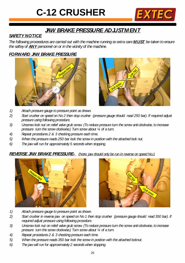
JAW BRAKE PRESSURE ADJUSTMENT
The following proceedures are carried out with the machine running so extra care MUST be taken to ensure the saftey of ANY personnel on or in the vicinity of the machine.
1) Attach pressure gauge to pressure point as shown.2) Start crusher on speed on No 2 then stop crusher (pressure gauge should read 250 bar). If required adjust
pressure using following procedure. 3) Unscrew lock nut on relief valve grub screw. (To reduce pressure turn the screw anti-clockwise, to increase
pressure turn the screw clockwise.) Turn screw about ¼ of a turn.4) Repeat procedures 2 & 3 checking pressure each time.5) When the pressure reads 250 bar lock the screw in position with the attached lock nut.6) The jaw will run for approximately 5 seconds when stopping.
SAFETY NOTICE
FORWARD JAW BRAKE PRESSURE
REVERSE JAW BRAKE PRESSURE- (Note: jaw should only be run in reverse on speed No.1
1) Attach pressure gauge to pressure point as shown.2) Start crusher in reverse jaw on speed on No 1 then stop crusher (pressure gauge should read 350 bar). If
required adjust pressure using following procedure. 3) Unscrew lock nut on relief valve grub screw. (To reduce pressure turn the screw anti-clockwise, to increase
pressure turn the screw clockwise.) Turn screw about ¼ of a turn.4) Repeat procedures 2 & 3 checking pressure each time.5) When the pressure reads 350 bar lock the screw in position with the attached locknut.6) The jaw will run for approximately 2 seconds when stopping.
Pressu
re Point
Pressure Point
Grub scre
w
Lock N
ut
Grub screw
Lock Nut
25

C-12 CRUSHER
MACHINE MAINTENANCEMaintenance is essential for ensuring the best possible performance from your Extec Crusher by reducing the chances of breakdowns.
WARNING:- The machine MUST be switched off and ignition keys removed BEFORE making any adjustments.
DO NOT stand on any part of the engine whilst operating or carrying out any maintenance on the machine.
All adjustments must ONLY be carried out by trained personnel.
All adjustments to modify hydraulic system must ONLY be carried out by trained Extec service engineers.
It is recommended that the following DAILY MAINTENANCE SCHEDULE be carried out:-
If necessary refill diesel tank.
Refill if necessary. (Refer to the engine manufacturers handbook for engine oil
specification).
Check fuel level
Check engine oil level
fuel levelfuel cap
oil cap
26

C-12 CRUSHER
DAILY MAINTENANCE SCHEDULE Cont.
Check service indicators on Air Cleaner. Regardless of condition of service indicator, remove elements from air cleaner as shown below and clean them using compressed air.(NOTE:- Service indicators are for showing when elements need to be replaced, not cleaned.)
Bleed diesel water trap.
Diesel Tap
2:- Unscrew nut to remove cover.
5:- Replace elements and rear cover after cleaning.
4:- Remove inner element3:- Loosen nut & Remove outer element
1:- Air cleaner inside of Power Unit
Securin
g nut
cover
Service indicator.
Check radiator water level & refill if necessary.
Radiato
r Cap
27

C-12 CRUSHER
WEEKLY MAINTENANCE SCHEDULEThe following weekly maintenance must be carried out to ensure the best performance from your Crusher:- STOP MACHINE AND REMOVE IGNITION KEY BEFORE CARRYING OUT ANY MAINTENANCE ON THIS MACHINE.
a) Check condition of conveyor belts, rollers and other moving parts.b) Clear any obstructions from the grizzly bars and crusher chamber.c) Check all bolts and panels are in place and secure.d) Clear any build up of dust from the oil cooler and radiator using compressed air.e) Check jaw plates for wear, and turn around or replace if necessary.f) Check condition of service indicators on hydraulic filters, water trap and air breather -
Replace if necessary.g) Examine toggle plate to make sure that it is free from cracks and other defects. -
Replace if necessary.h) Check toggle assembly for damage and clear any debris to ensure free movement of the
hydraulic cylinders.i) Check toggle clamping ram & link arm ram bearings for any damage or wear. -
Replace if necessary.j) Examine liner plates inside crusher chamber for wear - replace if necessary.k) Check jaw brake pressure - adjust if necessary (see page 25)l) Check emergency stops are working correctly (see page 9)m) Check crusher box front & rear beam fixing bolts - tighten if necessary.
Check feeder oil level and grease all bearings. Inspect - and adjust - all belt scrapers and sealing rubbers if necessary.
NOTE:- FULL movement of the jaw should be performed on a weekly basis, to ensure the adjustment wedge & clamping system are FREE moving and clear from any obstruction.
28

C-12 CRUSHER
WEEKLY MAINTENANCE SCHEDULE Cont.
CHECKING/CHANGING HYDRAULIC TANK AIR BREATHER:-
CHECKING CRUSHER BOX RETAINING BOLTS:-
1:- Raise cover plate and examine service indicator.
service indicator
3:- Check crusher box retaining bolts.
retain
ing bo
lt
lock nutNyloc nut
i) Release Nyloc nut, then the lock nut.ii) Tighten retaining bolt against crusher box.iii) Re-tighten lock nut.iv) Re-tighten Nyloc nut.
RETAINING BOLT ADJUSTMENT
2:- Remove oil filler plug. Refill using EP220 GEAR OIL until oil comes out of level hole.
CHECKING FEEDER OIL LEVEL:- (ALWAYS CHECK BOTH SIDES)
1:- Remove oil level plug. If oil trickles out, there is enough oil in feeder - if not, oil level
needs to be topped up.
filler plug
level plu
g
drain pl
ug
If the service indicator is green, it is time to replace the tank air breather. Simply remove air breather and replace with new one.
Note:- If Optional Oil Cooler is fitted, then it must be in the raised position & cover plate removed to access the Air Breather
29
C-12 CRUSHER
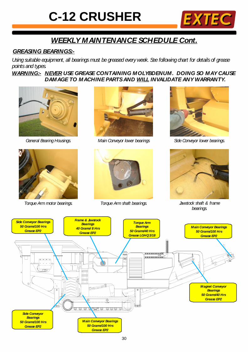
WEEKLY MAINTENANCE SCHEDULE Cont.GREASING BEARINGS:-Using suitable equipment, all bearings must be greased every week. See following chart for details of grease points and types.WARNING:- NEVER USE GREASE CONTAINING MOLYBDENUM. DOING SO MAY CAUSE
DAMAGE TO MACHINE PARTS AND WILL INVALIDATE ANY WARRANTY.
Magnet Conveyor Bearings
50 Grams/40 HrsGrease EP2
Main Conveyor Bearings50 Grams/100 Hrs
Grease EP2
Main Conveyor Bearings50 Grams/100 Hrs
Grease EP2
Side Conveyor Bearings50 Grams/100 Hrs
Grease EP2
Side Conveyor Bearings
50 Grams/100 HrsGrease EP2
Torque Arm Bearings
50 Grams/40 HrsGrease LGHQ3/18
Frame & Jawstock Bearings
40 Grams/ 8 HrsGrease EP2
General Bearing Housings. Main Conveyor lower bearings Side Conveyor lower bearings.
Torque Arm motor bearings. Torque Arm shaft bearings. Jawstock shaft & frame bearings.
30

C-12 CRUSHER
WEEKLY MAINTENANCE SCHEDULE Cont.
2:- Adjust if required.
3:- Refit clamp fixing screws
1:- Sealing rubber in correct position & condition
INSPECTING/ADJUSTING BELT SEALING RUBBERS:-
ADJUSTING BELT SCRAPER:-
If required, adjust head drum scraper by loosening bolts in rota springs, adjusting scraper and re-tightening bolts. (Both sides should be adjusted simultaneously).
31

C-12 CRUSHER
WEEKLY MAINTENANCE SCHEDULE Cont.Check service indicators on hydraulic filters when machine is running - (CHECKING CONDITION OF FILTER INDICATORS IS THE ONLY CHECK TO BE MADE WHEN MACHINE IS RUNNING). STOP MACHINE BEFORE REPLACING ELEMENTS.
4:- Replacing hydraulic water trap
CHANGING HYDRAULIC WATER TRAP.
NOTE.:- When the water trap is taken off, oil will spill out. Use a suitable container to catch any waste oil - expect between 3 and 5 litres. Replace water trap as shown.
CLEAN UP ANY OIL SPILLS AFTER PERFORMING THESE OPERATIONS
2:- Replace elements if service indicator is red
4:- Close and secure cover plate.
1:- Lift up cover & inspect service indicator
3:- Replace cap, ensuring "O"- ring is in place.
service
indicato
r
"O" ri
ng Note:- If Optional Oil Cooler is fitted, please refer to next page for maintenance instructions for hydraulic filters
32
C-12 CRUSHER
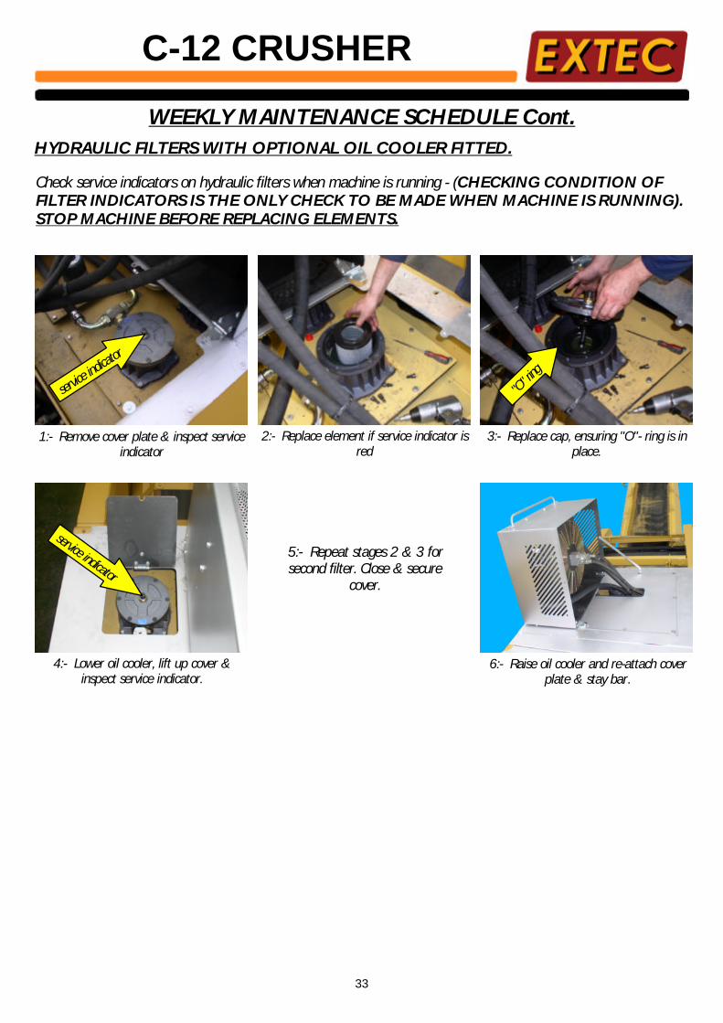
WEEKLY MAINTENANCE SCHEDULE Cont.
Check service indicators on hydraulic filters when machine is running - (CHECKING CONDITION OF FILTER INDICATORS IS THE ONLY CHECK TO BE MADE WHEN MACHINE IS RUNNING). STOP MACHINE BEFORE REPLACING ELEMENTS.
2:- Replace element if service indicator is red
4:- Lower oil cooler, lift up cover & inspect service indicator.
1:- Remove cover plate & inspect service indicator
3:- Replace cap, ensuring "O"- ring is in place.
service
indicato
r
"O" ri
ng
5:- Repeat stages 2 & 3 for second filter. Close & secure
cover.
6:- Raise oil cooler and re-attach cover plate & stay bar.
service indicator
HYDRAULIC FILTERS WITH OPTIONAL OIL COOLER FITTED.
33

C-12 CRUSHER
WEEKLY MAINTENANCE SCHEDULE Cont.TURNING / CHANGING JAW PLATES:-
6:- Fit new jaw plate, ensuring that all debris is cleaned from location slots.
1:- Remove wedge bolts and wedges from jawstock only
3:- Remove jaw plates using lifting hook & ropes provided with machine
and suitable lifting equip.
5:- Clean all debris from location blocks.
If, when examining liner plates, excessive wear is discovered, change liner plates by loosening all bolts and removing liner plate as shown. Refit new liner plates & Torque bolts to711Nm. Always use suitable lifting equipment to remove plates. DO NOT ATTEMPT TO REMOVE THEM BY HAND.
CHANGING CRUSHER BOX LINER PLATES:-
If, when examining jaw plates it is found that they are excessively worn they must be either turned or replaced. Jaw plates will wear more at the bottom of the crusher chamber, as this is where most of the crushing action takes place. The jaw plates can be turned around to maximise their useful life - to change or turn jaws proceed as follows:-
Do not allow jaw plate to become so badly worn that that the seats for the jawplate in crusher box or jawstock become excessively worn. This may result in the need for expensive repairs or new crusher box or jawstock.
2:- Push wear plate release lever to bring fixed wear plate forward
4:- Pull wear plate release lever to move wedge rams back into position
push
pull
location slot
locat
ion b
locklocation block
locatio
n slot
34

C-12 CRUSHER
MAINTENANCE SCHEDULE - EVERY 250Hrs
Every 250 hours, the following maintenance must be carried out in order to ensure the best performance and least possible amount of downtime from your machine.
i) Follow maintenance instructions laid out in engine manufacturers handbook..ii) Change the hydraulic water trap - REGARDLESS of condition of service indicator.iii) Change the hydraulic tank air breather - REGARDLESS of condition of service indicator.iv) Flush hydraulic system and change the hydraulic filters - REGARDLESS of condition of
service indicator.To flush hydraulic system, proceed as follows:-
a) Ensure all material has passed through the crusher and off the conveyor belts.b) Stop machine and replace hydraulic filters with 3 micron flushing filters.c) Fit new 10 micron water trap.d) Check condition of hydraulic tank air breather, if the service indicator is red, change it -
otherwise just clean all dust from the base of the filter. e) Run all systems for 4 hours with engine speed set to No.1 position (DO NOT
FEED MATERIAL INTO MACHINE DURING THIS OPERATION)f) Stop machine and replace flushing filters with new 25 micron hydraulic filters.
v) Check for leaks on hydraulic pipes.vi) Inspect condition of conveyor belts and tracking.vii) Inspect condition of all drums and rollers.viii) Inspect toggle clamping & link arm ram bearings.ix) Check drive belts for wear, swelling, softening & tension - Replace if necessary. (Note:- Tension
should remain constant during the belts working life and should not be Re-Tensioned.x) Clean out sediment bowl on fuel pre-filter. (Note:- When sediment bowl is cleaned out, the fuel
system will have to be re-primed, proceed as follows).
2:- Unscrew hand primer and pump up & down until a steady flow of fuel comes out of filters.
(there must be no bubbles coming through fuel line). Re-secure hand primer after use.
1:- Loosen screws on both fuel filters.
sediment bowl
35

C-12 CRUSHER
MAINTENANCE SCHEDULE - EVERY 1000HrsEvery 1000 hours, the following maintenance must be carried out:-
i) Repeat 250 hr maintenance schedule.ii) Change oil in vibrating feeder.iii) Change diesel filters.iv) Replace Toggle clamping & link arm ram bearings.v) Change oil in tracks.
To drain oil from the track gearbox, drive the machine until either one of the drainplugs is at the bottom of the gearbox. Remove drain plug and oil will drain out. Use asuitable container to collect waste oil - disposing of waste oil must be done in a mannerthat complies with any relevant legislation.To refill track gearbox with oil, drive machine until either one of the drain plugs is at the top- (See Photo). NOTE:- this will only be 1/4 turn of the track gearbox, DO NOT drivemachine any further until oil has been replaced in tracks. Remove both drain plugs as shownin the photographs below. Fill oil into the top drain plug until it starts to come out of theother drain plug. Replace both plugs BEFORE driving machine. Each track gearbox willhave to be done separately.
When changing oil in tracks, use EP90 Gear Oil.
Removing filler plug
Track gearbox in correct position to refill motor with oil.
Removing level plug
36

C-12 CRUSHER
TOGGLE PLATE REMOVAL / REPLACEMENTTo protect the crusher from the excessive loads generated by un-crushable objects, the Jawstock is fitted with overload protection device - "Toggle Plate". When the permissible loads are exceeded, the Toggle Plate will collapse from elastic buckling and the crusher will automatically shut down, providing a degree of protection to valuable machine components. When this happens, then clear any blockages from the machine and fit the replacement toggle in the following way.
View on hydraulic control box.
2:- Stop the machine as described on page 9.
solenoid
valve
1:- Close jaw up as described on page 19 to give a 30 to 40 mm gap.
3:- Using appropriate equipment support the toggle plate.
4 :- Remove toggle support arm tie bar & bush. (Note:- only one bolt shown)
toggle releasevalveaccu
mulator
6:- Restart machine as described on page 8and leave speed switch at position No.1(DO NOT OPERATE THE JAW LOCK).
relief va
lve
5 :- Screw in Relief Valve cartridge to disperse the accumulator pressure.
30 to 40 mmgap
G1
G2
G3
G1 G2 G3
G1 - CHARGE GAUGEG2 - CLAMP / ACCUM GAUGEG3 - WEDGE GAUGE
tie bar & bush
37

C-12 CRUSHER
TOGGLE PLATE REMOVAL / REPLACEMENT Cont.
7:- Unscrew locking screw.
locking
screw
8 :- Utilise screw as a valve handle & push valve handle to release toggle plt..
9:- Stop the machine as described on page 9.
10:- Lower existing toggle onto main conveyor. - remove & replace with new
toggle plate.
14:- Pull back the toggle release valve handle. This will then clamp the toggle
plate into position.
WARNING:- a) Ensure ALL personnel are clear of the machine BEFORE releasing the jawstock.b) Ensure that ALL guards are refitted and that the feeder, crusher and conveyor belts are empty BEFORE restarting machine.
15:- Remove valve handle and lock back into position shown above.
17:- Adjust to the required closed size setting as described on page 21.
relief valv
e
16:- Restart machine & press Jaw Lock ON button, screw out relief valve until
accumulator pressure gauge reads155 - 170 bar.
push
pull
12:- Raise new toggle plate into position.
13:- Replace toggle support arm tie bar & bush. (Note:- only one bolt shown)
tie bar & bush
Ignition Switch
11:- Examine toggle clamping & lift ram bearings for cracks & damage due to
toggle replacement. Replace if necessary.
Bearing
s
Bearings
Bearing
s
38
C-12 CRUSHER
TROUBLE SHOOTING GUIDEBelow is a list of some of the common problems that might occur on your machine. If these problems arise, carry out the checks listed.
PROBLEM SOLUTION
Engine losing power or hard to start.
Check air filter isn't blocked. Check diesel filter and sediment bowl.
Engine won't start or keeps shutting off.
Check that "Crusher" button is "on" in electrical box.Check fuel level.Check hydraulic oil level in tank.Check that there are no hydraulic pipes leaking.Check flywheel belt tension.Check engine speed switch is at No.2 position.Clean air filter, diesel filter & diesel sediment bowl.Check control pressure - see next page.
Crusher won't start.
Check hydraulic oil level in tank.Check that there are no hydraulic pipes leaking.Check flywheel belt tension.Check engine speed switch is at No.2 position.Clean air filter, diesel filter & diesel sediment bowl.
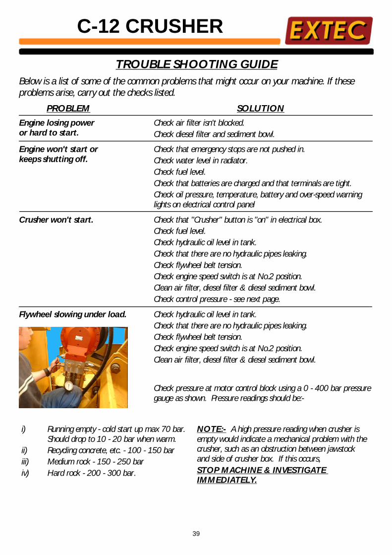
NOTE:- A high pressure reading when crusher is empty would indicate a mechanical problem with the crusher, such as an obstruction between jawstock and side of crusher box. If this occurs,STOP MACHINE & INVESTIGATE IMMEDIATELY.
Flywheel slowing under load.
Check that emergency stops are not pushed in.Check water level in radiator.Check fuel level.Check that batteries are charged and that terminals are tight.Check oil pressure, temperature, battery and over-speed warning lights on electrical control panel
Check pressure at motor control block using a 0 - 400 bar pressure gauge as shown. Pressure readings should be:-
i) Running empty - cold start up max 70 bar. Should drop to 10 - 20 bar when warm.
ii) Recycling concrete, etc. - 100 - 150 bariii) Medium rock - 150 - 250 bariv) Hard rock - 200 - 300 bar.
39

C-12 CRUSHER
TROUBLE SHOOTING GUIDE cont.
i) Check oil level in the hydraulic tank.ii) Check that Interlock and Track buttons are on.iii) Check remote handset is fully charged - Plug in Hard Wire Drive and try to move machine.iv) Check that all levers are in their central position and check if the crusher operates. If Crusher operates and levers are central but the machine still won't track, this may indicate an electrical problem. Contact Extec immediately.
Machine not tracking.
Check tank return pressure using a 0 - 10 bar pressure gauge - this should be not greater than 4 bar.
Check suction pressure using a 0 - 6 bar pressure gauge - this should be 1/2 bar min. - 1 1/2 bar max.
Check control pressure using a0 - 100 bar pressure gauge. This
should be 40 bar at all times.
Check webtec is fully open.Check pressure on at 4 station manifold using 0 - 250 bar pressure gauge - (See next page for detail)
Feeder not working.
Check clamp pressure is between 155 - 170bar.Check operation of toggle cylinders and ensure area is clear of debris..
"Knocking" noise coming from toggle.
Check flywheel alignment.Check ground conditions are firm and level.Check tracks are not slack. If the are, adjust as follows:-
Machine "Rocking" excessively.
2:- Fit grease adapter to grease point inside tracks
3:- Pump grease into tracks until they are tight.
1:- Remove access cover from side of track
PROBLEM SOLUTION
40

C-12 CRUSHER
TROUBLE SHOOTING GUIDE cont.
IF ANY PROBLEM PERSISTS AFTER CARRYING OUT THE RECOMMENDED SOLUTION, OR A PROBLEM ARISES THAT IS NOT ON THIS LIST, CONTACT EXTEC SERVICE DEPARTMENT FOR FURTHER ASSISTANCE. ADJUSTING PRESSURE SETTINGS OR REFILLING HYDRAULIC OIL ON THE MACHINE SHOULD ONLY BE DONE BY TRAINED EXTEC SERVICE ENGINEERS.
Main/Side/Magnet Conveyor belts jammed.
1:- Using jacking legs, lift machine off ground.
Test points are on manifold block on side of valve plate.
Check pressure at test points shown to check Feeder, Magnet, Side conveyor & Main conveyor using a 0 - 250 bar pressure gauge. Pressure readings when running empty should be:-
i) Feeder - Cold start = 100 bar - this should drop to 50 bar when warm.
ii) Magnet - 30 bariii) Side conveyor - 30 bariv) Main conveyor - 50 bar
Check belt tension.
Check that there is no build-up of material underneath machine. Clean under machine as shown in following photographs - if necessary.
2:- Ensure that locking pins andR-clips are fitted BEFORE cleaning
below machine
PROBLEM SOLUTION
Side c
on.
main co
n.
feeder
magnet
Auxili
ary
41

Extec Screens & Crushers LtdAm Frauenberg 236820 Oberaula
DeutschlandTelefon: +49 (0) 6628 9211-0Telefax: +49 (0) 6628 9211-11
Extec, IncPO Box 355Essington
PA, 19029-0355Tel: +1 610 521 1448
Tel: 1-800-44SCREENFax: +1 610 521 1863
Extec Screens & Crushers LtdHearthcote RdSwadlincote
Derbyshire DE11 9DUEngland
Tel: +44 (0) 1283 212121Fax: +44 (0) 1283 217342
42