Rethinking LTE Network Functions Virtualization -...
10
Rethinking LTE Network Functions Virtualization Muhammad Taqi Raza *§ , Dongho Kim † , Kyu-Han Kim † , Songwu Lu * and Mario Gerla * * University of California – Los Angeles (UCLA), † Hewlett Packard Enterprise Labs Email: * {taqi, slu, gerla}@cs.ucla.edu, † {dongho.kim, kyu-han.kim}@hpe.com Abstract—LTE Network Function Virtualization (LTE-NFV) scales user services in a low cost fashion by transforming the centralized legacy LTE Core architecture to a distributed architecture. This distributed architecture makes multiple in- stances of LTE Network Functions (NFs) and virtualizes them on commodity data-center network. The functionality of LTE-NFV architecture breaks however, since the distributed NF instances connected via unreliable IP links delay the execution of critical events. The failure of time-critical events results in users’ quality of service degradation and temporary service unavailability. In this paper, we propose a new way to virtualize LTE core network. We argue that logic-based NFs segregation should be done for NFV, instead of instance-based NFs segregation done in current NFV implementation. Our approach of ‘logic-based NFs segregation’ combines the logic of an event into a single NF, thus localizing the execution of critical events to one virtual machine. This way, only the localized entities exchange signalling messages, and the events do not experience large delays. We further reduce the delays by exploiting the parallelism in LTE network protocols; and partition these protocols such that their signalling messages run in parallel. In addition, we eliminate unnecessary messages to reduce the signalling overhead. We build our system prototype over OpenEPC LTE core network in virtualized platform. Our results show that we can reduce event execution time and signalling overhead up to 50% and 40%, respectively. I. I NTRODUCTION In this paper, we analyze the impact of virtualization on LTE Evolved Packet Core (EPC) functionality and service provisioning. We find that the legacy LTE EPC architecture is designed for fewer, powerful, and dedicated Network Func- tions (NFs). However, we argue that the functionality of EPC architecture breaks when this architecture is virtualized and scaled to thousands of NFs, where each NF is implemented in data-center network. Challenges and impact: We discover two major challenges in virtualized EPC (vEPC). 1. Virtualized network is not designed for LTE: LTE EPC is virtualized over data-center network which suffers from long queueing delays in switches, packet losses, timed out retransmissions, and out of order packets delivery [1]. Because of these characteristics, virtualized NFs (VNFs) implemented over commodity data-center network only provide flow level guarantees, whereas LTE standard requires packet level guar- antees (100ms and 300ms delays for voice and data packets, respectively) [2]. 2. LTE EPC is not designed for virtualized network: In legacy EPC, there are fewer NF boxes, which are connected through dedicated fiber links. The round-trip-time (RTT) over § Corresponding and student author. direct link is stable, and determines NF reachability and packet retransmission counters [3]. In vEPC however, some network signalling packets take longer over congested IP links, triggering unnecessary packet retransmissions at sender. The timeout and retransmission of signalling packets for one NF causes ‘time-out domino effect’ at the NFs that follow. This higher signalling failure rate while executing certain network events [4] have direct impact on user traffic (e.g. voice and data) continuity. We call these events ‘mission critical events’. Goal: We want to protect mission critical events from delay and failure. We identify three mission critical events; handover event during device mobility, paging event during device idle mode, and service request for gaining network resources. Since these three events cause 50% of LTE network signalling [5] [6], we aim to isolate these events from the vEPC to reduce network signalling load as well as execute critical events in a timely manner. Design: In legacy EPC, few dedicated NFs can handle millions of customers. In vEPC, whereas, thousands of NFs instances are initiated to handle same number of customers. These NF instances are distributed across data center network. The use of multiple NF instances in data-center achieves scalability, and provides simplified and inexpensive approach. However, it breaks the basic functionality of EPC when an event experiences long and unpredictable delays between these NFs. The distributed NF instances jeopardize the timely execution of events. In contrast, we took a holistic approach to design a robust and scalable EPC virtualization architecture. Our design theme is to perform logic based NFs segregation for an event, rather than the instance based NFs segregation in vEPC. In our design, we extract an event’s logic from each NF in the form of a module, and then assemble the extracted modules of the same event from several NFs into a Fat-proxy. This Fat-proxy – comprised of an event’s complete execution logic – acts as a standalone execution engine for that event. Let’s take an example of the “handover event” Fat-proxy that extracts mod- ules from the Mobile Management Entity (MME), P-Gateway (PGW), and Serving Gateway (SGW) NFs, and assembles them to make independent handover event facilitator. The concept of Fat-proxy or thick client is very useful in distributed community, where server delegates some processing logic to the client [7]. Our design is motivated from similar concept but under different setting; we want to make proxy a powerful component that completely executes a particular event. When vEPC receives an event request, it forwards the request to that event-specific Fat-proxy; it takes on the responsibility of executing that event and finally flushes the updated event status and device session information to vEPC. This way, all 978-1-5090-6501-1/17/$31.00 c 2017 IEEE
Transcript of Rethinking LTE Network Functions Virtualization -...

Rethinking LTE Network Functions VirtualizationMuhammad Taqi Raza∗§, Dongho Kim†, Kyu-Han Kim†, Songwu Lu∗ and Mario Gerla∗
∗University of California – Los Angeles (UCLA), †Hewlett Packard Enterprise LabsEmail: ∗{taqi, slu, gerla}@cs.ucla.edu, †{dongho.kim, kyu-han.kim}@hpe.com
Abstract—LTE Network Function Virtualization (LTE-NFV)scales user services in a low cost fashion by transformingthe centralized legacy LTE Core architecture to a distributedarchitecture. This distributed architecture makes multiple in-stances of LTE Network Functions (NFs) and virtualizes them oncommodity data-center network. The functionality of LTE-NFVarchitecture breaks however, since the distributed NF instancesconnected via unreliable IP links delay the execution of criticalevents. The failure of time-critical events results in users’ qualityof service degradation and temporary service unavailability.In this paper, we propose a new way to virtualize LTE corenetwork. We argue that logic-based NFs segregation should bedone for NFV, instead of instance-based NFs segregation donein current NFV implementation. Our approach of ‘logic-basedNFs segregation’ combines the logic of an event into a singleNF, thus localizing the execution of critical events to one virtualmachine. This way, only the localized entities exchange signallingmessages, and the events do not experience large delays. Wefurther reduce the delays by exploiting the parallelism in LTEnetwork protocols; and partition these protocols such that theirsignalling messages run in parallel. In addition, we eliminateunnecessary messages to reduce the signalling overhead. Webuild our system prototype over OpenEPC LTE core networkin virtualized platform. Our results show that we can reduceevent execution time and signalling overhead up to 50% and40%, respectively.
I. INTRODUCTION
In this paper, we analyze the impact of virtualization onLTE Evolved Packet Core (EPC) functionality and serviceprovisioning. We find that the legacy LTE EPC architectureis designed for fewer, powerful, and dedicated Network Func-tions (NFs). However, we argue that the functionality of EPCarchitecture breaks when this architecture is virtualized andscaled to thousands of NFs, where each NF is implementedin data-center network.Challenges and impact: We discover two major challengesin virtualized EPC (vEPC).1. Virtualized network is not designed for LTE: LTE EPCis virtualized over data-center network which suffers fromlong queueing delays in switches, packet losses, timed outretransmissions, and out of order packets delivery [1]. Becauseof these characteristics, virtualized NFs (VNFs) implementedover commodity data-center network only provide flow levelguarantees, whereas LTE standard requires packet level guar-antees (100ms and 300ms delays for voice and data packets,respectively) [2].2. LTE EPC is not designed for virtualized network: Inlegacy EPC, there are fewer NF boxes, which are connectedthrough dedicated fiber links. The round-trip-time (RTT) over
§Corresponding and student author.
direct link is stable, and determines NF reachability andpacket retransmission counters [3]. In vEPC however, somenetwork signalling packets take longer over congested IP links,triggering unnecessary packet retransmissions at sender. Thetimeout and retransmission of signalling packets for one NFcauses ‘time-out domino effect’ at the NFs that follow. Thishigher signalling failure rate while executing certain networkevents [4] have direct impact on user traffic (e.g. voice anddata) continuity. We call these events ‘mission critical events’.Goal: We want to protect mission critical events from delayand failure. We identify three mission critical events; handoverevent during device mobility, paging event during device idlemode, and service request for gaining network resources. Sincethese three events cause 50% of LTE network signalling [5][6], we aim to isolate these events from the vEPC to reducenetwork signalling load as well as execute critical events in atimely manner.Design: In legacy EPC, few dedicated NFs can handle millionsof customers. In vEPC, whereas, thousands of NFs instancesare initiated to handle same number of customers. These NFinstances are distributed across data center network. The useof multiple NF instances in data-center achieves scalability,and provides simplified and inexpensive approach. However,it breaks the basic functionality of EPC when an eventexperiences long and unpredictable delays between these NFs.The distributed NF instances jeopardize the timely executionof events.In contrast, we took a holistic approach to design a robust and
scalable EPC virtualization architecture. Our design theme isto perform logic based NFs segregation for an event, ratherthan the instance based NFs segregation in vEPC. In ourdesign, we extract an event’s logic from each NF in the formof a module, and then assemble the extracted modules of thesame event from several NFs into a Fat-proxy. This Fat-proxy– comprised of an event’s complete execution logic – acts asa standalone execution engine for that event. Let’s take anexample of the “handover event” Fat-proxy that extracts mod-ules from the Mobile Management Entity (MME), P-Gateway(PGW), and Serving Gateway (SGW) NFs, and assemblesthem to make independent handover event facilitator. Theconcept of Fat-proxy or thick client is very useful in distributedcommunity, where server delegates some processing logic tothe client [7]. Our design is motivated from similar conceptbut under different setting; we want to make proxy a powerfulcomponent that completely executes a particular event.When vEPC receives an event request, it forwards the requestto that event-specific Fat-proxy; it takes on the responsibilityof executing that event and finally flushes the updated eventstatus and device session information to vEPC. This way, all978-1-5090-6501-1/17/$31.00 c© 2017 IEEE

event execution logic remains local to one entity (Fat-proxy),thus solving issues incurred by distributed vEPC architecture,and keeping greater number of signalling messages awayfrom vEPC. Nevertheless, extracting event specific logicfrom multiple NFs is a challenge as we have to keep trackof different events, and resolve logic and data dependenciesamong those events.The second part of our design exploits the inherent parallelismin LTE network protocols by identifying and partitioning themutual exclusive logic of an event. In the “handover event”example, the MME logic can be split into two mutuallyexclusive partitions, which are able to run S1AP protocol op-erations and GTP protocol operations in parallel. Traditionally,these two types of operations execute one after the other. Bypartitioning, the network operations run in parallel and speed-up the execution of the event, thus mitigating the timeouts andthe need to re-transmit packets.Results: We show that our design (1) reduces more than 40%signalling load by skipping and parallelizing the messages fornetwork operations, (2) reduces up to 50% event executiontime, and (3) improves voice and data applications perfor-mance.
II. BACKGROUND: LTE ARCHITECTURE
LTE network consists of three main components; User Agent(UE), Evolved Node Base-station (eNodeB), and EvolvedPacket Core (EPC), as shown in Figure 1. These componentsare both logically and physically distributed. The eNodeBanchors as a radio interface between UE and EPC. EPCcommunicates with packet data networks in the outside worldsuch as the Internet, private corporate networks or the IP Mul-timedia Subsystem (IMS) and facilitates user communication.LTE EPC is comprised of a number of LTE Network Func-tions (NFs), which are Mobility Management Entity (MME),Home Subscriber Server (HSS), Serving Gateway (SGW),Packet Data Network Gateway (PGW), Policy and ChargingRules Function (PCRF), and a few others. These NFs handlecontrol-plane and data-plane traffic through separate networkinterfaces. As shown in Figure 1, control-plane traffic fromradio network is sent to MME (via S1-AP logical interface),whereas data-plane traffic is forwarded to SGW. MME acts asa central management entity that authenticates and authorizesUE, handles network events (such as device Attach, Handover,Service provisioning, and Paging events), and maintains SGWand PGW connections for data-plane traffic.
S1-AP MME HSS
Serving-Gateway PDN-Gateway
Data-PlaneControl-Plane
Evolved Packet Core (EPC)
Radio Network (eNodeBs)
UE
Figure 1: LTE architecture: an overview
EPC NFs are static in nature and are connected or chainedin a certain way to achieve desired LTE network functionali-
0 20 40 60 80 100 120
Attach/DetachActivation/Deactivation
Service Request/ReleasePaging
User MobilityService Awareness
No of events per subscriber during busy hour
Figure 2: Number of events per user during busyhours
MME1Legacy MME MME2 MME100
Figure 3: One legacy MME is de-composed into multiple virtualizedMME instances
ty/service. These NFs exchange a number of control messagesto execute a specific network event. For example, during deviceAttach event, MME obtains device security keys from HSS, au-thenticates the device, and creates device session informationat SGW and PGW. These SGW and PGW establish data bearerconnection with the device and configure specific QoS profile,thus registering the device with LTE network. The delay orfailure in one control-message results in complete event failure[8]. To mitigate these failure, the NFs – implemented overvendor specific software and hardware – guarantee messagelevel reliability and high availability.
III. MOTIVATION AND PROBLEM SCOPE
Instance-based vEPC implementation is not right: Tounderstand deployment strategies of virtualizing LTE by re-search and industry communities, we surveyed ETSI (theLTE standardized body) documents on NFV [9], white papersfrom industry [10], and recent work on LTE NFV (discussedin related work section VIII). We find that most of theseefforts talk about instance-based vEPC implementation, wherevEPC NFs (MME, SGW, PGW etc.) are installed as virtualmachine instances. In this paper, we stimulate the discussionthat although such contemporary NFV implementation (whichis highly distributed) suits the web-based applications’ needswell, it may not be a good choice for implementing vEPC.We address two major issues in the context of instance-basedvEPC implementation, i.e. (1) signalling storm during peakhours, and (2) timely execution of mission critical events.Controlling network signalling storm: LTE devices fre-quently interact with LTE network to execute their events.These events are Device Attach, Service Request and Release,Handover, Paging, Bearer Activation, Modification and Deac-tivation, Detach Request, and many others. Out of these events,some are executed more frequently than others. As shownin Figure 2, Handover event is executed at least 50 timesmore than device Attach incident during busy hours [5] [6].To execute one such event, different NF components interactwith each other and generate a greater number of signallingmessages. Some events produce more signalling messagesthan others. For example, one handover event can generateupto 32 signalling messages compared to paging event thatproduces only 6 signalling messages. When all events arecombined from all devices during busy hours, a signallingstorm is generated at EPC NFs. We are motivated to provide asolution that controls the signalling storm at LTE core withoutrestricting devices’ network access (the solution operationalLTE networks use to control signalling storm [11]).Signalling messages within vEPC incur latencies: LTEeNodeBs are connected with vEPC over a dedicated fiberlink. The latencies within vEPC are caused by VM hypervisor

as well as switching contention and port queuing [1], whichreach upto hundreds of milliseconds [12]. For each eventrequest from eNodeB, a greater number of signalling messagesexchanged among different VNFs in vEPC suffer networkdelays. For example, a single handover request message fromdevice generates up to 32 signalling messages (including thoserelated to SGW and MME relocation) within vEPC, andsuffer delays. Therefore, in this paper, we limit our scope tosignalling messages within vEPC, which are prone to higherlatencies as compared to fixed latencies over the eNodeB-vEPC fiber link.Administrating mission critical events: Our preliminarystudy on LTE operational network discloses that averageevents completion time at EPC is significantly high duringrush hours, reaching up to 3 seconds (as shown in Figure 4)1.This higher latency directly affects user QoS experience; fromVoice over LTE (VoLTE) call drop and voice jitter, to affectingTCP based services (refer to Table 6.1.7: Standardized QCIcharacteristics in [2] that provides latency requirements fordifferent applications). We are also motivated to provide timelyexecution of mission critical events during higher service loadat LTE NFs.Defining mission critical events: We classify those eventsas mission critical events whose delay or failure has a directimpact over ongoing user services (i.e. voice, data, and mul-timedia services). These events are:
• Handover event that ensures seamless user traffic flowduring user mobility.
• Paging event that wakes device from idle state whenvoice/data traffic is pending at LTE network.
• Service Request event that provides on-demand networkresources to device.
Interestingly, these 3 events make up 50% of all LTE networksignalling traffic [5]. By targeting these events, we not onlyensure timely execution of user service sessions but alsoaddress highly occurring network signalling messages.Assumptions: This work neither assumes special data centernetwork topology and high performance server boxes norrequires changes in LTE standard. We address timely executionof critical events on commodity data center network (withno dedicated/express links) while obeying LTE standard toprovide plug and play solution for any carrier network.
IV. CHALLENGES IN VIRTUALIZING LTE-EPC
We discover multiple challenges from our implementationof LTE-EPC virtualization, and from our study on LTE stan-dard documents and virtualized network infrastructure.
A. On data-center network characteristics
NFV infrastructure consists of commodity servers runningVirtualized Network Functions (VNFs) over cloud platforms.In contrast to legacy LTE NFs implementation, NFV im-plementation introduces a number of changes. First, VNFs
1We gather LTE traces at device and ignore radio retransmissions (at bothMAC and RLC LTE layers), and also excluded device and radio RTT fromresults.
00.20.40.60.8
1
400 900 1400 1900 2400 2900
CDF
Time (msec)Figure 4: Event completion time (average)during busy hours in operational EPC net-work
00.20.40.60.8
1
0 200 400 600 800 1000
CDF
RTT (sec)Figure 5: RTT fluctuation (average) invirtualized network
may be located over multiple hops unlike the traditional NFswhich are directly connected. Therefore, during congestion,long queueing delays in switches introduce high latencies [1][12]. Second, during high data-center utilization, packet lossprobability increases that can adversely affect traffic flows,where the loss of an ACK may cause TCP to perform a timedout retransmission. Third, data-center network traffic exploitsthe inherent multi-path nature of data-center networks [12]resulting in out of order packet delivery. Fourth, data-centernetwork is designed to meet application deadlines, whichprovide mechanisms to meet traffic flow deadlines (e.g. miceflows), rather than packet level guarantees [12].In short, data-center network is designed to meet Service LevelAgreement (SLA) by protecting execution bounds on trafficflows. However, in LTE, service guarantees are made by timelyexecution of mission critical events.
B. On inter-VNF delay
LTE-NFV framework provides the flexibility and networkscalability by decomposing original NFs into multiple VNFs[9]. In order to ramp up the original capacity of a NF,multiple VNF instances are needed. For example, hundreds(if not thousands) of MME-VNF instances are initiated overcommodity servers in order to facilitate 10 millions subscribersas supported by conventional MME function [13]. As shownin Figure 3, legacy MME is decomposed into multiple MMEinstances, where each MME holds the profiles of subset ofcustomers. These VNF instances are distributed within datacenter. Ideally, related EPC VNF instances (e.g. MME, SGW,PGW etc.) are placed within the same rack that eliminatesnetwork delays between two EPC NFs. However, during mo-bility, device switches from source eNodeB to target eNodeB– connected to different MME instance. As a result, thedevice session migrates from its source MME to target MMEduring handover. Thereafter, new serving MME and rest of oldserving EPC NFs (e.g. SGW and PGW etc.) end up residingat different racks. Now network delays play important role ontimely execution of network signalling messages. We find thatLTE-NFV framework is not able to cope with varying delaysamong different VNF instances because of following reasons:
Expiry of a timer at any NF may lead to event failure:LTE was designed for fewer EPC NFs which are directlyconnected over dedicated fiber link. Therefore, in legacy LTEnetwork, the variation in RTT values is negligible. This moti-vates LTE network designer to use RTT for two purposes (1)path management, and (2) calculating message retransmissiontimer between a pair of EPC NFs.

Path management: As a matter of fact, all EPC NFs and theconnection between them must always be active to serve users.To determine that a peer NF is active, the NFs exchange echo-request and echo-response messages [3]. This exchange of theecho-request and echo-response messages between two NFsallows for quick path failure detection [3].Retransmission timer: Echo-request and echo-response alsohelp in calculating packet retransmission time at EPC NF. Re-transmission timer is calculated based on RTT measurements(i.e. time difference between echo-request and echo-response)[3]. Although, such timer value incorporates arbitrary RTTvalue delays, it does not include larger RTT value variationsbecause network communication delay does not vary fordirectly connected legacy LTE NFs.However, virtualized EPC implementation needs to addresssignificant RTT variations. Data-center network’s link redun-dancy provides multiple paths for each distributed pair of NF[12]. This means echo-request and echo-response packets maytraverse through two different paths for each RTT calculation.This can potentially cause a significant variation betweentwo subsequent RTT measurement readings. To make thingsworse, data-center network congestion can cause RTT spikesto tens of milliseconds making EPC retransmission timercalculation even harder. Figure 5 shows variation of RTTvalues in a virtualized network [12]. RTT varies from fewmicroseconds to 1000 microseconds under normal networkload. This 1000X RTT difference converts into hundreds ofdifferent timer values.When a NF selects smaller timer value based on smallerRTT, the signalling messages from that NF are unnecessarilyretransmitted, as shown in Figure 6. Unnecessary signallingmessages retransmission lead to overall delay in event exe-cution; and expiry of event-timer running at device results inevent failure.
Expiration of a timer has a domino effect: For one eventexecution, multiple EPC NFs are chained such that one NFoutput is an input of second NF, and so on. For example, inhandover event execution, signalling messages are exchangedbetween 5 different NFs (i.e. source MME, source SGW, targetMME, target SGW, and PGW). Each pair of NF is runninga different retransmission timer value. When one timer valueexpires, it produces a domino effect that causes expiration ofpreceding NF timer. This has been shown in Figure 7, wheresource MME sends handover signalling message (e.g. ForwardRelocation Request message) to a target MME. Target MMEsends another handover message (e.g. Create Session Requestmessage) to SGW. Even in the presence of mild networkcongestion, the response from SGW is delayed and the timerat target MME expires. Because source MME is waiting fora response from target MME, eventually the timer value atsource MME expires. This can potentially create a dominoeffect to chained NFs for handover event execution.In short, EPC by design is not only sensitive to networkdelays but also does not tolerate even mild delay variance.It is challenging to provide both constant and smaller networkdelays in virtualized data-center network, where packets may
S-GW P-GW
Echo requestEcho response
Signaling messageMessage response delayed
X
XMessage response delayed
Leads to event failure
RTT
Signaling message
Figure 6: Signalling messages expire pre-maturely when a timer based on RTTvalue is too short
S-GW MMEtarget
Handover messageHandover message response delayed
XTimer expires
Delay between two NFs has domino effect to all other chained NFs
MMEsource
Handover message
Timer expires
Figure 7: Expiry of timer between twoNFs has a domino effect that leads to anevent failure
face network congestion and take multiple packet traversalpaths, which were not the case in legacy EPC.We should also clarify that engineering efforts, such as off-loading traffic from busy servers, do not work for vEPC. Thisis mainly because current data-center networks are designedusing web service applications in mind; whereas vEPC (byEPC design rule) requires that all active user sessions remainwithin same EPC NFs, otherwise the GTP-tunnel [14] betweentwo LTE NFs breaks and incurs further delays.
V. SYSTEM DESIGN
Design overview: The comparison of our design withcontemporary EPC architectures is shown in Figure 8. Net-work Functions (NFs) pass messages among one another, andperform operations to execute an event. We see in Figure 8that the legacy LTE EPC has dedicated NFs (for example,MME, SGW, and PGW), connected via fiber links. Hence themessage passing between NFs experience minimum delays,and these NFs almost always guarantee event execution. Aswe move from legacy EPC to Virtualized EPC network, wesee multiple instances of the same NFs distributed in data-center networks and joined via unreliable IP links. TheseNFs in vEPC are designed to support few thousands usersas compared to million of users being supported by legacynetwork; yet vEPC NFs are simple, scalable, and provideplug and play solution to the service providers. However,the main culprit of EPC virtualization is high delay betweenconsecutive NFs for a single event. When delay guarantees arenot provided, the system fails to execute events and provideservices.First contribution: We propose an alternative approach forEPC virtualization that solves the above problems. We baseour design on logic based NFs segregation instead of Instancebased NFs segregation for vEPC. For every critical event, weextract the logic of that event from each NF in the form of amodule. Then we assemble the event-based modules extractedfrom all NFs into a Fat-proxy as shown in Figure 8. ThisFat-proxy acts as a NF for that event. Note that we makeFat-proxys only for three critical events (handover, paging,and service request), since we have already established thatthese critical events constitute 50% of the control signallingtraffic. The advantage of extracting logic based modules andassembling them into a Fat-proxy is three-fold. First, the Fat-proxy acts as a single NF and is made to handle only asingle type of event. This reduces delays and avoids timeouts.Second, huge storm of critical events’ signalling traffic isdiverged from the EPC to the Fat-proxy, and the EPC can
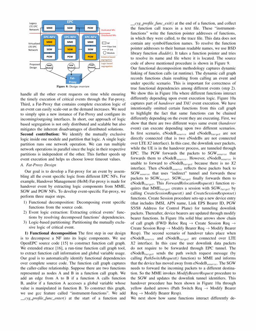
EPC
MME SGW PGW
EPC-NFVMME
SGW
PGW
EPC-NFVMME
SGW
PGW
EPC-NFVMME
SGW
PGW
PGWModule
SGWModule
MMEModule
Fat-Proxy
Legacy LTE EPC Network
Virtualized LTE EPC Network
Proposed Design
Dedicated NFs
Distributed NFs
Instance based segregation
Logic based segregation
NFFiber linkIP linkModule
Figure 8: Design overview
handle all the other event requests on time while ensuringthe timely execution of critical events through the Fat-proxy.Third, a Fat-Proxy that contains complete execution logic ofan event can easily scale-out as the demand increases. We needto simply spin a new instance of Fat-Proxy and configure itsincoming/outgoing interfaces. In short, our approach of logicbased segregation is not only distributed and scalable but alsomitigates the inherent disadvantages of distributed solutions.Second contribution: We identify the mutually exclusivelogic inside one module and partition that logic. A single logicpartition runs one network operation. We can run multiplenetwork operations in parallel since the logic in their respectivepartitions is independent of the other. This further speeds upevent execution and helps us choose lower timeout values.A. Fat-Proxy Design
Our goal is to develop a Fat-proxy for an event by assem-bling all the event specific logic from different EPC NFs. Forexample, Handover Management (HoM) Fat-proxy is made forhandover event by extracting logic components from MME,SGW and PGW NFs. To develop event-specific Fat-proxy, weperform three major steps.
1) Functional decomposition: Decomposing event specificfunctions from the source code.
2) Event logic extraction: Extracting critical events’ func-tions by resolving decomposed functions’ dependencies.
3) Logic-based partitioning: Partitioning the mutually exclu-sive logic of critical event.
1) Functional decomposition The first step in our designis to decompose a NF into its logic components. We useOpenEPC source code [15] to construct function call graph.We extended etrace [16], a run-time function call graph tool,to extract function call information and global variable usage.Our goal is to automatically identify functional dependenciesover complete source code. The function call graph capturesthe caller-callee relationship. Suppose there are two functionsrepresented as nodes A and B in a function call graph. Weadd an edge from A to B if a function A calls functionB, and/or if a function A accesses a global variable whosevalue is manipulated in function B. To construct this graph,we use gcc feature called “instrument-functions”. We add
cyg profile func enter() at the start of a function and
cyg profile func exit() at the end of a function, and collectthe function call traces in a text file. These “instrument-functions” write the function pointer addresses of functions,in which they were called, to the trace file. This data does notcontain any symbol/function names. To resolve the functionpointer addresses to their human readable names, we use BSDlibrary function dladdr(). It takes a function pointer and triesto resolve its name and file where it is located. The sourcecode of above mentioned procedure is shown in Figure 9.Our functional decomposition methodology captures dynamiclinking of function calls (at runtime). The dynamic call graphrecords functions chain resulting from calling an event andunder specific scenario. This is important for correctness oftrue functional dependencies among different events (step 2).We show this in Figure 10a where different functions interactdifferently depending upon event execution logic. Figure 10acaptures part of handover and TAU event execution. We haveintentionally omitted certain functions from this call graphto highlight the fact that same functions can be chaineddifferently depending on the event they are executing. First, weshow that there are two different ways same event (handoverevent) can execute depending upon two different scenarios.In first scenario, eNodeBsource and eNodeBtarget are notdirectly connected (that is two eNodeBs are not connectedover LTE X2 interface). In this case, the downlink user packets,while the UE is in the handover process, are tunneled throughEPC. The PGW forwards the packets to SGWsource thatforwards them to eNodeBsource. However, eNodeBsource isunable to forward to eNodeBtarget because there is no X2interface. Then eNodeBsource reflects these packets back toSGWsource that uses “indirect” tunnel and forwards thesepackets to SGWtarget. SGWtarget finally forwards them toeNodeBtarget. This ForwardRelocationRequest() function re-quires that MMEtarget creates a session with SGWtarget bycalling CreateSessionRequest() and CreateSessionResponse()functions. Create Session procedure sets-up a new device entry(that includes IMSI, APN name, Link EPS Bearer ID, PGWS5/S8 Address for Control Plane) for tunneling downlinkpackets. Thereafter, device bearers are updated through modifybearer functions. In Figure 10a solid blue arrows show chainof call graph (FWD Reloc Req → Create Session Req →Create Session Resp → Modify Bearer Req → Modify BearerResp). The second scenario of handover takes place wheneNodeBsource and eNodeBtarget are connected over LTEX2 interface. In this case the user downlink data packetsdo not require to be forwarded through EPC tunnel. TheeNodeBtarget sends the path switch request message (bycalling PathSwitchRequest() function) to MME and informsthat the device has moved away from eNodeBsource. The SGWneeds to forward the incoming packets to a different destina-tion. So the MME invokes ModifyBearerRequest procedure tothe SGW and updates the downlink tunnel identifiers. Thishandover procedure has been shown in Figure 10a throughyellow dashed arrows (Path Switch Req → Modify BearerReq → Modify Bearer Resp).We next show how same functions interact differently de-
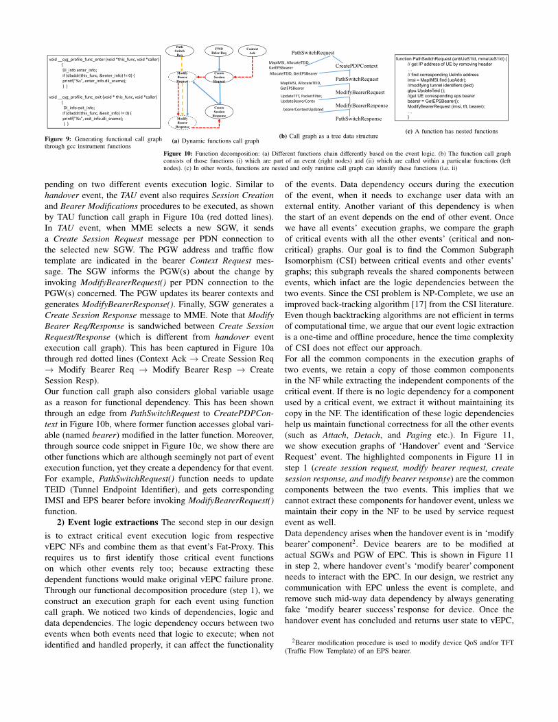
void __cyg_profile_func_enter (void *this_func, void *caller){Dl_info enter_info;if (dladdr(this_func, &enter_info) != 0) {printf("%s", enter_info.dli_sname);} }
void __cyg_profile_func_exit (void * this_func, void *caller){
Dl_info exit_info;if (dladdr(this_func, &exit_info) != 0) {printf("%s", exit_info.dli_sname);} }
Figure 9: Generating functional call graphthrough gcc instrument functions
Create Session Request
Modify Bearer
Request
Modify Bearer
Response
Create Session
Response
FWD Reloc Req
Path Switch
Req
Context Ack
(a) Dynamic functions call graph
PathSwitchRequest
CreatePDPContext
PathSwitchRequest
ModifyBearerRequest
ModifyBearerResponse
PathSwitchResponse
AllocateTEID, GetEPSBearer
MapIMSI, AllocateTEID,GetEPSBearer
MapIMSI, AllocateTEID,GetEPSBearer
UpdateTFT, PacketFilter,UpdateBearerContx
bearerContextUpdated
(b) Call graph as a tree data structure
function PathSwitchRequest (enbUeS1Id, mmeUeS1Id) {// get IP address of UE by removing header…// find corresponding UeInfo addressimsi = MapIMSI.find (ueAddr);//modifying tunnel identifiers (teid)gtpu.UpdateTeid ();//get UE corresponding eps bearerbearer = GetEPSBearer();ModifyBearerRequest (imsi, tft, bearer);…}
(c) A function has nested functions
Figure 10: Function decomposition: (a) Different functions chain differently based on the event logic. (b) The function call graphconsists of those functions (i) which are part of an event (right nodes) and (ii) which are called within a particular functions (leftnodes). (c) In other words, functions are nested and only runtime call graph can identify these functions (i.e. ii)
pending on two different events execution logic. Similar tohandover event, the TAU event also requires Session Creationand Bearer Modifications procedures to be executed, as shownby TAU function call graph in Figure 10a (red dotted lines).In TAU event, when MME selects a new SGW, it sendsa Create Session Request message per PDN connection tothe selected new SGW. The PGW address and traffic flowtemplate are indicated in the bearer Context Request mes-sage. The SGW informs the PGW(s) about the change byinvoking ModifyBearerRequest() per PDN connection to thePGW(s) concerned. The PGW updates its bearer contexts andgenerates ModifyBearerResponse(). Finally, SGW generates aCreate Session Response message to MME. Note that ModifyBearer Req/Response is sandwiched between Create SessionRequest/Response (which is different from handover eventexecution call graph). This has been captured in Figure 10athrough red dotted lines (Context Ack → Create Session Req→ Modify Bearer Req → Modify Bearer Resp → CreateSession Resp).Our function call graph also considers global variable usageas a reason for functional dependency. This has been shownthrough an edge from PathSwitchRequest to CreatePDPCon-text in Figure 10b, where former function accesses global vari-able (named bearer) modified in the latter function. Moreover,through source code snippet in Figure 10c, we show there areother functions which are although seemingly not part of eventexecution function, yet they create a dependency for that event.For example, PathSwitchRequest() function needs to updateTEID (Tunnel Endpoint Identifier), and gets correspondingIMSI and EPS bearer before invoking ModifyBearerRequest()function.
2) Event logic extractions The second step in our designis to extract critical event execution logic from respectivevEPC NFs and combine them as that event’s Fat-Proxy. Thisrequires us to first identify those critical event functionson which other events rely too; because extracting thesedependent functions would make original vEPC failure prone.Through our functional decomposition procedure (step 1), weconstruct an execution graph for each event using functioncall graph. We noticed two kinds of dependencies, logic anddata dependencies. The logic dependency occurs between twoevents when both events need that logic to execute; when notidentified and handled properly, it can affect the functionality
of the events. Data dependency occurs during the executionof the event, when it needs to exchange user data with anexternal entity. Another variant of this dependency is whenthe start of an event depends on the end of other event. Oncewe have all events’ execution graphs, we compare the graphof critical events with all the other events’ (critical and non-critical) graphs. Our goal is to find the Common SubgraphIsomorphism (CSI) between critical events and other events’graphs; this subgraph reveals the shared components betweenevents, which infact are the logic dependencies between thetwo events. Since the CSI problem is NP-Complete, we use animproved back-tracking algorithm [17] from the CSI literature.Even though backtracking algorithms are not efficient in termsof computational time, we argue that our event logic extractionis a one-time and offline procedure, hence the time complexityof CSI does not effect our approach.For all the common components in the execution graphs oftwo events, we retain a copy of those common componentsin the NF while extracting the independent components of thecritical event. If there is no logic dependency for a componentused by a critical event, we extract it without maintaining itscopy in the NF. The identification of these logic dependencieshelp us maintain functional correctness for all the other events(such as Attach, Detach, and Paging etc.). In Figure 11,we show execution graphs of ‘Handover’ event and ‘ServiceRequest’ event. The highlighted components in Figure 11 instep 1 (create session request, modify bearer request, createsession response, and modify bearer response) are the commoncomponents between the two events. This implies that wecannot extract these components for handover event, unless wemaintain their copy in the NF to be used by service requestevent as well.Data dependency arises when the handover event is in ‘modifybearer’ component2. Device bearers are to be modified atactual SGWs and PGW of EPC. This is shown in Figure 11in step 2, where handover event’s ‘modify bearer’ componentneeds to interact with the EPC. In our design, we restrict anycommunication with EPC unless the event is complete, andremove such mid-way data dependency by always generatingfake ‘modify bearer success’ response for device. Once thehandover event has concluded and returns user state to vEPC,
2Bearer modification procedure is used to modify device QoS and/or TFT(Traffic Flow Template) of an EPS bearer.

Modify Bearer Res.Handover RequestHandover Required
Handover Command
Create Session Req.Create Session Resp.Creat. Indirct Tunnel
FWD Relocation
eNodB Status Trans.
Delete Session
Modify Bearer Req.
Context Access Not.
Delete Tunnel Release Data FWD Release Context
Start
EndNAS Service RequestInitial Context Req.
Create Session Req.Create Session Resp.Authentication Res.
Authentication Req
Initial Context Setup
Modify Bearer Req.
Start
Modify Bearer Res.
EndDL/UL Data-Start
(a) Handover Event
(b) Service Request Event (c) TAU Event
Context Req.…
…
EPC1
2
3
Figure 11: Identifying logic dependencies through Common Subgraph Isomorphism(ICS) and data dependencies through protocol analysis
the vEPC runs the actual ‘modify bearer’ request. It is possiblethat such bearer modification step fails (e.g. one of SGW orPGW fails), even though the device is already notified of asuccessful bearer modification. This is not a problem becausethe vEPC can simply initiate the re-attach event in this case.In Figure 11 step 3, we also see the second kind of datadependency between the handover event and the tracking areaupdate (TAU) event. The TAU event waits for the handoverevent to finish before it starts its execution. Such a dependencybetween two events is mitigated when events execute inblocking mode (see Figure 5.1.3.2.2.7.1: EMM main states inthe UE [8]. The Figure shows that no other event can executeif one event is being executed).We follow the above procedure for the other two criticalevents, i.e. service request event and paging event. At thisstep, we have working Fat-Proxy for all three critical events.
3) Network protocols’ logic-based partitioning The thirdand last step is about optimizing Fat-proxy execution (i.e. oursecond contribution). We recall that message execution delayof a critical event disrupts timely execution of that event; andto be worse its failure aborts the critical event procedure.Therefore, there is a need to speed-up event execution byexecuting some messages in parallel. We propose networkprotocols’ logic-based partitioning to achieve this goal. Wepartition the mutually exclusive logic of different protocolsin a module (module is event-based logic from one NF). Weidentify the opportunity of logic-based partitioning throughanalysis of these standardized protocols.We explain this through handover event example. The han-dover event triggers coordination between a series of NFs(MME, SGW, and PGW). Such coordination takes placebetween different NFs within EPC, and between EPCs and theradio network (eNodeB). The MME NF requests eNodeB toestablish secure radio connection with UE, instructs eNodeBto establish device context, initiates the connection betweenSGW NF for user uplink/downlink traffic, and many more.The signalling messages exchange between MME and eNodeBare carried out by S1AP protocol, while the communicationbetween MME and other NF (i.e. SGW) is carried out usingGTP protocol. The legacy EPC infrastructure tightly couplesS1AP protocol with other protocols like GTP protocol inMME. However, these protocols are designed for differentpurposes and their messages do not interleave with each other.The MME’s interaction with eNodeB via S1AP protocol is mu-
eNodeB S-MME T-MME S-SGW T-SGWHandover required FWD Allocation
Create Session Req.Handover RequestSession ResponseHandover ACK
FWD Allocation Resp.Create Indirect data FWD tunnelHandover Command
eNodeB StatusTransfer
FWD tunnel resp.
Those S1AP Messages ( ) and GTP messages ( ) which are executed in parallelFigure 12: Concurrent execution of messages: S1AP messages (shown as dotted linearrows) and GTP messages (shown as dashed line arrows) are executed in parallel toeach other. Sequence execution of messages (S1AP and GTP) are shown as solid line
tually exclusive to MME’s communication with SGW throughGTP protocol. Therefore, we partition the logic of S1AP,MME core function, and GTP protocols inside MME NF’smodule. This design choice results in faster communicationbetween eNodeB and vEPC using S1AP protocol, and betweenvEPC’s MME and SGW NFs using GTP protocol, even duringdata-center network congestion.A protocol defines message exchange procedure betweendifferent entities. Figure 12 shows subset of these mes-sages exchanged between EPC NFs during handover event.MMEserving (S-MME) receives Handover Required messagefrom eNodeB and triggers Forward Allocation message toMMEtarget (T-MME). After receiving, T-MME sends “Cre-ate Session Request” to SGWtarget (T-SGW). On successfulsession response from T-SGW, T-MME sends Handover Ac-knowledgement to eNodeB. Note that the direction of “CreateSession Request” and “Handover Request” messages are oppo-site (both messages are sent simultaneously), where former is apart of GTP protocol, and the latter is a part of S1AP protocol.The messages shown as dotted and dashed lines in Figure12 are executed in parallel. The simultaneous transmissionof these messages is possible since their respective protocolsare mutually exclusive. We accelerate handover event (whichwe chose as an example) by identifying the protocol levelmodularity in a NF and execute their corresponding messagesin parallel. We find that in most network events, there exists40% to 60% messages that can be executed concurrently tosignificantly improve the network performance.There is a chance that concurrent message execution may failand this failure may provide inconsistent view of networkstates to eNodeB. For example, on receiving the “HandoverRequest” message from T-MME, the eNodeB believes thatthe T-MME has successfully established the device connectionwith T-SGW. But eNodeB’s network states may get incorrect,in case T-MME has failed to establish device session withT-SGW. To handle such network state inconsistencies, wepropose transaction rollback by sending network failure mes-sage. As stated earlier, message execution failure at any stepterminates the entire handover process, therefore, by sendinga failure message (even at later step) to eNodeB addressesany inconsistency previously caused by concurrent messageexecution. We should highlight that network states withindifferent NFs of vEPC remain consistent because handoverevent executes in blocking mode. Moreover, we partition onlymutually exclusive messages of two different protocols. Ourdesign is robust where parallel execution of these messagesproduce the same result as their sequential execution.
VI. SYSTEM IMPLEMENTATIONOur system implementation consists of OpenEPC LTE im-
plementation and LTE EPC NFs virtualization.OpenEPC LTE deployment: Our test-bed consists of LTEeNodeB (nanoLTE Access Point [18]), OpenEPC softwareEPC platform [15], and Samsung S6 smartphones. The eN-odeB is a 3GPP Release 9 compliant LTE small cell on700 MHz band. Considerable effort, involving code mod-ifications to OpenEPC components, is made to integrateeNodeB (closed-source) with EPC to ensure interoperabilitywith commercially available LTE clients (i.e. Samsung S6smartphones). Our EPC network consists of MME, HSS,PCRF for control plane, and SGW and PGW for data planefunctions. In addition, the Internet gateway provides connec-tivity to the Internet. Samsung S6 smartphones use USIMcards programmed with the appropriate identification nameand secret code to connect with eNodeB. Since eNodeB andthe device communicate on T-Mobile’s licensed band, we usecustom built frequency converters. These converters convertthe frequency in both downlink and uplink from 700 MHz to2.6 GHz, where we have an experimental license to conductover the air experiments.For the evaluation of our second design choice (protocols’logic partitioning), where S1AP-MME simultaneously com-municates with S1AP-eNodeB and SGW, we require changesat eNodeB-S1AP. Because our eNodeB is closed-source, weuse device emulation provided by OpenEPC. The OpenEPCprovides client-Alice module that emulates user device andeNodeB and interacts with EPC NFs. The client-Alice modulehas basic S1-AP functionality, enough to show performanceimprovement when protocols’ logic partitioning is used.Virtualizing LTE EPC: After LTE testbed deployment, wevirtualize EPC NFs. EPC virtualization includes deploymentof decomposed EPC NFs over VMs, and exposing them toreal LTE traffic load.EPC’s NFs decomposition and placement: We virtualize EPCNFs over vMware’s vSphere, which is a server virtualizationplatform with consistent management. We first decomposeOpenEPC into a number of LTE NFs (i.e. MME, SGW, PGW,HSS, and PCRF). To implement an event-specific Fat-proxy,we first identify the Fat-proxy’s logic based on the event’s statetransition diagram (as shown in Figure 11). We then traversethrough OpenEPC NFs source code to locate that implemen-tation logic. This event logic is deployed on a separate VM(after extracting/copying from OpenEPC NFs) and we call itthat event’s Fat-proxy. Now this Fat-proxy’s VM acts as stand-alone NF. Thereafter, we configure the interfaces for all virtualNFs (LTE NFs as well as Fat-proxy) by changing OpenEPCboot process (init) so that the OpenEPC can discover installedFat-proxies at start-up and allows relaying packets to and fromthese virtual NFs (VNFs).During actual execution of a critical event, OpenEPC storesmost of the information needed by a NF (such as device states)in a back-end database. To reduce the overhead of Fat-proxycommunicating with the database back-and-forth, we duplicatethe device states at Fat-proxy when the critical event triggers.
We gather results by changing testbed configurations for twodifferent settings: (a) placing the VNFs (with no Fat-proxy)over different servers, which are then connected throughnetwork tunnel, and (b) installing the Fat-proxy VNF withinone server.Considering real data-center network loads: Because researchlab’s testbed environment does not (a) add round trip time todata-center network (b) consider dynamic loads at servers (c)take data-center network congestion into account; we considerdata-center network performance metrics while compiling ourresults. We parsed system logs provided by HP Helion cloudinfrastructure and gather inter-data-center network latencymetrics. We measure round trip time from query enteringand exiting the data-center network. We understand, it ischallenging to precisely find the root cause of latency for eachquery [19]. Therefore, we apply moving average to cancelrandom variation in our result.
VII. EVALUATION AND RESULTS
We evaluate our design based on following aspects: (1)controlling signalling storm, (2) timely execution of missioncritical events, and (3) performance impact. We compare ourapproach against contemporary instance based vEPC LTEdesign, which is not only deployed by a number of networkoperators [9], but also discussed in recent research papers[20]–[22]. We run our tests on a local network of servers with10-core Intel Xeon E5 - 2650 v3 processors at 2.3Ghz, 25MBcache size, and 16GB memory. We build our prototype andtested it using real smartphones (Samsung S6 smartphones)and device emulation mode of OpenEPC. To consider realoperator network scenario, we use a network trace as our inputpacket stream; results are representative of tests we run usingthese traces.
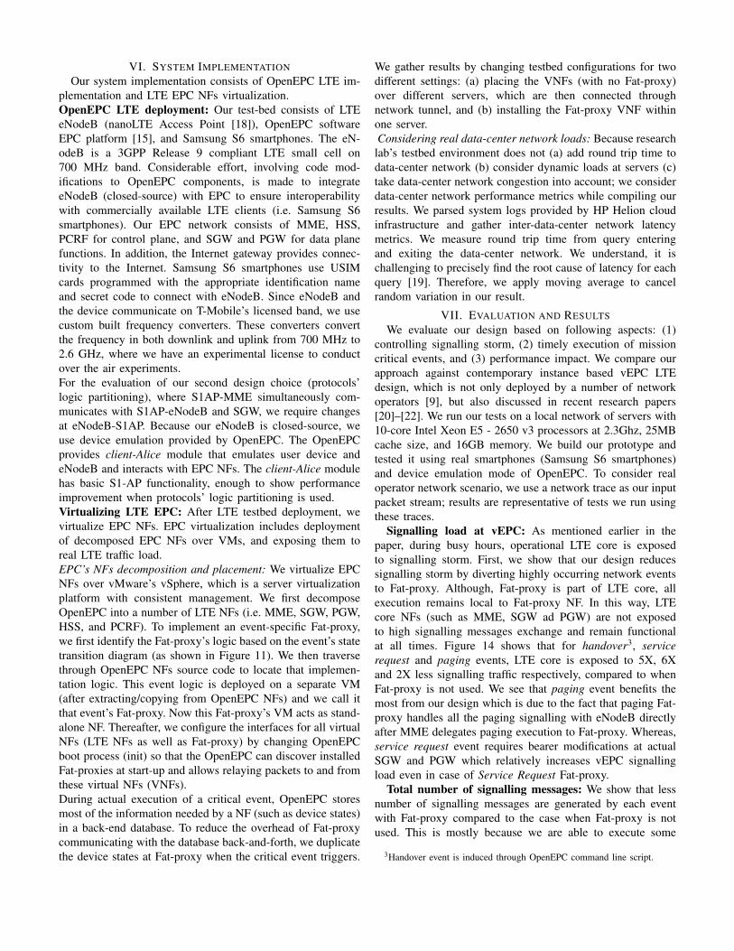
Signalling load at vEPC: As mentioned earlier in thepaper, during busy hours, operational LTE core is exposedto signalling storm. First, we show that our design reducessignalling storm by diverting highly occurring network eventsto Fat-proxy. Although, Fat-proxy is part of LTE core, allexecution remains local to Fat-proxy NF. In this way, LTEcore NFs (such as MME, SGW ad PGW) are not exposedto high signalling messages exchange and remain functionalat all times. Figure 14 shows that for handover3, servicerequest and paging events, LTE core is exposed to 5X, 6Xand 2X less signalling traffic respectively, compared to whenFat-proxy is not used. We see that paging event benefits themost from our design which is due to the fact that paging Fat-proxy handles all the paging signalling with eNodeB directlyafter MME delegates paging execution to Fat-proxy. Whereas,service request event requires bearer modifications at actualSGW and PGW which relatively increases vEPC signallingload even in case of Service Request Fat-proxy.
Total number of signalling messages: We show that lessnumber of signalling messages are generated by each eventwith Fat-proxy compared to the case when Fat-proxy is notused. This is mostly because we are able to execute some
3Handover event is induced through OpenEPC command line script.

0
500
1000
1500
2000
2500
3000
3500N
o. o
f sig
nalli
ng m
essa
ges Handover w/oFat-Proxy
Handover Fat-proxyPaging w/o Fat-ProxyPaging Fat-ProxySR w/o Fat-ProxySR Fat-proxy
Figure 13: Total no of signallingmesgs per subscrb/hr
05000
100001500020000250003000035000
200 400 600 800 1000No
of S
igna
lling
Mee
ssag
es
Number of customers
Handover w/o Fat-proxyHandover w Fat-proxy
(a) Handover
02000400060008000
1000012000
200 400 600 800 1000
No
of s
igna
lling
mes
sage
s
Number of customers
SR w/o Fat-ProxySR w SP Fat-Proxy
(b) Service Request
01000200030004000500060007000
200 400 600 800 1000
No
of s
igna
lling
mee
ssag
es
Number of customers
Paging w/o Fat-proxyPaging w Fat-Proxy
(c) Paging
Figure 14: Signalling load vEPC is exposed during peak hours with and without Fat-proxy
00.20.40.60.8
1
100 300 500 700 900 1100 1300 1500
CDF
Execution Time (msec)
w handover Fat-Proxyw/o Fat-Proxy
(a) Handover
00.20.40.60.8
1
130 230 330 430 530 630 730CD
FExecution Time (msec)
w SR Fat-Proxyw/o Fat-Proxy
(b) Service Request
00.20.40.60.8
1
20 40 60 80 100 120 140
CDF
Execution Time (msec)
W paging Fat-Proxyw/o paging Fat-Proxy
(c) PagingFigure 15: Event execution time during peak hours with and without Fat-Proxy concept
messages in parallel, and also skip few messages from beingexecuted. Figure 13 shows the reduction of signalling messageper event (in one hour window) when Fat-proxy is used. Notethat, we are mainly interested in determing signalling load invEPC. Therefore, we count two parallel messages as one, butin actual implementation exactly two messages are generated.The rationale of treating pair of parallel message as one is thatthese two messages are traveling in opposite direction, i.e. oneout of EPC and the other towards EPC NF. Therefore, bothof these messages are independent to each other execution.Figure 13 shows that handover event produces around 40%less signalling messages, when handover event is handledby Fat-proxy. This is mainly because vEPC NFs modules(specific to handover event) implemented in Fat-proxy arelocal to Fat-proxy. Therefore, these modules do not need to usesignalling messages to communicate with each other and avoidunnecessary signalling exchange. The signalling messages thathandover Fat-proxy skips include create session request/re-sponse4, delete session request/response5, UE context releasecommand/complete5, delete indirect data forwarding tunnelrequest/response5. Figure 13 shows that paging event can onlyskip one message of Uplink-Nas-Transport. This NAS messagecarries the information about the service that device wants toreceive from LTE network.
Event execution time: Figure 15 shows CDF of eventexecution time for handover, service request and paging eventswith and without Fat-proxy implementation. We see that withhandover Fat-proxy event latency decreases by the factor of6X on average. This improvement is observed because (1)all events execution remains local to handover Fat-proxy anddoes not suffer any network delays, and (2) handover Fat-proxy executes 6 signalling messages in parallel and skips totalof 8 messages. We note that even with handover Fat-proxy,handover latency is higher than 100 ms. This is because in ourexperiment we handle worst case handover scenario in which
4Conventionally it is used to communicate with two distant NFs.5These messages are used to remove states from memory. In Fat-Proxy the
states are automatically deleted when the Fat-Proxy responds back to vEPC.
both MME and SGW are relocated. Although event comple-tion time exceeds data packets QoS time-bounds (100msec forvoice over LTE call, and 300msec for TCP based traffic [2]), itdoes not affect user QoS experience where users’ data packetsare tunneled from old serving SGW to target SGW and thendelivered to user.Service Request (SR) Fat-proxy, on average can reduce onlyupto 50% service request event execution time mainly becauseat the end of service request event execution, SR Fat-proxyneeds to update device bearers with vEPC.Paging event execution time with and without Fat-proxy isnot significantly high. We observe in paging event, all ofthe signalling messages are exchanged between S1APs ofMME and eNodeB which diminish intra-vEPC NFs delay.The improvement we see in Figure 15c is mainly achievedby pushing S1AP to the edge of cloud and executing one pairof message in parallel.
0
50
100
150
200
100
163
226
289
352
415
478
541
604
VoLT
E de
lay
(ms)
Event execution time (ms)
(a) VoLTE delay
012345
100 350 600 850 1100
MO
S
Event execution time (ms)
w/o Fat-proxy
w Fat-Proxy
(b) Mean opinion score
02468
10
100 350 600 850 1100
Thro
ughp
ut (M
bps)
Event execution time (ms)
w/o Fat-proxy
w Fat-Proxy
(c) Throughput
Figure 16: Impact of event execution time on voice and data applications
Voice and data applications performance: We are in-terested to find how an event execution time impact voiceand data applications. We deploy voice over LTE (VoLTE)and TCP applications to test voice and data throughput,respectively. We consider handover event execution scenario.Figure 16a shows that VoLTE delay increases as the eventexecution time increases. The VoLTE remains within its QoSrequirement of 100ms as far as event execution time remainsbelow 450ms. Even if the event execution time is more than100ms , the VoLTE packets are kept forwarded via tunnel fromeNodeBsource to eNodeBtarget. However, VoLTE packets de-lay start increasing as handover takes more time to completemainly because of the resource contention at vEPC. To showhow VoLTE delay converts into voice quality of service, we
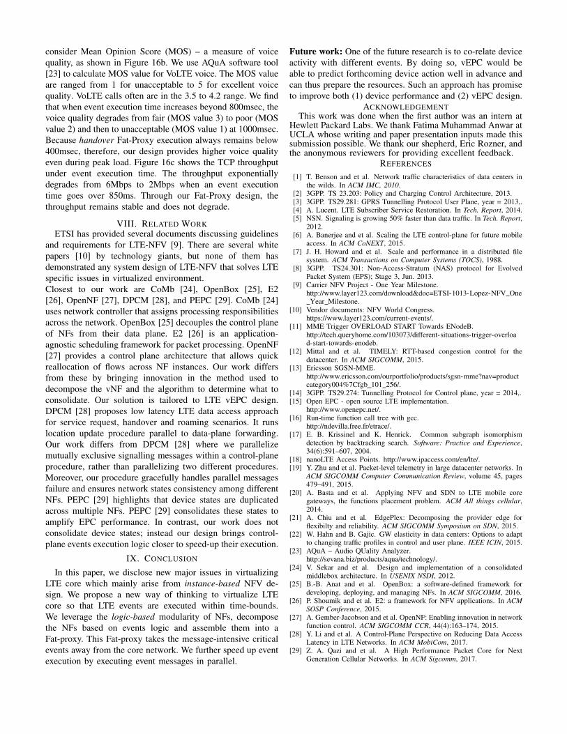
consider Mean Opinion Score (MOS) – a measure of voicequality, as shown in Figure 16b. We use AQuA software tool[23] to calculate MOS value for VoLTE voice. The MOS valueare ranged from 1 for unacceptable to 5 for excellent voicequality. VoLTE calls often are in the 3.5 to 4.2 range. We findthat when event execution time increases beyond 800msec, thevoice quality degrades from fair (MOS value 3) to poor (MOSvalue 2) and then to unacceptable (MOS value 1) at 1000msec.Because handover Fat-Proxy execution always remains below400msec, therefore, our design provides higher voice qualityeven during peak load. Figure 16c shows the TCP throughputunder event execution time. The throughput exponentiallydegrades from 6Mbps to 2Mbps when an event executiontime goes over 850ms. Through our Fat-Proxy design, thethroughput remains stable and does not degrade.
VIII. RELATED WORKETSI has provided several documents discussing guidelines
and requirements for LTE-NFV [9]. There are several whitepapers [10] by technology giants, but none of them hasdemonstrated any system design of LTE-NFV that solves LTEspecific issues in virtualized environment.Closest to our work are CoMb [24], OpenBox [25], E2[26], OpenNF [27], DPCM [28], and PEPC [29]. CoMb [24]uses network controller that assigns processing responsibilitiesacross the network. OpenBox [25] decouples the control planeof NFs from their data plane. E2 [26] is an application-agnostic scheduling framework for packet processing. OpenNF[27] provides a control plane architecture that allows quickreallocation of flows across NF instances. Our work differsfrom these by bringing innovation in the method used todecompose the vNF and the algorithm to determine what toconsolidate. Our solution is tailored to LTE vEPC design.DPCM [28] proposes low latency LTE data access approachfor service request, handover and roaming scenarios. It runslocation update procedure parallel to data-plane forwarding.Our work differs from DPCM [28] where we parallelizemutually exclusive signalling messages within a control-planeprocedure, rather than parallelizing two different procedures.Moreover, our procedure gracefully handles parallel messagesfailure and ensures network states consistency among differentNFs. PEPC [29] highlights that device states are duplicatedacross multiple NFs. PEPC [29] consolidates these states toamplify EPC performance. In contrast, our work does notconsolidate device states; instead our design brings control-plane events execution logic closer to speed-up their execution.
IX. CONCLUSION
In this paper, we disclose new major issues in virtualizingLTE core which mainly arise from instance-based NFV de-sign. We propose a new way of thinking to virtualize LTEcore so that LTE events are executed within time-bounds.We leverage the logic-based modularity of NFs, decomposethe NFs based on events logic and assemble them into aFat-proxy. This Fat-proxy takes the message-intensive criticalevents away from the core network. We further speed up eventexecution by executing event messages in parallel.
Future work: One of the future research is to co-relate deviceactivity with different events. By doing so, vEPC would beable to predict forthcoming device action well in advance andcan thus prepare the resources. Such an approach has promiseto improve both (1) device performance and (2) vEPC design.
ACKNOWLEDGEMENTThis work was done when the first author was an intern at
Hewlett Packard Labs. We thank Fatima Muhammad Anwar atUCLA whose writing and paper presentation inputs made thissubmission possible. We thank our shepherd, Eric Rozner, andthe anonymous reviewers for providing excellent feedback.
REFERENCES
[1] T. Benson and et al. Network traffic characteristics of data centers inthe wilds. In ACM IMC, 2010.
[2] 3GPP. TS 23.203: Policy and Charging Control Architecture, 2013.[3] 3GPP. TS29.281: GPRS Tunnelling Protocol User Plane, year = 2013,.[4] A. Lucent. LTE Subscriber Service Restoration. In Tech. Report, 2014.[5] NSN. Signaling is growing 50% faster than data traffic. In Tech. Report,
2012.[6] A. Banerjee and et al. Scaling the LTE control-plane for future mobile
access. In ACM CoNEXT, 2015.[7] J. H. Howard and et al. Scale and performance in a distributed file
system. ACM Transactions on Computer Systems (TOCS), 1988.[8] 3GPP. TS24.301: Non-Access-Stratum (NAS) protocol for Evolved
Packet System (EPS); Stage 3, Jun. 2013.[9] Carrier NFV Project - One Year Milestone.
http://www.layer123.com/download&doc=ETSI-1013-Lopez-NFV OneYear Milestone.
[10] Vendor documents: NFV World Congress.https://www.layer123.com/current-events/.
[11] MME Trigger OVERLOAD START Towards ENodeB.http://tech.queryhome.com/103073/different-situations-trigger-overload-start-towards-enodeb.
[12] Mittal and et al. TIMELY: RTT-based congestion control for thedatacenter. In ACM SIGCOMM, 2015.
[13] Ericsson SGSN-MME.http://www.ericsson.com/ourportfolio/products/sgsn-mme?nav=productcategory004%7Cfgb 101 256/.
[14] 3GPP. TS29.274: Tunnelling Protocol for Control plane, year = 2014,.[15] Open EPC - open source LTE implementation.
http://www.openepc.net/.[16] Run-time function call tree with gcc.
http://ndevilla.free.fr/etrace/.[17] E. B. Krissinel and K. Henrick. Common subgraph isomorphism
detection by backtracking search. Software: Practice and Experience,34(6):591–607, 2004.
[18] nanoLTE Access Points. http://www.ipaccess.com/en/lte/.[19] Y. Zhu and et al. Packet-level telemetry in large datacenter networks. In
ACM SIGCOMM Computer Communication Review, volume 45, pages479–491, 2015.
[20] A. Basta and et al. Applying NFV and SDN to LTE mobile coregateways, the functions placement problem. ACM All things cellular,2014.
[21] A. Chiu and et al. EdgePlex: Decomposing the provider edge forflexibilty and reliability. ACM SIGCOMM Symposium on SDN, 2015.
[22] W. Hahn and B. Gajic. GW elasticity in data centers: Options to adaptto changing traffic profiles in control and user plane. IEEE ICIN, 2015.
[23] AQuA – Audio QUality Analyzer.http://sevana.biz/products/aqua/technology/.
[24] V. Sekar and et al. Design and implementation of a consolidatedmiddlebox architecture. In USENIX NSDI, 2012.
[25] B.-B. Anat and et al. OpenBox: a software-defined framework fordeveloping, deploying, and managing NFs. In ACM SIGCOMM, 2016.
[26] P. Shoumik and et al. E2: a framework for NFV applications. In ACMSOSP Conference, 2015.
[27] A. Gember-Jacobson and et al. OpenNF: Enabling innovation in networkfunction control. ACM SIGCOMM CCR, 44(4):163–174, 2015.
[28] Y. Li and et al. A Control-Plane Perspective on Reducing Data AccessLatency in LTE Networks. In ACM MobiCom, 2017.
[29] Z. A. Qazi and et al. A High Performance Packet Core for NextGeneration Cellular Networks. In ACM Sigcomm, 2017.


![An Adaptive Mechanism for LTE P-GW Virtualization using ...luciano/publications/cnsm17.pdf · Networking (SDN) [1] and Network Function Virtualization (NFV) [4] can be used to redesign](https://static.fdocuments.us/doc/165x107/6037b8e9fdb0c922526edaa7/an-adaptive-mechanism-for-lte-p-gw-virtualization-using-lucianopublicationscnsm17pdf.jpg)