RETENTION WALL SYSTEM - HCI · The CHANCE® Underpinning/Shoring system provides for underpinning...
22
RETENTION WALL SYSTEM Page 9-1 | Hubbell Power Systems, Inc. | All Rights Reserved | Copyright © 2014
Transcript of RETENTION WALL SYSTEM - HCI · The CHANCE® Underpinning/Shoring system provides for underpinning...

RETENTION WALL SYSTEM
Page 9-1 | Hubbell Power Systems, Inc. | All Rights Reserved | Copyright © 2014

RETE
NTIO
N W
ALL S
YSTE
M
Page 9-2 | Hubbell Power Systems, Inc. | All Rights Reserved | Copyright © 2014
INTRODUCTION ................................................................................... 9-4PRODUCT BENEFITS ............................................................................ 9-4SYSTEM DESCRIPTION ........................................................................ 9-5SOIL SCREW® RETENTION WALL SYSTEM SELECTION GUIDELINES ... 9-5PRELIMINARY DESIGN CONSIDERATIONS ........................................... 9-8PRELIMINARY DESIGN RECOMMENDATIONS ..................................... 9-8GEOTECHNICAL and STRUCTURAL ENGINEERING .............................. 9-9LIMITING LOAD CAPACITIES ................................................................ 9-11GENERAL CONSTRUCTION CONSIDERATIONS of ................................. 9-12UNDERPINNING/SHORING SYSTEMSCONCEPTS and APPLICATIONS of UNDERPINNING/SHORING SYSTEMS 9-13CASE STUDY 1 - HIGH FOUNDATION LINE LOAD with SHALLOW CUT 9-14CASE STUDY 2 - LOW FOUNDATION LINE with DEEP CUT ................. 9-19
SOIL SCREW® RETENTION WALL SYSTEMSECTION 9
CONTENTS

RETENTION WALL SYSTEM
Page 9-3 | Hubbell Power Systems, Inc. | All Rights Reserved | Copyright © 2014
FS ...............................................................................Factor of Safety 9-5AWS ..........................................................American Welding Society 9-7SPT ............................................................ Standard Penetration Test 9-8N ................................................................................SPT Blow Count 9-8LI ................................................................................. Liquidity Index 9-8Kt ................................................................... Empirical Torque Factor 9-11c .................................................................................Cohesion of Soil 9-15j ................................................................ Angle of Internal Friction 9-15q ......................................................................... Failure Plane Angle 9-14RF ................................................................................Resisting Force 9-17DF .................................................................................. Driving Force 9-17SSCF .................................... SOIL SCREW® Anchor Component Force 9-17WWF ................................................................... Welded Wire Fabric 9-18GWT .................................................................... Ground Water Table 9-19Pdes .................................................................... Design Load per Pier 9-15DS ....................................................................................Design Load 9-15T .................................................................................. Indicated Force 9-20
DISCLAIMER
The information in this manual is provided as a guide to assist you with your design and in writing your own specifications.
Installation conditions, including soil and structure conditions, vary widely from location to location and from point to point on a site.
Independent engineering analysis and consulting state and local building codes and authorities should be conducted prior to any installation to ascertain and verify compliance to relevant rules, regulations and requirements.
Hubbell Power Systems, Inc., shall not be responsible for, or liable to you and/or your customers for the adoption, revision, implementation, use or misuse of this information. Hubbell, Inc., takes great pride and has every confidence in its network of installing contractors and dealers.
Hubbell Power Systems, Inc., does NOT warrant the work of its dealers/installing contractors in the installation of CHANCE® Civil Construction foundation support products.
SYMBOLS USED IN THIS SECTION
RETE
NTIO
N W
ALL S
YSTE
M
Page 9-4 | Hubbell Power Systems, Inc. | All Rights Reserved | Copyright © 2014
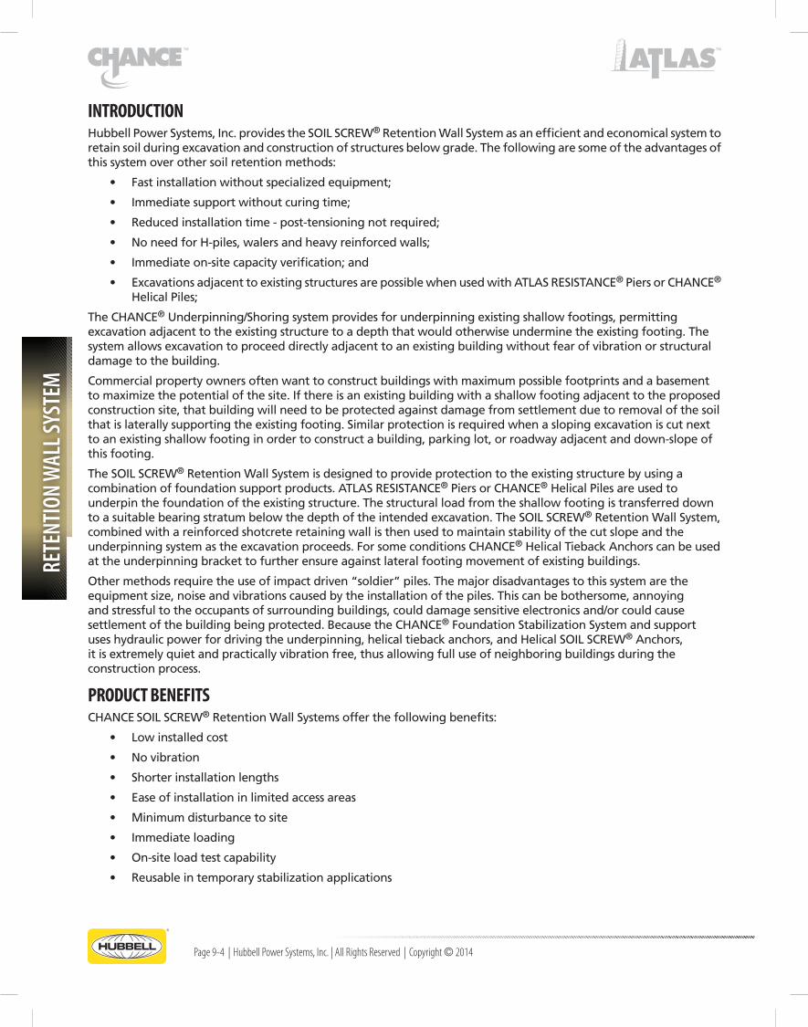
INTRODUCTION Hubbell Power Systems, Inc. provides the SOIL SCREW® Retention Wall System as an efficient and economical system to retain soil during excavation and construction of structures below grade. The following are some of the advantages of this system over other soil retention methods:
• Fastinstallationwithoutspecializedequipment;
• Immediatesupportwithoutcuringtime;
• Reducedinstallationtime-post-tensioningnotrequired;
• NoneedforH-piles,walersandheavyreinforcedwalls;
• Immediateon-sitecapacityverification;and
• ExcavationsadjacenttoexistingstructuresarepossiblewhenusedwithATLASRESISTANCE®PiersorCHANCE® HelicalPiles;
TheCHANCE® Underpinning/Shoring system provides for underpinning existing shallow footings, permitting excavationadjacenttotheexistingstructuretoadepththatwouldotherwiseunderminetheexistingfooting.Thesystemallowsexcavationtoproceeddirectlyadjacenttoanexistingbuildingwithoutfearofvibrationorstructuraldamage to the building.
Commercial property owners often want to construct buildings with maximum possible footprints and a basement tomaximizethepotentialofthesite.Ifthereisanexistingbuildingwithashallowfootingadjacenttotheproposedconstruction site, that building will need to be protected against damage from settlement due to removal of the soil thatislaterallysupportingtheexistingfooting.Similarprotectionisrequiredwhenaslopingexcavationiscutnexttoanexistingshallowfootinginordertoconstructabuilding,parkinglot,orroadwayadjacentanddown-slopeofthis footing.
The SOIL SCREW® Retention Wall System is designed to provide protection to the existing structure by using a combinationoffoundationsupportproducts.ATLASRESISTANCE®PiersorCHANCE® Helical Piles are used to underpin the foundation of the existing structure. The structural load from the shallow footing is transferred down to a suitable bearing stratum below the depth of the intended excavation. The SOIL SCREW® Retention Wall System, combined with a reinforced shotcrete retaining wall is then used to maintain stability of the cut slope and the underpinningsystemastheexcavationproceeds.ForsomeconditionsCHANCE®HelicalTiebackAnchorscanbeusedat the underpinning bracket to further ensure against lateral footing movement of existing buildings.
Othermethodsrequiretheuseofimpactdriven“soldier”piles.Themajordisadvantagestothissystemaretheequipmentsize,noiseandvibrationscausedbytheinstallationofthepiles.Thiscanbebothersome,annoyingand stressful to the occupants of surrounding buildings, could damage sensitive electronics and/or could cause settlementofthebuildingbeingprotected.BecausetheCHANCE®FoundationStabilizationSystemandsupportuses hydraulic power for driving the underpinning, helical tieback anchors, and Helical SOIL SCREW®Anchors,itisextremelyquietandpracticallyvibrationfree,thusallowingfulluseofneighboringbuildingsduringtheconstruction process.
PRODUCT BENEFITSCHANCE SOIL SCREW® Retention Wall Systems offer the following benefits:
• Lowinstalledcost
• Novibration
• Shorterinstallationlengths
• Easeofinstallationinlimitedaccessareas
• Minimumdisturbancetosite
• Immediateloading
• On-siteloadtestcapability
• Reusableintemporarystabilizationapplications
RETENTION WALL SYSTEM
Page 9-5 | Hubbell Power Systems, Inc. | All Rights Reserved | Copyright © 2014
SYSTEM DESCRIPTIONTheCHANCESOILSCREW® Retention Wall System creates an internally reinforced soil mass when closely spaced in a regular geometric pattern and protected by a reinforced facing of shotcrete. It differs from helical tieback anchors even though the appearance of the products is similar.
Atiebackrestrainedwallisgenerallyconstructedbyinstallingastructuralwallfacingsystemthatisanchoredtotheearth by means of high strength helical anchors that are installed to a stratum of soil of sufficient strength to resist theforcesplaceduponthewallbytheretainedearth.Thehelicaltiebackanchorexperiencesatensionloadequalto the retained earth forces. The structural retaining wall must be designed with sufficient strength to be able to support the soil load between tiebacks without excessive deformation.
CHANCE® Helical SOIL SCREW®Anchorsaredesignedandinstalleddifferentlythanhelicaltiebackanchors.Theyaregenerallyseatedatashallowerdepththanhelicaltiebackanchorswheninstalledtoretainsimilarsoilmasses.Mostimportantly, the Helical SOIL SCREW®Anchorsarenottensionedafterinstallation;theyarepassiveelements.Whenthe SOIL SCREW® Retention Wall System is installed it holds the soil as a single mass of sufficient internal stability to provideasuitableFactorofSafety(FS)againstfailure.TheloadontheHelicalSOILSCREW®Anchorsiscreatedacrossthe movement plane as the soil mass moves slightly downward due to gravity.
Manyprojectsrequirethatexcavationsbeextremelyclosetoexistingstructures.BycombiningATLASRESISTANCE® ModifiedPiers,orCHANCE®HelicalPiles,CHANCE®HelicalTiebackAnchors,andtheCHANCESOILSCREW® Retention Wall System together, the designer is able to safely support an existing structure and the underlying soil massduringadjacentexcavations.ATLASRESISTANCE®PiersorCHANCE® Helical Piles support the structural load of the perimeter of the building, thus dramatically reducing the surcharge on the soil mass that must be retained. CHANCE®HelicalTiebackAnchorsareusedforlateralsupportofthebuilding’sfootinginprojectswheredeep,adjacentexcavationsarerequiredand/orforbuildingswithperimeterweightsexceeding4,000poundsperlinearfoot. With the surcharge loads properly transferred away from the soil mass under the building, the design for soil retentionusingCHANCE® Helical SOIL SCREW®AnchorsisgreatlysimplifiedandrequiresfewerHelicalSOILSCREW® Anchors.Inmanyinstances,thismethodistheonlyeconomicalwaytoaccomplishthistask.Thismethodofstructure/soil mass support prevents structure distress that may manifest itself during potential settlement as the soil mass loadstheCHANCESOILSCREW® Retention Wall System.
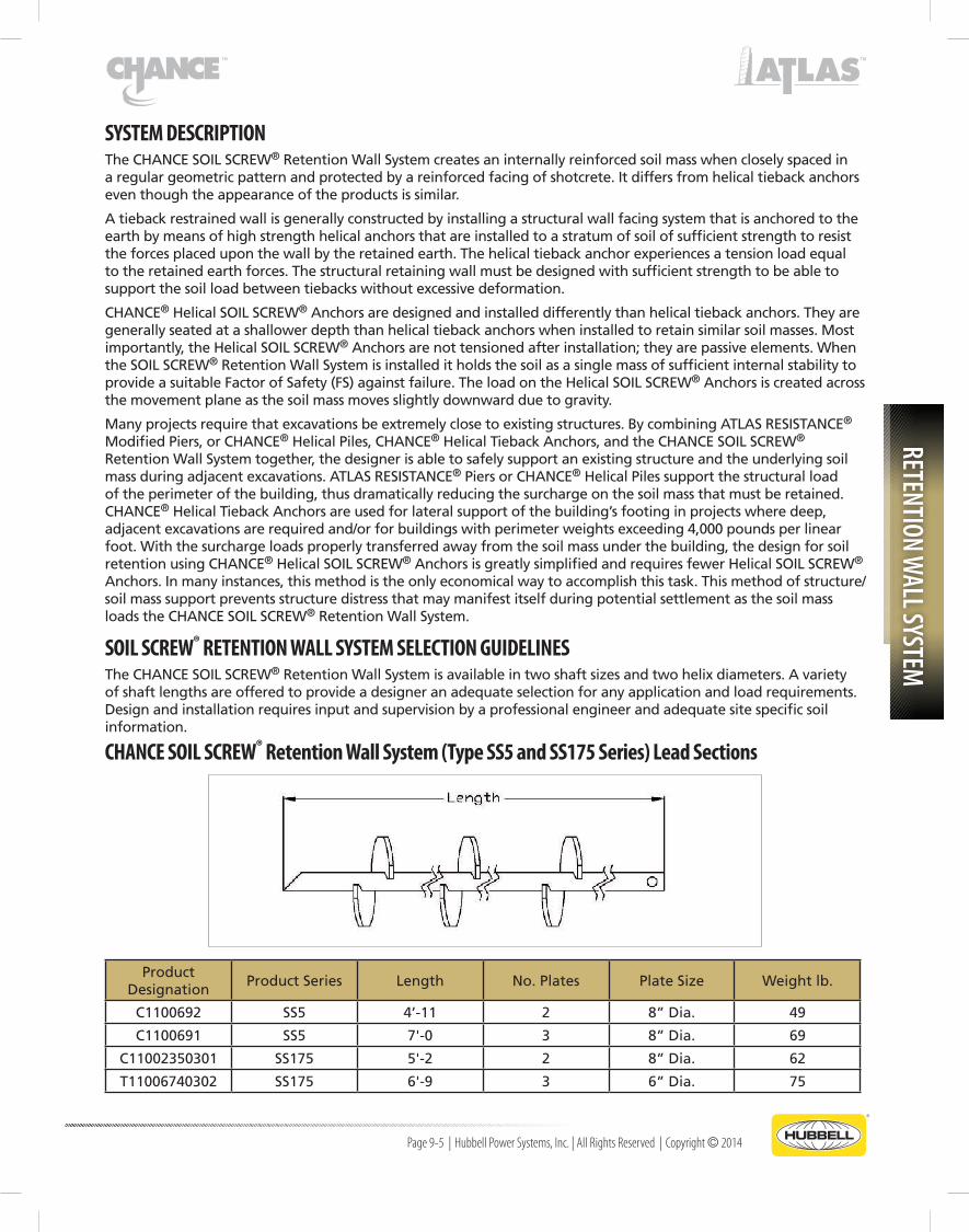
SOIL SCREW® RETENTION WALL SYSTEM SELECTION GUIDELINESTheCHANCESOILSCREW®RetentionWallSystemisavailableintwoshaftsizesandtwohelixdiameters.Avarietyofshaftlengthsareofferedtoprovideadesigneranadequateselectionforanyapplicationandloadrequirements.Designandinstallationrequiresinputandsupervisionbyaprofessionalengineerandadequatesitespecificsoilinformation.
CHANCE SOIL SCREW® Retention Wall System (Type SS5 and SS175 Series) Lead Sections
Product Designation
Product Series Length No.Plates PlateSize Weight lb.
C1100692 SS5 4’-11 2 8”Dia. 49
C1100691 SS5 7'-0 3 8”Dia. 69
C11002350301 SS175 5'-2 2 8”Dia. 62
T11006740302 SS175 6'-9 3 6”Dia. 75

RETE
NTIO
N W
ALL S
YSTE
M
Page 9-6 | Hubbell Power Systems, Inc. | All Rights Reserved | Copyright © 2014
CHANCE SOIL SCREW® Retention Wall System (Type SS5 and SS175 Series) Extension Sections
Product Designation
Product Series Length No.Plates PlateSize Weight lb.
C1100690 SS5 4'-9 2 8”Dia. 42
C1100689 SS5 6'-9 3 8”Dia. 50
C11004500301 SS175 6'-11 2 6”Dia. 70
C11004500302 SS175 6'-10 3 8”Dia. 75
CONFIGURATIONS - SQUARE SHAFT LEAD SECTIONS
TYPE SS5 and SS175 SERIES

RETENTION WALL SYSTEM
Page 9-7 | Hubbell Power Systems, Inc. | All Rights Reserved | Copyright © 2014
CHANCE SOIL SCREW® Retention Wall System (Type SS5 and SS175 Series) Lead SectionsCONFIGURATIONTABLE(LeadsandExtensions)
BarSize PlateSize Length DimA Dim B Dim C No.Plates
1-1/2"SquareSoilScrew® Lead Section
8"Dia.4'-11 6" 29" 24" 2
7'-0 6" 29" 20" 3
1-1/2"SquareSoilScrew® Extension
8"Dia.4'-9 5" 29" 23" 2
6'-9 6" 29" 17" 3
1-3/4"SquareSoilScrew® Lead Section
6"Dia. 5'-2 8" 30" 24" 2
8"Dia. 6'-9 6" 30" 15" 3
1-3/4"SquareSoilScrew® Extension
6"Dia. 6'-11 6" 30" 17" 3
8”Dia. 6'-10 9" 29" 15" 3
NOTES – SOIL SCREW® ANCHOR PRODUCTS (Type SS5 and SS175 Series):
• Refertotheschematicdrawingsatthebottomofpage9-6andbelowforDimensionsA,BandC.
• Allextensionsincludeintegrallyforgedcouplings,machineboltsandhexnuts
• AllhelicalplatesareweldedtotheshaftinconformancetotheAmericanWeldingSociety(AWS)StructuralWeldingCodeAWSD1.1”andapplicablerevisions.
• AvailableFinish:HotDipGalvanized(HDG)
CONFIGURATIONS - SQUARE SHAFT EXTENSION SECTIONS
TYPE SS5 and SS175 SERIES

RETE
NTIO
N W
ALL S
YSTE
M
Page 9-8 | Hubbell Power Systems, Inc. | All Rights Reserved | Copyright © 2014
PRELIMINARY DESIGN CONSIDERATIONSThefollowingrequirementsmustbeconsidered:
1. Anevaluationof:(a)thefoundationsoilstrata(belowthereinforcedsoilmass),(b)thesoilstratumintowhichthehelixplateswillbelocated,and(c)thesoilbehindthereinforcedsoilmasstoberetainedbytheSOILSCREW® Retention Wall System.
2. AselectionoftheappropriateHelicalSOILSCREW®Anchorincludingshaftsize,helixplatediameterandlengthofembedment.
3. AdeterminationoftheultimatetensioncapacityoftheHelicalSOILSCREW®AnchorswithasuitableFactorofSafety.
The following preliminary design guide for Helical SOIL SCREW®Anchorsisintendedtoprovideabasicunderstandingof SOIL SCREW® Retaining Wall theory.
SOIL SCREW® Anchor wall design requires professional geotechnical and engineering input. Specific information involving the structures, soil characteristics and foundation conditions must be used for the final design.
PRELIMINARY DESIGN RECOMMENDATIONS• ThetopoftheHelicalSOILSCREW®Anchorwalltypicallymovesintherangeof0.1%to0.3%ofthewall
height.Verticalandlateralmovementsareexpectedtobeapproximately1/4”foraten-footcutand1/2”fora20-footcut.Thislateralmovementisofconcernwhenthereisastructurelocatedatthetopoftheproposedcut.ItisthereforerequiredthateitherATLASRESISTANCE®PiersorCHANCE® Helical Piles underpin theexistingstructure.ItisrecommendedtouseCHANCE®HelicalTiebackAnchorsateachunderpinningplacementlocationwheneverthecutexceeds12feetand/ortheexistingstructurallineloadisgreaterthan4,000lb/ft.
• Surchargeloadsduetoslabs,columnfootings,overburdensoils,vehiculartraffic,orotherstructuresbehindthewall must be considered when calculating the soil loads to be retained by the Helical SOIL SCREW®Anchors.
• TheCHANCE® SOIL SCREW®RetentionWallSystemisbestsuitedtocementedormedium-densetodensesandandtolowplasticityclaysoilswithStandardPenetrationTest(SPT)Nvalues≥ 8. Use caution in highly plastic clays and silts.
• TheCHANCE® SOIL SCREW®RetentionWallSystemispoorlysuitedforjointedweatheredrockmaterialthatdipsintotheexcavation,loosesandwithSPTNvalues≤7andinthosecohesivesoilswithSPTNvaluesof≤ 6(clayswithcohesion<850psforanallowablebearingstress<2,000psf)anywhereinthedepthprofileofsoil that is to be excavated.
• Cleantorelativelycleancohesionlesssoilswithpoorstand-uptimetypicallyrequirea1”(±)flashshotcretecoating to be placed simultaneously with the excavation. The maximum recommended incremental face cut heightisfourfeetorless.UseCHANCE®HelicalTiebackAnchorswhenunderpinning/shoringnexttoanexisting structure.
• Useoftheunderpinning/shoringsystemispermissibleforexcavationsofupto20feetandunderextremelyfavorableconditionsshallnotexceed25feet.
• Theunderpinning/shoringsystemisatemporarysupportsystem.Creepisgenerallynotaproblem,however,thesystemisnotrecommendedwhentheLiquidityIndex(LI)is>0.2.
• SOILSCREW®Anchorsmusthavehelixplatesofthesamediametercontinuouslyalongtheinstalledlength.
• SOILSCREW®Anchorsmustbeinstalledataminimumdownwardangleof5°fromhorizontalandtypicallydonotexceed15°downwardangle.
• Engineeringdesignshallincludeverificationofseverallevelsofdesignanalysis:
Internal stability: The soil mass acts as a coherent mass
External stability: The ability to resist lateral sliding
Globalstability: Theabilitytoresistmassiverotationalfailureoutsidethe“internallystabilizedsoil”mass

RETENTION WALL SYSTEM
Page 9-9 | Hubbell Power Systems, Inc. | All Rights Reserved | Copyright © 2014
IMPORTANT NOTICE
A Registered Professional Engineer shall design the ChAnCE SOIL SCREW® Retention Wall System. The installation shall be performed by trained and certified installing contractors/dealers.
GEOTECHNICAL and STRUCTURAL ENGINEERINGFor an introduction and guidance on how to design retention walls us-ing the ChAnCE SOIL SCREW® Retention Wall System, refer to the SOIL SCREW® Retention Wall System Design Manual. For a copy of this man-ual, please contact your area ChAnCE® Distributor or visit the hubbell Power Systems, Inc. website at www.abchance.com.
Design Example 10 in Section 8 provides a detailed wall design using the ChAnCE SOIL SCREW® Retention Wall System.
CHANCEHelicalSOILSCREW®Anchorslooksimilartohelicaltiebackanchors,buttheyaredifferentandtheyactdifferentlytostabilizeaslope.To understand how Helical SOIL SCREW®Anchorsactandthedifferencesbetween the two products, we must examine a cut slope that is unable to standforanextendedtimeonitsown(seeFigure9-1).
Asimplemethodtoimprovestabilityoftheslopewouldbetostackrailroad ties against the cut face so that the soil would have to push the tiesoverintheprocessoffailing(seeFigure9-2).Ifthisprovesinsufficient,driving“soldier”pilesinfrontoftherailroadties(nowtermed“lagging”)enhancesthestability.Nowthesoilmustpushthelaggingandthesoldierpilesoverbeforefailurecanoccur(seeFigure9-3).
Ifthisisstillinsufficienttostabilizethesoil,abeamcanbeinstalledalongthewallconnectingthesoldierpiles.Thisbeamiscalleda“waler”anditisanchored by helical tieback anchors to a stable portion of the soil mass be-hindthefailureplane(seeFigure9-4).Nowastheslopeattemptstofail,the sliding soil pushes against the lagging, the lagging pushes against the soldier piles, the soldier piles push against the waler, and the waler pulls on the tiebacks. If the helical tieback anchors provide enough resistance, thewholesystemisstable.Thedesignofthewallsystem(thelagging,soldierpilesandthewaler)bringsthedistributedsoilforceagainstthelagging toward, and concentrates the load at, the helical tieback anchors. Afterthetiebacksareinstalled,theyareusuallypost-tensioned.When
helical tiebacks are used for this type of application, they are typically concentrated in a few tiers, and are designed so that all tension resistance is attained within the stable soil mass behind the potential movement plane.
Helical SOIL SCREW®Anchorsdifferfromhelicaltiebackanchorsbecausetheyaredesignedtoattainpulloutresis-tancewithintheslidingsoilmassaswellasthestablemassbehindthemovementplane.ForHelicalSOILSCREW® Anchorstobeeffective,theymusthavehelicesalongthewholelengthoftheshaft.Whentheunstablesoilmassbeginstoslide,itmovesagainstthehelicesburiedwithinthisunstablemass(seeFigure9-5).Theresistancegener-ated on the helices within the unstable mass secures the soil directly and reduces the resulting soil pressure against the wall. The net effect is that Helical SOIL SCREW®Anchorsreducethestructuralrequirementsforthewallsystem.In most cases the Helical SOIL SCREW®Anchorsareconnecteddirectlytothewallwithouttheuseofsoldierpilesorwalers.Theretainingwallisthereforethinnerthanawallrequiredwhenusingtiebackanchors.
Helical SOIL SCREW®Anchorsaremoreevenlydistributedonthewallandthereforecarrylighterloadsthanhelicaltieback anchors. Helical SOIL SCREW®Anchorsshouldnotbepost-tensionedaspost-tensioningputsbearingstressesonthewrongsideofthehelicesthatareembeddedintheunstablesoilmass.Someengineersrequirethatasmallload(1000poundsorless)beappliedtonewlyinstalledHelicalSOILSCREW®Anchorstoremoveanyslackintheconnections.
Typical Failure Mode of an Unstable ExcavationFigure 9-1
Cut Slope with Timber WallFigure 9-2

RETE
NTIO
N W
ALL S
YSTE
M
Page 9-10 | Hubbell Power Systems, Inc. | All Rights Reserved | Copyright © 2014
Because Helical SOIL SCREW®Anchorsarenotpost-tensioned,theunstablesoil mass has to slump slightly before the SOIL SCREW® System can develop resistance. SOIL SCREW®RetainingWallsdeflectbothverticallydownwardand laterally outward during this slumping process. The magnitudes of bothdeflectionstypicallyvaryfrom0.1%to0.3%ofthewallheight(seeFigure9-6).Forexample,thetopofa12-foothighwallwilltypicallydeflectfrom1/8”to3/8”downwardandoutward.Because3/8”settlementap-proaches the level that can cause damage in some structures, the Hubbell Power Systems, Inc. Underpinning/Shoring System includes helical tieback anchors at the underpinning bracket whenever excavation depths exceed 12feetorstructuralfootingloadsexceed4,000lb/ft.Post-tensioningthesetiebackanchorspriortoexcavationallowsthedeflectionsatthefootingtobe controlled to an acceptable level.
Because of the potential severity of a structural failure involving one of these systems, Hubbell Power Systems, Inc. recommends that a staff applica-
tionengineer,oranengineerfromanauthorizedCHANCE® Distributor perform a preliminary design and make a final wall design review. The preliminary design will give recommenda-tions for the Helical SOIL SCREW®Anchorsand,iftheprojectrequires,specificunderpinningpiers/pilesand/orhelicaltiebackanchorstobeusedonthespecificproject.Detailsfortheplace-mentoftheproducts,therequiredembedmentdepthsandminimuminstallationresistancesandtorqueswillberecom-mended. These preliminary recommendations, estimates of installation depths and wall thickness will aid in preparing cost estimates. Both the installing contractor/dealer and the Engineer of Record shall review these recommendations. The CHANCE® Distributor or Hubbell Power Systems, Inc. Engineer willworkwiththeEngineerofRecordasrequiredtoresolveany issues regarding the preliminary design. The Engineer of Record must accept and approve the final design before con-struction can begin.
Shotcrete
Shotcrete is portland cement concrete or mortar propelled at highvelocity(typicallybyairpressure)ontoasurface.Withwet process shotcrete, the dry materials are mixed with water andpumpedtoanozzle,whereairisaddedtoprojectthematerial onto the surface. Dry process shotcrete, also known as “gunite”,deliversthedrymaterialtothenozzlebyairpressurewhere water is added at the point of discharge. The water and dry materials mix during deposition. Each process has its own advantages and disadvantages, but either, or both, may be usedtoconstructthewallfacingfortheCHANCESOILSCREW® Retention Wall System.
The wet process allows for high deposition rates up to three timestherateattainablewithgunitewithlessrebound(5%vs.
15%forgunite).Inaddition,thenozzlemanneednotbeashighlyskilledforthisprocess.Themajordisadvantagestotheshotcretewetprocessaretheextensivecleanuprequiredandthedifficultyschedulingready-mixdeliveries.Thegunite(dry)processhastheadvantageofeasycleanupandtheabilitytomixmaterialsonsite.Gunitehasmoredisadvantagesthanshotcrete.Gunitehasarelativelylowdepositionrate(slowerapplication),hasmorereboundandrequireshighlyskilledoperators.
Cut Slope with Solder Pile and LaggingFigure 9-3
Cut Slope with Tieback WallFigure 9-4
Cut Slope Stabilized with Helical SOIL SCREW® Anchors
Figure 9-5
RETENTION WALL SYSTEM
Page 9-11 | Hubbell Power Systems, Inc. | All Rights Reserved | Copyright © 2014
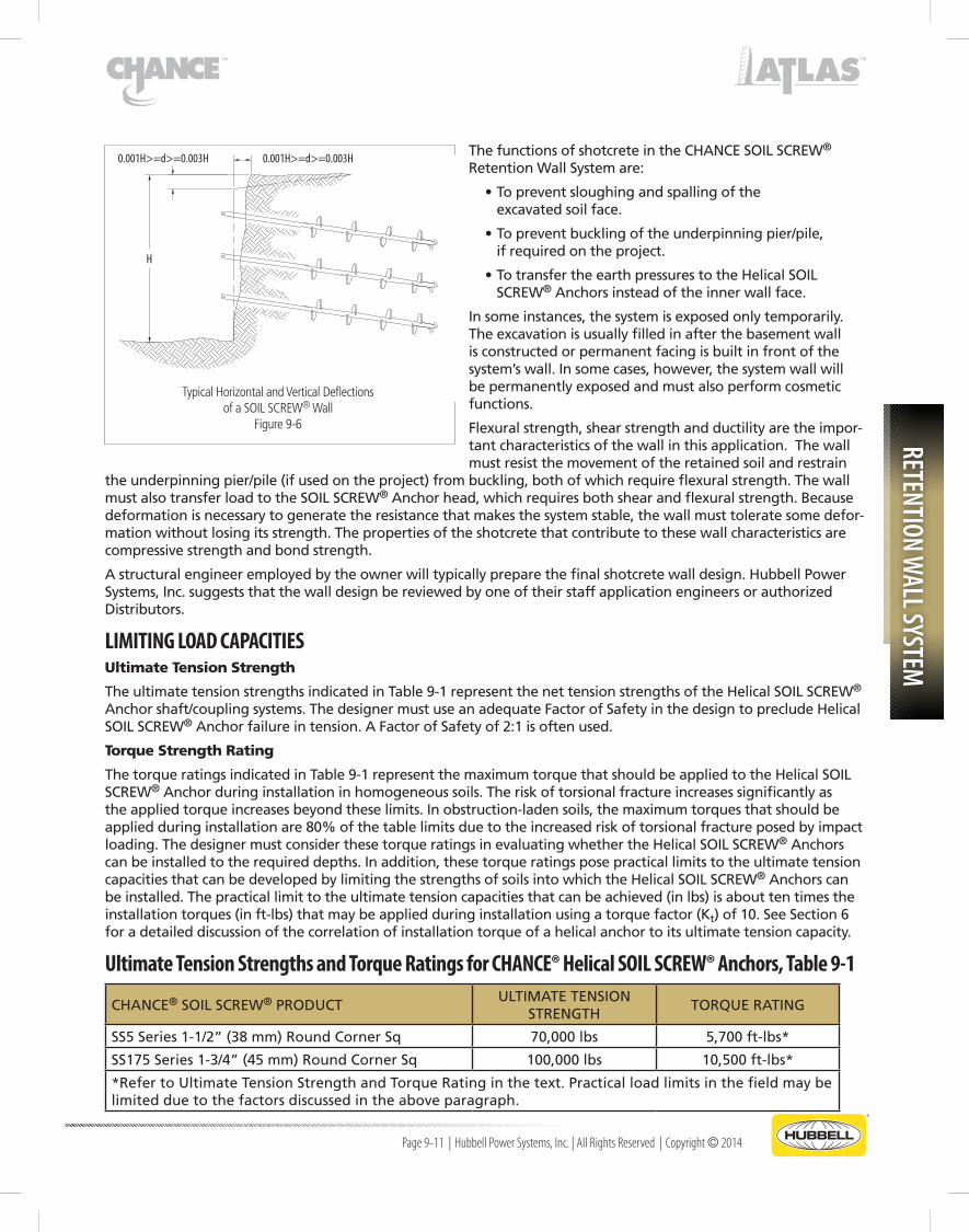
ThefunctionsofshotcreteintheCHANCESOILSCREW® Retention Wall System are:
•Topreventsloughingandspallingofthe excavated soil face.
•Topreventbucklingoftheunderpinningpier/pile, ifrequiredontheproject.
•TotransfertheearthpressurestotheHelicalSOIL SCREW®Anchorsinsteadoftheinnerwallface.
In some instances, the system is exposed only temporarily. The excavation is usually filled in after the basement wall is constructed or permanent facing is built in front of the system’swall.Insomecases,however,thesystemwallwillbe permanently exposed and must also perform cosmetic functions.
Flexuralstrength,shearstrengthandductilityaretheimpor-tant characteristics of the wall in this application. The wall must resist the movement of the retained soil and restrain
theunderpinningpier/pile(ifusedontheproject)frombuckling,bothofwhichrequireflexuralstrength.Thewallmust also transfer load to the SOIL SCREW®Anchorhead,whichrequiresbothshearandflexuralstrength.Becausedeformation is necessary to generate the resistance that makes the system stable, the wall must tolerate some defor-mation without losing its strength. The properties of the shotcrete that contribute to these wall characteristics are compressive strength and bond strength.
Astructuralengineeremployedbytheownerwilltypicallypreparethefinalshotcretewalldesign.HubbellPowerSystems,Inc.suggeststhatthewalldesignbereviewedbyoneoftheirstaffapplicationengineersorauthorizedDistributors.
LIMITING LOAD CAPACITIESUltimate Tension Strength
TheultimatetensionstrengthsindicatedinTable9-1representthenettensionstrengthsoftheHelicalSOILSCREW® Anchorshaft/couplingsystems.ThedesignermustuseanadequateFactorofSafetyinthedesigntoprecludeHelicalSOIL SCREW®Anchorfailureintension.AFactorofSafetyof2:1isoftenused.
Torque Strength Rating
ThetorqueratingsindicatedinTable9-1representthemaximumtorquethatshouldbeappliedtotheHelicalSOILSCREW®Anchorduringinstallationinhomogeneoussoils.Theriskoftorsionalfractureincreasessignificantlyastheappliedtorqueincreasesbeyondtheselimits.Inobstruction-ladensoils,themaximumtorquesthatshouldbeappliedduringinstallationare80%ofthetablelimitsduetotheincreasedriskoftorsionalfractureposedbyimpactloading.ThedesignermustconsiderthesetorqueratingsinevaluatingwhethertheHelicalSOILSCREW®Anchorscanbeinstalledtotherequireddepths.Inaddition,thesetorqueratingsposepracticallimitstotheultimatetensioncapacities that can be developed by limiting the strengths of soils into which the Helical SOIL SCREW®Anchorscanbeinstalled.Thepracticallimittotheultimatetensioncapacitiesthatcanbeachieved(inlbs)isabouttentimestheinstallationtorques(inft-lbs)thatmaybeappliedduringinstallationusingatorquefactor(Kt)of10.SeeSection6foradetaileddiscussionofthecorrelationofinstallationtorqueofahelicalanchortoitsultimatetensioncapacity.
Ultimate Tension Strengths and Torque Ratings for CHANCE® Helical SOIL SCREW® Anchors, Table 9-1
CHANCE® SOIL SCREW® PRODUCTULTIMATETENSION
STRENGTHTORQUERATING
SS5Series1-1/2”(38mm)RoundCornerSq 70,000lbs 5,700ft-lbs*
SS175Series1-3/4”(45mm)RoundCornerSq 100,000lbs 10,500ft-lbs*
*RefertoUltimateTensionStrengthandTorqueRatinginthetext.Practicalloadlimitsinthefieldmaybelimited due to the factors discussed in the above paragraph.
Typical Horizontal and Vertical Deflectionsof a SOIL SCREW® Wall
Figure 9-6
0.001H>=d>=0.003H0.001H>=d>=0.003H
H

RETE
NTIO
N W
ALL S
YSTE
M
Page 9-12 | Hubbell Power Systems, Inc. | All Rights Reserved | Copyright © 2014
GENERAL CONSTRUCTION CONSIDERATIONS of UNDERPINNING/SHORING SYSTEMSTheCHANCESOILSCREW® Retention Wall System for underpinning/shoring next to an existing structure is a specializedconstructionprocessandmustbeinstalledbyCertifiedCHANCE® Installer. Listed below are some general items regarding the construction procedures:
WARnInG! DURInG ThE COURSE OF COnSTRUCTIOn, ThE FOOTInG AnD FACE OF ThE ShORInG ShOULD BE COnTInUOUSLY MOnITORED FOR AnY MOVEMEnTS. IF MOVEMEnTS ARE nOTED, ThE COn-STRUCTIOn PROCESS ShOULD BE STOPPED, TEMPORARY BRACInG InSTALLED AnD ThE EnGInEER AnD/OR GEOTEChnICAL EnGInEER ShOULD BE IMMEDIATELY nOTIFIED FOR FURThER DIRECTIOn.
1. AsisthecaseinconventionalunderpinningofbuildingsusingATLASRESISTANCE®ModifiedPiersorCHANCE® Helical Piles, the footing must be properly prepared so that the pier/pile bracket can be positioned under the footing with a minimum of eccentricity with the wall load. This process may involve chipping the concrete to provide a proper bearing surface and creating a notch in the spread footing to reduce pier/pile eccentricity.
2. ForthoseprojectsrequiringunderpinningandCHANCE®HelicalTiebackAnchorsatthepier/pilebracket,thetiebackmustbeinstalledtotherequiredlengthandtorquepriortoinstallingtheunderpinningsystem.
3. IfATLASRESISTANCE®ModifiedPiersareusedastheunderpinningsystem,theprocessrequirestheuseofpiersleevingtopreventbucklingatthejointsofthepierpipe.Everysleevejointmustbeatleast18”awayfromapierpipejoint.Insomecasesgroutingofthepierpipealongwiththeinsertionofasteelreinforcementbarmaybespecified.
4. Thepiersleevingmustbeinstalledtoaminimumof2feetbelowthedeepestexcavation(cut).
5. IfusingATLASRESISTANCE®ModifiedPiers,thepiersshallbedriventotherequireddepthandloadtestedto150%ofthedesignload.Theneachpiershallbepreloadedtoatleast95%ofthedesignloadandlockedoff.IfusingCHANCE®HelicalPilesastheunderpinningsystem,thehelicalpilesshallbeinstalledtotherequiredminimumdepthsandminimumaverageinstallationtorques.
6. WhentheATLASRESISTANCE®PierorCHANCE® Helical Pile underpinning system installation is complete, the helicaltiebackanchorshallbeattachedtothepier/pilebracketandpreloaded.Normallythetiebackispreloadedto the design load.
7. Upon completion of all of the underpinning and tieback operations, the wall face excavation can commence. Ifthesoilsaregenerallycohesionless(sands,etc.)orthereisanydangerofthesoilfacesloughingoff,a1”thickflashcoatofshotcreteshallbeimmediatelyplacedagainstthefaceofthecutastheexcavationproceeds.If the cut soil is capable of standing by itself, then the first layer of shotcrete can be applied after the initial cutiscomplete.Thesameprocedureshallbefollowedforsubsequentincrementalexcavations.Undernocircumstances should a cut of any height be left open at the face for more than two hours.
8. Thedepthofcutonthefirstexcavation,aswellasonsubsequentincrementalexcavationsshallbeatleastonefoot deeper than the depth of the row of Helical SOIL SCREW®Anchors.SeeFigure9-13,whichshowsa6-footcutand5-footdeeprowofHelicalSOILSCREW®Anchors.
9. Whenthefirstexcavationiscomplete(withorwithoutshotcreteflashcoating),thefirstrowofCHANCE® Helical SOIL SCREW®Anchorsisinstalledtotherequirementsindicatedinthedesignspecifications(lengthofinstallation,minimumtorque,installationangle,etc.).AHelicalSOILSCREW®Anchorshallbepositionedimmediatelyadjacenttoeachunderpinningpier/pile.Shotcreteisplacedontothecutfaceto1/2ofthetotalspecified shotcrete thickness.
10.Theweldedwiremeshreinforcementissetagainstthefaceofthewetshotcretealongthecutfaceofthewallwithexcess reinforcement turned outward at the bottom of the cut to allow for overlap of reinforcement on successive stages.
11. Welded rebar assemblies with bearing plates are positioned over each Helical SOIL SCREW®Anchorandsecuredagainsttheweldedwiremeshreinforcementand(still)wetshotcreteface.
12.Theremainingshotcreteisinstalledtoprovidethetotalthicknessspecified.
13.Steps7through12abovearerepeatedaftereachincrementalexcavation.StabilizationcontinuesuntilalloftheHelical SOIL SCREW®Anchorsareinstalledandthereinforcedshotcretewalliscompletedtothedesigndepth.

RETENTION WALL SYSTEM
Page 9-13 | Hubbell Power Systems, Inc. | All Rights Reserved | Copyright © 2014
CONCEPTS and APPLICATIONS of UNDERPINNING/SHORING SYSTEMSBACKGROUND
Theconstructionofadditionstoofficeandcommercialbuildingsornewconstructionadjacenttoexistingbuildingsrequiresearthexcavationmuchdeeperthanthefootingelevationoftheimmediatelyadjacentbuilding(s).Theuseofsheetpileand/orH-pileswithwoodlaggingtopreventadjacentfootingsubsidencerequirestheuseofdynamicpiledrivingequipmentwiththeattendantvibrationsandnoiselevels.Therearedecideddisadvantagestothesetra-ditionalapproachessincethevibrationsmaycausemovementoftheexistingbuildingfoundationandsubsequentstructuraldamage.Additionally,thevibrationlevelscanoftenleadtoashutdownofbusinessoperationsifconduct-ed during normal working hours.
Hubbell Power Systems, Inc. offers an underpinning/shoring system that not only avoids the vibrations and noise level issues, but also permits the shoring and excavation to proceed at a more rapid pace. In many cases this results in an overall cost savings to the prime contractor and owner. The examples covered below are intended to illustrate some of the design concepts and applications of this system.
Inconductingpreliminarydesignsforprojectsusingtheunderpinning/shoringsystemandinthedevelopmentofthecasestudiesthatfollow,HubbellPowerSystems,Inc.usescertainguidelines.Theseguidelinesarebrieflysummarizedbelow:
1. Hubbell Power Systems, Inc. does not currently recommend using the underpinning/shoring system for excavations exceeding25feet.
2. AlthoughATLASRESISTANCE®PiersorCHANCE®HelicalFoundationPilescanbeusedfortheunderpinningstage;itispreferredtousetheATLASRESISTANCE®Pierif“hardstratum”iswithinareasonabledepthattheproposedconstruction site.
3. TheATLASRESISTANCE® Piers used for underpinning the existing building foundation must be sleeved with the jointsofthesleevesoffsetfromthejointsoftheunderpinningpierpipe.
4. Itisrecommendedincaseswherethelineloadequalsorexceeds4,000poundsperlinealfootand/orthedepthofcutexceeds12feettouseaCHANCE®HelicalTiebackintegratedatthepierbracketlevel.ThisrequirementusesthepierandtiebackcombinationasillustratedinFigure9-11.Thishelicalproductisusedasatiebackan-chor and not a SOIL SCREW®Anchor.
5. Helical SOIL SCREW®Anchorsmustbeinstalledataminimumdownwardangleof5°andgenerallynottoex-ceed15°.
6. AllHelicalSOILSCREW®Anchorshavethesamesizehelixplatescontinuouslyalongtheinstalledlengthoftheshaft.
7. Thebottomcantileverofshotcretewallshouldbelimitedto2/3ofthetypicalspacingfortheHelicalSOILSCREW®Anchorrow,butshouldnotexceed3feet.
8. Ifthefoundationsoilstobeexcavatedcontaincohesionlesssoils(sands,sandsandgravelsandgravelandsiltysands)a“flashcoat”ofshotcreteshouldbeappliedimmediatelyasthecutismade.
9. CHANCE®Installersmustreceiveformaltraininginthe“concept”and“fieldinstallationtechnique”priortous-ingtheunderpinning/shoringsystemonanactualproject.
RETE
NTIO
N W
ALL S
YSTE
M
Page 9-14 | Hubbell Power Systems, Inc. | All Rights Reserved | Copyright © 2014
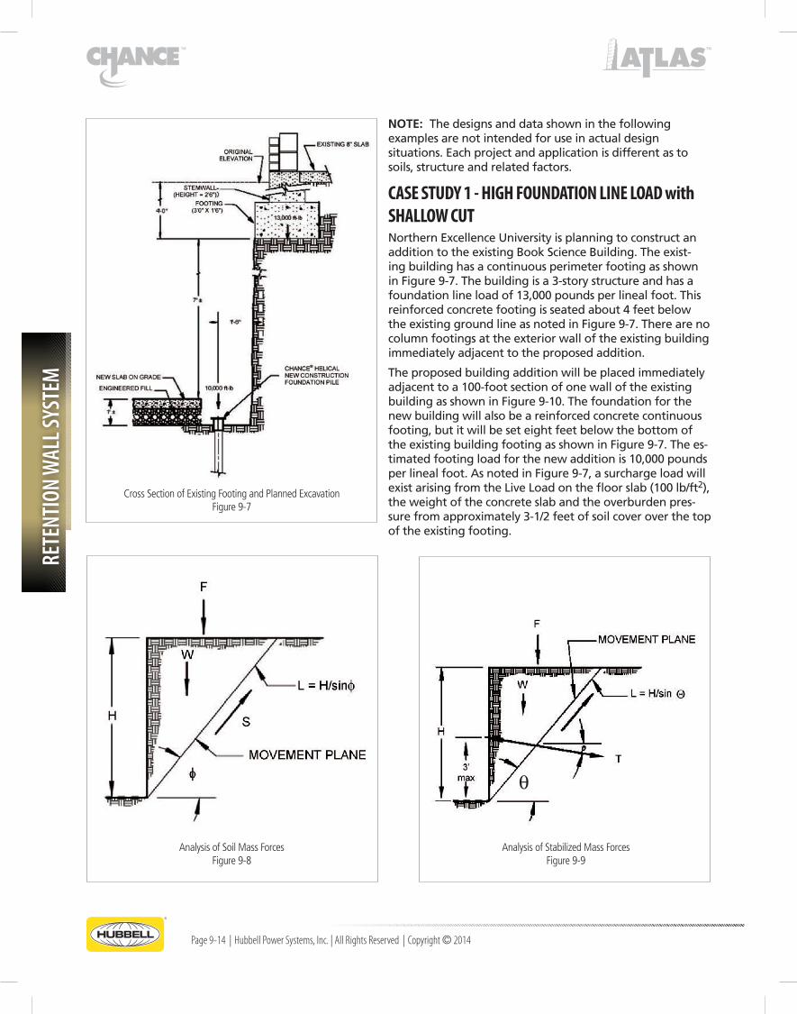
nOTE: The designs and data shown in the following examples are not intended for use in actual design situations.Eachprojectandapplicationisdifferentastosoils, structure and related factors.
CASE STUDY 1 - HIGH FOUNDATION LINE LOAD with SHALLOW CUTNorthernExcellenceUniversityisplanningtoconstructanaddition to the existing Book Science Building. The exist-ing building has a continuous perimeter footing as shown inFigure9-7.Thebuildingisa3-storystructureandhasafoundationlineloadof13,000poundsperlinealfoot.Thisreinforcedconcretefootingisseatedabout4feetbelowtheexistinggroundlineasnotedinFigure9-7.Therearenocolumn footings at the exterior wall of the existing building immediatelyadjacenttotheproposedaddition.
The proposed building addition will be placed immediately adjacenttoa100-footsectionofonewalloftheexistingbuildingasshowninFigure9-10.Thefoundationforthenew building will also be a reinforced concrete continuous footing, but it will be set eight feet below the bottom of theexistingbuildingfootingasshowninFigure9-7.Thees-timatedfootingloadforthenewadditionis10,000poundsperlinealfoot.AsnotedinFigure9-7,asurchargeloadwillexistarisingfromtheLiveLoadonthefloorslab(100lb/ft2),the weight of the concrete slab and the overburden pres-surefromapproximately3-1/2feetofsoilcoveroverthetopof the existing footing.
Cross Section of Existing Footing and Planned ExcavationFigure 9-7
Analysis of Soil Mass ForcesFigure 9-8
Analysis of Stabilized Mass ForcesFigure 9-9
RETENTION WALL SYSTEM
Page 9-15 | Hubbell Power Systems, Inc. | All Rights Reserved | Copyright © 2014
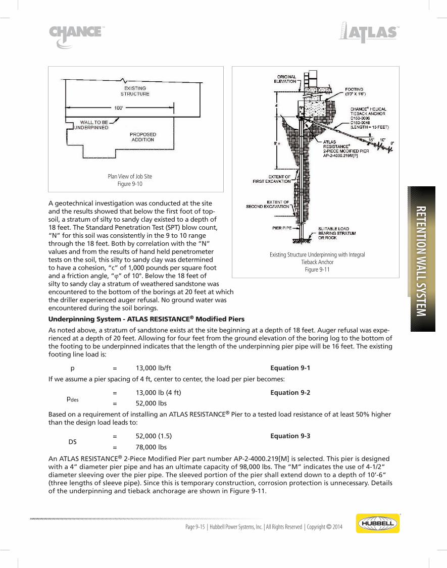
Ageotechnicalinvestigationwasconductedatthesiteand the results showed that below the first foot of top-soil, a stratum of silty to sandy clay existed to a depth of 18feet.TheStandardPenetrationTest(SPT)blowcount,“N”forthissoilwasconsistentlyinthe9to10rangethroughthe18feet.Bothbycorrelationwiththe“N”values and from the results of hand held penetrometer tests on the soil, this silty to sandy clay was determined tohaveacohesion,“c”of1,000poundspersquarefootandafrictionangle,“j”of10°.Belowthe18feetofsilty to sandy clay a stratum of weathered sandstone was encounteredtothebottomoftheboringsat20feetatwhichthedrillerexperiencedaugerrefusal.Nogroundwaterwasencountered during the soil borings.
Underpinning System - ATLAS RESISTANCE® Modified Piers
Asnotedabove,astratumofsandstoneexistsatthesitebeginningatadepthof18feet.Augerrefusalwasexpe-riencedatadepthof20feet.Allowingforfourfeetfromthegroundelevationoftheboringlogtothebottomofthefootingtobeunderpinnedindicatesthatthelengthoftheunderpinningpierpipewillbe16feet.Theexistingfooting line load is:
p = 13,000lb/ft Equation 9-1
Ifweassumeapierspacingof4ft,centertocenter,theloadperpierbecomes:
pdes= 13,000lb(4ft) Equation 9-2
= 52,000lbs
BasedonarequirementofinstallinganATLASRESISTANCE®Piertoatestedloadresistanceofatleast50%higherthan the design load leads to:
DS= 52,000(1.5) Equation 9-3
= 78,000lbs
AnATLASRESISTANCE®2-PieceModifiedPierpartnumberAP-2-4000.219[M]isselected.Thispierisdesignedwitha4”diameterpierpipeandhasanultimatecapacityof98,000lbs.The“M”indicatestheuseof4-1/2“diametersleevingoverthepierpipe.Thesleevedportionofthepiershallextenddowntoadepthof10’-6“(threelengthsofsleevepipe).Sincethisistemporaryconstruction,corrosionprotectionisunnecessary.DetailsoftheunderpinningandtiebackanchorageareshowninFigure9-11.
Plan View of Job SiteFigure 9-10
Existing Structure Underpinning with IntegralTieback Anchor
Figure 9-11

RETE
NTIO
N W
ALL S
YSTE
M
Page 9-16 | Hubbell Power Systems, Inc. | All Rights Reserved | Copyright © 2014
INTEGRATED TIEBACK SYSTEM - CHANCE® Helical Tieback Anchors
Followingtherecommendationofusinganintegratedtiebackwheneverthelineloadexceeds4,000lbs/ft,aCHANCE®HelicalTiebackAnchormustbeselectedforusedwitheachATLASRESISTANCE®2-PieceModifiedPierplacement.Forthissituation,theC1500006TiebackAnchorLeadSectionandC1500048TiebackExtensionwithcoupling and hardware is recommended.
Theinstalledlengthisestimatedtobe15feet.Theinstalledangleis15°downfromhorizontal.Theleadsectionconsistsofone8-inchandone10-inchdiameterplateweldedtoa1-1/2”squaresolidsteelshaft.Installedtorqueisestimatedtobe2,000ft-lbs,minimum.Nocorrosionprotectionisrequiredbecausetheconstructionistempo-rary.
SOIL SCREW® RETENTION WALL SYSTEM
The body mass of soil that would slide along the movement plane if failure were to occur as excavation takes placeisillustratedinFigure9-8.Ifoneusesthesoilpropertiespreviouslylistedwithanassumedfailureplaneangle(q)of51°,thedrivingforceandresistingforcemaybecalculated.InordertoprovideaFactorofSafetyagainstfailureofthebodymass,asinglelineofCHANCE® Helical SOIL SCREW®Anchorswillbeused.Amini-mumFactorofSafetyof2.0isrequiredagainstsuchafailure.(NotethatthetypicaldesignFactorofSafetyforHelical SOIL SCREW®Anchorsrangesfrom1.3to2.0.)AFactorofSafetyof2.0wasselectedbecauseoftheveryhigh foundation line load of the existing footing above the excavation. In conducting the SOIL SCREW®Anchoranalysis,itassumedthattheCHANCE® Helical tieback anchors did not contribute to the holding capacity of the body mass of soil even though the tieback prevents cantilever at the top of the wall.
AlsoshowninFigure9-8istheresistancetomovementsthatoccuralongthemovementplanearisingfromtheshear strength of the soil. This shear strength is made up of both the cohesion and friction acting along that plane.
InFigure9-9thesamebodymassofsoilisshown,butnowthesingleHelicalSOILSCREW®Anchorshownpro-vides additional resistance to sliding that develops along the movement plane. If the installation angle of the Helical SOIL SCREW®Anchoris10°,thenewdrivingforceandnewresistingforcemaybecalculated.
Reinforcement Details for Case Study #1Figure 9-12

RETENTION WALL SYSTEM
Page 9-17 | Hubbell Power Systems, Inc. | All Rights Reserved | Copyright © 2014
Generally,theFactorofSafetyisillustratedbythefollowingequation:
where
FS = RF/(DF-SSCF) Equation 9-4
FS = FactorofSafety
RF = Resisting force
DF = Driving force
SSCF = SOIL SCREW®Anchorcomponentforce
ResistingForce(RF)arisesfromtheshearstrengthofthesoil(candj)alongthemovementplaneandtheHelical SOIL SCREW®Anchorcomponentparalleltothemovementplane.DrivingForce(DF)isthecom-ponentofthesoilbodymass(weight)inthedirectionof the movement plane. Helical SOIL SCREW®AnchorComponentForce(SSCF)isthecomponentofthetotal Helical SOIL SCREW®Anchorholdingcapacity(ultimatecapacity)inthedirectionofthemovementplane. Internal stability analysis as described herein is typically done with commercially available software suchasSNAILZ(Caltrans)orGoldNail(GolderAssoci-ates);seetheCHANCE® Soil Screw® Retention Wall SystemDesignManualforanexample.HelicalSOILSCREW®AnchortensioncapacityiscalculatedwithHeliCAP® Helical Capacity Design Software and input into the stability analysis software.
Forthespecificconditionsdefinedabove,theCHANCE® Helical SOIL SCREW®AnchorLeadSectionC1100692andC1100690Extensionisselected.TheHelical SOIL SCREW®Anchorleadsectionconsistsof8”diameterplatesweldedalongtheentirelengthofa1-1/2”squareshaft.Minimuminstalledlengthis10feet.Installedangleis10°downfromhorizontal.In-stalledtorqueisestimatedtobe1,500ft-lbminimum.The single row of Helical SOIL SCREW®Anchorsissetimmediatelyadjacenttoeachunderpinningpierpipeat a depth of 5 feet below the integrated tieback anchor(thiswillmaintainthe3footmaximumallow-ablebottomcantilever).Nocorrosionprotectionis
required.
SHOTCRETE WALL
Theshotcretewallisatemporaryfacingfortheexcavation.SincethereisaCHANCE®HelicalTiebackAnchorat the top, the wall will be laterally anchored at the pier brackets to allow longer spacing for the single row of Helical SOIL SCREW®Anchors.Thebottomcantilevershouldbe3feet.
The vertical bearing bars are extended from the welded rebar head assembly to the dowels and waler at the topofthewallinordertoaugmenttheweldedwirefabricreinforcing(seeFigures9-13and9-14).
ThetopwallsegmentischeckedforflexureandshearusingthedistributedSOILSCREW®Anchorheadforcesandone-waybeamaction.Two#4reinforcingbarwalersshallbeplacedcontinuouslyalongtheSOILSCREW® Anchorrow.Theselectedwallthicknessis4”.Reinforcingisaweldedwirefabric(WWF6x6W.14orequivalent)spacedmidwayintheshotcretewallata2”nominaldepth.
SOIL SCREW® Anchor Configuration for Case Study #1Figure 9-13

RETE
NTIO
N W
ALL S
YSTE
M
Page 9-18 | Hubbell Power Systems, Inc. | All Rights Reserved | Copyright © 2014
SOIL SCREW® ANCHOR HEAD DESIGN
The shotcrete wall design is critical to the punching shear of the SOIL SCREW®Anchorheadsandflexuralstrength of the all face between the SOIL SCREW® Anchorheads.TheSOILSCREW®Anchorheadforcesareexpectedtobeapproximately1/2ofthetotalSOILSCREW®Anchortensionload.Theshotcretefacingischeckedforflexureandpunchingshearusingtwo-wayslab action. This information is used in the internal stabilityanalysis.Aweldedrebarheadassemblycanbeused at each placement to provide local reinforcement. Itissplicedtothehorizontalwalersandtheverticalbearing bars previously described. To accomplish the proper positioning of the welded rebar head assembly and rebar, the welded wire fabric must be pushed into theinitial2”facecoatofshotcreteapproximately1/2”at each SOIL SCREW®Anchorhead.The4”wallthick-nessandreinforcementselectedaboveareadequate.
Thefirst6feetofsoilisexcavatedandthesoilbodymassisstabilized.Figure9-13showstheinstallationofaCHANCE® Helical SOIL SCREW®Anchor,weldedwirereinforcement, welded rebar head assembly and shot-crete.Notethattheshotcretestopsshortofthebottomof the excavation to allow for splicing the welded wire meshreinforcementandasuitableshotcretejoint.Fig-ure9-14showexcavationtothefinalelevationalongwithcontinuedstabilizationofthesoilmass.Construc-tion of the new foundation begins with the installation ofCHANCE®NewConstructionHelicalPiles.
Excavation to the Final ElevationFigure 9-14

RETENTION WALL SYSTEM
Page 9-19 | Hubbell Power Systems, Inc. | All Rights Reserved | Copyright © 2014
CASE STUDY 2 - LOW FOUNDATION LINE WITH DEEP CUTTheCityofHighHopeisplanningtobuildanewmulti-purposearenathatwillseat8,000people.Thearenawillbelocatedwithinthedowntowndistrict.A20-footdeepcutwillberequiredforthenewconstructiontoprovidesuf-ficientelevationforthearenaseatingyetmaintainalowgroundlevelbuildingprofile.Aportionofthearenawallwillbeimmediatelyadjacenttotheexistinghistoriccitymarketbuilding(seeFigure9-15).Thecitymarketbuildingisasinglestorywarehousethatmeasures60by120feet.Thebackwallofthemarketbuildingwillabutthenewarenawall.Themarketbuildingwasconstructedintheearly1900sandhasanunreinforcedconcretegradebeamfoundation that measures three feet wide by two feet deep. The grade beam, seated three feet below the exist-inggrade,hasalineloadof3,000lbsperlinealfoot.ThegeneralconfigurationofthefootingalongwithinstalledunderpinningandtiebackisshowninFigure9-16.
Ageotechnicalinvestigationconductedatthesitefounda30-footthickstratumofsiltysandbelowapproximatelytwofeet of topsoil and fill material that consisted of silt, sand and cinders.TheStandardPenetrationTest(SPT)blowcount“N”inthissiltysandincreasedwithdepthfromN=13toN=18.Sufficient silt is present in the sand to hold a shallow vertical cut for a short period of time. Below the silty sand stratum atadepthof32feettheboringsencounteredahardglacialtill of clayey sand and gravel. The SPT value recorded were N=50+.BycorrelatingtheNvalues,thefrictionangleofthesiltysand(f)wasestimatedtobe30°.Thegroundwatertable(GWT)waslocatedat15feetwhichmeansdewateringwillberequiredpriortoexcavation.
Based on discussion with the designer and contractor, a deci-sionwasmadetousetheCHANCE® Helical underpinning/shoringtechniqueintheimmediatevicinityofthecitymarket
building. The Helical SOIL SCREW®Anchorswillcontinueforanadditional50feetoneachsideofthemarketbuild-ingastheslopeiscutinabenchedpattern.Beyondthiszone,adequatecleardistanceexiststoback-slopethecutside without providing any wall retaining system.
Underpinning System - ATLAS RESISTANCE® Modified Piers
Asnotedabove,ahardglacialtillexistsatadepthof29feetbelowthebottomofthemarketbuildingfooting.Theestimatedlengthoftheunderpinningpierpipeis32feet.Theexistinglineloadis3,000lb/ft.Althoughthefootinglineloadisrelativelylight,thefactthatthe24”thickfootingisnotreinforcedwilllimitthespacingofthepierstofive feet on center. Based on this spacing, the design load per pier becomes:
Pdes= 3,000lb(5ft) Equation 9-5
= 15,000lbs
BasedontherequirementofinstallingATLASRESISTANCE®ModifiedPierstoatestedloadresistanceofatleast50%higher than the design load leads to:
DS= 15,000(1.5) Equation 9-6
= 22,500lbs
Forthisrequirement,theATLASRESISTANCE®AP-2-3500.165[PA]M2-PieceModifiedPierisselected.Themodifiedpierhasa3-1/2”diameterpierpipeandhasanultimatecapacityof91,000lbs.“M”indicatestheuseof4”diametersleevingoverthepierpipe.Thesleevedportionofthepiershallextenddowntoadepthof21feet(sixlengthsofsleevepipe).“PA”indicatestheproductismanufacturedofmillfinishsteel(plain)withflowcoatedcorrosionpro-tectionofthepierpipe.Sincethisistemporaryconstruction,thecorrosionprotectionisunnecessary;howeverthisproduct is supplied with corrosion protected pipe as standard. Details of the underpinning and tieback anchorage areshowninFigure9-16.
Plan View of Job SiteFigure 9-15

RETE
NTIO
N W
ALL S
YSTE
M
Page 9-20 | Hubbell Power Systems, Inc. | All Rights Reserved | Copyright © 2014
Integrated Tieback System - CHANCE® Helical Tie-back Anchors
Althoughthefootinglineloadislessthanthe4,000lb/ftcriteria,thedepthofthecuttobeshoredis20feet.Thisexceedstherecommended12footlimitationandassuchaCHANCE®HelicalTiebackAnchormustbeselectedforusewitheachmodifiedpierplacement.ForthissituationTypeSS51-1/2”squareshaftLeadSectionandExtensionaretherecommended components.
Theleadsectionconsistsofone8”andone10”diameterplateweldedtoa1-1/2”squareshaft.Minimuminstalledlengthisestimatedtobe15feet.Installedangleis12°downfromhorizontal.Installedtorqueisestimatedtobe1,800ft-lbminimum.Nocorrosionprotectionisrequiredsince the construction is temporary.
SOIL SCREW® Shoring System - CHANCE® Helical SOIL SCREW® Anchors
Becausethedepthofcutis20feetfromgrade(17feetbelowthebottomofthefootingofthemarketbuilding),three Helical SOIL SCREW®Anchorsarerequired.InthiscaseaFactorofSafetyof1.5wasusedbecausetheexist-ing market building is relatively light. In conducting the soilanalysis,itwasassumedthattheCHANCE® Helical Tie-backAnchordoesnotcontributetotheholdingcapacityofthebodymassofsoil.AsinCaseStudy1,internalstabil-ity analysis is typically done with commercially available softwaresuchasSNAILZ(Caltrans)orGoldNail(GolderAssociates),andSOILSCREW®AnchortensioncapacityiscalculatedwithHeliCAP® Helical Capacity Design Software
andinputintothestabilityanalysissoftware.Inthisproject,theshearstrengthisfromthefrictionalnatureofthecohesionlesssoil(siltysand)anditsmagnitudeisrelatedtothefrictionangle(j=30°inthiscase).
AsdescribedintheCHANCE® SOIL SCREW®RetentionWallSystemDesignManual,SOILSCREW®Anchorsaddtotheresistingforcealongthemovementplane.Inthiscase,however,theindicatedforce(T)istheresultantofallthreerows of Helical SOIL SCREW®Anchors.PlacementofthethreerowsofHelicalSOILSCREW®AnchorsisshowninFig-ure9-18.Thevaluefortheultimateholdingcapacityrequired(includingtheFactorofSafety)is:
T = T1+T2+T3 Equation 9-7
The results of extensive testing of soil nail walls indicate that the top row of soil nails or screws is most heavily loadedwiththesuccessivelylowerrowshavinglesserholdingcapacityrequirements.Thefollowingaretherecom-mendedCHANCE® Helical SOIL SCREW®Systemsforthisproject:
• SOILSCREW®AnchorRow#1(T1):C2200691LeadandtwoC1100689Extensions.TheSOILSCREW®Anchorhascontinuouslyspaced8”diameterplatesalongtheentirelengthofa1-1/2”solidsquaresteelshaft.TheSOIL SCREW®Anchorwillbeinstalledtoaminimumlengthof19feet,10°downfromhorizontalandtoanestimatedtorqueof2,500ft-lbs.
• SOILSCREW®AnchorRow#2(T2):C2200691LeadandoneC1100689Extension.TheSOILSCREW®Anchorhascontinuouslyspaced8”diameterplatesalongtheentirelengthofa1-1/2”solidsquaresteelshaft.TheSOIL SCREW®Anchorwillbeinstalledtoaminimumlengthof14feet,10°downfromhorizontalandtoanestimatedtorqueof1,800ft-lbs.
• SOILSCREW®AnchorRow#3(T3):C1100692LeadandC1100690Extension.TheSOILSCREW®Anchorhascontinuouslyspaced8”diameterplatesalongtheentirelengthofa1-1/2”solidsquaresteelshaft.TheSOILSCREW®Anchorwillbeinstalledtoaminimumlengthof10feet,10°downfromhorizontalandtoanesti-matedtorqueof1,000ft-lbs.
SOIL SCREW Configuration for Case Study #2Figure 9-16

RETENTION WALL SYSTEM
Page 9-21 | Hubbell Power Systems, Inc. | All Rights Reserved | Copyright © 2014
Excavation and StabilizationFigure 9-18
Reinforcement Details for Case Study #2Figure 9-17

RETE
NTIO
N W
ALL S
YSTE
M
Page 9-22 | Hubbell Power Systems, Inc. | All Rights Reserved | Copyright © 2014
Shotcrete Wall
Theshotcretewallisatemporaryfacingfortheexcavation.SincethesoilanalysisassumedthattheCHANCE® Helical TiebackAnchorsdonotcontributetotheholdingcapacityofthebodymassofsoil(seeFigure9-8),theCHANCE® Helical SOIL SCREW®Anchorsweredesignedtoholdthetotalbodymass.Thebottomcantilevershouldbelimitedto2/3ofthetypicalspacingfortheSOILSCREW®Anchorrow,butshouldnotexceed3feet.Inthiscasethecantileveris3 feet.
Vertical bearing bars are extended from the welded rebar head assemblies at the upper row of SOIL SCREW®Anchorstothedowelsandwaleratthetopofthewallinordertoaugmenttheselectedshotcretewallthickness(5”).Weldedwirefabricreinforcing(WWF6x6W2.9orequivalent)isspacedmidwaywithintheshotcretewallata2-1/2”nominaldepth.ThetopwallsegmentischeckedforflexureandshearusingthedistributedSOILSCREW®Anchorheadforcesandone-waybeamaction.Two#4reinforcingbarwalersareplacedcontinuouslyalongeachSOILSCREW®Anchorrow(seeFigures9-17and9-18).
SOIL SCREW® Anchor Head Design
The SOIL SCREW®Anchorheadforcesareexpectedtobeapproximately1/2oftheSOILSCREW®Anchortensionload.Theshotcretefacingischeckedforflexureandpunchingshearusingtwo-wayslabaction.Thisinformationisusedintheinternalstabilityanalysis.Awallplatecouldhavebeenplacedatthewallfacetomaximizepunchingshear resistance, but in this example a welded rebar head assembly that includes a wall plate is placed on each Heli-cal SOIL SCREW®AnchoratthemiddleoftheshotcretewallasshowninFigure9-18(refertoSOILSCREW®AnchorWallAccessoriesfordetailsoftheweldedrebarheadassembly).TheweldedrebarheadassemblyshallbesplicedtothehorizontalwalersateachrowofHelicalSOILSCREW®Anchorsandtotheverticalbearingbarsbetweentheupper row of Helical SOIL SCREW®Anchorsandthedowelsatthepierbrackets.Toproperlypositionandembedtheweldedrebarheadassemblyandrebar,theweldedwirefabricmustbepushedintotheinitial2-1/2”facecoatofshotcreteapproximately1/2”ateachSOILSCREW®Anchorhead.The5”wallthicknessandreinforcementdescribedaboveareadequate.
References:
1. AASHTOHighwaySubcommitteeonBridgesandStructures,ManualonFoundationInvestigations,AmericanAssociationofStateHighwayandTransportationOfficials,1978.
2. FederalHighwayAdministrationPublicationNo.FHWA-SA93-026,RecommendationsClouterre,EnglishTranslation,1993.
3. FederalHighwayAdministrationPublicationNo.FHWA-SA-96-069,ManualforDesignandConstructionMonitoringofSoilNailWalls,1996.
4. FederalHighwayAdministrationPublicationNo.FHWA-SA-96-071,MechanicallyStabilizedEarthWallsandReinforcedSoilSlopesDesignandConstructionGuidelines,1996.
5. FederalHighwayAdministrationPublicationNo.FHWA-SA-96-072,Corrosion/DegradationofSoilReinforcementforMechanicallyStabilizedEarthWallsandReinforcedSoilSlopes,1996.