RESTORING CRANKSHAFT ALIGNMENT: A CASE · PDF filepage 1 of 20 RESTORING CRANKSHAFT ALIGNMENT:...
20
page 1 of 20 RESTORING CRANKSHAFT ALIGNMENT: A CASE HISTORY Mark L. Deutscher, P.Eng. Brian C. Howes, M.Sc., P.Eng. Canadian Design Services Representative Chief Engineer Beta Machinery Analysis Ltd., Calgary, AB, Canada, T3C 0J7 ABSTRACT Foundations under reciprocating equipment will often deteriorate over time. When this happens, and the foundation subsides, the web deflections in the machinery crankshafts can go beyond OEM specifications. In the limit, excessive web deflections can cause crankshaft fatigue failures. A common approach to restoring the crankshaft web deflections is a very costly re- grout of the machine. Not only is this type of foundation work costly, it will normally require significant downtime and therefore lost production. This paper describes an alternative to foundation restoration work when the current foundation is stable. A case history illustrates the success of this alternative approach. SUMMARY During a regular service interval of a De Laval HV8-2C engine and two throw compressor, it was discovered that the engine crankshaft web deflections on the throw nearest the flywheel were beyond manufacturer’s specifications. Suspecting that this was a sign of a foundation problem, the owner contacted suppliers for quotes to repair the foundation. After a preliminary review of the installation we agreed that the best way to correct the alignment was to re-do the foundation. However, the owner’s crystal ball said that this piece of equipment would likely not be required after 3 to 5 years. A compromise solution was offered involving shimming between the lower engine and compressor skid beams and the foundation to straighten the machine. The shimming approach might have turned out to be a temporary fix, but the relative cost versus renewing the foundation was attractive. The first assessment of the unit determined that indeed the foundation had deteriorated and that the anchor bolt condition was poor. It was surmised, by examining the foundation and anchor bolt wear pattern, that the back of the compressor and, to a lesser degree, the front of the engine had worn down into the grout bed. A shimming plan was devised and implemented, restoring the crankshaft web deflections to acceptable numbers. We also recommended increasing the stretch length of the anchor bolts. A second visit was made to determine if the shims were remaining effective. Some changes were made as there had been some bedding of the shims into the rough surface of the grout. All of the anchor bolts were re-torqued. In a recent examination of the unit after over three years of uninterrupted service, unit vibrations were found to be good and all anchor bolts have remained tight. The hot engine crankshaft web deflections and coupling alignment were acceptable with no significant change. The unit can continue to run as is. http://www.BetaMachinery.com
Transcript of RESTORING CRANKSHAFT ALIGNMENT: A CASE · PDF filepage 1 of 20 RESTORING CRANKSHAFT ALIGNMENT:...
page 1 of 20
RESTORING CRANKSHAFT ALIGNMENT: A CASE HISTORY
Mark L. Deutscher, P.Eng. Brian C. Howes, M.Sc., P.Eng. Canadian Design Services Representative Chief Engineer
Beta Machinery Analysis Ltd., Calgary, AB, Canada, T3C 0J7
ABSTRACT Foundations under reciprocating equipment will often deteriorate over time. When this happens, and the foundation subsides, the web deflections in the machinery crankshafts can go beyond OEM specifications. In the limit, excessive web deflections can cause crankshaft fatigue failures. A common approach to restoring the crankshaft web deflections is a very costly re-grout of the machine. Not only is this type of foundation work costly, it will normally require significant downtime and therefore lost production. This paper describes an alternative to foundation restoration work when the current foundation is stable. A case history illustrates the success of this alternative approach.
SUMMARY During a regular service interval of a De Laval HV8-2C engine and two throw compressor, it was discovered that the engine crankshaft web deflections on the throw nearest the flywheel were beyond manufacturer’s specifications. Suspecting that this was a sign of a foundation problem, the owner contacted suppliers for quotes to repair the foundation. After a preliminary review of the installation we agreed that the best way to correct the alignment was to re-do the foundation. However, the owner’s crystal ball said that this piece of equipment would likely not be required after 3 to 5 years. A compromise solution was offered involving shimming between the lower engine and compressor skid beams and the foundation to straighten the machine. The shimming approach might have turned out to be a temporary fix, but the relative cost versus renewing the foundation was attractive. The first assessment of the unit determined that indeed the foundation had deteriorated and that the anchor bolt condition was poor. It was surmised, by examining the foundation and anchor bolt wear pattern, that the back of the compressor and, to a lesser degree, the front of the engine had worn down into the grout bed. A shimming plan was devised and implemented, restoring the crankshaft web deflections to acceptable numbers. We also recommended increasing the stretch length of the anchor bolts. A second visit was made to determine if the shims were remaining effective. Some changes were made as there had been some bedding of the shims into the rough surface of the grout. All of the anchor bolts were re-torqued. In a recent examination of the unit after over three years of uninterrupted service, unit vibrations were found to be good and all anchor bolts have remained tight. The hot engine crankshaft web deflections and coupling alignment were acceptable with no significant change. The unit can continue to run as is.
http://www.BetaMachinery.com
page 2 of 20
KEY POINTS: • Improperly installed anchors, no stretch, loss of tension, will invariably cause problems. 10
to 15 bolt diameters should be a minimum target to achieve sufficient stretch length, more won’t hurt. Note: It is good practice to stagger the embedment of the anchors to reduce the chance of a foundation crack along the base of the anchor bolts. Use hardened steel washers for torquing accuracy. Critical installations should consider anchors with bolt stretch indicators. {A work-a-day technique to see if torque has been lost: mark nut and equipment mounting flange with paint or scribe mark, loosen nut, clean threads and surfaces and lubricate according to torque specification used, tighten to prescribed torque, observe position of nut after compared to before.}
• It is possible and practical to salvage an alignment by shimming between the grout surface and the machine base when the problem is due to localized deterioration of the connections. It is important that basic foundation integrity be assured and that anchor bolt condition is serviceable. In this case the initial reluctance to attempt a shim alignment of this nature because of concerns with short term stability proved unfounded.
• Shimming proved to be very cost-effective when compared to the cost of a complete renewal
of the foundation.
1. INTRODUCTION It is almost a rule that foundation problem is never declared until some other machine problem like high vibration or a bad crankshaft web deflection is encountered. Just another example of the “If it’s not broke, don’t fix it” rule. Typical foundation repairs by that time are often extensive and require significant downtime. This paper presents a case study where shims between the engine and compressor skid and the grout bed were used to restore an engine crankshaft alignment. Typically, foundation and anchor bolt replacements would be recommended for a machine in this condition. In this case a lesser approach was entertained because it was a low cost investment and the machine was nearing the end of its useful life.
2. EQUIPMENT AND FOUNDATION DETAILS Equipment: De Laval HV8-C2 natural gas engine and two throw compressor The engine is an eight cylinder Vee configuration with power cylinder pairs in line with each other via master/articulated connecting rod arrangement. Maximum engine speed is 600 RPM. Engine horizontal primary forces are reduced by the use of dual counter-balancers running at 2x engine speed. The lower part of the engine is a built up structure of welded steel sections. The
http://www.BetaMachinery.com

page 3 of 20
primary members are 30” tall wide flange beams which form the sides of the lower crankcase/sump and base.
Figure 1: Picture of Engine-Compressor, compressor in foreground. Note the beautifully polished valve covers on the engine.
The compressor has two horizontally opposed offset throws. It is operating in two staged configuration with a 15 ½” dia. cylinder on first stage, and a 12” dia. cylinder on second stage. The compressor sits on top of a 14” tall wide flange beam structure welded to the rear of the lower engine metalwork. Ancillary equipment is set on a lighter structure formed of 12” wide flange beams welded to the front of the engine metalwork. See Figure 2 for a sketch.
Figure 2: Side view of engine base, compressor sub-base and ancillary equipment base
http://www.BetaMachinery.com
page 4 of 20
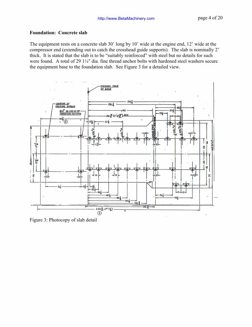
Foundation: Concrete slab The equipment rests on a concrete slab 30’ long by 10’ wide at the engine end, 12’ wide at the compressor end (extending out to catch the crosshead guide supports). The slab is nominally 2’ thick. It is stated that the slab is to be “suitably reinforced” with steel but no details for such were found. A total of 29 1¼″ dia. fine thread anchor bolts with hardened steel washers secure the equipment base to the foundation slab. See Figure 3 for a detailed view.
Figure 3: Photocopy of slab detail
http://www.BetaMachinery.com
page 5 of 20
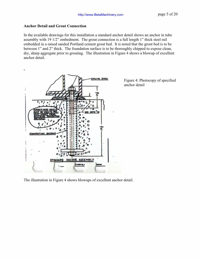
Anchor Detail and Grout Connection In the available drawings for this installation a standard anchor detail shows an anchor in tube assembly with 19 1/2” embedment. The grout connection is a full length 1” thick steel rail embedded in a raised sanded Portland cement grout bed. It is noted that the grout bed is to be between 1” and 2” thick. The foundation surface is to be thoroughly chipped to expose clean, dry, sharp aggregate prior to grouting. The illustration in Figure 4 shows a blowup of excellent anchor detail.
Figure 4: Photocopy of specified anchor detail
The illustration in Figure 4 shows blowups of excellent anchor detail.
http://www.BetaMachinery.com
page 6 of 20
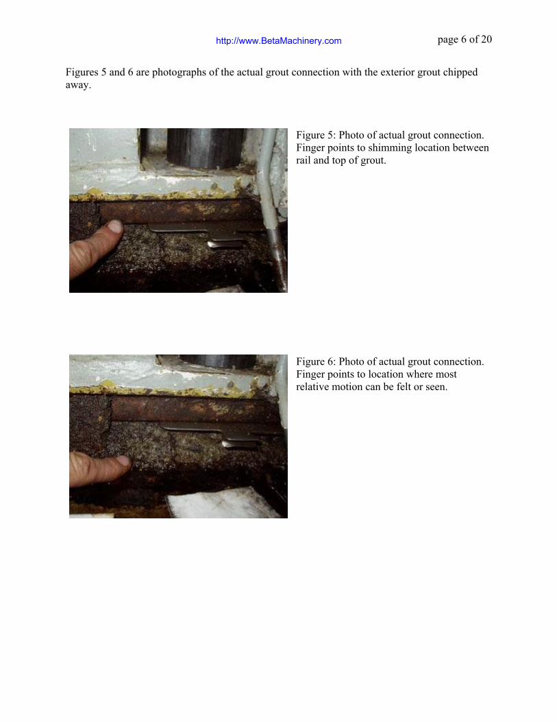
Figures 5 and 6 are photographs of the actual grout connection with the exterior grout chipped away.
Figure 5: Photo of actual grout connection. Finger points to shimming location between rail and top of grout.
Figure 6: Photo of actual grout connection. Finger points to location where most relative motion can be felt or seen.
http://www.BetaMachinery.com

page 7 of 20
3. INVESTIGATION HISTORY
July 2, 1999
The personnel operating the 28 year old machine had noted signs of foundation degradation but it wasn’t until engine web deflections were measured during a plant turnaround that a concern was raised. The problem was a 5.5 thou (Hot) on engine throw number four (nearest the flywheel), well in excess of De Laval specifications. The coupling alignment was corrected and loose left hand side anchor bolts along the engine were tightened. This work reduced the web deflection on throw four to 3.75 thou, still greater than specifications. At that point we were contacted to conduct an assessment of the machine foundation. Findings:
• Foundation slab itself is in good shape. • Grout to foundation slab connection appears to be in poor shape with relative motion
visible at several locations. This is most noticeable on engine left hand side and compressor right hand side. Oil can be seen squirting out of cracks in the grout. NOTE: De Laval installation specification calls for sand with Portland cement or approved epoxy grout. The grout used was relatively coarse sand and Portland cement.
• Engine vibration is reasonable. Dominant component is at 2x run speed, with the engine moving 2.3 mils p-p horizontally at a point near the front, with much less vibration at the rear of the engine. Areas of higher vertical vibration amplitude at the equipment base correspond to areas of higher horizontal vibration of the engine.
Recommendations:
• Further investigation should check un-coupled web deflections and examine the crankshaft main bearings on either side of engine throw #4 for signs of problems such as uneven wear or loading.
• Ideally, repair the engine and compressor grout connection. Adjustable chocks and epoxy grout should be used. Repair to remove contaminated concrete at grout interface.
• Alternatively, our chief engineer suggests that it may be possible to use a steel shim at the grout to steel interface to restore the engine alignment.
Follow up:
• Un-coupling the compressor from the engine does not change web deflection. • Bearing condition is good. • Owner seeks quotes on foundation repairs, pricey in capital outlay and lost production,
especially since unit is nearing end of its useful life. Although the owner is skeptical about the workability of installing shims directly to the grout they will discuss a shimming option.
http://www.BetaMachinery.com

page 8 of 20
August 4, 1999
This visit included: • Vibration check. • Anchor bolt inspection, visual, and soft foot check and correction. • As found web deflection check. • Trim alignment of the engine and compressor bases as well as a coupling alignment. • As left web deflection check.
Prior to the site visit we requested that the grout lip be removed to expose the rail and grout down to the top of the concrete slab in the areas beneath the anchor bolts. Findings:
• Engine and compressor vibration satisfactory. But varying degrees of relative motion was seen and felt at the grout to slab interface, greatest at the rear of the compressor.
• Anchor bolts were found tight. However, all the hardened washers under nuts showed significant wear and fretting. We believe this to point to long periods in which the anchor bolts were loose. Contrary to design all hold down anchors were found fully embedded into the concrete foundation. Available stretch length estimated to be less than 3”. Some of the bolts would come from hand tight to full torque in less than ¼ of a turn.
• The cold, as found web deflection was -4 thou at engine throw #4. Throw 4 is closest to flywheel and indicates that the throw was tight at the bottom. See Figure 7 for a photo. This was consistent with our developing hypothesis that motion at the front of the engine and rear of the compressor had, when ever the anchor bolts were loose at least, worn away at the grout and sagged downwards.
• Soft feet of up to 26 thou were found, tending to be highest at the rear of the compressor and front of the engine. Corrections were made on the worst soft feet where it was possible to insert shims. Anchor bolts and nuts were cleaned, lubricated and re-installed to a torque value of 480ft*lbs. Web deflection reduced to -3.75 mils.
• The web deflection at throw four, nearest the coupling, was reduced from -4 mils to -1.75 mils by leaving the first four anchors on each side of the front of the engine tight, loosening all the other anchors and jacking up the compressor sub base. Progressively thicker shims were installed to the rear of the compressor base. The rear of the compressor base was raised approximately 100 mils. The shims were installed in the gap which opened up between the bottom of the rail and the top of the grout surface. Table 1 below shows the “as left” web deflection after shimming.
Table 1: “As left” cold web deflections.
Engine throw # Web deflection at bottom measured from right (mils)1 +0.5 2 +1.0 3 +1.5 4 -1.0, (-1.75 measured from left)
According to De Laval information available on-site these web deflections are within specification of a maximum of -3 mils at web nearest the flywheel. Web deflections up
to -5.75 were reported prior to the field visit
http://www.BetaMachinery.com

page 9 of 20
Figure 7: View of engine crankshaft throw #4 with web deflection gauge installed
• The compressor and engine were found to be in good cold alignment prior to the foundation trimming. The compressor was realigned after the foundation trimming. In discussion with owner representatives the compressor was left approximately 10 mils higher than the engine. In both cases the reverse face alignment method was used.
Recommendations:
• Be prepared to conduct a quarterly detailed anchor bolt inspection. • Lengthen studs to obtain some stretch length. • At first opportunity check and report Hot web deflections and Hot engine to compressor
alignment. Re-alignment may be necessary. Follow up:
• Site visit planned for next practical opportunity to check hot web deflections and re-adjust alignment if necessary.
August 18, 1999
This visit included:
• Anchor bolt inspection, visual, and soft foot check. • As found Hot and Cold web deflection checks. • Trim alignment of the engine base. • Coupling alignment check. • As left web deflection check.
Findings:
• Hot web deflection at engine throw four was four mils, over the 3 mils Hot target. • Operators reported loosening of anchor bolts. Anchor extensions had not been installed.
http://www.BetaMachinery.com
page 10 of 20
• Hot engine to compressor coupling alignment was good. • Soft feet check, the worst was 5 thou at anchor 4 right. This reduced to 2 thou when
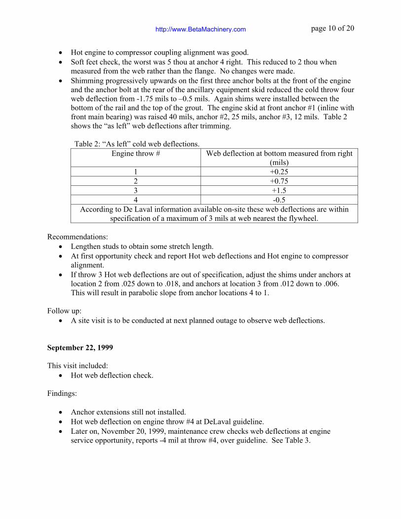
measured from the web rather than the flange. No changes were made. • Shimming progressively upwards on the first three anchor bolts at the front of the engine
and the anchor bolt at the rear of the ancillary equipment skid reduced the cold throw four web deflection from -1.75 mils to –0.5 mils. Again shims were installed between the bottom of the rail and the top of the grout. The engine skid at front anchor #1 (inline with front main bearing) was raised 40 mils, anchor #2, 25 mils, anchor #3, 12 mils. Table 2 shows the “as left” web deflections after trimming.
Table 2: “As left” cold web deflections.
Engine throw # Web deflection at bottom measured from right (mils)
1 +0.25 2 +0.75 3 +1.5 4 -0.5
According to De Laval information available on-site these web deflections are within specification of a maximum of 3 mils at web nearest the flywheel.
Recommendations:
• Lengthen studs to obtain some stretch length. • At first opportunity check and report Hot web deflections and Hot engine to compressor
alignment. • If throw 3 Hot web deflections are out of specification, adjust the shims under anchors at
location 2 from .025 down to .018, and anchors at location 3 from .012 down to .006. This will result in parabolic slope from anchor locations 4 to 1.
Follow up:
• A site visit is to be conducted at next planned outage to observe web deflections.
September 22, 1999
This visit included: • Hot web deflection check.
Findings:
• Anchor extensions still not installed. • Hot web deflection on engine throw #4 at DeLaval guideline. • Later on, November 20, 1999, maintenance crew checks web deflections at engine
service opportunity, reports -4 mil at throw #4, over guideline. See Table 3.
http://www.BetaMachinery.com
page 11 of 20
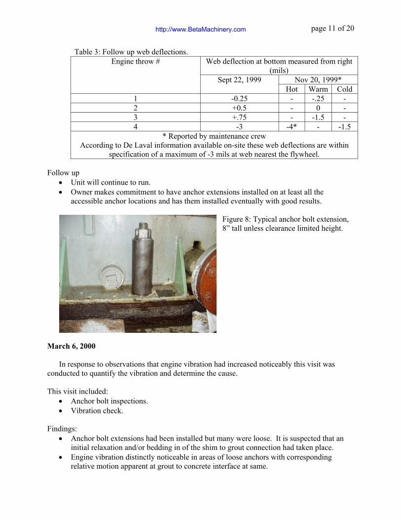
Table 3: Follow up web deflections. Web deflection at bottom measured from right
(mils) Nov 20, 1999*
Engine throw #
Sept 22, 1999 Hot Warm Cold
1 -0.25 - -.25 - 2 +0.5 - 0 - 3 +.75 - -1.5 - 4 -3 -4* - -1.5
* Reported by maintenance crew According to De Laval information available on-site these web deflections are within
specification of a maximum of -3 mils at web nearest the flywheel.
Follow up • Unit will continue to run. • Owner makes commitment to have anchor extensions installed on at least all the
accessible anchor locations and has them installed eventually with good results.
Figure 8: Typical anchor bolt extension, 8” tall unless clearance limited height.
March 6, 2000 In response to observations that engine vibration had increased noticeably this visit was
conducted to quantify the vibration and determine the cause.
This visit included: • Anchor bolt inspections. • Vibration check.
Findings:
• Anchor bolt extensions had been installed but many were loose. It is suspected that an initial relaxation and/or bedding in of the shim to grout connection had taken place.
• Engine vibration distinctly noticeable in areas of loose anchors with corresponding relative motion apparent at grout to concrete interface at same.
http://www.BetaMachinery.com
page 12 of 20
Recommendations:
• Re-torque all anchors. • At next practical opportunity verify that vibration is reduced as expected. • Check web deflections and coupling alignment.
Follow up:
• The anchors were re-torqued with good results, vibration reduced. • Will continue to run until next planned shut opportunity.
May 1, 2000 During a planned shut down a site visit was conducted to verify vibration reduction and
check web deflections and coupling alignment.
This visit included: • Anchor bolt inspections. • Vibration check. • Hot web deflection check. • Coupling alignment check.
Findings:
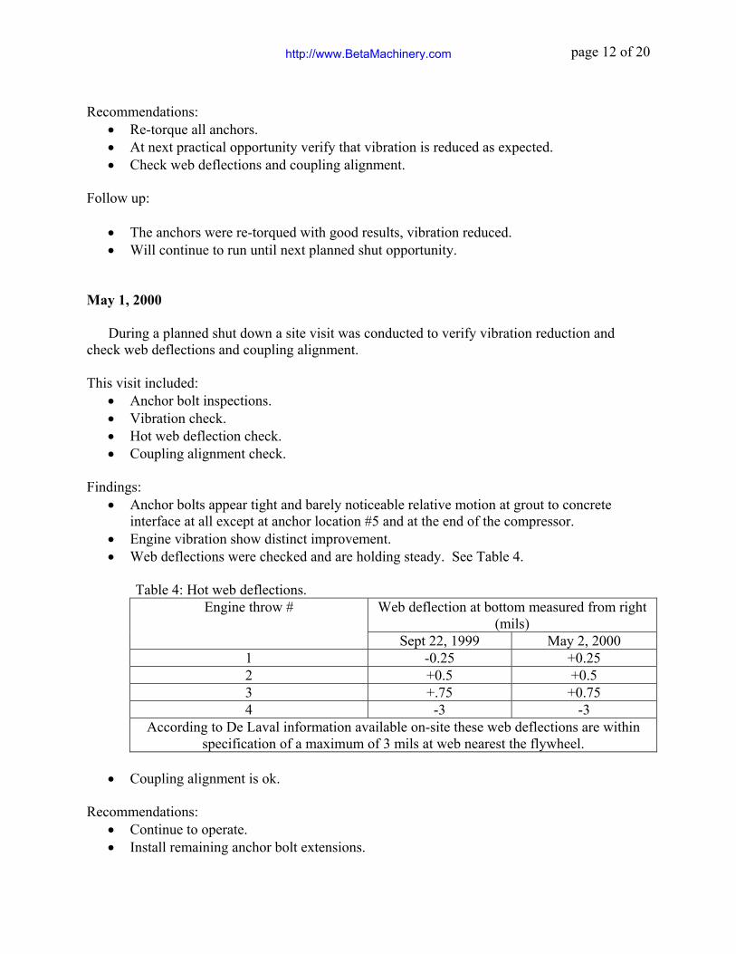
• Anchor bolts appear tight and barely noticeable relative motion at grout to concrete interface at all except at anchor location #5 and at the end of the compressor.
• Engine vibration show distinct improvement. • Web deflections were checked and are holding steady. See Table 4.
Table 4: Hot web deflections. Web deflection at bottom measured from right
(mils) Engine throw #
Sept 22, 1999 May 2, 2000 1 -0.25 +0.25 2 +0.5 +0.5 3 +.75 +0.75 4 -3 -3
According to De Laval information available on-site these web deflections are within specification of a maximum of 3 mils at web nearest the flywheel.
• Coupling alignment is ok.
Recommendations: • Continue to operate. • Install remaining anchor bolt extensions.
http://www.BetaMachinery.com

page 13 of 20
• At convenient opportunity arrange visit to install slight shimming change under anchors at location #5.
• After six months, check anchor bolts condition, web deflection at engine throw #4 and coupling alignment.
Follow up: All quiet until May 2003. May 23, 2003
The unit has run reliably since last visit. It is due to be shut down indefinitely. This
inspection is to check things out and provide information for future planning.
This visit included: • Anchor bolt inspections. • Vibration check. • Hot web deflection check. • Coupling alignment check.
Findings:
• Anchor bolts are all tight with results very similar to last inspections. For the most part barely noticeable relative motion at grout to concrete interface at all except at anchor location #5 and at the end of the compressor.
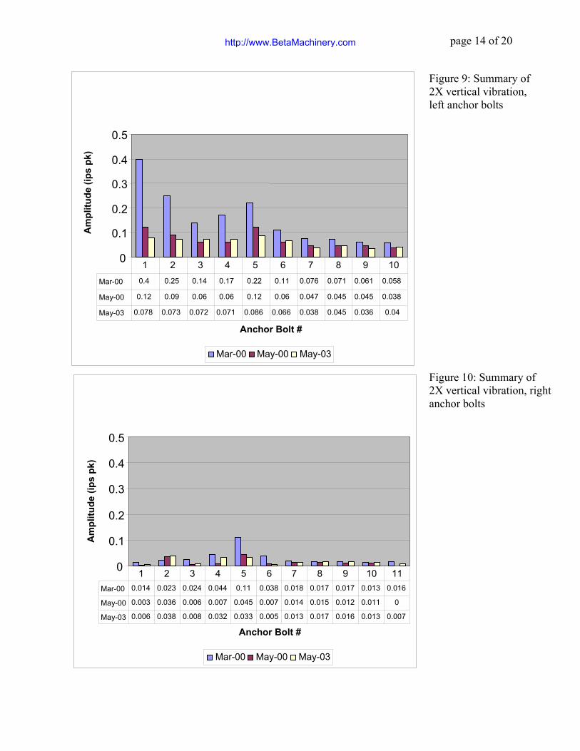
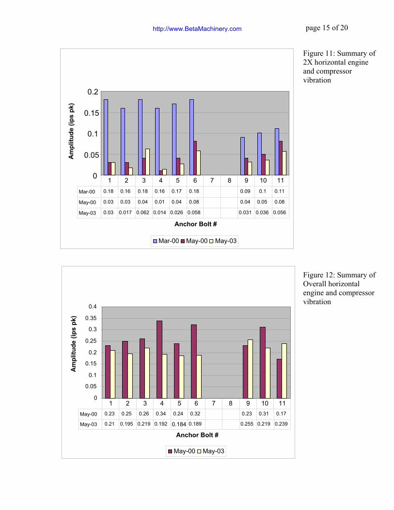
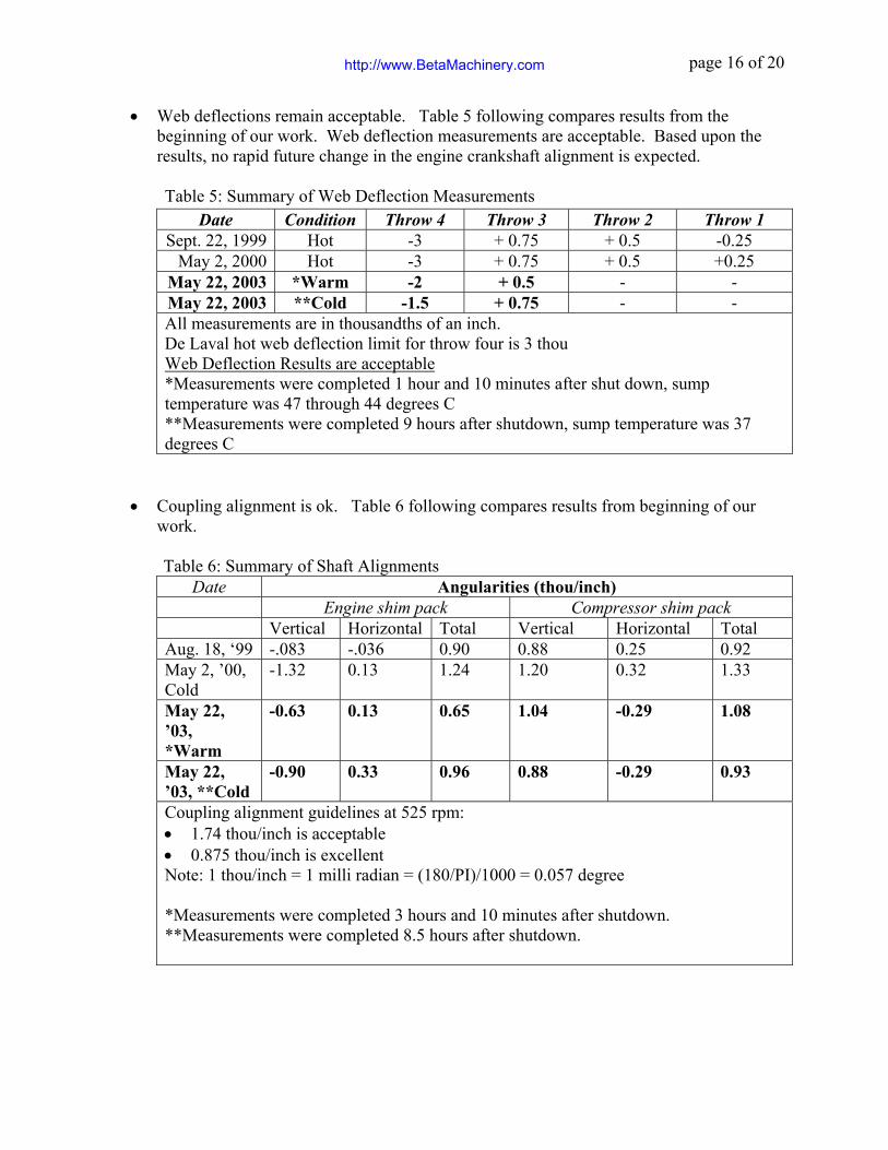
• Engine vibration remains at good levels, the following plots on Figures 9 through 12 compare vibration from the last three visits.
http://www.BetaMachinery.com
page 14 of 20
0
0.1
0.2
0.3
0.4
0.5
Anchor Bolt #
Am
plitu
de (i
ps p
k)
Mar-00 May-00 May-03
Mar-00 0.4 0.25 0.14 0.17 0.22 0.11 0.076 0.071 0.061 0.058
May-00 0.12 0.09 0.06 0.06 0.12 0.06 0.047 0.045 0.045 0.038
May-03 0.078 0.073 0.072 0.071 0.086 0.066 0.038 0.045 0.036 0.04
1 2 3 4 5 6 7 8 9 10
0
0.1
0.2
0.3
0.4
0.5
Anchor Bolt #
Am
plitu
de (i
ps p
k)
Mar-00 May-00 May-03
Mar-00 0.014 0.023 0.024 0.044 0.11 0.038 0.018 0.017 0.017 0.013 0.016
May-00 0.003 0.036 0.006 0.007 0.045 0.007 0.014 0.015 0.012 0.011 0
May-03 0.006 0.038 0.008 0.032 0.033 0.005 0.013 0.017 0.016 0.013 0.007
1 2 3 4 5 6 7 8 9 10 11
Figure 9: Summary of 2X vertical vibration, left anchor bolts
Figure 10: Summary of 2X vertical vibration, right anchor bolts
http://www.BetaMachinery.com
page 15 of 20
0
0.05
0.1
0.15
0.2
Anchor Bolt #
Am
plitu
de (i
ps p
k)
Mar-00 May-00 May-03
Mar-00 0.18 0.16 0.18 0.16 0.17 0.18 0.09 0.1 0.11
May-00 0.03 0.03 0.04 0.01 0.04 0.08 0.04 0.05 0.08
May-03 0.03 0.017 0.062 0.014 0.026 0.058 0.031 0.036 0.056
1 2 3 4 5 6 7 8 9 10 11
0 0.05
0.1 0.15
0.2 0.25
0.3 0.35
0.4
Anchor Bolt #
Am
plitu
de (i
ps p
k)
May-00 May-03
May-00 0.23 0.25 0.26 0.34 0.24 0.32 0.23 0.31 0.17
May-03 0.21 0.195 0.219 0.192 0.184 0.189 0.255 0.219 0.239
1 2 3 4 5 6 7 8 9 10 11
Figure 11: Summary of 2X horizontal engine and compressor vibration
Figure 12: Summary of Overall horizontal engine and compressor vibration
http://www.BetaMachinery.com
page 16 of 20
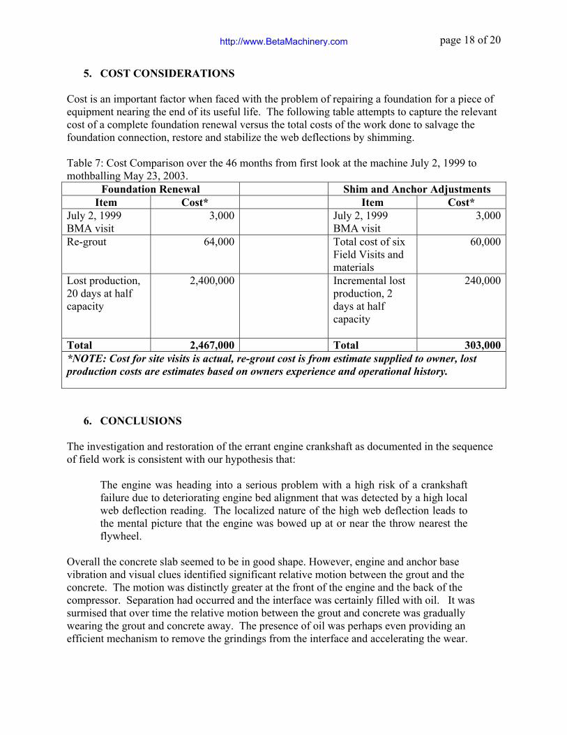
• Web deflections remain acceptable. Table 5 following compares results from the beginning of our work. Web deflection measurements are acceptable. Based upon the results, no rapid future change in the engine crankshaft alignment is expected.
Table 5: Summary of Web Deflection Measurements
Date Condition Throw 4 Throw 3 Throw 2 Throw 1 Sept. 22, 1999 Hot -3 + 0.75 + 0.5 -0.25
May 2, 2000 Hot -3 + 0.75 + 0.5 +0.25 May 22, 2003 *Warm -2 + 0.5 - - May 22, 2003 **Cold -1.5 + 0.75 - - All measurements are in thousandths of an inch. De Laval hot web deflection limit for throw four is 3 thou Web Deflection Results are acceptable *Measurements were completed 1 hour and 10 minutes after shut down, sump temperature was 47 through 44 degrees C **Measurements were completed 9 hours after shutdown, sump temperature was 37 degrees C
• Coupling alignment is ok. Table 6 following compares results from beginning of our
work.
Table 6: Summary of Shaft Alignments Date Angularities (thou/inch)
Engine shim pack Compressor shim pack Vertical Horizontal Total Vertical Horizontal Total Aug. 18, ‘99 -.083 -.036 0.90 0.88 0.25 0.92 May 2, ’00, Cold
-1.32 0.13 1.24 1.20 0.32 1.33
May 22, ’03, *Warm
-0.63 0.13 0.65 1.04 -0.29 1.08
May 22, ’03, **Cold
-0.90 0.33 0.96 0.88 -0.29 0.93
Coupling alignment guidelines at 525 rpm: • 1.74 thou/inch is acceptable • 0.875 thou/inch is excellent Note: 1 thou/inch = 1 milli radian = (180/PI)/1000 = 0.057 degree *Measurements were completed 3 hours and 10 minutes after shutdown. **Measurements were completed 8.5 hours after shutdown.
http://www.BetaMachinery.com

page 17 of 20
Recommendations: • This unit may continue to operate if required. • Continue to check anchor bolt condition periodically. • Check web deflections at suitable maintenance opportunities.
Follow up: Unit to be mothballed and will remain shutdown indefinitely.
4. MEASUREMENTS The investigation and repair work was guided by the information provided by the following:
• Visual assessment of foundation condition, also crankshaft main bearing condition. • Vibration measurements: engine horizontal at crank height and vertical vibration near anchor
locations. • Soft foot checks at interface to foundation. • Relative motion assessments at interface of sub-bases to rail and rail to grout and grout to
concrete. • Reverse face coupling alignment method was used to directly obtain coupling angularities
and was particularly useful because piping under the coupling limited clearance. A spread sheet was used to do the shim calculations which were more complicated than most laser systems provide.
• Web deflections. We relied on the owner to provide web deflection gauge for this work. Their maintenance contractors normally working on this machine prepared the gauge and conducted the tests under our scrutiny. We used De Laval documented procedure to collect the data and believe that we have interpereted the data relative to their specifications appropriately. Because of the localized and repeatable nature of the errant web deflection we did not need to apply a sinusoidal correction of the web deflection data to fill in the gaps in the data – you can’t swing the gauge 360 degrees.
http://www.BetaMachinery.com
page 18 of 20
5. COST CONSIDERATIONS Cost is an important factor when faced with the problem of repairing a foundation for a piece of equipment nearing the end of its useful life. The following table attempts to capture the relevant cost of a complete foundation renewal versus the total costs of the work done to salvage the foundation connection, restore and stabilize the web deflections by shimming. Table 7: Cost Comparison over the 46 months from first look at the machine July 2, 1999 to mothballing May 23, 2003.
Foundation Renewal Shim and Anchor Adjustments Item Cost* Item Cost*
July 2, 1999 BMA visit
3,000 July 2, 1999 BMA visit
3,000
Re-grout 64,000 Total cost of six Field Visits and materials
60,000
Lost production, 20 days at half capacity
2,400,000 Incremental lost production, 2 days at half capacity
240,000
Total 2,467,000 Total 303,000*NOTE: Cost for site visits is actual, re-grout cost is from estimate supplied to owner, lost production costs are estimates based on owners experience and operational history.
6. CONCLUSIONS
The investigation and restoration of the errant engine crankshaft as documented in the sequence of field work is consistent with our hypothesis that:
The engine was heading into a serious problem with a high risk of a crankshaft failure due to deteriorating engine bed alignment that was detected by a high local web deflection reading. The localized nature of the high web deflection leads to the mental picture that the engine was bowed up at or near the throw nearest the flywheel.
Overall the concrete slab seemed to be in good shape. However, engine and anchor base vibration and visual clues identified significant relative motion between the grout and the concrete. The motion was distinctly greater at the front of the engine and the back of the compressor. Separation had occurred and the interface was certainly filled with oil. It was surmised that over time the relative motion between the grout and concrete was gradually wearing the grout and concrete away. The presence of oil was perhaps even providing an efficient mechanism to remove the grindings from the interface and accelerating the wear.
http://www.BetaMachinery.com
page 19 of 20
Eventually the front of the engine, and the compressor sunk down into the slab enough to influence the web deflection. We believe the problem can be attributed to improperly installed anchor bolts. When the bolts were completely grouted in stretch length was severely limited. The nuts loosened off easily and, because engine vibration never became excessive (perhaps due to counterbalancing), a wearing condition was allowed to persist for long periods. The eventual result was the deterioration of the grout to foundation interface.
7. REFERENCES (1) Beta Machinery Analysis Ltd. Field Reports, Reference Numbers, 102795, 102775, 102810, 102982, 103687.
8. BIOGRAPHIES Brian C. Howes, M.Sc., P.Eng., Chief Engineer Brian graduated from the University of Calgary with a Master of Science in Solid Mechanics. His thesis was entitled Acoustical Pulsations in Reciprocating Compressor Systems. Brian has worked with Beta Machinery Analysis since 1972. In his present position as Chief Engineer for Beta, he has performed troubleshooting services all over the world. Brian has many technical papers to his credit. The range of machinery problems they cover includes all manner of reciprocating and rotating machinery and piping systems, balancing and alignment of machines, finite element analysis, modelling of pressure pulsation torsional vibration testing and modelling, flow induced pulsation troubleshooting and design, pulp and paper equipment such as pulp refiners, etc. He has worked on hundreds of reciprocating compressor installations. Mark L. Deutscher, P.Eng., Design Service Sales Representative Mark is a graduate of the University of Alberta where he obtained a Bachelor degree in Mechanical Engineering. Since he started as a Project Engineer with Beta in 1990 Mark has worked in design, field troubleshooting and customer support. His field experience ranges from troubleshooting of vibration and pulsation problems on reciprocating compressor and pump packages to work with screw compressors, generators, electric motors, turbo-expanders, and gearboxes. Mark’s work in Finite Element Analysis includes dynamic and static modeling of compressor package structural steel (skids), process piping and vessels. Presently a Design Services Sales Representative with Beta Machinery Analysis, Mark works in their Calgary office.
http://www.BetaMachinery.com

page 20 of 20
E:\Marketing Communications\Papers and Presentations\GMRC\GMRC 2003\Oct. MLD Restoring Crankshaft Alignment\Salvaging a crankshaft alignment from a deteriorated foundation by shimming bch_mld_r2.doc
http://www.BetaMachinery.com