Response to U.S. EPR Design Certification Application RAI ... · U.S. EPR Design Certification...
26
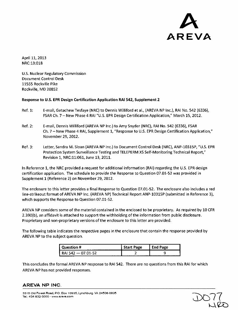
A AREVA April 11, 2013 NRC:13:018 U.S. Nuclear Regulatory Commission Document Control Desk 11555 Rockville Pike Rockville, MD 20852 Response to U.S. EPR Design Certification Application RAI 542, Supplement 2 Ref. 1: E-mail, Getachew Tesfaye (NRC) to Dennis Williford et al., (AREVA NP Inc.), RAI No. 542 (6336), FSAR Ch. 7 - New Phase 4 RAI "U.S. EPR Design Certification Application," March 15, 2012. Ref. 2: E-mail, Dennis Williford (AREVA NP Inc.) to Amy Snyder (NRC), RAI No. 542 (6336), FSAR Ch. 7 - New Phase 4 RAI, Supplement 1, "Response to U.S. EPR Design Certification Application," November 29, 2012. Ref. 3: Letter, Sandra M. Sloan (AREVA NP Inc.) to Document Control Desk (NRC), ANP-10315P, "U.S. EPR Protection System Surveillance Testing and TELEPERM XS Self-Monitoring Technical Report," Revision 1, NRC:11:061, June 13, 2011. In Reference 1, the NRC provided a request for additional information (RAI) regarding the U.S. EPR design certification application. The schedule to provide the Response to Question 07.01-52 was provided in Supplement I (Reference 2) on November 29, 2012. The enclosure to this letter provides a final Response to Question 07.01-52. The enclosure also includes a red line-strikeout format of AREVA NP Inc. (AREVA NP) Technical Report ANP-10315P (submitted in Reference 3), which supports the Response to Question 07.01-52. AREVA NP considers some of the material contained in the enclosed to be proprietary. As required by 10 CFR 2.390(b), an affidavit is attached to support the withholding of the information from public disclosure. Proprietary and non-proprietary versions of the enclosure to this letter are provided. The following table indicates the respective pages in the enclosure that contain the response provided by AREVA NP to the subject question. Question # Start Page End Page RAI 542 - 07.01-52 2 9 This concludes the formal AREVA NP response to RAI 542. There are no questions from this RAI for which AREVA NP has not provided responses. AREVA NP INC. 3315 Old Forest Road, PO. Box 10935, Lynchburg, VA 24506-0935 T7 Tel.: 434 832-3000 - www.areva.comr "7Vx
Transcript of Response to U.S. EPR Design Certification Application RAI ... · U.S. EPR Design Certification...
AAREVA
April 11, 2013NRC:13:018
U.S. Nuclear Regulatory CommissionDocument Control Desk11555 Rockville PikeRockville, MD 20852
Response to U.S. EPR Design Certification Application RAI 542, Supplement 2
Ref. 1: E-mail, Getachew Tesfaye (NRC) to Dennis Williford et al., (AREVA NP Inc.), RAI No. 542 (6336),FSAR Ch. 7 - New Phase 4 RAI "U.S. EPR Design Certification Application," March 15, 2012.
Ref. 2: E-mail, Dennis Williford (AREVA NP Inc.) to Amy Snyder (NRC), RAI No. 542 (6336), FSARCh. 7 - New Phase 4 RAI, Supplement 1, "Response to U.S. EPR Design Certification Application,"November 29, 2012.
Ref. 3: Letter, Sandra M. Sloan (AREVA NP Inc.) to Document Control Desk (NRC), ANP-10315P, "U.S. EPRProtection System Surveillance Testing and TELEPERM XS Self-Monitoring Technical Report,"Revision 1, NRC:11:061, June 13, 2011.
In Reference 1, the NRC provided a request for additional information (RAI) regarding the U.S. EPR designcertification application. The schedule to provide the Response to Question 07.01-52 was provided inSupplement I (Reference 2) on November 29, 2012.
The enclosure to this letter provides a final Response to Question 07.01-52. The enclosure also includes a redline-strikeout format of AREVA NP Inc. (AREVA NP) Technical Report ANP-10315P (submitted in Reference 3),which supports the Response to Question 07.01-52.
AREVA NP considers some of the material contained in the enclosed to be proprietary. As required by 10 CFR2.390(b), an affidavit is attached to support the withholding of the information from public disclosure.Proprietary and non-proprietary versions of the enclosure to this letter are provided.
The following table indicates the respective pages in the enclosure that contain the response provided byAREVA NP to the subject question.
Question # Start Page End Page
RAI 542 - 07.01-52 2 9
This concludes the formal AREVA NP response to RAI 542. There are no questions from this RAI for which
AREVA NP has not provided responses.
AREVA NP INC.
3315 Old Forest Road, PO. Box 10935, Lynchburg, VA 24506-0935 T7Tel.: 434 832-3000 - www.areva.comr
"7VxZ7Y
Document Control DeskApril 11, 2013
NRC:13:018Page 2
If you have any questions related to this information, please contact Len Gucwa by telephone at
(434) 832-3466, or by e-mail at [email protected].
Regulatory AffairsAREVA NP Inc.
Enclosures:1. Proprietary Response to U.S. EPR Design Certification Application RAI 542, Supplement 2
2. Non-Proprietary Response to U.S. EPR Design Certification Application RAI 542, Supplement 2
3. Notarized Affidavit
cc: A. M. SnyderDocket 52-020
AFFIDAVIT
COMMONWEALTH OF VIRGINIA )) ss.
CITY OF LYNCHBURG )
1. My name is Gayle F. Elliott. I am Manager, Product Licensing, for AREVA
NP Inc. (AREVA NP) and as such I am authorized to execute this Affidavit.
2. I am familiar with the criteria applied by AREVA NP to determine whether
certain AREVA NP information is proprietary. I am familiar with the policies established by
AREVA NP to ensure the proper application of these criteria.
3. I am familiar with the AREVA NP information contained in the document titled
"Response to U.S. EPR Design Certification Application RAI 542, Supplement 2," and referred
to herein as "Document." Information contained in this Document has been classified by
AREVA NP as proprietary in accordance with the policies established by AREVA NP for the
control and protection of proprietary and confidential information.
4. This Document contains information of a proprietary and confidential nature
and is of the type customarily held in confidence by AREVA NP and not made available to the
public. Based on my experience, I am aware that other companies regard information of the
kind contained in this Document as proprietary and confidential.
5. This Document has been made available to the U.S. Nuclear Regulatory
Commission in confidence with the request that the information contained in this Document be
withheld from public disclosure. The request for withholding of proprietary information is made in
accordance with 10 CFR 2.390. The information for which withholding from disclosure is
requested qualifies under 10 CFR 2.390(a)(4) "Trade secrets and commercial or financial
information":
6. The following criteria are customarily applied by AREVA NP to determine
whether information should be classified as proprietary:
(a) The information reveals details of AREVA NP's research and development
plans and programs or their results.
(b) Use of the information by a competitor would permit the competitor to
significantly reduce its expenditures, in time or resources, to design, produce,
or market a similar product or service.
(c) The information includes test data or analytical techniques concerning a
process, methodology, or component, the application of which results in a
competitive advantage for AREVA NP.
(d) The information reveals certain distinguishing aspects of a process,
methodology, or component, the exclusive use of which provides a
competitive advantage for AREVA NP in product optimization or marketability.
(e) The information is vital to a competitive advantage held by AREVA NP, would
be helpful to competitors to AREVA NP, and would likely cause substantial
harm to the competitive position of AREVA NP.
The information in the Document is considered proprietary for the reasons set forth in
paragraphs 6(c) and 6(d) above.
7. In accordance with AREVA NP's policies governing the protection and control
of information, proprietary information contained in this Document has been made available, on
a limited basis, to others outside AREVA NP only as required and under suitable agreement
providing for nondisclosure and limited use of the information.
8. AREVA NP policy requires that proprietary information be kept in a secured
file or area and distributed on a need-to-know basis.
9. The foregoing statements are true and correct to the best of my knowledge,
information, and belief.
/-v v
SUBSCRIBED before me this __,___
day of 4 . 2013.
Sherry L. McFadenNOTARY PUBLIC, COMMONWEALTH OF VIRGINIAMY COMMISSION EXPIRES: 10/31/2014Reg. #7079129
q SHERRY L. MCFADENNotary Public
Commonwealth of Virginia7079129
My Commission Expires Oct 31, 2014
Response to
Request for Additional Information No. 542, Supplement 2
3/15/2012
U. S. EPR Standard Design CertificationAREVA NP Inc.
Docket No. 52-020SRP Section: 07.01 - Instrumentation and Controls - Introduction
Application Section: 07.01
QUESTIONS for Instrumentation, Controls and Electrical Engineering 1(AP1000/EPR Projects) (ICE1)
AREVA NP Inc.
Response to Request for Additional Information No. 542, Supplement 2U.S. EPR Design Certification Application Page 2 of 9
Question 07.01-52:
OPEN ITEM
New Phase 4 RAI
Provide a consolidated description and diagrams illustrating how the Teleperm XS (TXS)watchdog timer (WDT) would be able to execute the reactor trip function if the Actuation LogicUnit (ALU) processor locks-up. In addition, describe the dependency of the WDT on the ALUsoftware and hardware to perform its functions.
10 CFR 50.55a(h) incorporates by reference IEEE Std. 603-1991. Clause 5.5 of IEEE Std. 603-1991 requires that the safety systems shall be designed to accomplish their safety functionsunder the full range of applicable conditions enumerated in the design basis. Technical ReportANP-10315P, Section 2.2.6.2, addresses the function and operation of the WDT. As currentlywritten, Section 2.2.6.2 does not provide an adequate level of detail on the design function andoperation of the WDT. The applicant is requested to provide a detailed description for how theWDT would initiate a reactor trip, in a timely manner, if an ALU function processor experiencesa software or hardware-based failure that prevents the ALU function processor from performingits safety function. Specifically, the applicant is requested to provide answers to the followingitems.
a. Provide a detailed description within the final safety analysis report or within TechnicalReport ANP-10315P that clearly explains how the WDT will initiate a reactor trip signalwithin the Protection System and to verify this action in performed in a timely manner. Ifthe description is provided in Technical Report ANP-10315, provide a pointer in the finalsafety analysis report to the applicable sections in the report.
b. Provide a diagram that clearly demonstrates how the WDT interfaces with other TXSfunction processor components and its reliance upon other components to perform itsfunction.
c. Provide a logic diagram that demonstrates how the WDT's design configurationfacilitates a reactor trip on demand. Specifically, provide a more detailed description anda functional logic diagram that demonstrates how the WDT "hardwired signal" switch offthe power supplies of a function processor's I/O modules and how does this lead to areactor trip signal initiation.
d. Is the "hardwired signal" used to switch off the affected function processor's I/O powersupply the same signal used to initiate the Exception-Handler and are those signalsindependent of each other?
e. Describe the impact of an Run-Time Environment software failure on the WDT'soperations.
f. Describe how the WDT's operations are affected once the Exception-Handler is initiated.Specifically, when the applicant states that after a second "exceptional" situation occursafter a reset, which could take as long as five minutes or more, what functions or actionsis the WDT performing during the this time frame or during multiple resets of a functionprocessor?
g. Describe in greater detail the interaction between the Run-Time Environment softwarewith the various types of TXS system hardware components. In particular, describe in
AREVA NP Inc.
Response to Request for Additional Information No. 542, Supplement 2U.S. EPR Design Certification Application Page 3 of 9
greater detail what hardware components the Run-Time Environment interfaces with(WDTs, LEDs, EEPROMs, Hardware Organizational Tool, etc.) and the method for howthis interaction occurs, either directly or indirectly.
Response to Question 07.01-52:
a. The function of the watchdog timer (WDT) is to provide indication of the loss-of-cyclicoperation of the run time environment (RTE), which operates on the SVE2 centralprocessing unit (CPU). The WDT is implemented in separate hardware from the SVE2CPU.
At the beginning of the processing cycle of the RTE, the local cycle counter is incrementedand the watchdog timer is set to a value that is larger (by [ ] ) than theactivation cycle for the RTEs set in the TELEPERM XS Operating System Software. Thehardware WDT must be re-triggered by the RTE software before its expiration. If thesoftware fails to do so, the watchdog times out and a system interrupt signal is generated(called WDG).
When the WDT is activated (i.e., times out) it issues a non-maskable interrupt (NMI) thatmakes the microprocessor call the exception handler and stop cyclic operation. Theexception handler (a special interrupt service) saves the state of the SVE2 CPU (e.g.,
I I)for subsequent analysis and places the SVE2 CPU in a waiting loop (a defined fault state).Activation of the exception handler is indicated by front-plate light emitting diodes (LEDs) onthe SVE2 module.
J Eithermethod ensures the outputs from the subrack are placed in a safe state, which includesplacing the outputs in the trip position for channel reactor trip. This is application-specifichardware circuitry provided outside the TELEPERM XS subrack (see response to Item c formore details).
AREVA NP Inc.
Response to Request for Additional Information No. 542, Supplement 2U.S. EPR Design Certification Application Page 4 of 9
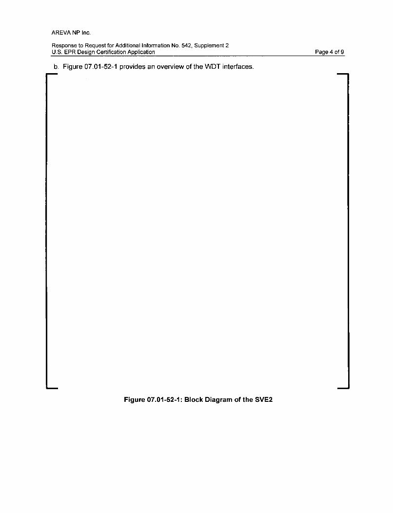
b. Figure 07.01-52-1 provides an overview of the WDT interfaces.
Figure 07.01-52-1: Block Diagram of the SVE2
AREVA NP Inc.
Response to Request for Additional Information No. 542, Supplement 2U.S. EPR Design Certification Application Page 5 of 9
AREVA NP Inc.
Response to Request for Additional Information No. 542, Supplement 2U.S. EPR Design Certification Application Page 6 of 9
Figure 07.01-52-2: Watchdog Timer Signals on SVE2 Front Panel
AREVA NP Inc.
Response to Request for Additional Information No. 542, Supplement 2U.S. EPR Design Certification Application Page 7 of 9
c. As described in the response to Item a, the BASP and WDG signals are used to interruptthe output power supply via a relay operated by the BASP/WDG signal.
The BASP and WDG signals from the front panel connector on the SVE2 module are usedto switch off the "ENABLE" signal of the I/O modules. Removing the "ENABLE" signal alsocuts the output power supply by using the module-internal electronic switch. This isapplication-specific hardware circuitry provided outside the TELEPERM XS subrack. Thisconcept is illustrated in the following figures below where the BASPIWDG signal is used toswitch off the output module power supply. Figure 07.01-52-3 is for single processor outputmodule. Figure 07.02-52-4 is for a master/checker configuration.
Figure 07.01-52-3: Single Processor Output Board Configuration
AREVA NP Inc.
Response to Request for Additional Information No. 542, Supplement 2U.S. EPR Design Certification Application Page 8 of 9
Figure 07.01-52-4: Master/Checker Configuration
d. The watchdog response is used as source for a NMI to the microprocessor of the SVE2 andit is also independently sent to the front connector for use in external circuit designs.
e. The SVE2 modules are equipped with a hardware watchdog. The monitoring time of thehardware watchdog is defined as the cycle time of the RTE plus I ] Thehardware watchdog is triggered by the cycle task at the beginning of each RTE cycle. If thesoftware fails to do so, the termination of regular cyclic operation is assumed. Thewatchdog is activated and indicates the failure by activating the hardwired WDG signal onfront connector X4.2 of the SVE2 module, which goes to "low".
The WDG hardware signal is used to signal a processor module failure. It is also used toswitch off I/O module power supplies to ensure a defined fail-safe behavior of the affectedTELEPERM XS computer, independently from software-based monitoring in the SVE2processing module.
Additionally, the exception-handler is activated by a hardware exception to initiate a reset ora shutdown of the SVE2. After activation, the exception-handler deactivates all outputboards through driver calls. Cyclic communication is stopped.
Switching off the output module power supply through the exception handler is a diversemeans to ensure fail-safe behavior of a TELEPERM XS computer. The main means forswitching off output power supply is by using the BASP/WDG signal as described in theresponse to Item b.
AREVA NP Inc.
Response to Request for Additional Information No. 542, Supplement 2U.S. EPR Design Certification Application Page 9 of 9
f. If the exception handler is activated by the RTE or a "real" exception the system reactiondepends on the elapsed time since the last reset. If the activation happens within aspecified period of [ ] cycles after a reset the SVE2 is shut down (e.g., with50 millisecond cycle time, the maximum period for exception to trigger shutdown is[ ]), otherwise a reset with automatic restart is performed.
While the exception handler is called/executed, the watchdog is not retriggered. During thistime the WDT is not re-triggered and the outputs are placed in a safe state until the reset iscomplete, as described in responses to Items a, b, and c. While the outputs are in safestate (LOW state), the LED "ERR" on the front panel of the SDO1 module is continuously litand can be verified by personnel. As soon as the reset is executed (at the end of theexception handler execution), the watchdog is triggered again by the SVE2 software.
g. The RTE interfaces directly with the SVE2 processor core and local memories. The systemsection and the bus interface section SVE2 hardware components are indirectly interfacedby the RTE through the processor core and local memories.
The system section comprises the I/O functions (with the exception of the TELEPERM XSbackplane bus/interface bus) and the monitoring functions of the SVE2. The I/O functions(i.e., ports, USART, interrupt controller, etc.) and the monitoring functions for multi-processoroperation are implemented in an ASIC (i.e., ESSC2). The local sequencer and the swapperare the interface between the system section and the processor. The WDT is a part of thesystem support controller ESSC2. The LEDs on the front plate of the SVE2 are interfacedby the RTE via the ESSC2.
The activation of the exception-handler is indicated by front-plate LEDs of the SVE2. Also,since the BASP signal is activated, exceptions are indirectly monitored by the cabinetmonitoring device.
The bus interface accesses the TELEPERM XS backplane bus. The bus interface is a dual-port random access memory between the system section (local) and the TELEPERM XSbackplane bus (global). For communication support several registers are implemented inthe bus interface section, which can be addressed locally and partly globally as well.
FSAR Impact:
The U.S. EPR FSAR will not be changed as a result of this question.
ANP-10315 Technical Report Impact:
Section 2.2 and new Figures 2.7, 2.8, 2.9, and 2.10 will be added to Technical ReportANP-10315.
U.S. EPR TM SurveillanceTesting and TELEPERM XSSelf-Monitoring
Technical Report
AN P-1 0315P
MARKUPS
AREVA NP Inc. ANP-10315PRevision 2
U.S. EPR Protctitn System Surveillance Testing and TELEPERM XS Self-Monitoring
Technical Report Pa-qe iv
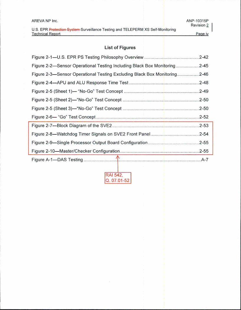
List of Figures
Figure 2-1 -U.S. EPR PS Testing Philosophy Overview ........................................... 2-42
Figure 2-2-Sensor Operational Testing Including Black Box Monitoring .................. 2-45
Figure 2-3-Sensor Operational Testing Excluding Black Box Monitoring ............ 2-46
Figure 2-4-APU and ALU Response Time Test ....................................................... 2-48
Figure 2-5 (Sheet 1)- "No-Go" Test Concept ........................................................... 2-49
Figure 2-5 (Sheet 2)-"No-Go" Test Concept ............................................................ 2-50
Figure 2-5 (Sheet 3)-"No-Go" Test Concept ............................................................ 2-50
Figure 2-6- "G o" Test C oncept ................................................................................ 2-52
Figure 2-7-Block Diagram of the SVE2 .......... ..................................... 2-53
Figure 2-8-Watchdog Timer Signals on SVE2 Front Panel ...................................... 2-54
Figure 2-9-Single Processor Output Board Configuration ........................................ 2-55
Figure 2-10-Master/Checker Configuration .............................................................. 2-55
Figure A -1- D A S Testing ......................... I ................................................................ A -7
RAI 542,Q. 07.01-52
AREVA NP Inc.
U.S. EPR Prtction System Surveillance Testing and TELEPERM XS Self-MonitoringTechnical ReDort
ANP-1 0315PRevision 2
Paae 2-23
system via the maintenance laptop.
The test machine only interfaces to the system under test throuah hard-wired interfaces
(24 VDC input and output); therefore, some of the software controls applicable to the
maintenance laptop (modifying changeable parameters, issue service request, etc.) are
not applicable to the test machine.
Controls for the test machine include the followina:
0 Storaqe in physically secure location when not in use.
* Physical access controls to prevent unauthorized individuals from obtaininc
access.
" Prohibit use for general purpose computing.
• User authorization process.
* Verify that adeauate precautions (e.a. patches up-to-date and on demand virus
scan) have been taken prior to connecting to the TELEPERM XS system.
* Verify work authorization prior to connectina to the TELEPERM XS system.
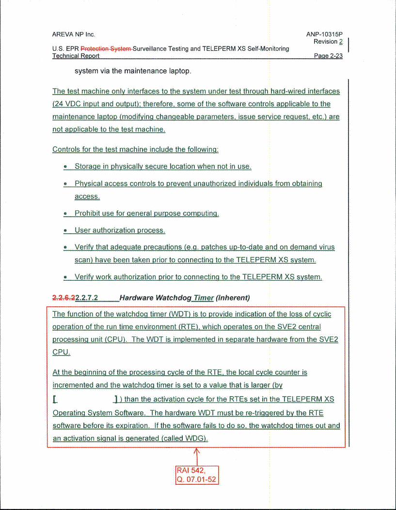
2..62-2.2.7.2 Hardware Watchdog Timer (Inherent)
The function of the watchdoq timer (WDT) is to provide indication of the loss of cyclic
operation of the run time environment (RTE), which operates on the SVE2 central
processing unit (CPU). The WDT is implemented in separate hardware from the SVE2
CPU.
At the beginning of the processing cycle of the RTE, the local cycle counter is
incremented and the watchdog timer is set to a value that is larger (by
L 1 ) than the activation cycle for the RTEs set in the TELEPERM XS
Operating System Software. The hardware WDT must be re-triggered by the RTE
software before its expiration. If the software fails to do so, the watchdog times out and
an activation signal is generated (called WDG).
RAI 542,Q. 07.01-52
AREVA NP Inc.
U.S. EPR Protoction System Surveillance Testing and TELEPERM XS Self-MonitoringTechnical Report
ANP-10315PRevision 2
Paae 2-24
The WDG hardware signal is used to signal a processor module failure. It is also used
to switch off I/O module power supplies to ensure a defined fail-safe behavior of the
affected TELEPERM XS computer, independently from software-based monitoring in
the SVE2 processinq module.
When the WDT is activated (i.e., times out) it issues a non-maskable interrupt that
makes the microprocessor call the exception handler (see Section 2.2.7.3) and stop
cyclic ooeration. The exceotion handler (a special interrunt servicel saves the state of
the SVE2 CPU (e.g., r
1 ) for subseauent analysis and places the SVE2 CPU in a
waitina loop (a defined fault state). Activation of the exceDtion handler is indicated bv
front-plate li-ght emitting diodes (LEDs) on the SVE2 module.
L
I This
is application-specific hardware circuitry provided outside the TXS subrack.
The diagram in Fiqure 2-7 provides an overview of the WDT interfaces.
L
I
TRAI 542,Q. 07.01-52
AREVA NP Inc.
U.S. EPR Protoctio,, Syctem Surveillance Testing and TELEPERM XS Self-MonitoringTechnical Report
ANP-1 0315PRevision 2
Paae 2-25
L
I
The WDG signal is also made available as a floating signal at the front connector of the
SVE2, independent from the microprocessor as shown in Figure 2-8.
gin I R I fg •l
x~ TUflcT!ofl nroce~or~ ~rn onuinnon wirn ~ n~rdwnm nn~eo waronoon timer I ne
FRORKOIIlly iRiu Wne wef 1PWat-GAuu is the rGYGcP 4IIFPi of the FURWIuRe eRVIFOR:Rnent 4- - i w
miliseond(mc). T-he h~ardwa~re watchdog timer musit be Fe triggered by the runtim
environment software before it6 expiration. If the soaftware fails to do so, an erri
assumed and a handwined signal i6 ued to indimate a pTroceso• r failure, and to switc• h off
the (i.puV, ,utput (,,) mo.dules' power u•pply to• . e.if. a defined fag! safe behavior of the
a- ................. ..... G...., -l--R.... . .... n t. . ite m. . - b.ase...... -. .- .. ..
Ssection 2.2.6.3).
Cx" - - -- _0 I H cm "S cx apH1.7 %3, roop"Hav ka
The BASP and WDG signals from the front panel connector on the SVE2 module are
used to switch off the "ENABLE" signal of the input/output (I/O) modules. Removing the
"ENABLE" signal also cuts the output power supply by using the module-internal
electronic switch. While the outputs are in safe state (LOW state), the LED "ERR" on
the front panel of the SDO1 module is continuously lit and can be verified by personnel.
This is application-specific hardware circuitry provided outside the TXS subrack. This
concept is illustrated in Figure 2-9 and Figure 2-10 where the BASP/WDG signal is used
to ensure switching off output module power supply.
RAI 542,Q. 07.01-52
AREVA NP Inc. ANP-1 0315P_________Revision2
U.S. EPR Protection System Surveillance Testing and TELEPERM XS Self-Monitoring i
Technical Report Paqe 2-26
Additionally, the exception-handler is activated by a hardware exception to initiate a
reset or a shutdown of the SVE2. After activation, the exception-handler deactivates all
output boards through driver calls. Cyclic communication is stopped.
Switching off the output module power supply through the exception handler is a diverse
means to ensure fail-safe behavior of a TELEPERM XS computer.
The hardware watchdog timer is periodically tested by the cyclic self-test. For this test,
a trip of the watchdog is triggered by the self-test task, and the trip is verified on the
associated interrupt signal. The "normal" response to this watchdog-interrupt is blocked
for the duration of the test. RAI 542,Q. 07.01-521
The activation of the WDT is locally indicated by the exception-handler front-plate LEDs
for the impacted SVE2 module and the Cabinet Monitoring Alarm, due to the BASP
signal being activated.
2.2.632.2.7.3 Exception-Handler (Inherent)
The exception-handler is activated when exceptional situations are encountered during
runtime (also in case of a fault detected by the cyclic self-test). After activation, the
exception-handler turns off the outputs through driver calls and stops cyclic
communication..........ate, all output boards through dF,, e calls (rF..id.s no oututs,
and .Y..i. communU.ication is sto p.ped. Self monitoring result information is saved, which
includes: exception type, exception number, exception address, memory dump and
stack dump.
Depending on the type of fault, the exception-handler either resets or halt6-the function
processor enters a defined fault state and all output signals are set to predetermined
safe states. See Technical Report ANP-10309P for information associated with failure
states.,0he .... BSG 'A'. . . .a defined fa,,t, •-• ate and all ,, a,,n,,t sginaalg Qa 9.•t G,
Werdete minedd saflesatt R- C Tei r-, n -- ;I DR e 9t AkI N P- 0-2- - D f Qr w Rf _rFa t 0 Q Ft
a..ociated. with fa.ilure states) the func•tion procesr,6 ars in..dicated. If a second
exceptional situation occurs within a specified period after a reset (depends on cycle
AREVA NP Inc.
U.S. EPR Prct9ioti.n System Surveillance Testing and TELEPERM XS Self-MonitoringTechnical Report
ANP-1 0315P
Revision 2 _
PaQe 2-37Technical Report
RAI 542,Q. 07.01-52
AREVA NP Inc.
U.S. EPR Surveillance Testing and TELEPERM XS Self-MonitoringTechnical Report
ANP-1 0315PRevision 2
Paqe 2-49
Figure 2-7-Block Diagram of the SVE2
I
AREVA NP Inc. ANP-10315PRevision 2
U.S. EPR Surveillance Testing and TELEPERM XS Self-MonitoringTechnical Report
Pane 2-50 I
•V
•
VVFigure 2-8-Watchdog Timer Signals on SVE2 Front Panel
AREVA NP Inc.
U.S. EPR Protoctien System Surveillance Testing and TELEPERM XS Self-MonitoringTh.rh n ir.,l Ra.nnrt
ANP-10315PRevision 2
Technical Re-rt Pane 2-56
Figure 2-9-Single Processor Output Board Configuration
AREVA NP Inc.
U.S. EPR Protection System Surveillance Testing and TELEPERM XS Self-MonitoringTechnical Report
ANP-1 0315PRevision 2
PaQe 3-57II I
Figure 2-10-Master/Checker Configuration
RAI 542, 1Q. 07.01-52 1
3.0 COMPLIANCE WITH REGULATORY REQUIREMENTS ANDCONFORMANCE TO GUIDANCE
This section addresses U.S. EPR compliance with regulatory requirements and
conformance to guidance relevant to testing provisions for the PS.
3.1 GDC 21 "Protection System Reliability and Testability" [1]
Requirement:
The PS shall be designed to permit periodic testing of its functioning when the reactor is
in operation, including a capability to test channels independently to determine failures
and losses of redundancy that may have occurred.
AREVA NP Inc. ANP-10315P
U.S. EPR Protocti9. System Surveillance Testing and TELEPERM XS Self-Monitoring i
Technical Report Page 4-1
4.0 REFERENCES
1. 10 CFR 50 Appendix A, "General Design Criteria."
2. Regulatory Guide 1.22, "Periodic Testing of Protection System Actuation Functions."
3. Regulatory Guide 1.47, "Bypassed and Inoperable Status Indication for NuclearPower Plant Safety Systems."
4. Regulatory Guide 1.118, Revision 3, "Periodic Testing of Electric Power andProtection Systems."
5. Regulatory Guide 1.171, "Software Unit Testing for Digital Computer Software Usedin Safety Systems of Nuclear Power Plants."
6. NUREG-0800, "Standard Review Plan", BTP 7-17, Revision 5.
7. IEEE Std 603-1998, "IEEE Standard Criteria for Safety Systems for Nuclear PowerGenerating Stations."
8. IEEE Std 338-1987, "IEEE Standard Criteria for the Periodic Surveillance Testing ofNuclear Power Generating Station Safety Systems."
9. IEEE Std 7-4.3.2-2003, "IEEE Standard Criteria for Digital Computers in SafetySystems of Nuclear Power Generating Stations."
10. EMF-2110(NP)(A), Revision 1, "TELEPERM XS: A Digital Reactor ProtectionSystem," July 2000.
11. ANP-10309P, Revision 2, "U.S. EPR Digital Protection System Technical Report,"May 2011.
12. Technical Report, "TXS Self-monitoringq and Fail-safe Behavior from Core-SoftwareRelease 3.6.2," PTLC-G/201 1/en/0059, Rev. A, 2012-01-20, AREVA NP Gmbh.
RAI 542,Q. 07.01-52