RESISTANCE OF A STEEL ROOF STIFFENING SYSTEM OF …
12
CZASOPISMO INŻYNIERII LĄDOWEJ, ŚRODOWISKA I ARCHITEKTURY JOURNAL OF CIVIL ENGINEERING, ENVIRONMENT AND ARCHITECTURE JCEEA, t. XXXVI, z. 66 (4/19), październik-grudzień 2019, s. 17-28, DOI:10.7862/rb.2019.20 Andrzej WOJNAR 1 Katarzyna SIEŃKOWSKA 2 Olena CHERNIEVA 3 RESISTANCE OF A STEEL ROOF STIFFENING SYSTEM OF INDUSTRIAL HALLS MADE FROM COLD FORMED PROFILES Single-nave halls with a steel structure are used in industrial construction and as storage, sports, public facilities, temporary buildings, etc. In terms of design, they consist of: main load-bearing systems, purlins and support systems for the wall casing and roofing. Individual elements of the hall structure can be made of hot- rolled profiles or cold formed, thin-walled elements with slender walls. The load capacity of the roof structure of an industrial hall, unconstrained by roofing, was analysed in the paper. The rigidity of the roof structure in its plane was ensured by an appropriate roof bracing system. It was also assumed that the work of the roof structure in a perpendicular direction to the roof plane is to be similar to the behavior of a steel grate - cooperation between purlins and rigid tie rods was assumed, with vertical loads applied only to the purlins. Keywords: metal structures, industrial hall, cold formed elements, stability of cold formed elements 1. Introduction Single-nave halls with a steel structure are often used in industrial construction and as storage, sports, public facilities, temporary buildings, etc. In terms of the structure, they consist of: main load-bearing systems (steel frames ensuring the stability of the structure in the plane of the frame), roof bracing and wall bracing (ensuring the stability of the structure in a plane 1 Corresponding author/autor do korespondencji: Andrzej Wojnar, Politechnika Rzeszowska, Katedra Konstrukcji Budowlanych, ul. Poznańska 2, 35-959 Rzeszów; tel. 178651615; [email protected]. http://orcid.org/0000-0002-0537-3864 2 Katarzyna Sieńkowska, Politechnika Rzeszowska, Katedra Konstrukcji Budowlanych, ul. Poznańska 2, 35-959 Rzeszów; [email protected]. https://orcid.org/0000-0003-1497-5821 3 Olena Chernieva, Department of Reinforced Concrete Structures and Transport Facilities, The Odesa State Academy of Civil Engineering and Architecture, Didrihsona 4, Odesa 65029, Ukraine, [email protected]
Transcript of RESISTANCE OF A STEEL ROOF STIFFENING SYSTEM OF …

CZASOPISMO INŻYNIERII LĄDOWEJ, ŚRODOWISKA I ARCHITEKTURY JOURNAL OF CIVIL ENGINEERING, ENVIRONMENT AND ARCHITECTURE
JCEEA, t. XXXVI, z. 66 (4/19), październik-grudzień 2019, s. 17-28, DOI:10.7862/rb.2019.20
Andrzej WOJNAR1
Katarzyna SIEŃKOWSKA2
Olena CHERNIEVA3
RESISTANCE OF A STEEL ROOF STIFFENING
SYSTEM OF INDUSTRIAL HALLS MADE FROM
COLD FORMED PROFILES
Single-nave halls with a steel structure are used in industrial construction and as
storage, sports, public facilities, temporary buildings, etc. In terms of design, they
consist of: main load-bearing systems, purlins and support systems for the wall
casing and roofing. Individual elements of the hall structure can be made of hot-
rolled profiles or cold formed, thin-walled elements with slender walls. The load
capacity of the roof structure of an industrial hall, unconstrained by roofing, was
analysed in the paper. The rigidity of the roof structure in its plane was ensured by
an appropriate roof bracing system. It was also assumed that the work of the roof
structure in a perpendicular direction to the roof plane is to be similar to the
behavior of a steel grate - cooperation between purlins and rigid tie rods was
assumed, with vertical loads applied only to the purlins.
Keywords: metal structures, industrial hall, cold formed elements, stability of cold
formed elements
1. Introduction
Single-nave halls with a steel structure are often used in industrial
construction and as storage, sports, public facilities, temporary buildings, etc.
In terms of the structure, they consist of: main load-bearing systems (steel
frames ensuring the stability of the structure in the plane of the frame), roof
bracing and wall bracing (ensuring the stability of the structure in a plane
1 Corresponding author/autor do korespondencji: Andrzej Wojnar, Politechnika Rzeszowska,
Katedra Konstrukcji Budowlanych, ul. Poznańska 2, 35-959 Rzeszów; tel. 178651615;
[email protected]. http://orcid.org/0000-0002-0537-3864 2 Katarzyna Sieńkowska, Politechnika Rzeszowska, Katedra Konstrukcji Budowlanych, ul. Poznańska 2,
35-959 Rzeszów; [email protected]. https://orcid.org/0000-0003-1497-5821 3 Olena Chernieva, Department of Reinforced Concrete Structures and Transport Facilities, The Odesa
State Academy of Civil Engineering and Architecture, Didrihsona 4, Odesa 65029, Ukraine,
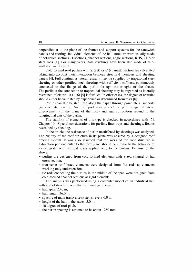
18 A. Wojnar, K. Sieńkowska, O. Chernieva
perpendicular to the plane of the frame) and support systems for the sandwich
panels and roofing. Individual elements of the hall structure were usually made
of hot-rolled sections - I-sections, channel sections, angle sections, RHS, CHS or
steel rods [1]. For many years, hall structures have been also made of thin-
walled elements [2, 3].
Cold formed roof purlins with Z (zet) or C (channel) section are calculated
taking into account their interaction between structural members and sheeting
panels [4]. Full continuous lateral restraint may be supplied by trapezoidal steel
sheeting or other profiled steel sheeting with sufficient stiffness, continuously
connected to the flange of the purlin through the troughs of the sheets.
The purlin at the connection to trapezoidal sheeting may be regarded as laterally
restrained, if clause 10.1.1(6) [5] is fulfilled. In other cases, the degree of restraint
should either be validated by experience or determined from tests [6].
Purlins can also be stabilized along their span through point lateral supports
(intermediate bracing). Such support may protect the purlins against lateral
displacement (in the plane of the roof) and against rotation around to the
longitudinal axis of the purlin.
The stability of elements of this type is checked in accordance with [5],
Chapter 10 - Special considerations for purlins, liner trays and sheetings. Beams
restrained by sheeting.
In the article, the resistance of purlin unstiffened by sheetings was analysed.
The rigidity of the roof structure in its plane was ensured by a designed roof
bracing system. It was also assumed that the work of the roof structure in
a direction perpendicular to the roof plane should be similar to the behavior of
a steel grate, with vertical loads applied only to the purlins. Because of the
above:
− purlins are designed from cold-formed elements with a zet, channel or hat
cross-section,
− transverse roof brace elements were designed from flat rods as elements
working only under tension,
− tie rods connecting the purlins in the middle of the span were designed from
cold-formed channel sections as rigid elements.
The analysis was performed using a computer model of an industrial hall
with a steel structure, with the following geometry:
− hall span: 20.0 m,
− hall length: 36.0 m,
− spacing of main transverse systems: every 6.0 m,
− height of the hall in the eaves: 5.0 m,
− 10 degree of roof pitch,
− the purlin spacing is assumed to be about 1250 mm.
Resistance of a Steel Roof Stiffening System of Industrial Halls Made from… 19
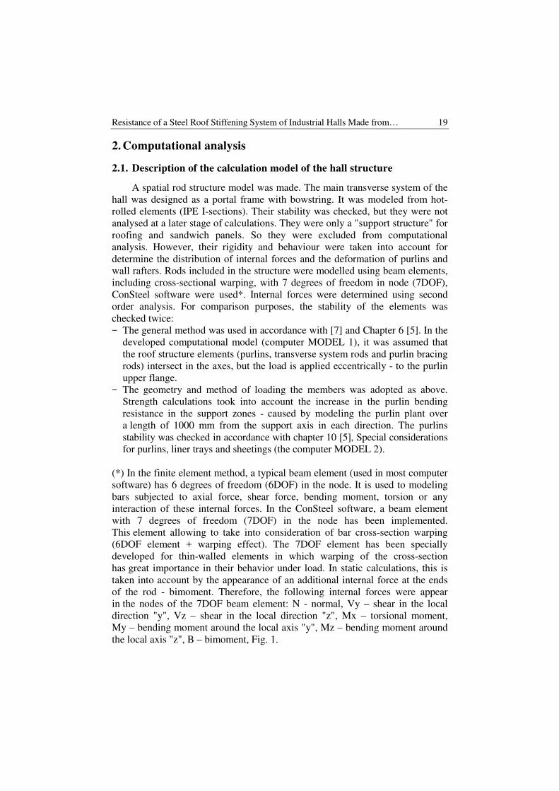
2. Computational analysis
2.1. Description of the calculation model of the hall structure
A spatial rod structure model was made. The main transverse system of the
hall was designed as a portal frame with bowstring. It was modeled from hot-
rolled elements (IPE I-sections). Their stability was checked, but they were not
analysed at a later stage of calculations. They were only a "support structure" for
roofing and sandwich panels. So they were excluded from computational
analysis. However, their rigidity and behaviour were taken into account for
determine the distribution of internal forces and the deformation of purlins and
wall rafters. Rods included in the structure were modelled using beam elements,
including cross-sectional warping, with 7 degrees of freedom in node (7DOF),
ConSteel software were used*. Internal forces were determined using second
order analysis. For comparison purposes, the stability of the elements was
checked twice:
− The general method was used in accordance with [7] and Chapter 6 [5]. In the
developed computational model (computer MODEL 1), it was assumed that
the roof structure elements (purlins, transverse system rods and purlin bracing
rods) intersect in the axes, but the load is applied eccentrically - to the purlin
upper flange.
− The geometry and method of loading the members was adopted as above.
Strength calculations took into account the increase in the purlin bending
resistance in the support zones - caused by modeling the purlin plant over
a length of 1000 mm from the support axis in each direction. The purlins
stability was checked in accordance with chapter 10 [5], Special considerations
for purlins, liner trays and sheetings (the computer MODEL 2).
(*) In the finite element method, a typical beam element (used in most computer
software) has 6 degrees of freedom (6DOF) in the node. It is used to modeling
bars subjected to axial force, shear force, bending moment, torsion or any
interaction of these internal forces. In the ConSteel software, a beam element
with 7 degrees of freedom (7DOF) in the node has been implemented.
This element allowing to take into consideration of bar cross-section warping
(6DOF element + warping effect). The 7DOF element has been specially
developed for thin-walled elements in which warping of the cross-section
has great importance in their behavior under load. In static calculations, this is
taken into account by the appearance of an additional internal force at the ends
of the rod - bimoment. Therefore, the following internal forces were appear
in the nodes of the 7DOF beam element: N - normal, Vy – shear in the local
direction "y", Vz – shear in the local direction "z", Mx – torsional moment,
My – bending moment around the local axis "y", Mz – bending moment around
the local axis "z", B – bimoment, Fig. 1.

20 A. Wojnar, K. Sieńkowska, O. Chernieva
a) b)
Fig. 1. a) six degrees of freedom at the node (6 DOF) – displacements (Ux, Uy, Uz) and rotations
(Φx, Φy, Φz) according to the local coordinate system of the element, b) seventh degree
of freedom at the node ( 7DOF) – section warp (Φ'x)
2.2. Assumptions used to calculate the roof structure
1. It was assumed that roof structure elements are not connected to a rigid roof
sheets - there is no continuous side brace. In the middle of the span, purlins
are supported by a roof purlin brace (by tie rods of purlin) that will support
them in the plane of the roof.
2. It was assumed that the tie rods of purlin are rigid enough to protect the purlin
against lateral displacement in the plane of the roof slope and against rotation.
3. It was assumed that the connection of tie rods of purlin and purlins is
sufficiently rigid in a plane perpendicular to the roof plane to enable rotation
protection of the purlin section (as assumption of the of taken KOBEX
structural system).
2.3. Description of roof structure elements
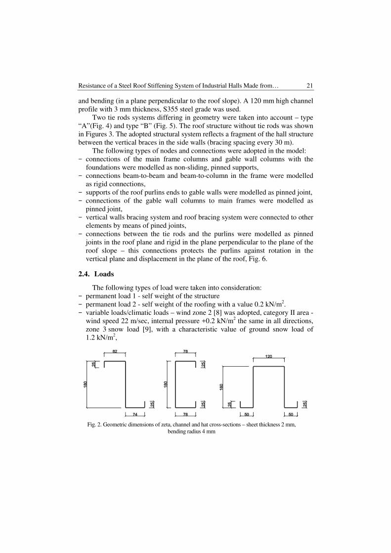
Purlins were designed and modeled as cold formed elements with zet,
channel and hat cross-sections, with 2 mm thickness and S355 steel grade.
The purlin height was assumed to be 180 mm in the case of Z-profiles and
C-profiles and 160 mm in the case of hat cross-sections. The cross-sectional
shape was adopted in accordance with the guidelines provided by the KOBEX
company, Fig. 2.
The transverse roof truss system was designed and modelled as tensile only
elements. A flat rod of 3x120 mm, made of S355 steel grade (placed vertically)
was adopted. The bracing bars were connected at the nodes with the web of each
purlin.
The tie rods connecting the purlins in the plane of the roof slope was used
in the case of roofs where the purlins are made from Z and C sections. The tie
rods were designed and modeled as elements subjected to tension, compression
Resistance of a Steel Roof Stiffening System of Industrial Halls Made from… 21
and bending (in a plane perpendicular to the roof slope). A 120 mm high channel
profile with 3 mm thickness, S355 steel grade was used.
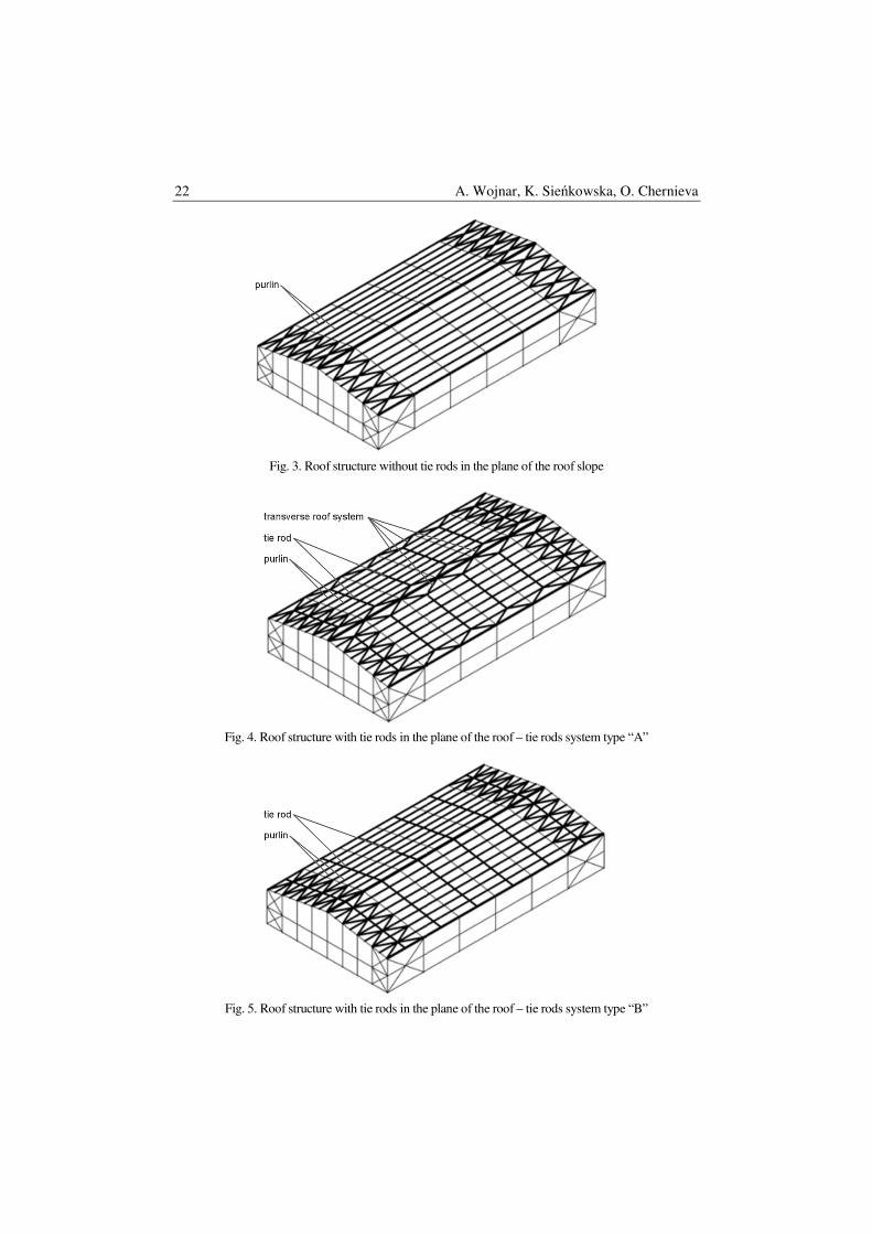
Two tie rods systems differing in geometry were taken into account – type
“A”(Fig. 4) and type “B” (Fig. 5). The roof structure without tie rods was shown
in Figures 3. The adopted structural system reflects a fragment of the hall structure
between the vertical braces in the side walls (bracing spacing every 30 m).
The following types of nodes and connections were adopted in the model:
− connections of the main frame columns and gable wall columns with the
foundations were modelled as non-sliding, pinned supports,
− connections beam-to-beam and beam-to-column in the frame were modelled
as rigid connections,
− supports of the roof purlins ends to gable walls were modelled as pinned joint,
− connections of the gable wall columns to main frames were modelled as
pinned joint,
− vertical walls bracing system and roof bracing system were connected to other
elements by means of pined joints,
− connections between the tie rods and the purlins were modelled as pinned
joints in the roof plane and rigid in the plane perpendicular to the plane of the
roof slope – this connections protects the purlins against rotation in the
vertical plane and displacement in the plane of the roof, Fig. 6.
2.4. Loads
The following types of load were taken into consideration:
− permanent load 1 - self weight of the structure
− permanent load 2 - self weight of the roofing with a value 0.2 kN/m2.
− variable loads/climatic loads – wind zone 2 [8] was adopted, category II area -
wind speed 22 m/sec, internal pressure +0.2 kN/m2 the same in all directions,
zone 3 snow load [9], with a characteristic value of ground snow load of
1.2 kN/m2,
Fig. 2. Geometric dimensions of zeta, channel and hat cross-sections – sheet thickness 2 mm,
bending radius 4 mm
22 A. Wojnar, K. Sieńkowska, O. Chernieva
Fig. 3. Roof structure without tie rods in the plane of the roof slope
Fig. 4. Roof structure with tie rods in the plane of the roof – tie rods system type “A”
Fig. 5. Roof structure with tie rods in the plane of the roof – tie rods system type “B”

Resistance of a Steel Roof Stiffening System of Industrial Halls Made from… 23
Fig. 6. View of the connection between C and Z purlins and tie rod
2.5. Calculation results
The calculation results were presented in the form of rod charts in Figs. 6
and 7. They represent the percentage of purlin effort. Three ranges expressed
in colours were adopted:
− light grey - resistance preserved, resistance <100%,
− dark grey - resistance exceeded 102% ≤ resistance.
The possibility of exceeding the load capacity of the element was accepted
but not more than 2%.
Calculation MODEL 1 – (axially connected elements, eccentrically applied
load). The stability of the elements was checked using the general method in
accordance with [7] and Chapter 6 of [5]. Resistance of roof structure elements
were shown in Fig. 7.
Conclusions – related to the MODEL 1:
− In the case of a roof structure in which the purlins are not stabilized by the
purlin ties, the zeta and channel section elements do not meet the ultimate limit
state conditions - the computational model is not stable (MODEL 1 C180x2-0
and MODEL 1 Z180x2-0, Fig. 7).
− In the case of a roof structure in which purlins are not stabilized by the tie
rods from channel profiles - elements with a hat cross-section and static
schema of a multi-span simply supported beam, do not meet the resistance
condition. Their resistance is around 104%. (MODEL 1 K160x2-0, Fig. 7).
− In the case of a roof structure in which purlins are not stabilized by the tie
rods from channel profiles - elements with a hat cross-section and static schema
24 A. Wojnar, K. Sieńkowska, O. Chernieva
a)
b)
c)
d)
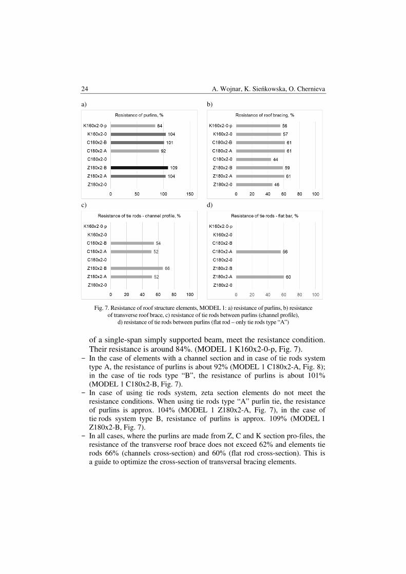
Fig. 7. Resistance of roof structure elements, MODEL 1: a) resistance of purlins, b) resistance
of transverse roof brace, c) resistance of tie rods between purlins (channel profile),
d) resistance of tie rods between purlins (flat rod – only tie rods type “A”)
of a single-span simply supported beam, meet the resistance condition.
Their resistance is around 84%. (MODEL 1 K160x2-0-p, Fig. 7). − In the case of elements with a channel section and in case of tie rods system
type A, the resistance of purlins is about 92% (MODEL 1 C180x2-A, Fig. 8);
in the case of tie rods type “B”, the resistance of purlins is about 101%
(MODEL 1 C180x2-B, Fig. 7).
− In case of using tie rods system, zeta section elements do not meet the
resistance conditions. When using tie rods type “A” purlin tie, the resistance
of purlins is approx. 104% (MODEL 1 Z180x2-A, Fig. 7), in the case of
tie rods system type B, resistance of purlins is approx. 109% (MODEL 1
Z180x2-B, Fig. 7).
− In all cases, where the purlins are made from Z, C and K section pro-files, the
resistance of the transverse roof brace does not exceed 62% and elements tie
rods 66% (channels cross-section) and 60% (flat rod cross-section). This is
a guide to optimize the cross-section of transversal bracing elements.
Resistance of a Steel Roof Stiffening System of Industrial Halls Made from… 25
Calculation MODEL 2 – (axially connected elements, eccentrically applied
load). The stability of the elements was checked in accordance with [5], Chapter
10 - Special considerations for purlins, liner trays and sheetings. The influence
of the purlins overlap on their resistance was taken into account by introducing
a function in the calculation model that allows mapping the purlin overlap in the
support zone. The range of the support zone was assumed to be 1000 mm,
obtained from the axis of the support. Resistance of roof structure elements were
shown in Fig. 8.
a)
b)
c)
d)
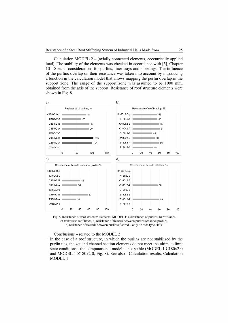
Fig. 8. Resistance of roof structure elements, MODEL 1: a) resistance of purlins, b) resistance
of transverse roof brace, c) resistance of tie rods between purlins (channel profile),
d) resistance of tie rods between purlins (flat rod – only tie rods type “B”).
Conclusions – related to the MODEL 2
− In the case of a roof structure, in which the purlins are not stabilized by the
purlin ties, the zet and channel section elements do not meet the ultimate limit
state conditions - the computational model is not stable (MODEL 1 C180x2-0
and MODEL 1 Z180x2-0, Fig. 8). See also - Calculation results, Calculation
MODEL 1
26 A. Wojnar, K. Sieńkowska, O. Chernieva
− In the case of a roof structure, in which purlins are not stabilized by the tie
rods from channel profiles, - elements with a hat cross-section and static
schema of a single-span simply supported beam meet the resistance condition.
Their resistance is around 81% (MODEL 1 K160x2-0-p, Fig. 6). In case
multi-span simply supported beam their resistance is around 65% (MODEL 1
K160x2-0, Fig. 8).
− In the case of elements with a channel section and in case of tie rods system
type A The resistance of purlins is about 90% (MODEL 2 C180x2-A, Fig. 7);
in the case of tie rods type “B”, the resistance of purlins is about 92%
(MODEL 1 C180x2-B, Fig. 8).
− In case of using tie rods system zet section elements do not meet the
resistance conditions. When using tie rods type “A” type purlin tie, the
resistance of purlins is approx. 101% (MODEL 1 Z180x2-A, Fig. 7), in the
case of tie rods type B resistance of purlins is approx. 105% (MODEL 1
Z180x2-B, Fig. 8).
− In all cases, where the purlins are made from Z, C and K section profiles, the
resistance of the transverse roof brace does not exceed 44% and elements tie
rods 61% (channels cross-section) and 60% (flat rod cross-section). This is
a guide how to optimize the cross-section of transversal bracing elements.
2.6. General conclusions and recommendations
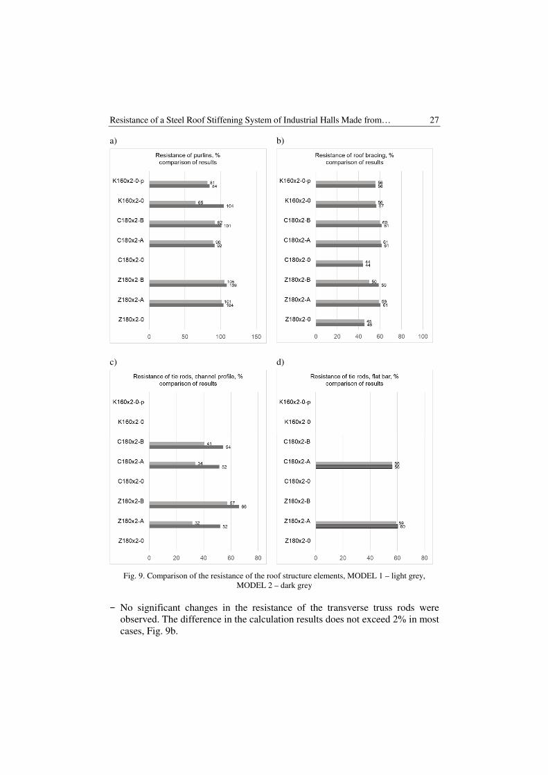
The results of calculations carried out using MODEL 1 and MODEL 2 were
compared with each other in Fig. 9. Compared: resistance of purlins (Fig. 9a),
resistance of transverse brace system (Fig. 9b), resistance of tie rods - channel
profile (Fig. 9c), resistance of tie rods - flat profile (Fig. 9d).
General conclusions and recommendations are as follows:
− The calculations carried out indicate that the use of a purlin with a hat cross-
section and a static scheme of a single-span simply supported beam is
an effective solution and does not require the use of tie rods system in the
plane of the roof slope.
− In the case of zeta and channel purlins, the use of a tie rods system increases
their resistance by introducing an additional node support stabilizing the
cross-section of the purlins in the middle of its span. The calculation model is
stable. The results obtained oscillate in the range of approx. 90-110% of the
resistance of the element. In this case, purlins are elements with a static
schema of a continuous beam simply-supported in a plane perpendicular to
the plane of the roof and additionally supported by the tie rods with channel
cross-section in the span - in the plane of the roof.
− The resistance of the purlins carried out in accordance with [5], Chapter 10
gives slightly lower results than the resistance calculated using the general
method according to [5], Chapter 6. The difference in this case does not
exceed 10%, except for the purlins hat section, Fig. 9a.
Resistance of a Steel Roof Stiffening System of Industrial Halls Made from… 27
a)
b)
c)
d)
Fig. 9. Comparison of the resistance of the roof structure elements, MODEL 1 – light grey,
MODEL 2 – dark grey
− No significant changes in the resistance of the transverse truss rods were
observed. The difference in the calculation results does not exceed 2% in most
cases, Fig. 9b.
28 A. Wojnar, K. Sieńkowska, O. Chernieva
− No significant changes in resistance of tie rods type “A” (flat rods subject
only to tension) were observed, Fig. 9d.
− Comparing the results of calculations from both models, significant
differences were observed in the resistance of the tie rods type “A “- channel
elements being the element stiffening the purlins, Fig. 9c. This issue requires
further analysis.
Artykuł został opracowany w ramach realizacji projektu badawczego realizowanego
we współpracy Politechniki Rzeszowskiej i firmy FPUH KOBEX, w ramach działania:
Regionalny Program Operacyjny Województwa Podkarpackiego na lata 2014–2020,
Oś priorytetowa: I Konkurencyjna i innowacyjna gospodarka, Działanie: 1.2 Badania
przemysłowe, prace rozwojowe oraz ich wdrożenia, Typ projektu: Prace B+R.
References
[1] Górski M., Kozłowski A., Kubiszyn W., Leń D., Pisarek Z., Szczerba R., Ślęczka L.:
Konstrukcje stalowe. Przykłady obliczeń według PN-EN 1993-1. Część trzecia. Hale
i wiaty, Oficyna Wydawnicza Politechniki Rzeszowskiej, Rzeszów 2015.
[2] Kurzawa Z., Rzeszut K., Szumigała M.: Stalowe konstrukcje prętowe. Część III
Konstrukcje z łukami, elementy cienkościenne, pokrycia membranowe, elementy
zespolone, belki podsuwnicowe, Wydawnictwo Politechniki Poznańskiej.
[3] Piekarczyk M.T.: Selected Design Problems of Thin-walled Steel Members and
Connections in Building Structures, Cracow University of Technology, Cracow 2018.
[4] Goczek J.: Belki z kształtowników giętych stężone poszyciem z blach fałdowych,
Monografie Politechnika Łódzka, 2013.
[5] EN 1993-1-3 (2006): Eurocode 3: Design of steel structures – Part 1-3: General rules
– Supplementary rules for cold-formed members and sheeting. European Committee
for Standardization, Brussels.
[6] Giżejowski M.: Sheat-to-purlin Fasteners Arragement and the Value of Rota-tional
Resistant of Cold-formed Z-purlins. Journal of Constucional Steel Research 151,
185-193, 2018.
[7] EN 1993-1-1 (2005): Eurocode 3: Design of steel structures – Part 1-1: General rules
for buildings. European Committee for Standardization, Brussels.
[8] PN-EN 1991-1-4 Eurocode 1: Actions on structures, Part 1-4: General ac-tions –
Wind actions.
[9] PN-EN 1991-1-3 Eurocode: Actions on structures, Part 1-3: General actions – Snow
loads.
Przesłano do redakcji: 10.01.2020 r.