Residential Power Direct Vent Gas 184333-003 1105
36
Instruction Manual for Residential Power Direct Vent Gas Water Heaters ALL TECHNICAL AND WARRANTY QUESTIONS: SHOULD BE DIRECTED TO THE LOCAL DEALER FROM WHOM THE WATER HEATER WAS PURCHASED. IF YOU ARE UNSUCCESSFUL, PLEASE WRITE TO THE COMPANY LISTED ON THE RATING PLATE ON THE WATER HEATER. –Do not store or use gasoline or other flammable vapors and liquids in the vicinity of this or any other appliance. –WHAT TO DO IF YOU SMELL GAS • Do not try to light any appliance. • Do not touch any electrical switch; do not use any phone in your building. • Immediately call your gas supplier from a neighbor's phone. Follow the gas supplier's instructions. • If you cannot reach your gas supplier, call the fire department. –Installation and service must be performed by a qualified installer, service agency or the gas supplier. WARNING: If the information in these instructions are not followed exactly, a fire or explosion may result, causing property damage, personal injury or death. Improper installation, adjustment, alter- ation, service or maintenance can cause DEATH, SERIOUS BODILY INJURY, OR PROPERTY DAMAGE. Refer to this manual for assistance or consult the local gas utility for further information. Flammable vapors may be drawn by air cur- rents from other areas of the structure to this appliance. WARNING WARNING READ THE GENERAL SAFETY SECTION BEGINNING ON INSIDE COVER AND THEN THIS ENTIRE MANUAL BEFORE INSTALLING OR OPERATING THIS WATER HEATER. Save this Manual for Future Reference. For Your Safety AN ODORANT IS ADDED TO THE GAS USED BY THIS WATER HEATER 184333-003 11-05 GAMA certification applies to all residential gas water heaters with capacities of 20 to 100 gallons with input rating of 75,000 BTU/Hr. or less. NOT FOR USE IN MANUFACTURED (MOBILE) HOMES WARNING
Transcript of Residential Power Direct Vent Gas 184333-003 1105

Instruction Manual forResidential Power Direct Vent Gas Water Heaters
ALL TECHNICAL AND WARRANTY QUESTIONS: SHOULD BE DIRECTED TO THE LOCAL DEALER FROMWHOM THE WATER HEATER WAS PURCHASED. IF YOU ARE UNSUCCESSFUL, PLEASE WRITE TO THECOMPANY LISTED ON THE RATING PLATE ON THE WATER HEATER.
–Do not store or use gasoline or otherflammable vapors and liquids in the vicinityof this or any other appliance.
–WHAT TO DO IF YOU SMELL GAS• Do not try to light any appliance.• Do not touch any electrical switch; do not
use any phone in your building.• Immediately call your gas supplier from a
neighbor's phone. Follow the gas supplier'sinstructions.
• If you cannot reach your gas supplier, callthe fire department.
–Installation and service must be performedby a qualified installer, service agency or thegas supplier.
WARNING: If the information in theseinstructions are not followed exactly, a fireor explosion may result, causing propertydamage, personal injury or death.
Improper installation, adjustment, alter-ation, service or maintenance can causeDEATH, SERIOUS BODILY INJURY, ORPROPERTY DAMAGE. Refer to this manualfor assistance or consult the local gas utilityfor further information.
Flammable vapors may be drawn by air cur-rents from other areas of the structure to thisappliance.
WARNING
WARNING
READ THE GENERAL SAFETY SECTIONBEGINNING ON INSIDE COVER AND THENTHIS ENTIRE MANUAL BEFORE INSTALLINGOR OPERATING THIS WATER HEATER.
Save this Manual for Future Reference.
For Your Safety AN ODORANT IS ADDED TO THE GASUSED BY THIS WATER HEATER
184333-00311-05
GAMA certification applies to allresidential gas water heaters withcapacities of 20 to 100 gallonswith input rating of 75,000BTU/Hr. or less.
NOT FOR USE IN MANUFACTURED (MOBILE) HOMES
WARNING
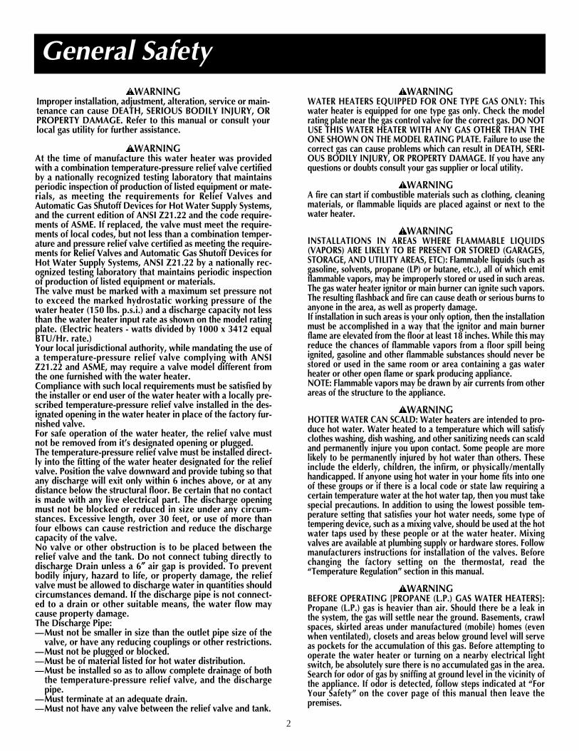
General Safety
2
WARNINGWATER HEATERS EQUIPPED FOR ONE TYPE GAS ONLY: Thiswater heater is equipped for one type gas only. Check the modelrating plate near the gas control valve for the correct gas. DO NOTUSE THIS WATER HEATER WITH ANY GAS OTHER THAN THEONE SHOWN ON THE MODEL RATING PLATE. Failure to use thecorrect gas can cause problems which can result in DEATH, SERI-OUS BODILY INJURY, OR PROPERTY DAMAGE. If you have anyquestions or doubts consult your gas supplier or local utility.
WARNINGA fire can start if combustible materials such as clothing, cleaningmaterials, or flammable liquids are placed against or next to thewater heater.
WARNINGINSTALLATIONS IN AREAS WHERE FLAMMABLE LIQUIDS(VAPORS) ARE LIKELY TO BE PRESENT OR STORED (GARAGES,STORAGE, AND UTILITY AREAS, ETC): Flammable liquids (such asgasoline, solvents, propane (LP) or butane, etc.), all of which emitflammable vapors, may be improperly stored or used in such areas.The gas water heater ignitor or main burner can ignite such vapors.The resulting flashback and fire can cause death or serious burns toanyone in the area, as well as property damage.If installation in such areas is your only option, then the installationmust be accomplished in a way that the ignitor and main burnerflame are elevated from the floor at least 18 inches. While this mayreduce the chances of flammable vapors from a floor spill beingignited, gasoline and other flammable substances should never bestored or used in the same room or area containing a gas waterheater or other open flame or spark producing appliance. NOTE: Flammable vapors may be drawn by air currents from otherareas of the structure to the appliance.
WARNINGHOTTER WATER CAN SCALD: Water heaters are intended to pro-duce hot water. Water heated to a temperature which will satisfyclothes washing, dish washing, and other sanitizing needs can scaldand permanently injure you upon contact. Some people are morelikely to be permanently injured by hot water than others. Theseinclude the elderly, children, the infirm, or physically/mentallyhandicapped. If anyone using hot water in your home fits into oneof these groups or if there is a local code or state law requiring acertain temperature water at the hot water tap, then you must takespecial precautions. In addition to using the lowest possible tem-perature setting that satisfies your hot water needs, some type oftempering device, such as a mixing valve, should be used at the hotwater taps used by these people or at the water heater. Mixingvalves are available at plumbing supply or hardware stores. Followmanufacturers instructions for installation of the valves. Beforechanging the factory setting on the thermostat, read the“Temperature Regulation” section in this manual.
WARNINGBEFORE OPERATING [PROPANE (L.P.) GAS WATER HEATERS]:Propane (L.P.) gas is heavier than air. Should there be a leak inthe system, the gas will settle near the ground. Basements, crawlspaces, skirted areas under manufactured (mobile) homes (evenwhen ventilated), closets and areas below ground level will serveas pockets for the accumulation of this gas. Before attempting tooperate the water heater or turning on a nearby electrical lightswitch, be absolutely sure there is no accumulated gas in the area.Search for odor of gas by sniffing at ground level in the vicinity ofthe appliance. If odor is detected, follow steps indicated at “ForYour Safety” on the cover page of this manual then leave thepremises.
WARNINGImproper installation, adjustment, alteration, service or main-tenance can cause DEATH, SERIOUS BODILY INJURY, ORPROPERTY DAMAGE. Refer to this manual or consult yourlocal gas utility for further assistance.
WARNINGAt the time of manufacture this water heater was providedwith a combination temperature-pressure relief valve certifiedby a nationally recognized testing laboratory that maintainsperiodic inspection of production of listed equipment or mate-rials, as meeting the requirements for Relief Valves andAutomatic Gas Shutoff Devices for Hot Water Supply Systems,and the current edition of ANSI Z21.22 and the code require-ments of ASME. If replaced, the valve must meet the require-ments of local codes, but not less than a combination temper-ature and pressure relief valve certified as meeting the require-ments for Relief Valves and Automatic Gas Shutoff Devices forHot Water Supply Systems, ANSI Z21.22 by a nationally rec-ognized testing laboratory that maintains periodic inspectionof production of listed equipment or materials.The valve must be marked with a maximum set pressure notto exceed the marked hydrostatic working pressure of thewater heater (150 lbs. p.s.i.) and a discharge capacity not lessthan the water heater input rate as shown on the model ratingplate. (Electric heaters - watts divided by 1000 x 3412 equalBTU/Hr. rate.)Your local jurisdictional authority, while mandating the use ofa temperature-pressure relief valve complying with ANSIZ21.22 and ASME, may require a valve model different fromthe one furnished with the water heater.Compliance with such local requirements must be satisfied bythe installer or end user of the water heater with a locally pre-scribed temperature-pressure relief valve installed in the des-ignated opening in the water heater in place of the factory fur-nished valve.For safe operation of the water heater, the relief valve mustnot be removed from it’s designated opening or plugged.The temperature-pressure relief valve must be installed direct-ly into the fitting of the water heater designated for the reliefvalve. Position the valve downward and provide tubing so thatany discharge will exit only within 6 inches above, or at anydistance below the structural floor. Be certain that no contactis made with any live electrical part. The discharge openingmust not be blocked or reduced in size under any circum-stances. Excessive length, over 30 feet, or use of more thanfour elbows can cause restriction and reduce the dischargecapacity of the valve.No valve or other obstruction is to be placed between therelief valve and the tank. Do not connect tubing directly todischarge Drain unless a 6″″ air gap is provided. To preventbodily injury, hazard to life, or property damage, the reliefvalve must be allowed to discharge water in quantities shouldcircumstances demand. If the discharge pipe is not connect-ed to a drain or other suitable means, the water flow maycause property damage.The Discharge Pipe:—Must not be smaller in size than the outlet pipe size of the
valve, or have any reducing couplings or other restrictions.—Must not be plugged or blocked.—Must be of material listed for hot water distribution.—Must be installed so as to allow complete drainage of both
the temperature-pressure relief valve, and the dischargepipe.
—Must terminate at an adequate drain.—Must not have any valve between the relief valve and tank.

General Safety (cont’d)
3
WARNINGThis water heater must not be installed directly on carpeting.Carpeting must be protected by a metal or wood panel beneaththe appliance extending beyond the full width and depth of theappliance by at least 3 inches (76.2mm) in any direction, or ifthe appliance is installed in an alcove or closet, the entire floormust be covered by the panel. Failure to heed this warning mayresult in a fire hazard.
WARNINGDo not install in a confined area such as a closet, unless you pro-vide ventilation air as shown in the “Locating The New WaterHeater” section. Never obstruct the flow of ventilation air. If youhave any doubts or questions at all, call your gas company. Fail-ure to provide ventilation air can result in a fire or explosion andcan cause DEATH, SERIOUS BODILY INJURY, OR PROPERTYDAMAGE.
WARNINGIf this water heater will be used in beauty shops, barber shops,cleaning establishments, or self-service laundries with dry clean-ing equipment, it is imperative that the water heater or waterheaters be installed so that combustion and ventilation air betaken from outside these areas. Refer to the “Locating The NewWater Heater” section of this manual and also the current editionof the National Fuel Gas Code, ANSI Z223.1, also referred to asNFPA 54 for specifics provided concerning air required.
WARNINGThe power direct vent water heater requires its own (separate)venting system. It cannot be connected to an existing vent pipeor chimney. It must be terminated to the outdoors. Failure toproperly install the venting system can result in asphyxiation, afire or explosion and can cause DEATH, SERIOUS BODILY IN-JURY, OR PROPERTY DAMAGE.
WARNINGNo vent damper installation is compatible with this power ventedwater heater design. No vent damper, whether it is operated ther-mally or otherwise is to be installed on this power vented waterheater. Alteration of any part of the factory-furnished vent assemblycould result in improper operation due to restriction of flue gases,spillage of flue gases and may cause carbon monoxide poisoning.
WARNING1. The appliance and its individual shutoff valve must be dis-
connected from the gas supply piping system during any pres-sure testing of the gas system at test pressures in excess of1/2 pound per square inch (3.5kPa).
2. The appliance must be isolated from the gas supply pipingsystem by closing its individual manual shutoff valve duringany pressure testing of the gas supply piping system at testpressures equal or less than 1/2 pound per square inch(3.5kPa).
WARNINGSoot build-up indicates a problem that requires correction be-fore further use. Turn “OFF” gas to water heater and leave “OFF”until repairs are made, because failure to correct the cause ofthe sooting can result in a fire or explosion causing DEATH, SE-RIOUS BODILY INJURY, OR PROPERTY DAMAGE.
WARNINGThe water heater must be properly vented outdoors. Never op-erate the water heater unless it is vented to the outdoors andhas adequate air supply to avoid risks of improper operation, ex-plosion or asphyxiation.
WARNINGVent termination must not be within 4 feet of any items such asgas meters, gas valves or other gas regulating equipment.
WARNINGObstructed or deteriorated vent systems may present a serioushealth risk or asphyxiation.
WARNINGChemical vapor corrosion of the flue and vent system may occurif air for combustion contains certain chemical vapors. Spray canpropellants, cleaning solvents, refrigerator and air conditionerrefrigerants, swimming pool chemicals, calcium and sodium chlo-ride, waxes, bleach, and process chemicals are typical compoundswhich are potentially corrosive.
WARNINGMinimum clearances between the water heater and combustibleand non-combustible construction are: 0 inches from sides, 0 inch-es from back, 6 inches from front of jacket to closet door and 12inches from top of jacket to combustible and non-combustiblematerial. Minimum vent clearance: 0 inches. Provide 24 inchesfront clearance for servicing and adequate clearance between thejacket top and ceiling for servicing the flue area.
WARNINGHYDROGEN GAS: Hydrogen gas can be produced in a hot watersystem that has not been used for a long period of time (generallytwo weeks or more). Hydrogen gas is extremely flammable andexplosive. To prevent the possibility of injury under these condi-tions, we recommend the hot water faucet be opened for severalminutes at the kitchen sink before any electrical appliances whichare connected to the hot water system are used (such as a dish-washer or washing machine). If hydrogen gas is present, there willprobably be an unusual sound similar to air escaping through thepipe as the hot water faucet is opened. There must be no smokingor open flame near the faucet at the time it is open.
WARNINGINSULATING JACKETS: When installing an external water heaterinsulation jacket on a gas water heater:a. DO NOT cover the temperature-pressure relief valve.b. DO NOT put insulation over any part of the top of the gas water
heater.c. DO NOT put insulation over the gas control valve or gas control
valve/burner cover, or any access areas to the burner.d. DO NOT let insulation around the gas water heater to get with-
in 8 inches of the floor (access for servicing the burner).e. DO NOT remove operating instructions, and safety related warn-
ing labels and materials affixed to the water heater. DO obtainnew warning and instruction labels from the manufacturer forplacement on the jacket directly over the existing labels.
Failure to heed this will result in the possibility of a fire or explosion.
WARNINGFlood damage to a water heater may not be readily visible or imme-diately detectible. However, over a period of time a flooded waterheater will create dangerous conditions which can cause DEATH,SERIOUS BODILY INJURY, OR PROPERTY DAMAGE. Call a qual-ified service technician or contractor to replace a flooded waterheater. Do not attempt to repair the unit! It must be replaced!
CAUTIONWATER HEATERS EVENTUALLY LEAK: Installation of the water heatermust be accomplished in such a manner that if the tank or any connec-tions should leak, the flow of water will not cause damage to the structure.For this reason, it is not advisable to install the water heater in an attic orupper floor. When such locations cannot be avoided, a suitable drain panshould be installed under the water heater. Drain pans are available atyour local hardware store. Such a drain pan must have a minimum lengthand width of at least 2 inches greater than the water heater dimensionsand must be piped to an adequate drain. Drain pan depth must allow foraccess to the outer doors for servicing the ignitor and burner.

General Safety ...............................................................................................................................2-3
Table of Contents.........................................................................................................................4
Introduction .........................................................................................................................................5
Preparing for the New Installation ..................................................................5
Typical Installation ....................................................................................................................6
Locating the New Water Heater ......................................................................7-9Facts to Consider About Location.......................................................................................................................7-8Combustion Air and Ventilation .........................................................................................................................8-9
Venting Clearances ..........................................................................................................................................8-9Air for Ventilation for Appliances Located in Confined Spaces ..............................................................................9
Installing the New Water Heater................................................................10-20Water Piping .......................................................................................................................................................10Temperature-Pressure Relief Valve ......................................................................................................................11Filling the Water Heater ......................................................................................................................................12Wiring............................................................................................................................................................12-13
Optional Field Installed Wiring ....................................................................................................................12-13Wiring Diagram.................................................................................................................................................13
Venting ..........................................................................................................................................................13-18Gas Piping .....................................................................................................................................................18-19Installation Checklist ...........................................................................................................................................20
Operating ..........................................................................................................................................21-23
Temperature Regulation .................................................................................................24
For Your Information .....................................................................................................25-26Start Up Conditions .............................................................................................................................................25
Condensation ....................................................................................................................................................25Smoke/Odor ......................................................................................................................................................25Thermal Expansion............................................................................................................................................25Strange Sounds..................................................................................................................................................25
Operational Conditions ..................................................................................................................................25-26Smelly Water.....................................................................................................................................................25"Air” In Hot Water Faucets ................................................................................................................................26Venting Manual Reset Switch ............................................................................................................................26High Temperature Limit Switch .........................................................................................................................26Not Enough or No Hot Water ............................................................................................................................26Water Is Too Hot ...............................................................................................................................................26
Periodic Maintenance ...................................................................................................27-29Venting System Inspection...................................................................................................................................27Burner Inspection ................................................................................................................................................27Burner Cleaning ..................................................................................................................................................27L.P. Gas Control Valve & Burner Assembly Replacement Information .................................................................28Housekeeping .....................................................................................................................................................28Anode Rod Inspection .........................................................................................................................................28Temperature-Pressure Relief Valve Operation......................................................................................................29Draining..............................................................................................................................................................29Drain Valve Washer Replacement .......................................................................................................................29Service ................................................................................................................................................................29
Leakage Checkpoints............................................................................................................30
Troubleshooting ......................................................................................................................31-33
Repair Parts ....................................................................................................................................34-37
Table of Contents
4

Abbreviations Found In This Instruction ManualCSA - Canadian Standards AssociationANSI - American National Standards InstituteNFPA - National Fire Protection Association
3. If after reading this manual you have any questions ordo not understand any portion of the instructions, callthe local gas utility or the manufacturer whose nameappears on the rating plate.
4. Carefully plan the place where you are going to put thewater heater. Correct combustion, vent action, andintake air and exhaust vent pipe installation are veryimportant in preventing death from possible carbonmonoxide poisoning and fires.Examine the location to ensure the water heater com-plies with the “Locating the New Water Heater” sectionin this manual.
5. For California installation this water heater must be braced,anchored, or strapped to avoid falling or moving duringan earthquake. See instructions for correct installation pro-cedures. Instructions may be obtained from your localdealer, wholesaler, public utilities or California Office ofthe State Architect, 400 P Street, Sacramento, CA 95814.
6. Massachusetts Code requires this water heater to beinstalled in accordance with Massachusetts 248-CMR2.00: State Plumbing Code and 248-CMR 5.00.
7. Complies with SCAQMD rule #1121 and districts havingequivalent NOx requirements.
Introduction
Thank You for purchasing this water heater. Wheninstalled according to State and Local Codes and main-tained according to the manufacturers instructions, it shouldgive you years of trouble free service.
1. Read the “General Safety” section, pages 2 and 3 of thismanual first and then the entire manual carefully. If youdon’t follow the safety rules, the water heater will notoperate properly. It could cause DEATH, SERIOUSBODILY INJURY AND/OR PROPERTY DAMAGE.This manual contains instructions for the installation,operation, and maintenance of the gas-fired waterheater. It also contains warnings through out the manu-al that you must read and be aware of. All warnings andall instructions are essential to the proper operation ofthe water heater and your safety. Since we cannot puteverything on the first few pages, READ THE ENTIREMANUAL BEFORE ATTEMPTING TO INSTALL OROPERATE THE WATER HEATER.
2. The installation must conform with the instructions in thismanual; gas company rules; and Local Codes, or in theabsence of Local Codes, with the current edition of theNational Fuel Gas code, ANSI Z223.1, also referred to asNFPA 54. This publication is available from your localgovernment or public library or gas company or by writ-ing NFPA, Batterymarch Park, Quincy, MA 02269.
Preparing for the New Installation
5
WARNINGThis gas-fired water heater is design certified by CSAInternational under American National Standard/CSAStandard for Gas Water Heaters, ANSI Z21.10.1 • CSA4.1 (current edition). The installation must conform withthis manual, Local Codes and with the current editionof the National Fuel Gas Code, ANSI Z223.1.This publication is available from your local governmentor public library, gas company, or by writing NFPA,Batterymarch Park, Quincy, MA 02269.
WARNINGToxic chemicals such as used for treatment of boilers ornon-potable water heating appliances shall never beintroduced into a potable water space heating system.
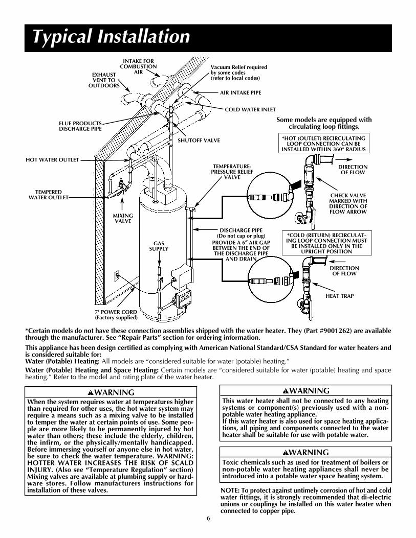
Typical Installation
6
COLD WATER INLET
HOT WATER OUTLET
TEMPEREDWATER OUTLET
EXHAUSTVENT TO
OUTDOORS
GASSUPPLY
TEMPERATURE-PRESSURE RELIEF
VALVE
MIXING VALVE
DISCHARGE PIPE (Do not cap or plug)
PROVIDE A 6″″ AIR GAPBETWEEN THE END OFTHE DISCHARGE PIPE
AND DRAIN
7' POWER CORD(Factory supplied)
INTAKE FORCOMBUSTION
AIR
FLUE PRODUCTSDISCHARGE PIPE
AIR INTAKE PIPE
Vacuum Relief requiredby some codes (refer to local codes)
SHUTOFF VALVE
NOTE: To protect against untimely corrosion of hot and coldwater fittings, it is strongly recommended that di-electricunions or couplings be installed on this water heater whenconnected to copper pipe.
*Certain models do not have these connection assemblies shipped with the water heater. They (Part #9001262) are availablethrough the manufacturer. See “Repair Parts” section for ordering information.
This appliance has been design certified as complying with American National Standard/CSA Standard for water heaters andis considered suitable for:Water (Potable) Heating: All models are “considered suitable for water (potable) heating.”Water (Potable) Heating and Space Heating: Certain models are “considered suitable for water (potable) heating and spaceheating.” Refer to the model and rating plate of the water heater.
WARNINGWhen the system requires water at temperatures higherthan required for other uses, the hot water system mayrequire a means such as a mixing valve to be installedto temper the water at certain points of use. Some peo-ple are more likely to be permanently injured by hotwater than others; these include the elderly, children,the infirm, or the physically/mentally handicapped.Before immersing yourself or anyone else in hot water,be sure to check the water temperature. WARNING:HOTTER WATER INCREASES THE RISK OF SCALDINJURY. (Also see “Temperature Regulation” section)Mixing valves are available at plumbing supply or hard-ware stores. Follow manufacturers instructions forinstallation of these valves.
*COLD (RETURN) RECIRCULAT-ING LOOP CONNECTION MUST
BE INSTALLED ONLY IN THEUPRIGHT POSITION
*HOT (OUTLET) RECIRCULATINGLOOP CONNECTION CAN BE
INSTALLED WITHIN 360° RADIUS
DIRECTIONOF FLOW
DIRECTIONOF FLOW
CHECK VALVEMARKED WITHDIRECTION OFFLOW ARROW
HEAT TRAP
Some models are equipped withcirculating loop fittings.
WARNINGThis water heater shall not be connected to any heatingsystems or component(s) previously used with a non-potable water heating appliance.If this water heater is also used for space heating applica-tions, all piping and components connected to the waterheater shall be suitable for use with potable water.

Facts to Consider About theLocationYou should carefully choose an indoor location for the new waterheater, because the placement is a very important considerationfor the safety of the occupants in the building and for the mosteconomical use of the appliance. This water heater is not for usein manufactured (mobile) homes or outdoor installation.Whether replacing an old water heater or installing the water heaterin a new location, the following critical points must be observed.1. The location selected should be indoors as close as practical to
the vent termination point, and as centralized with the water pip-ing system as possible. The water heater, as all water heaters, willeventually leak. Do not install without adequate drainage provi-sions where water flow will cause damage.
2. If vented through an outside wall or through the roof using 3″ ventpiping, the total vent run (vertical and horizontal) cannot exceeda total of 45 feet with one elbow. If more elbows are required,the venting distance must be reduced 5 feet for every 90° elbow.See page 15 for vent chart.
3. Vent piping cannot slope downward and horizontal runs require1/8″ per five foot rise. All horizontal runs require adequate supportat 31/2 foot intervals and vertical runs supported at 5 foot inter-vals.
4. The water heater requires its own (separate) venting system. Itcannot be connected to an existing vent pipe or chimney. It mustterminate to the outdoors. Whenever possible terminate the venton the leeward side of the building through an outside wall. Note:Condensation may be created, at times, as the combustion gasesexit the vent cap and discoloration of surfaces in proximity tothe vent cap may occur.
5. The water heater comes equipped with a 7 foot power cord whichcan be used to connect to a 110/120 volt power source if (1) localcodes allow, and (2) there is a three prong receptacle available.
7
Locating the New Water Heater 6. The location selection must provide adequate clearances
for servicing and proper operation of the water heater.
Figure 1
WARNINGThis water heater must not be installed directly on carpeting.Carpeting must be protected by a metal or wood panelbeneath the appliance extending beyond the full width anddepth of the appliance by at least 3 inches (76.2mm) in anydirection, or if the appliance is installed in an alcove or clos-et, the entire floor must be covered by the panel. Failure toheed this warning may result in a fire hazard.
WARNINGMinimum clearances between the water heater and combustibleand non-combustible construction are: 0 inches from sides, 0inches from back, 6 inches from front of jacket to closet doorand 12 inches from top of jacket to combustible and non-com-bustible material. Minimum vent clearance: 0 inches. Provide 24inches front clearance for servicing and adequate clearancebetween the jacket top and ceiling for servicing the flue area.
WARNINGPropellants of aerosol sprays and volatile compounds,(cleaners, chlorine based chemicals, refrigerants, etc.) inaddition to being highly flammable in many cases, will alsochange to corrosive hydrochloric acid when exposed to thecombustion products of the water heater. The results canbe hazardous, and also cause product failure.
WARNINGINSTALLATION IN AREAS WHERE FLAMMABLE LIQUIDS(VAPORS) ARE LIKELY TO BE PRESENT OR STORED(GARAGES, STORAGE AND UTILITY AREAS, ETC):Flammable liquids (such as gasoline, solvents, propane (LP)or butane, etc.) or other substances (such as adhesives, etc.),all of which emit flammable vapors, may be improperlystored or used in such areas. The gas water heater ignitoror main burner can ignite such vapors. The resulting flash-back and fire can cause death or serious burns to anyone inthe area, as well as property damage.If installation in such areas is your only option, then theinstallation must be accomplished in a way that the ignitorand main burner flame are elevated from the floor at least18 inches. While this may reduce the chances of flammablevapors from a floor spill being ignited, gasoline and otherflammable substances should never be stored or used in thesame room or area containing a gas water heater or otheropen flame or spark producing appliance.Also, the water heater must be located and/or protected soit is not subject to physical damage by a moving vehicle.NOTE: Flammable vapors may be drawn by air currentsfrom other areas of the structure to the appliance.
CAUTIONWATER HEATERS EVENTUALLY LEAK: Installation of the waterheater must be accomplished in such a manner that if the tank orany connections should leak, the flow of water will not causedamage to the structure. When such locations cannot be avoid-ed, a suitable drain pan should be installed under the waterheater. Drain pans are available at your local hardware store.Such a drain pan must have a minimum length and width of atleast 2 inches greater than the water heater dimensions and mustbe piped to an adequate drain. Drain pan depth must allow foraccess to the outer doors for servicing the ignitor and burner.
WARNINGDo not use an extension cord. If there is not a suitable recepta-cle with ground and/or local codes prohibit use of a power cord,field wiring must be provided.
WARNINGThe power direct vent water heater requires its own (separate)venting system. It cannot be connected to an existing vent pipeor chimney. It must be terminated to the outdoors. Failure toproperly install the venting system can result in asphyxiation, afire or explosion and can cause DEATH, SERIOUS BODILY IN-JURY, OR PROPERTY DAMAGE.

12″ min. FORCED AIRINLET
A
36″ min. IF “B” DIMENSIONIS LESS THAN 120″
A
PDVTERMINAL
PDVTERMINAL
A
GRADE
“B”
CORNER INSTALLATIONOF INLET AND OUTLETNOT RECOMMENDED
8
Locating the New Water Heater (cont’d)
Figure 2
Combustion Air and Exhaust
Venting Through an Outside Wall – Clearances
•0″ clearance for 3″ PVC, ABS, or CPVC Schedule 40 piping fromcombustible surfaces.
•18″ minimum in all directions from any obstruction, such as a wall,that may interfere.
•12″ minimum from the ground and corners, 9″ ceiling overhangs.Figure 2.
•The Power Direct Vent outlet terminal shall terminate at least 36″above any forced air inlet located within 10 feet. Figure 3.
•The Power Direct Vent outlet terminal of 50,000 BtuH input mod-els or less shall terminate at least 9″ below, 9″ horizontally from or9″ above any door, window or gravity air inlet into the building.Figure 3.
•The Power Direct Vent outlet terminal of over 50,000 BtuH inputmodels shall terminate at least 12″ below, 12″ horizontally from or12″ above any door, window or gravity air inlet into the building.Figure 3.
•18″ minimum from other natural draft (gravity) direct vent, powervent or power direct vent appliance inlet and/or outlet vent(s) whendirectly above or 135° to either side of center line. Figure 4, page 9.
•24″ minimum from any appliance inlet and/or outlet vents whendirectly below or 45° to either side of center line. Figure 4, page 9.
•The location selection must provide clearances for servicing andproper operation of the water heater. Figure 5.
•Vent termination must not be within 4 feet of any items such as gasmeters, gas valves or other gas regulating equipment.
Facts to Consider About theLocation (cont’d)
Figure 3
WARNINGFailure to have required clearances between water heaterand combustible material will result in a fire hazard.
WARNINGVent termination must not be within 4 feet of any items such asgas meters, gas valves or other gas regulating equipment.
WARNINGWhen determining the installation location for a power directvent water heater, snow accumulation and drifting should beconsidered in areas where applicable.
WARNINGIf this water heater will be used in beauty shops, barber shops,cleaning establishments, or self-service laundries with dry clean-ing equipment, it is imperative that the water heater or waterheaters be installed so that combustion and ventilation air betaken from outside these areas. Refer to the “Locating The NewWater Heater” section of this manual and also the current edi-tion of the National Fuel Gas Code, ANSI Z223.1, also referredto as NFPA 54 for specifics provided concerning air required.
WARNINGDo not install in a confined area such a closet, unless youprovide ventilation air as shown in the “Locating The NewWater Heater” section. Never obstruct the flow of ventila-tion air. If you have any doubts or questions at all, call yourgas company. Failure to provide ventilation air can result in afire or explosion and can cause DEATH, SERIOUS BODILYINJURY, OR PROPERTY DAMAGE.
CLof Flue
9″ min. fromany overhang
12″ min.
A
A - 9″ min. (50,000 BtuHinput models or less)
A - 12″ min. (over 50,000BtuH input models)
• The venting system must be installed in a manner which allowsinspection of the installation of the venting pipes and joints aswell as periodic inspection after installation as required by theNational Fuel Gas Code ANSI Z223.1.

Must maintainadequate serviceand maintenanceaccessibility.
Range of degreesavailable for ventpipe installation.
Figure 5
Figure 7
Locating the New Water Heater (cont’d)
9
Figure 6
Air for Ventilation forAppliances Located in ConfinedSpacesAir for ventilation should be provided if installed in a confinedspace. Refer to the National Fuel Gas Code, ANSI Z223.1.
Figure 4
WIRE FENCEWhen the water heater outlet terminal is low enough to betouched accidentally, or is accessible to small children, awire mesh chain link fence (as shown in Figure 6) may beused. Care should be taken to maintain adequate ventila-tion around the outlet terminal. If a chain link fence isinstalled, it must not be used as a storage area for items thatmay block proper ventilation.
NOT TO BE USED ASA STORAGE AREA
Venting Through Roof – Clearances•0″ clearance for 3″ PVC, ABS, or CPVC Schedule 40 piping
from combustible and noncombustible surfaces.
•The vent exhaust outlet and air inlet terminals shall terminate atleast 18 inches above the roof surface. Figure 7.
•The venting system must be installed in a manner whichallows inspection of the installation of the venting pipes andjoints as well as periodic inspection after installation asrequired by ANSI Standards.
VENT PIPE SEPARATION
The inlet and outlet vent pipes must be separated by a min-imum distance of 6 1/2 inches up to 24 inches maximum.
18″
24″NATURAL DRAFT (GRAVITY)DIRECT VENT, POWERVENT, OR POWER DIRECTVENT APPLIANCE INLETAND/OR OUTLET VENT(S).
VENT OUTLET AIR INTAKE
18″
6 1/2″ MIN.24″ MAX.
18″
45°
45° VENT CAPW/SCREEN
90° STREET ELL

Installing the New Water Heater
SHUTOFFVALVE COLD INLET
WATER LINE
HOT OUTLETTO HOUSE
TEMPERATURE-PRESSURE RELIEF
VALVE
DISCHARGE PIPE (Do not cap or plug)PROVIDE A 6″″ AIRGAP BETWEEN THE
END OF THEDISCHARGE PIPE
AND DRAIN
EXHAUST VENTTO OUTDOORS
INTAKE FORCOMBUSTION
AIR
GASSUPPLY
Water Piping
This water heater shall not be connected to any heatingsystems or component(s) used with a non-potable waterheating appliance.
If a water heater is installed in a closed water supply sys-tem; such as one having a back-flow preventer, checkvalve, water meter with a check valve, etc. in the coldwater supply; means shall be provided to control thermalexpansion. Contact the water supplier or plumbing con-tractor on how to control this situation.
NOTE: To protect against untimely corrosion of hot andcold water fittings, it is strongly recommended that dielec-tric unions or couplings be installed on this water heaterwhen connected to copper pipe.
The illustration shows the attachment of the water piping tothe water heater. The water heater is equipped with 3/4 inchwater connections.
NOTE: If using copper tubing, solder tubing to an adapterbefore attaching the adapter to the cold water inlet con-nection. Do not solder the cold water supply line directlyto the cold water inlet or it will harm the dip tube.
NOTE: This water heater is insulated to minimize heat lossfrom the tank. Further reduction in heat loss can beaccomplished by insulating the hot water lines from thewater heater.
10
FLUE PRODUCTSDISCHARGE PIPE
AIR INTAKEPIPE
WARNINGHOTTER WATER CAN SCALD: Water heaters are intend-ed to produce hot water. Water heated to a temperaturewhich will satisfy clothes washing, dish washing, andother sanitizing needs can scald and permanently injureyou upon contact. Some people are more likely to bepermanently injured by hot water than others. Theseinclude the elderly, children, the infirm, or physical-ly/mentally handicapped. If anyone using hot water inyour home fits into one of these groups or if there is alocal code or state law requiring a certain temperaturewater at the hot water tap, then you must take specialprecautions. In addition to using the lowest possible tem-perature setting that satisfies your hot water needs, sometype of tempering device, such as a mixing valve, shouldbe used at the hot water taps used by these people or atthe water heater. Mixing valves are available at plumbingsupply or hardware stores. Follow manufacturers instruc-tions for installation of the valves. Before changing thefactory setting on the thermostat, read the “TemperatureRegulation” section in this manual.
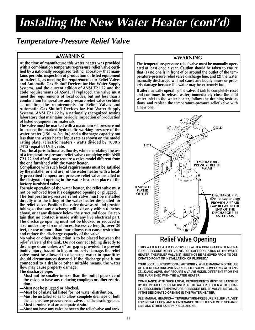
Temperature-Pressure Relief Valve
Installing the New Water Heater (cont’d)
TEMPERATURE-PRESSURE RELIEF
VALVE
DISCHARGE PIPE (Do not cap or plug)PROVIDE A 6″″ AIRGAP BETWEEN THE
END OF THEDISCHARGE PIPE
AND DRAIN
11
Relief Valve Opening"THIS WATER HEATER IS PROVIDED WITH A COMBINATION TEMPERA-TURE-PRESSURE RELIEF VALVE. FOR SAFE OPERATION OF THE WATERHEATER, THE RELIEF VALVE(S) MUST NOT BE REMOVED FROM ITS DES-IGNATED POINT OF INSTALLATION OR PLUGGED."
YOUR LOCAL JURISDICTIONAL AUTHORITY, WHILE MANDATING THE USEOF A TEMPERATURE-PRESSURE RELIEF VALVE COMPLYING WITH ANSIZ21.22 AND ASME, MAY REQUIRE A VALVE MODEL DIFFERENT FROM THEONE FURNISHED WITH THE WATER HEATER.
COMPLIANCE WITH SUCH LOCAL REQUIREMENTS MUST BE SATISFIEDBY THE INSTALLER OR END USER OF THE WATER HEATER WITH LOCAL-LY PRESCRIBED TEMPERATURE-PRESSURE RELIEF VALVE INSTALLEDIN THE DESIGNATED OPENING IN THE WATER HEATER.
SEE MANUAL HEADING—"TEMPERATURE-PRESSURE RELIEF VALVES"FOR INSTALLATION AND MAINTENANCE OF RELIEF VALVE. DISCHARGELINE AND OTHER SAFETY PRECAUTIONS.
COLD
TEMPEREDWATEROUTLET
HOT
WARNINGThe temperature-pressure relief valve must be manually oper-ated at least once a year. Caution should be taken to ensurethat (1) no one is in front of or around the outlet of the tem-perature-pressure relief valve discharge line, and (2) the watermanually discharged will not cause any bodily injury or prop-erty damage because the water may be extremely hot.If after manually operating the valve, it fails to completely resetand continues to release water, immediately close the coldwater inlet to the water heater, follow the draining instruc-tions, and replace the temperature-pressure relief valve witha new one.
WARNINGAt the time of manufacture this water heater was providedwith a combination temperature-pressure relief valve certi-fied by a nationally recognized testing laboratory that main-tains periodic inspection of production of listed equipmentor materials, as meeting the requirements for Relief Valvesand Automatic Gas Shutoff Devices for Hot Water SupplySystems, and the current edition of ANSI Z21.22 and thecode requirements of ASME. If replaced, the valve mustmeet the requirements of local codes, but not less than acombination temperature and pressure relief valve certifiedas meeting the requirements for Relief Valves andAutomatic Gas Shutoff Devices for Hot Water SupplySystems, ANSI Z21.22 by a nationally recognized testinglaboratory that maintains periodic inspection of productionof listed equipment or materials.The valve must be marked with a maximum set pressure notto exceed the marked hydrostatic working pressure of thewater heater (150 lbs./sq. in.) and a discharge capacity notless than the water heater input rate as shown on the modelrating plate. (Electric heaters - watts divided by 1000 x3412) equal BTU/Hr. rate.Your local jurisdictional authority, while mandating the useof a temperature-pressure relief valve complying with ANSIZ21.22 and ASME, may require a valve model different fromthe one furnished with the water heater.Compliance with such local requirements must be satisfiedby the installer or end user of the water heater with a local-ly prescribed temperature-pressure relief valve installed inthe designated opening in the water heater in place of thefactory furnished valve.For safe operation of the water heater, the relief valve mustnot be removed from it’s designated opening or plugged.The temperature-pressure relief valve must be installeddirectly into the fitting of the water heater designated forthe relief valve. Position the valve downward and providetubing so that any discharge will exit only within 6 inchesabove, or at any distance below the structural floor. Be cer-tain that no contact is made with any live electrical part.The discharge opening must not be blocked or reduced insize under any circumstances. Excessive length, over 30feet, or use of more than four elbows can cause restrictionand reduce the discharge capacity of the valve.No valve or other obstruction is to be placed between therelief valve and the tank. Do not connect tubing directly todischarge drain unless a 6″″ air gap is provided. To preventbodily injury, hazard to life, or property damage, the reliefvalve must be allowed to discharge water in quantitiesshould circumstances demand. If the discharge pipe is notconnected to a drain or other suitable means, the waterflow may cause property damage. The discharge pipe:—Must not be smaller in size than the outlet pipe size of
the valve, or have any reducing couplings or other restric-tion.
—Must not be plugged or blocked.—Must be of material listed for hot water distribution.—Must be installed so as to allow complete drainage of both
the temperature-pressure relief valve, and the discharge pipe.—Must terminate at an adequate drain.—Must not have any valve between the relief valve and tank.

Installing the New Water Heater (cont’d)
12
Filling the Water Heater
To fill the water heater with water:1. Close the water heater drain valve by turning the han-
dle to the right (clockwise). The drain valve is on thelower front of the water heater.
2. Open the cold water supply valve to the water heater.NOTE: The cold water supply valve must be left openwhen the water heater is in use.
3. To insure complete filling of the tank, allow air to exit byopening the nearest hot water faucet. Allow water to rununtil a constant flow is obtained. This will let air out ofthe water heater and the piping.
4. Check all new water piping for leaks. Repair as needed.
WiringThe water heater comes equipped with a 7 foot power cordwhich can be used to connect to a 110/120 volt powersource if, (1) local codes allow, and (2) there is a threeprong receptacle available. This unit must have a groundedoutlet to operate.
You must provide all wiring, (1) to a receptacle or, (2)between the water heater and junction box when thepower cord is not used.
OPTIONAL Field Installed Wiring
1. Provide a way to easily shut off the electric power whenworking on the water heater. This could be with a cir-cuit breaker or fuse block in the entrance box or a sepa-rate disconnect switch.
2. Install and connect a circuit directly from the main fuseor circuit breaker box. This circuit must be the right sizeand have its own fuse or circuit breaker.
5' MAXIMUMCORD LENGTH
(Factory supplied)
WIRE NUTS
GREENGROUND SCREW
CONDUIT
You must provide all wiring of the proper size outside ofthe water heater. You must obey local codes and electriccompany requirements when you install this wiring.
If you are not familiar with electric codes and practices, orif you have any doubt in your ability to connect the wiringto this water heater, obtain the service of a competent elec-trician. Contact a local electrical contractor and/or the localelectric utility.
7’ MAXIMUMCORD LENGTH
(Factory Supplied)
3. A standard 1/2″ conduit opening has been made in thewater heater junction box for the conduit connection.
4. Use wire nuts and connect the power supply wiring tothe wires inside the water heater’s junction box.
CAUTIONIf wiring from the fuse box or circuit breaker box was aluminumfor the old water heater, replace it with copper wire. If you wishto reuse the existing aluminum wire, have the connection at thewater heater made by a competent electrician. Contact a localelectrical contractor and/or the local electric utility.
WARNINGWATER HEATERS EQUIPPED FOR ONE TYPE VOLTAGEONLY: This water heater is equipped for 110/120 volts only.DO NOT USE THIS WATER HEATER WITH ANY VOLTAGEOTHER THAN THE ONE SHOWN ABOVE. Failure to use thecorrect voltage can cause problems which can result in DEATH,SERIOUS BODILY INJURY OR PROPERTY DAMAGE. If youhave nay questions or doubts consult your electric company.
WARNINGThis appliance must be grounded for safety and to insureproper operation. Failure to do so could result in DEATH,SERIOUS BODILY INJURY OR PROPERTY DAMAGE.
WARNINGDo not use an extension cord. If there is not a suitablereceptacle and/or local codes prohibit use of a power cord,field wiring must be provided.
CAUTIONNever use this water heater unless it is completely filledwith water. To prevent damage to the tank, the tank mustbe filled with water. Water must flow from the hot waterfaucet before turning “ON” gas to the water heater.
Installing the New Water Heater (cont’d)
13
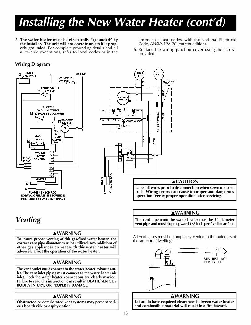
absence of local codes, with the National ElectricalCode, ANSI/NFPA 70 (current edition).
6. Replace the wiring junction cover using the screwsprovided.
Venting
All vent gases must be completely vented to the outdoors ofthe structure (dwelling).
Wiring Diagram
5. The water heater must be electrically “grounded” bythe installer. The unit will not operate unless it is prop-erly grounded. For complete grounding details and allallowable exceptions, refer to local codes or in the
WARNINGObstructed or deteriorated vent systems may present seri-ous health risk or asphyxiation.
WARNINGThe vent outlet must connect to the water heater exhaust out-let. The vent inlet piping must connect to the water heater airinlet. Both the water heater connections are clearly marked.Failure to read this instruction can result in DEATH, SERIOUSBODILY INJURY, OR PROPERTY DAMAGE.
WARNINGTo insure proper venting of this gas-fired water heater, thecorrect vent pipe diameter must be utilized. Any additions ofother gas appliances on vent with this water heater willadversely affect the operation of the water heater.
WARNINGThe vent pipe from the water heater must be 3″″ diametervent pipe and must slope upward 1/8 inch per five linear feet.
CAUTIONLabel all wires prior to disconnection when servicing con-trols. Wiring errors can cause improper and dangerousoperation. Verify proper operation after servicing.
WARNINGFailure to have required clearances between water heaterand combustible material will result in a fire hazard.
MIN. RISE 1/8″PER FIVE FEET

3 1/2'
STRAPPING
Installing the New Water Heater (cont’d)
14
Horizontal runs must be securely supported at 3 1/2 footintervals and vertical runs supported at 5 foot intervals.
Venting (cont’d)
WARNINGBe sure vent pipe is properly connected to preventescape of dangerous flue gases which could cause dead-ly asphyxiation.
WARNINGChemical vapor corrosion of the flue and vent systemmay occur if air for combustion contains certain chem-ical vapors. Spray can propellants, cleaning solvents,refrigerator and air conditioner refrigerants, swimmingpool chemicals, calcium and sodium chloride, waxes,bleach and process chemicals are typical compoundswhich are potentially corrosive.
VENTING THROUGH AN OUTSIDE WALLA. ALL 75 GALLON MODELS AND 50 GALLON 65,000
BTU/HR MODELSIn the carton is supplied:1. Two 3″ inlet and outlet PVC Schedule 40 - 45° vent caps.2. A 3″ ABS Schedule 40 - 90 street ell; used to connect the out-
let vent pipe to the water heater when the outlet vent pipe isto be turned horizontally directly off the blower.
3. A 5‘ section of 3″ ABS Schedule 40 outlet vent pipe (more maybe required and must be supplied locally).
1. The water heater requires its own (separate) ventingsystem.
2. Only 3″ ABS Schedule 40 piping and fittings are accept-able materials on the first five feet of the outlet vent system.
3. 3″ PCV, ABS, or CPVC Schedule 40 piping and fittings areacceptable materials for the inlet vent system and for theoutlet vent system after the first five feet.
4. It cannot be connected to existing vent piping or chimney.
5. When venting through an outside wall, the vents must ter-minate horizontally to the outdoors.
3″ PVC SCHEDULE40 90° STREETINLET ELBOWREQUIRED
5' SCHEDULE 40 ABS OUTLETPIPE SUPPLIED
SCHEDULE 40 PVC INLET PIPE
REQUIRED ONE 3″ SCHEDULE40 PVC 45° OUTLETELBOW SUPPLIED
ONE 3″ SCHEDULE40 PVC 45° INLETELBOW SUPPLIED
3″ ABS SCHEDULE 4090° STREETOUTLET ELBOWSUPPLIED
B. ALL 40 AND 50 GALLON 40,000 BTU/HR MODELS
In the carton is supplied:
1. Two 3″ inlet and outlet PVC Schedule 40 - 45° vent caps.
All other piping must be supplied by the supplier.
TWO 3″ PVC SCHEDULE40 90° STREETELBOWREQUIRED*
SCHEDULE 40 PVC INLET AND
OUTLET PIPEREQUIRED
ONE 3″ SCHEDULE40 PVC 45° INLETELBOW SUPPLIED
ONE 3″ SCHEDULE40 PVC 45° OUTLETELBOW SUPPLIED
1. The water heater requires its own (separate) ventingsystem.
2. 3″ PVC, ABS, or CPVC Schedule 40 piping and fittingsare acceptable materials for the vent system on all 40and 50 gallon models.
3. It cannot be connected to existing vent piping or chimney.
4. When venting through an outside wall, the vents mustterminate horizontally to the outdoors.
* If making an immediate horizontal run of vent off theblower, two 3″ PVC or ABS schedule 40 street elbowsare required
15
Installing the New Water Heater (cont'd)
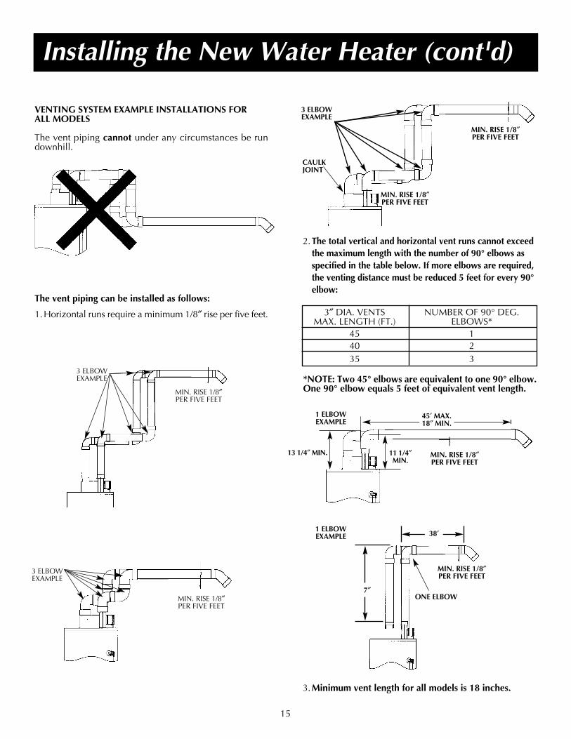
VENTING SYSTEM EXAMPLE INSTALLATIONS FORALL MODELS
The vent piping cannot under any circumstances be rundownhill.
The vent piping can be installed as follows:
1.Horizontal runs require a minimum 1/8″ rise per five feet.
3 ELBOWEXAMPLE
MIN. RISE 1/8″PER FIVE FEET
MIN. RISE 1/8″PER FIVE FEET
3 ELBOWEXAMPLE
*NOTE: Two 45° elbows are equivalent to one 90° elbow.One 90° elbow equals 5 feet of equivalent vent length.
MIN. RISE 1/8″PER FIVE FEET
13 1/4″ MIN. 11 1/4″MIN.
45′ MAX.18″ MIN.
ONE ELBOW
MIN. RISE 1/8″PER FIVE FEET
MIN. RISE 1/8″PER FIVE FEET
MIN. RISE 1/8″PER FIVE FEET
CAULKJOINT
3 ELBOWEXAMPLE
2.The total vertical and horizontal vent runs cannot exceedthe maximum length with the number of 90° elbows asspecified in the table below. If more elbows are required,the venting distance must be reduced 5 feet for every 90°elbow:
3″ DIA. VENTS NUMBER OF 90° DEG. MAX. LENGTH (FT.) ELBOWS*
45 140 235 3
1 ELBOWEXAMPLE
1 ELBOWEXAMPLE
7″
38′
3.Minimum vent length for all models is 18 inches.

MOVEMENT COMPLETE OF JOINT SET
90°F to 150°F 3/4 hr. 8 hrs.50°F to 90°F 1 hr. 15 hrs.
0°F to 50°F 1 1/3 hr. 18 hrs.
16
Cementing PVC, ABS OR CPVC Pipe and Fittings
Read and observe all safety information printed on primer,cleaner, and cement containers.
All primers, cleaners, and cements must meet all localcodes and applicable standards of the American SocietyFor Testing Materials Standards.
Before using primers, cleaners, and cements, stir or shake,making sure contents are liquid. Do not use if found to belumpy or jelly-like.1. Cut pipe ends squarely removing all burrs and dirt.2. Dry fit pipe and fittings to be connected for proper fit.3. Clean pipe and fitting with a primer/cleaner.4. Apply a thin coat of cement to fitting, avoiding puddling
inside.5. Apply a liberal coat of cement to pipe leaving no voids.6. QUICKLY assemble parts while cement is fluid! If you
wait too long, re-coat pipes.7. Push pipe completely into socket of fitting, turning as it
goes until it bottoms.8. Hold pipe and fitting together for 30 seconds. Then care-
fully clean off excess with a cloth. Allow connections asufficient time to cure before disturbing.
9. Remember that vent pipes must be adequately andsecurely supported.
APPROXIMATE SETTING TIME FOR 2 1/2″ TO 4″ PIPEJOINTS
Installing the New Water Heater (cont'd)
CUTTING OPENINGS THROUGH AN OUTSIDE WALLAND COLLAR INSTALLATION
After reading the manual and you have determined thelocation of the opening in the wall, (using the drawingbelow), cut one 3 1/2″ diameter hole for the inlet vent pip-ing and one 3 1/2″ diameter hole for the outlet vent pipingthrough an exterior wall.
NOTE: When determining location of the openings in theoutside wall allow for the 1/8″ rise per five feet that hastaken place in the horizontal run.
VENT PIPE SEPARATION
The inlet and outlet vent pipes must be separated by a min-imum distance of 6 1/2 inches up to 24 inches maximum.
6 1/2″ MIN.24″ MAX.
The 3″ PVC, ABS or CPVC Schedule 40 vent pipe can berun from the water heater through the wall or from the wallto the water heater, whichever is most convenient. The ventpipe must extend a minimum of 1 1/2″ through the exteri-or wall. Extending the vent cap as far as possible from thesurface of the exterior wall will help minimize discolorationof the wall. Note that the inside flue mounting adaptorsmust be slipped over the vent piping before locating thepipe through the wall. Before securing the inside and out-side collars to the wall, use a silicone sealer between pipeand opening to insure a water and air tight seal.
MIN. RISE 1/8″PER FIVE FEET
CL OF FLUE
11 1/2″ MIN.
40 GAL.– 481/2″50 GAL.– 571/2″50 GAL. (65,000 BTU) – 61″75 GAL.– 63″
PRECAUTIONSAlways store primers, cleaner, and cements in cool, dry,well ventilated places. Do not store them near heat,sparks, or flames. Keep containers closed. Use them inwell ventilated areas. Wear impervious clothing whilehandling. Do not smoke, eat, or drink while handling.Wash thoroughly after handling and before eating. Weareye protection when handling. If swallowed, drink water,do not induce vomiting, and call a physician or poisoncontrol center immediately. If inhaled, get fresh air andseek medical attention if ill feelings persist. In case of eyeand skin contact, immediately flush with plenty of waterfor 15 minutes and seek medical attention if irritationpersists. KEEP OUT OF REACH OF CHILDREN.
DANGERPrimer, cleaner, and cements are extremely flammable.They are harmful or fatal if swallowed. The vapors areharmful. They may irritate eyes and skin and can beabsorbed through the skin.

17
Installing the New Water Heater (cont'd)
Venting (cont'd)
INSTALLATION SHOWING USE OF PVC, ABS ORCPVC PIPE FOR INLET AND OUTLET VENT PIPING:
Inlet piping through any type wall.
EXTERIOR WALLSILICONESEALER
SILICONE SEALER
SCREW
SCREW
SCREW
SCREW SCREEN ATOUTLET
FLUE MOUNTINGADAPTOR
VENT CAP MUSTBE POSITIONEDDOWNWARD
11¼2″″ MIN. EXTEN-SION THROUGHEXTERIOR WALL
FLUE MOUNTING ADAPTOR
CONNECTING VENT TO BLOWER
1. If making an immediate horizontal run of vent off theblower, one 3″ PVC inlet and one 3″ PVC (ABS for 75Gal. Models and 50 Gal. 65,000 Btu/Hr Models) outletSchedule 40 street elbows are required. Place the elbowin the required direction on the blower and using 3 sheetmetal screws, attach the elbow.
2. If there is to be a vertical run of vent from the blower, the3″ PVC inlet and the 3″ PVC (ABS for 75 Gal. Modelsand 50 Gal. 65,000 Btu/Hr Models) outlet pipes mustbe attached to the blower and venting hood, using 6sheet metal screws.
CAULKJOINTS
CAULKJOINTS
VENT TOOUTDOORS
INTAKE FORCOMBUSTION AIR
FLUE PRODUCTSDISCHARGE PIPE
AIR INTAKEPIPE
INSTALLATION SHOWING USE OF (OPTIONAL)DELUXE HORIZONTAL VENT KIT:
Typical installation.
If this concentric flue, through the wall type of venting sys-tem is preferred, the vent kit can be ordered from theService Parts Dept. under kit #9002749. See also pages 34to 37. Installation instructions are provided with the kit.
VENTING THROUGH A ROOF
Two 3″ inlet and outlet PVC Schedule 40 45° vent caps aresupplied.
A 5’ section of 3″ ABS Schedule 40 outlet vent pipe (75 Gal.Models and 50 Gal. 65,000 Btu/Hr Models only) is sup-plied. (More may be required and must be supplied locally).
1. The water heater requires its own (separate) ventingsystem.

Installing the New Water Heater (cont’d)
A gas line of sufficient size must be run to the water heater.Consult the current edition of National Fuel Gas Code ANSIZ223.1, also referred to as NFPA 54 and the gas companyconcerning pipe size.
There must be:—A readily accessible manual shut off valve in the gas sup-
ply line serving the water heater, and—A drip leg (sediment trap) ahead of the gas control valve
to help prevent dirt and foreign materials from enteringthe gas control valve.
—A flexible gas connector or a ground joint union betweenthe shutoff valve and control valve to permit servicing ofthe unit.
Be sure to check all the gas piping for leaks before lightingthe water heater. Use a soapy water solution, not a matchor open flame. Rinse off soapy solution and wipe dry.
When installed at elevations above 2,000 feet, input rat-ings should be reduced at the rate of 4 percent for each1,000 feet above sea level which requires replacement ofthe burner orifice in accordance with the National Fuel GasCode ANSI Z223.1 / NFPA 54. Contact your local gas util-ity for further information.
Gas Piping
WARNINGMake sure the gas supplied is the same type listed on themodel rating plate. The inlet gas pressure must notexceed 10.5 in. water column (2.6kPa)for natural gas or13 in. water column (3.2 kPa) for propane (L.P.) gas. Theminimum inlet gas pressure listed on the rating plate isfor the purpose of input adjustment.
WARNINGIf the gas control valve is subjected to pressure exceed-ing 1/2 pound per square inch (3.5kPa), the damage tothe gas control valve could result in a fire or explosionfrom leaking gas.
WARNINGIf the main gas line shutoff serving all gas appliances isused, also turn “OFF” the gas at each appliance. Leave allgas appliances turned “OFF” until the water heater instal-lation is complete.
VENTING THROUGH A ROOF (CONT’D)
2. Only 3″ ABS Schedule 40 piping and fittings are acceptablematerials on the first five feet of the outlet vent system of 75Gal. Models and 50 Gal. 65,000 Btu/Hr Models only.
3. 3″ PVC, ABS, or CPVC Schedule 40 piping and fittings areacceptable materials for the inlet vent system and for the out-let vent system (after the first five feet for 75 Gal. Models and50 Gal. 65,000 Btu/Hr Models only).
4. It cannot be connected to existing vent piping or chimney.
5. It must terminate vertically to the outdoors.
6. The total vertical and horizontal vent runs cannot exceed themaximum length with a maximum number of 90° elbows asspecified in the table below. If more elbows are required, theventing distance must be reduced 5 feet for every 90° elbow.
18
3″ DIA. VENTS NUMBER OF 90° DEG. MAX. LENGTH (FT.) ELBOWS*
45 140 235 3
*NOTE: Two 45° elbows are equivalent to one 90° elbow.One 90° elbow equals 5 feet of equivalent vent length.
VENT PIPE SEPARATION
The inlet and outlet vent pipes must be separated by a min-imum distance of 6 1/2 inches up to 24 inches maximum.
TOTAL VERTICAL ANDHORIZONTAL RUNS - SEECHART ABOVE (ITEM 6).
WARNINGFailure to replace the orifice could result in improper andinefficient operation of the appliance, producing carbonmonoxide gas in excess of safe limits, which could result inserious injury or death. Contact your gas supplier for anyspecific changes which may be required in your area.
19
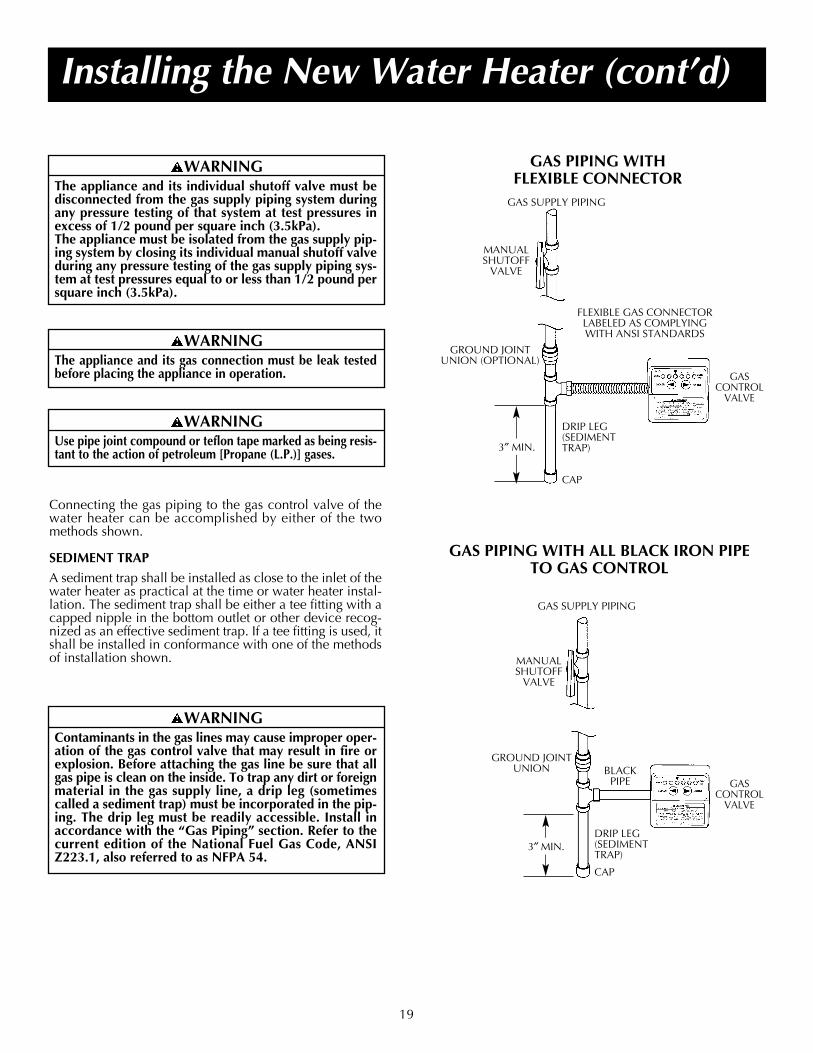
Connecting the gas piping to the gas control valve of thewater heater can be accomplished by either of the twomethods shown.
SEDIMENT TRAP
A sediment trap shall be installed as close to the inlet of thewater heater as practical at the time or water heater instal-lation. The sediment trap shall be either a tee fitting with acapped nipple in the bottom outlet or other device recog-nized as an effective sediment trap. If a tee fitting is used, itshall be installed in conformance with one of the methodsof installation shown.
Installing the New Water Heater (cont’d)
GAS PIPING WITH FLEXIBLE CONNECTOR
GAS PIPING WITH ALL BLACK IRON PIPETO GAS CONTROL
WARNINGContaminants in the gas lines may cause improper oper-ation of the gas control valve that may result in fire orexplosion. Before attaching the gas line be sure that allgas pipe is clean on the inside. To trap any dirt or foreignmaterial in the gas supply line, a drip leg (sometimescalled a sediment trap) must be incorporated in the pip-ing. The drip leg must be readily accessible. Install inaccordance with the “Gas Piping” section. Refer to thecurrent edition of the National Fuel Gas Code, ANSIZ223.1, also referred to as NFPA 54.
WARNINGUse pipe joint compound or teflon tape marked as being resis-tant to the action of petroleum [Propane (L.P.)] gases.
WARNINGThe appliance and its gas connection must be leak testedbefore placing the appliance in operation.
WARNINGThe appliance and its individual shutoff valve must bedisconnected from the gas supply piping system duringany pressure testing of that system at test pressures inexcess of 1/2 pound per square inch (3.5kPa).The appliance must be isolated from the gas supply pip-ing system by closing its individual manual shutoff valveduring any pressure testing of the gas supply piping sys-tem at test pressures equal to or less than 1/2 pound persquare inch (3.5kPa).
GAS SUPPLY PIPING
MANUALSHUTOFF
VALVE
GAS CONTROL
VALVE
GROUND JOINTUNION BLACK
PIPE
DRIP LEG (SEDIMENTTRAP)
CAP
3″ MIN.
GROUND JOINTUNION (OPTIONAL)
MANUALSHUTOFF
VALVE
GAS CONTROL
VALVE
GAS SUPPLY PIPING
FLEXIBLE GAS CONNECTORLABELED AS COMPLYINGWITH ANSI STANDARDS
DRIP LEG (SEDIMENT TRAP)
CAP
3″ MIN.
20
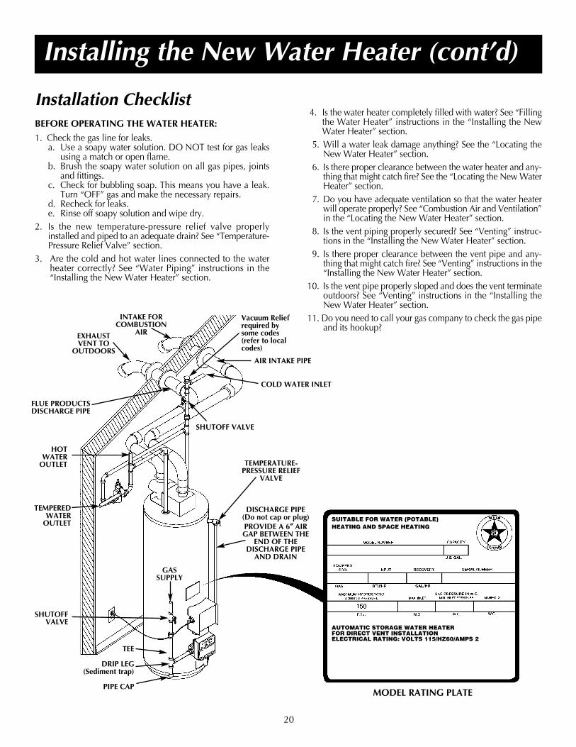
Installation ChecklistBEFORE OPERATING THE WATER HEATER:
1. Check the gas line for leaks.a. Use a soapy water solution. DO NOT test for gas leaks
using a match or open flame.b. Brush the soapy water solution on all gas pipes, joints
and fittings.c. Check for bubbling soap. This means you have a leak.
Turn “OFF” gas and make the necessary repairs.d. Recheck for leaks.e. Rinse off soapy solution and wipe dry.
2. Is the new temperature-pressure relief valve properlyinstalled and piped to an adequate drain? See “Temperature-Pressure Relief Valve” section.
3. Are the cold and hot water lines connected to the waterheater correctly? See “Water Piping” instructions in the“Installing the New Water Heater” section.
Installing the New Water Heater (cont’d)
MODEL RATING PLATE
4. Is the water heater completely filled with water? See “Fillingthe Water Heater” instructions in the “Installing the NewWater Heater” section.
5. Will a water leak damage anything? See the “Locating theNew Water Heater” section.
6. Is there proper clearance between the water heater and any-thing that might catch fire? See the “Locating the New WaterHeater” section.
7. Do you have adequate ventilation so that the water heaterwill operate properly? See “Combustion Air and Ventilation”in the “Locating the New Water Heater” section.
8. Is the vent piping properly secured? See “Venting” instruc-tions in the “Installing the New Water Heater” section.
9. Is there proper clearance between the vent pipe and any-thing that might catch fire? See “Venting” instructions in the“Installing the New Water Heater” section.
10. Is the vent pipe properly sloped and does the vent terminateoutdoors? See “Venting” instructions in the “Installing theNew Water Heater” section.
11. Do you need to call your gas company to check the gas pipeand its hookup?
COLD WATER INLET
HOTWATER
OUTLET
TEMPEREDWATER
OUTLET
SHUTOFFVALVE
TEE
DRIP LEG(Sediment trap)
PIPE CAP
EXHAUSTVENT TO
OUTDOORS
GASSUPPLY
TEMPERATURE-PRESSURE RELIEF
VALVE
DISCHARGE PIPE (Do not cap or plug)PROVIDE A 6″″ AIRGAP BETWEEN THE
END OF THE DISCHARGE PIPE
AND DRAIN
INTAKE FORCOMBUSTION
AIR
FLUE PRODUCTSDISCHARGE PIPE
AIR INTAKE PIPE
Vacuum Reliefrequired bysome codes (refer to localcodes)
SHUTOFF VALVE
SUITABLE FOR WATER (POTABLE)HEATING AND SPACE HEATING
AUTOMATIC STORAGE WATER HEATERFOR DIRECT VENT INSTALLATIONELECTRICAL RATING: VOLTS 115/HZ60/AMPS 2
21
Operating
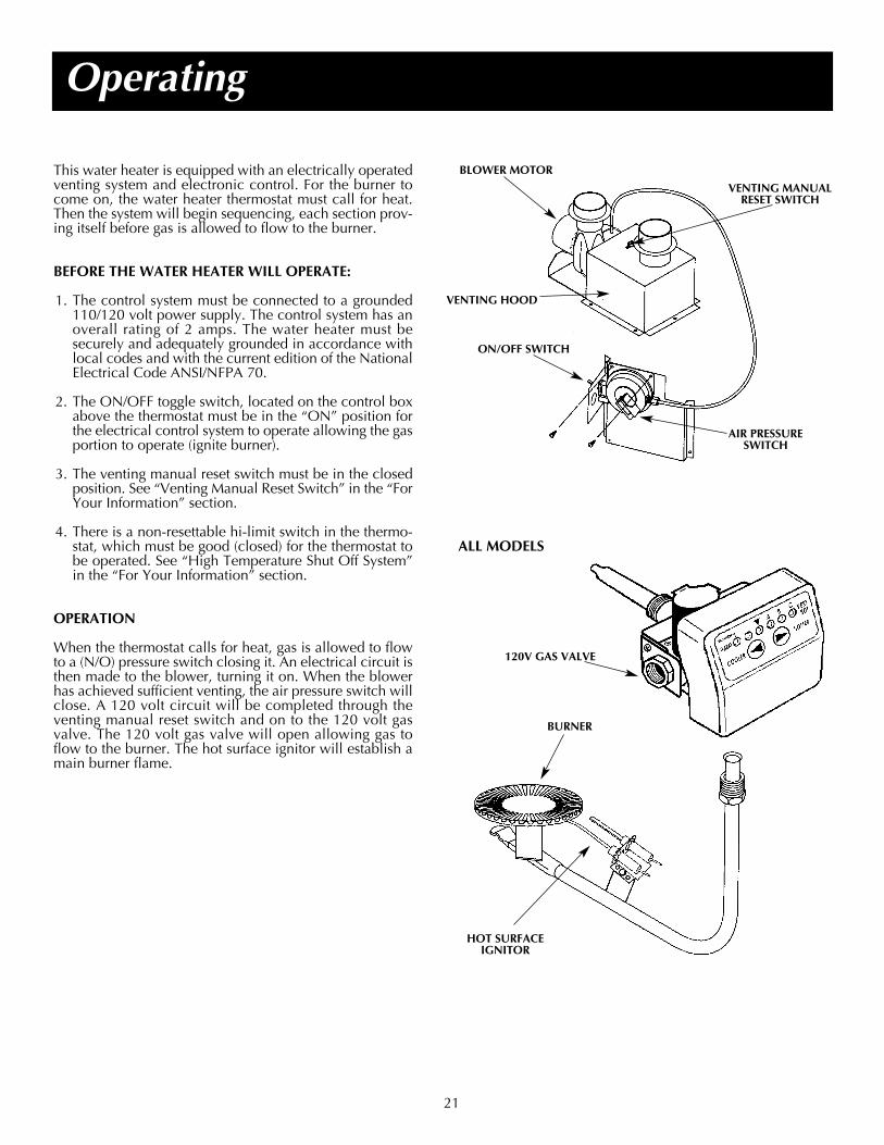
This water heater is equipped with an electrically operatedventing system and electronic control. For the burner tocome on, the water heater thermostat must call for heat.Then the system will begin sequencing, each section prov-ing itself before gas is allowed to flow to the burner.
BEFORE THE WATER HEATER WILL OPERATE:
1. The control system must be connected to a grounded110/120 volt power supply. The control system has anoverall rating of 2 amps. The water heater must besecurely and adequately grounded in accordance withlocal codes and with the current edition of the NationalElectrical Code ANSI/NFPA 70.
2. The ON/OFF toggle switch, located on the control boxabove the thermostat must be in the “ON” position forthe electrical control system to operate allowing the gasportion to operate (ignite burner).
3. The venting manual reset switch must be in the closedposition. See “Venting Manual Reset Switch” in the “ForYour Information” section.
4. There is a non-resettable hi-limit switch in the thermo-stat, which must be good (closed) for the thermostat tobe operated. See “High Temperature Shut Off System”in the “For Your Information” section.
OPERATION
When the thermostat calls for heat, gas is allowed to flowto a (N/O) pressure switch closing it. An electrical circuit isthen made to the blower, turning it on. When the blowerhas achieved sufficient venting, the air pressure switch willclose. A 120 volt circuit will be completed through theventing manual reset switch and on to the 120 volt gasvalve. The 120 volt gas valve will open allowing gas toflow to the burner. The hot surface ignitor will establish amain burner flame.
BLOWER MOTOR
AIR PRESSURESWITCH
VENTING HOOD
ON/OFF SWITCH
VENTING MANUALRESET SWITCH
BURNER
120V GAS VALVE
HOT SURFACEIGNITOR
ALL MODELS

22
Operating (cont’d)
Operating instructions are located on front of the waterheater, above or to one side of the gas control valve. Seepage 23.
CHECK FOR LEAKS
Be sure to check all your gas pipes for leaks before operat-ing your water heater. Use a soapy water solution, not amatch or open flame. Check the factory gas fittings whenthe main burner is turned “ON”.
WATER HEATING IGNITION SEQUENCE(Make sure gas and electric power are connected properly)
1. The ignition control module is powered and monitors thesystem, waiting for a call for heat from the thermostat.
2. The thermostat calls for heat by reading a resistancevalue within a given range directly proportional towater temperature.
WARNINGBEFORE OPERATING [PROPANE (L.P.) GAS WATERHEATERS]: Propane (L.P.) gas is heavier than air. Shouldthere be a leak in the system, the gas will settle near theground. Basements, crawl spaces, skirted areas undermanufactured (mobile) homes (even when ventilated),closets and areas below ground level will serve as pock-ets for the accumulation of this gas. Before attemptingto operate the water heater or turning a nearby electri-cal light switch, be absolutely sure there is no accumu-lated gas in the area. Search for odor of gas by sniffingat ground level in the vicinity of the appliance. If odoris detected, follow the steps indicated at “For YourSafety” on the cover page of this manual, then leave thepremises.
WARNINGAN ODORANT IS ADDED TO THE GAS USED BY
THIS WATER HEATER.FOR YOUR SAFETYIF YOU SMELL GAS:1. Do not try to light any appliance.2. Do not touch any electrical switch; do not use any
phone in your building.3. Immediately call you gas supplier from a neighbor’s
phone. Follow the gas supplier’s instructions.4. If you cannot reach your gas supplier, call the fire
department.
3. The control module:
a) Checks the pressure switch for an open circuit.b) Energizes the blower.c) Checks the pressure switch for a closed circuit to
prove draft.d) Sends line voltage to the hot surface igniter with a
20-second warm up period.e) Opens the gas valve and checks the sensing rod for
flame.
4. The burner heats the water to the desired thermostat setting.
a) The resistance in the thermostat rises to the valueselected by the temperature control knob.
b) The control module closes the gas valve and 5 seconds later, removes power from the blower.
5. Cycle is completed.
CONTROL SEQUENCE - HOT SURFACE DIRECT IGNITIONPre-purge 5 sec.HSI Warm-up 20 sec.Ignition Activation Period 4 sec.Flame Recognition Period 1sec.Ignition Trial 4 sec.Interpurge 5 sec.Post-purge 5 sec.Retries 2 Reset from Lockout 1 hr.Flame Sensing (Nominal) HSI Off/Run Mode 4.0 µ DC

23
Operating (cont’d)
5. This appliance is equipped with a device which auto-matically lights the burner.DO NOT TRY TO LIGHT THE BURNER BY HAND.
6. Wait five (5) minutes to clear out any gas.If you then smell gas, STOP! Follow “B” inthe safety information above on this label. If you don’tsmell gas, go to the next step.
7. Turn on all electrical power to the appliance.8. Set the ON/OFF switch on the control box to the
“ON” position.9. Set the thermostat to desired setting by first pressing
the COOLER and HOTTER buttons togetherand holding for 1 second. Then press the HOTTERbutton .
10. WATER TEMPERATURE ADJUSTMENT isapproximately 120°F.
CAUTION: Hotter water increases the risk of scald injury. Consult the instruction manual before changing temperature.
11. If the appliance will not operate, follow the instruc-tions “TO TURN OFF GAS TO APPLIANCE” andcall your technician or gas supplier.
WARNING: TURN OFF ALL ELECTRIC POWER BEFORE SERVICING
1. STOP! Read the safety information aboveon this label.
2. Set the ON/OFF switch on the control box to the“ON” position.
3. Set the thermostat to the lowest setting by first press-ing the COOLER and HOTTER buttonstogether and holding for 1 second. Then press theCOOLER button until the WARM indicator lightappears.
4. Set the ON/OFF switch on the control box to the“OFF” position.
BEFORE OPERATING: ENTIRE SYSTEM MUST BE FILLED WITH WATER AND AIR PURGED FROM ALL LINES.
1. Set thermostat to the lowest setting by first pressingthe COOLER and HOTTER buttons togetherand holding for 1 second. Then press the COOLERbutton until the WARM indicator light appears.
2. Set the ON/OFF switch on the control box to the“OFF” position.
3. Turn off all electric power to the appliance if serviceis to be performed.
• If you cannot reach your gas supplier, call the firedepartment.
C. Use only your hand to push in the gas control but-tons. Never use tools. If the control buttons will notpush in, don’t try to repair them, call a qualified ser-vice technician. Force or attempted repair mayresult in a fire or explosion.
D. Do not use this appliance if any part has been underwater. Immediately contact a qualified installer orservice agency to replace a flooded water heater.Do not attempt to repair the unit! It must bereplaced!
A. This appliance does not have a pilot. It is equippedwith an ignition device which automatically lights theburner. Do NOT try to light the burner by hand.
B. BEFORE OPERATING smell all around the appliance area for gas. Be sure to smell next to thefloor because some gas is heavier than air and willsettle on the floor.
WHAT TO DO IF YOU SMELL GAS:• Do not try to light any appliance.• Do not touch any electric switch;
do not use any phone in your building.• Immediately call your gas supplier from a neighbor’s
phone. Follow the gas supplier’s instructions.
WARNING: If you do not follow these instructions exactly, a fire orexplosion may result causing property damage, personal injury or lossof life.
TO TURN OFF GAS TO APPLIANCE
OPERATING INSTRUCTIONS
FOR YOUR SAFETY READ BEFORE OPERATING
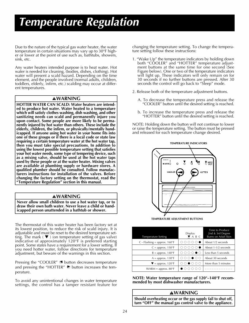
24
Temperature Regulation
Due to the nature of the typical gas water heater, the watertemperature in certain situations may vary up to 30°F high-er or lower at the point of use such as, bathtubs, showers,sink, etc.
Any water heaters intended purpose is to heat water. Hotwater is needed for cleaning, (bodies, dishes, clothing). Hotwater will present a scald hazard. Depending on the timeelement, and the people involved (normal adults, children,toddlers, elderly, infirm, etc.) scalding may occur at differ-ent temperatures.
The thermostat of this water heater has been factory set atits lowest position, to reduce the risk of scald injury. It isadjustable and must be reset to the desired temperature set-ting. The mark ( ) (on temperature setting of gas valve)indicative of approximately 120°F is preferred startingpoint. Some states have a requirement for a lower setting. Ifyou need hotter water, follow directions for temperatureadjustment, but beware of the warnings in this section.
Pressing the “COOLER” button decreases temperatureand pressing the “HOTTER” button increases the tem-perature.
To avoid any unintentional changes in water temperaturesettings, the control has a tamper resistant feature for
NOTE: Water temperature range of 120°–140°F recom-mended by most dishwasher manufacturers.
WARNINGHOTTER WATER CAN SCALD: Water heaters are intend-ed to produce hot water. Water heated to a temperaturewhich will satisfy clothes washing, dish washing, and othersanitizing needs can scald and permanently injure youupon contact. Some people are more likely to be perma-nently injured by hot water than others. These include theelderly, children, the infirm, or physically/mentally hand-icapped. If anyone using hot water in your home fits intoone of these groups or if there is a local code or state lawrequiring a certain temperature water at the hot water tap,then you must take special precautions. In addition tousing the lowest possible temperature setting that satisfiesyour hot water needs, some type of tempering device, suchas a mixing valve, should be used at the hot water tapsused by these people or at the water heater. Mixing valvesare available at plumbing supply or hardware stores. Aqualified plumber should be consulted. Follow manufac-turers instructions for installation of the valves. Beforechanging the factory setting on the thermostat, read the“Temperature Regulation” section in this manual.
WARNINGNever allow small children to use a hot water tap, or todraw their own bath water. Never leave a child or hand-icapped person unattended in a bathtub or shower.
WARNINGShould overheating occur or the gas supply fail to shut off,turn “OFF” the manual gas control valve to the appliance.
C - Flashing = approx. 160°F About 1/2 seconds
C = approx. 150°F About 1-1/2 seconds
B = approx. 140°F Less than 5 seconds
A = approx. 130°F About 30 seconds
= approx. 120°F More than 5 minutes
WARM = approx. 80°F - - - - - - - - - - - - - - - -
Time to ProduceDisplay 2nd & 3rd Degree
Temperature Setting A B C Burns on Adult Skin
TEMPERATURE INDICATORS
TEMPERATURE ADJUSTMENT BUTTONS
changing the temperature setting. To change the tempera-ture setting follow these instructions:
1. “Wake Up” the temperature indicators by holding downboth “COOLER” and “HOTTER” temperature adjust-ment buttons at the same time for one second (SeeFigure below). One or two of the temperature indicatorswill light up. These indicators will only remain on for30 seconds if no further buttons are pressed. After 30seconds the control will go back to “Sleep” mode.
2. Release both of the temperature adjustment buttons.
A. To decrease the temperature press and release the“COOLER” button until the desired setting is reached.
b. To increase the temperature press and release the“HOTTER” button until the desired setting is reached.
NOTE: Holding down the button will not continue to loweror raise the temperature setting. The button must be pressedand released for each temperature change desired.

25
Start Up ConditionsCONDENSATIONWhenever the water heater is filled with cold water, a cer-tain amount of condensation will form while the burner ison. A water heater may appear to be leaking when in factthe water is condensing. This usually happens when:
a. When a new water heater is filled with cold water forthe first time.
b. When gas burns and water vapor is produced in waterheaters, particularly high efficiency models where fluetemperatures are lower.
c. When you use large amounts of hot water in a shorttime and the refill water is very cold.
Moisture from the products of combustion condenses onthe cooler tank surfaces and form drops of water which mayfall onto the burner or other hot surfaces and produce a“sizzling” or “frying” noise.
Because of the suddenness and amount of water, conden-sation water may be diagnosed as a “tank leak”. After thewater in the tank warms up (about 1-2 hours), the condi-tion should disappear.
Do not assume the water heater is leaking until there hasbeen enough time for the water in the tank to warm up.
An undersized water heater will cause more condensation.The water heater must be sized properly to meet the fami-ly’s demands for hot water including dishwashers, washingmachines and shower heads.
Excessive condensation may be noticed during the winterand early spring months when incoming water tempera-tures are at their lowest.
Good venting is essential for a gas fired water heater tooperate properly as well as to carry away products of com-bustion and water vapor.
SMOKE/ODORIt is not uncommon to experience a small amount of smokeand odor during the initial start-up. This is due to burningoff of oil from metal parts, and will disappear in a shortwhile.
THERMAL EXPANSIONBecause of such events as high line pressure, frequent cut-offs, the effects of water hammer among others, water sup-ply systems may have installed devices such as pressurereducing valves, check valves, back flow preventers, etc...tocontrol these types of problems. When these devices arenot equipped with an internal by-pass, and no other mea-sures are taken, the devices cause the water system to beclosed. As water is heated, it expands (thermal expansion)and closed systems do not allow for the expansion of heat-ed water.The water within the water heater tank expands as it is heat-ed and increases the pressure of the water system. If therelieving point of the water heater’s temperature-pressurerelief valve is reached, the valve will relieve the excess pres-sure. The temperature-pressure relief valve is not intendedfor the constant relief of thermal expansion. This is anunacceptable condition and must be corrected.
It is recommended that any devices installed which couldcreate a closed system have a by-pass and/or the systemhave an expansion tank to relieve the pressure built by ther-mal expansion in the water system. Expansion tanks areavailable for ordering through local plumbing supply hous-es. Contact the local water supplier and/or plumbing con-tractor for assistance in controlling these situations.
STRANGE SOUNDSPossible noises due to expansion and contraction of somemetal parts during periods of heat-up and cool-down do notrepresent harmful or dangerous conditions.Condensation causes sizzling and popping with the burnerarea during heating and cooling periods and should be con-sidered normal. See “Condensation” in this section.
Operational ConditionsSMELLY WATERIn each water heater there is installed at least one anoderod (see parts section) for corrosion protection of the tank.Certain water conditions will cause a reaction between thisrod and the water. The most common complaint associatedwith the anode rod is one of a “rotten egg smell”. This odoris derived from hydrogen sulfide gas dissolved in the water.The smell is the result of four factors which must all be pre-sent for the odor to develop:
a. a concentration of sulfate in the supply water.b. little or no dissolved oxygen in the water.c. a sulfate reducing bacteria within the water heater.
(This harmless bacteria is non-toxic to humans.)d. an excess of active hydrogen in the tank. This is caused
by the corrosion protective action of the anode.
Smelly water may be eliminated or reduced in some waterheater models by replacing the anode(s) with one of lessactive material, and then chlorinating the water heater tankand all hot water lines. Contact the local water heater sup-plier for further information concerning an AnodeReplacement Kit #9000029 and this ChlorinationTreatment.
If the smelly water persists after the anode replacement andchlorination treatment, we can only suggest that continu-ous chlorination and filtering conditioning equipment beconsidered to eliminate the water problem.
Do not remove the anode leaving the tank unprotected.By doing so, all warranty on the water heater tank is voided.
For Your Information

26
For Your Information (cont’d)Operational Conditions (cont’d)“AIR” IN HOT WATER FAUCETS
VENTING MANUAL RESET SWITCHThere is a venting manual reset switch located on the vent-ing hood. If the switch is activated, it will not reset itself.Before resetting this reset switch, check for flue blockageand propriety of the venting system. To reset, press the redbutton.
BLOWER MOTOR VENTING MANUALRESET SWITCH
VENTING HOOD
WARNINGHYDROGEN GAS: Hydrogen gas can be produced in ahot water system that has not been used for a long periodof time (generally two weeks or more). Hydrogen gas isextremely flammable and explosive. To prevent the pos-sibility of injury under these conditions, we recommendthe hot water faucet be opened for several minutes at thekitchen sink before any electrical appliances which areconnected to the hot water system are used (such as adishwasher or washing machine). If hydrogen gas is pre-sent, there will probably be an unusual sound similar toair escaping through the pipe as the hot water faucet isopened. There must be no smoking or open flame nearthe faucet at the time it is open.
HIGH TEMPERATURE LIMIT SWITCH(Single-Use Type Energy Cut Off)The thermostat has a built-in limit switch which will actuatein case of excessive water temperatures. The heater cannotbe relit until the gas control valve is replaced. It is importantthat a serviceman be called to determine the reason for limitoperation and thus avoid repeated thermostat replacement.Lower the temperature adjustment setting on new control.
NOT ENOUGH OR NO HOT WATER1. Check the manual gas shut off valve to be sure it is open.
2. The ON/OFF switch on the control box must be “ON”.
3. The temperature button adjustment may be set too low.See the “Temperature Regulation” section.
4. The gas company can check the gas input to see if it iscorrect. An underfired water heater will not heat water asquickly.
5. Look for leaking or open hot water faucet’s. Make sureall are closed.
6. The cold water inlet temperature may be colder duringthe winter months. It will take longer to heat the waterand seem like less hot water.
7. If you cannot find what is wrong, call the local gas util-ity and/or plumbing contractor.
WATER IS TOO HOT
1. The temperature adjustment setting may be set too high.See the “Temperature Regulation” section.
NOTE: A period of time is necessary after an adjust-ment has been made for the water temperature toreach the new temperature setting.
2. If lower temperature settings will not lower the watertemperature, call the local gas utility.
WARNINGShould overheating occur or the gas supply fail to shutoff, turn “off” the manual gas control valve to theappliance.
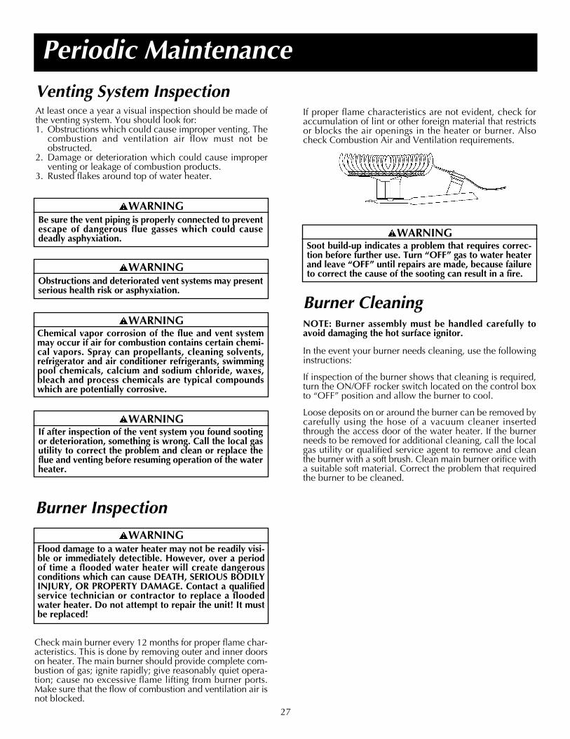
27
Periodic MaintenanceVenting System InspectionAt least once a year a visual inspection should be made ofthe venting system. You should look for:1. Obstructions which could cause improper venting. The
combustion and ventilation air flow must not beobstructed.
2. Damage or deterioration which could cause improperventing or leakage of combustion products.
3. Rusted flakes around top of water heater.
Burner Inspection
WARNINGSoot build-up indicates a problem that requires correc-tion before further use. Turn “OFF” gas to water heaterand leave “OFF” until repairs are made, because failureto correct the cause of the sooting can result in a fire.
WARNINGFlood damage to a water heater may not be readily visi-ble or immediately detectible. However, over a periodof time a flooded water heater will create dangerousconditions which can cause DEATH, SERIOUS BODILYINJURY, OR PROPERTY DAMAGE. Contact a qualifiedservice technician or contractor to replace a floodedwater heater. Do not attempt to repair the unit! It mustbe replaced!
WARNINGIf after inspection of the vent system you found sootingor deterioration, something is wrong. Call the local gasutility to correct the problem and clean or replace theflue and venting before resuming operation of the waterheater.
WARNINGChemical vapor corrosion of the flue and vent systemmay occur if air for combustion contains certain chemi-cal vapors. Spray can propellants, cleaning solvents,refrigerator and air conditioner refrigerants, swimmingpool chemicals, calcium and sodium chloride, waxes,bleach and process chemicals are typical compoundswhich are potentially corrosive.
WARNINGObstructions and deteriorated vent systems may presentserious health risk or asphyxiation.
WARNINGBe sure the vent piping is properly connected to preventescape of dangerous flue gasses which could causedeadly asphyxiation.
Burner CleaningNOTE: Burner assembly must be handled carefully toavoid damaging the hot surface ignitor.
In the event your burner needs cleaning, use the followinginstructions:
If inspection of the burner shows that cleaning is required,turn the ON/OFF rocker switch located on the control boxto “OFF” position and allow the burner to cool.
Loose deposits on or around the burner can be removed bycarefully using the hose of a vacuum cleaner insertedthrough the access door of the water heater. If the burnerneeds to be removed for additional cleaning, call the localgas utility or qualified service agent to remove and cleanthe burner with a soft brush. Clean main burner orifice witha suitable soft material. Correct the problem that requiredthe burner to be cleaned.
If proper flame characteristics are not evident, check foraccumulation of lint or other foreign material that restrictsor blocks the air openings in the heater or burner. Alsocheck Combustion Air and Ventilation requirements.
Check main burner every 12 months for proper flame char-acteristics. This is done by removing outer and inner doorson heater. The main burner should provide complete com-bustion of gas; ignite rapidly; give reasonably quiet opera-tion; cause no excessive flame lifting from burner ports.Make sure that the flow of combustion and ventilation air isnot blocked.
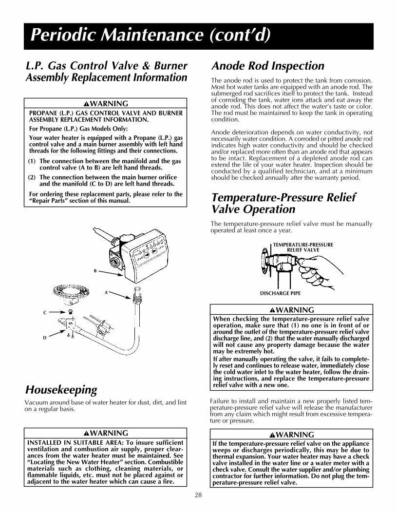
28
Periodic Maintenance (cont’d)
Failure to install and maintain a new properly listed tem-perature-pressure relief valve will release the manufacturerfrom any claim which might result from excessive tempera-ture or pressure.
Temperature-Pressure ReliefValve OperationThe temperature-pressure relief valve must be manuallyoperated at least once a year.
TEMPERATURE-PRESSURERELIEF VALVE
DISCHARGE PIPE
HousekeepingVacuum around base of water heater for dust, dirt, and linton a regular basis.
WARNINGINSTALLED IN SUITABLE AREA: To insure sufficientventilation and combustion air supply, proper clear-ances from the water heater must be maintained. See“Locating the New Water Heater” section. Combustiblematerials such as clothing, cleaning materials, orflammable liquids, etc. must not be placed against oradjacent to the water heater which can cause a fire.
WARNINGWhen checking the temperature-pressure relief valveoperation, make sure that (1) no one is in front of oraround the outlet of the temperature-pressure relief valvedischarge line, and (2) that the water manually dischargedwill not cause any property damage because the watermay be extremely hot.If after manually operating the valve, it fails to complete-ly reset and continues to release water, immediately closethe cold water inlet to the water heater, follow the drain-ing instructions, and replace the temperature-pressurerelief valve with a new one.
WARNINGIf the temperature-pressure relief valve on the applianceweeps or discharges periodically, this may be due tothermal expansion. Your water heater may have a checkvalve installed in the water line or a water meter with acheck valve. Consult the water supplier and/or plumbingcontractor for further information. Do not plug the tem-perature-pressure relief valve.
Anode Rod InspectionThe anode rod is used to protect the tank from corrosion.Most hot water tanks are equipped with an anode rod. Thesubmerged rod sacrifices itself to protect the tank. Insteadof corroding the tank, water ions attack and eat away theanode rod. This does not affect the water’s taste or color.The rod must be maintained to keep the tank in operatingcondition.
Anode deterioration depends on water conductivity, notnecessarily water condition. A corroded or pitted anode rodindicates high water conductivity and should be checkedand/or replaced more often than an anode rod that appearsto be intact. Replacement of a depleted anode rod canextend the life of your water heater. Inspection should beconducted by a qualified technician, and at a minimumshould be checked annually after the warranty period.
L.P. Gas Control Valve & BurnerAssembly Replacement Information
WARNINGPROPANE (L.P.) GAS CONTROL VALVE AND BURNERASSEMBLY REPLACEMENT INFORMATION.For Propane (L.P.) Gas Models Only:Your water heater is equipped with a Propane (L.P.) gascontrol valve and a main burner assembly with left handthreads for the following fittings and their connections.
(1) The connection between the manifold and the gascontrol valve (A to B) are left hand threads.
(2) The connection between the main burner orificeand the manifold (C to D) are left hand threads.
For ordering these replacement parts, please refer to the“Repair Parts” section of this manual.
B
A
C
D

Periodic Maintenance (cont’d)
ServiceIf a condition persists or you are uncertain about the oper-ation of the water heater, let a qualified person check it out.Call the local utility and/or plumbing contractor.
29
DrainingThe water heater should be drained if being shut down dur-ing freezing temperatures. Also periodic draining and clean-ing of sediment from the tank may be necessary.1. Turn “OFF” gas supply to water heater.2. CLOSE the cold water inlet valve to the water heater.3. OPEN a nearby hot water faucet and leave open to
allow for draining.4. Connect a hose to the drain valve and terminate to an
adequate drain.5. OPEN the water heater drain valve to allow for tank
draining.NOTE: If the water heater is going to be shut down anddrained for an extended period, the drain valve shouldbe left open with hose connected allowing water to ter-minate to an adequate drain.
6. Close the drain valve.7. Follow instructions in the “Filling The Water Heater”
section.8. Follow the lighting instructions in the “Lighting” section
to restart the water heater.
Drain Valve WasherReplacementNOTE: For replacement, use a 17/32″ x 13/64″ x 1/8″ thickwasher available at your nearest hardware store. For order-ing replacement washers, refer to the “Repair Parts” section.1. Turn “OFF” gas supply to water heater.2. Follow “Draining” instructions.3. Turning counter clockwise, remove the hex cap below
the screw handle.4. Remove the washer and put the new one in place.5. Screw the handle and cap assembly back into the drain
valve and retighten using a wrench. DO NOT OVERTIGHTEN.
6. Follow instructions in the “Filling The Water Heater”section.
7. Check for leaks.8. Follow the lighting instructions in the “Lighting” section
to restart the water heater.
HANDLE ANDCAP ASSEMBLY
WASHER

30
Water at the vent pipe is water vapor which hascondensed out of the combustion products. This iscaused by a problem in the vent. Contact the gasutility.
* Condensation may be seen on pipes in humidweather or pipe connections may be leaking.
* The primary anode rod fitting may be leaking.
Small amounts of water from temperature-pressurerelief valve may be due to thermal expansion orhigh water pressure in your area.
* The temperature-pressure relief valve may be leak-ing at the tank fitting.
Water from a drain valve may be due to the valveopened slightly.
* The drain valve may be leaking at the tank fitting.
Combustion products contain water vapor whichcan condense on the cooler surfaces of the tank.Droplets form and drip into the fire or run on thefloor. This is common at the time of startup afterinstallation and when incoming water is cold.
Water in the water heater bottom or on the floormay be from condensation, loose connections, orthe relief valve. DO NOT replace the water heateruntil a full inspection of all possible water sources ismade and necessary corrective steps taken.
Leakage from other appliances, water lines, orground seepage should also be checked.
* To check where threaded portion enters tank, insert cotton swab between jacket opening and fitting. If cotton is wet, follow“Draining” instructions in the “Periodic Maintenance” section and then remove fitting. Put pipe dope or teflon tape on the threadsand replace. Then follow “Filling the Water Heater” instructions in the “Installing the New Water Heater” section.
Leakage Checkpoints
D
E
F
G
A
C
B
H
I
DE
A
CB
B
F
GH
I
CAUTIONRead this manual first. Then before checking the waterheater make sure the gas supply has been turned “OFF”,and never turn the gas “ON” before the tank is com-pletely full of water.
CAUTIONNever use this water heater unless it is completely filledwith water. To prevent damage to the tank, the tank mustbe filled with water. Water must flow from the hot waterfaucet before turning “ON” gas to the water heater.
Use this guide to check a “Leaking” water heater. Manysuspected “Leakers” are not leaking tanks. Often the sourceof the water can be found and corrected.
If you are not thoroughly familiar with gas codes your waterheater, and safety practices, contact the gas utility to checkthe water heater.
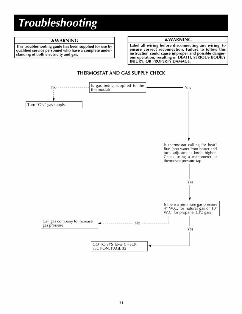
31
Troubleshooting
THERMOSTAT AND GAS SUPPLY CHECK
Is thermostat calling for heat?Run (hot) water from heater andturn adjustment knob higher.Check using a manometer atthermostat pressure tap.
Is there a minimum gas pressure4″ W.C. for natural gas or 10″W.C. for propane (L.P.) gas?
GO TO SYSTEMS CHECK SECTION, PAGE 32
Turn “ON” gas supply.
Call gas company to increasegas pressure.
Yes
Yes
YesNo Is gas being supplied to thethermostat?
No
WARNINGThis troubleshooting guide has been supplied for use byqualified service personnel who have a complete under-standing of both electricity and gas.
WARNINGLabel all wiring before disconnecting any wiring; toensure correct reconnection. Failure to follow thisinstruction could cause improper and possible danger-ous operation, resulting in DEATH, SERIOUS BODILYINJURY, OR PROPERTY DAMAGE.

32
Troubleshooting (cont’d)SYSTEMS CHECK
Please check guidelines below. For your safety, water heaterservice should be performed only by a qualified servicetechnician.
WARNINGDO NOT BY-PASS ANY CONTROLS TO MAKE HEATEROPERATE. OPERATE ONLY AS WIRED FROM FACTORY.
LED STATUS PROBLEM SOLUTION
An open earth ground circuit to the 1. Check that the earth ground connection isignition system. properly connected.
2. Check that the ground conductor on thewater heater is properly connected.
Wiring error or a high resistance to 1. Check for proper connection of line neutralearth ground. and hot wires.
2. Check that the water heater is securely connected to earth ground.
Pressure switch remained closed longer 1. Pressure switch wiring is incorrect.than 5 seconds after the call for heat 2. Replace pressure switch.began.
Pressure switch remained opened longer 1. Pressure switch wiring is incorrect.than 5 seconds after the combustion 2. Pressure switch tubing not connectedblower was energized. correctly.
3. Air intake or exhaust obstructed.
Error in the hot surface ignitor circuit. 1. Check that all wiring is correct and secure.2. Replace hot surface ignitor.
System in lockout. 1. Gas supply is off or too low to operate.2. Hot surface ignitor not positioned correctly.3. Low voltage to the water heater.4. Electric polarity to unit is incorrect - test
and correct.
Problem in the gas valve driver circuit. 1. Turn power to the water heater off for10 seconds and then back on.
2. Replace gas control valve.
Problem with the internal circuit. 1. Turn power to the water heater off for10 seconds and then back on.
2. Replace gas control valve.
Problem with the internal circuit. 1. Turn power to the water heater off for10 seconds and then back on.
2. Replace gas control valve.
Flame signal sensed out of proper 1. Replace gas control valve.sequence.
ECO activated. 1. Replace gas control valve.
One of the temperature adjust buttons 1. Press and release each of the buttons once.stuck closed. 2. Replace gas control valve.
Water temperature sensor is either 1. Check that all wiring is correct and secure.open or short circuited. 2. Replace gas control valve.
A B C
A B C
A B C
A B C
A B C
A B C
A B C
A B C
A B C
A B C
A B C
A B C
A B C
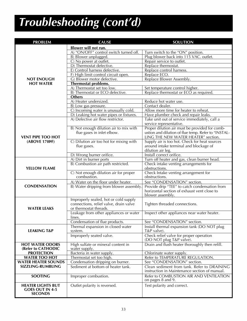
33
Troubleshooting (cont’d)
PROBLEM CAUSE SOLUTIONBlower will not run.A) “ON/OFF” control switch turned off. Turn switch to the “ON” position.B) Blower unplugged. Plug blower back into 115 VAC. outlet.C) No power at outlet. Repair service to outlet.D) Thermostat defective. Replace thermostat.E) Control harness defective. Replace control harness.F) High limit control circuit open. Replace ECO.
NOT ENOUGH G) Blower motor defective. Replace Blower Assembly.HOT WATER Thermostat problems.
A) Thermostat set too low. Set temperature control higher.B) Thermostat or ECO defective. Replace thermostat or ECO as required.OthersA) Heater undersized. Reduce hot water use.B) Low gas pressure. Contact dealer.C) Incoming water is unusually cold. Allow more time for heater to reheat.D) Leaking hot water pipes or fixtures. Have plumber check and repair leaks.A) Defective air flow restrictor. Take unit out of service immediately, call a
service representative.B) Not enough dilution air to mix with Proper dilution air must be provided for comb-
flue gases in inlet elbow. ustion and dilution of flue temp. Refer to “INSTAL-VENT PIPE TOO HOT LING THE NEW WATER HEATER” section.
(ABOVE 170ÞF) C) Dilution air too hot for mixing with Supply air is too hot. Check for heat sourcesflue gases. around intake terminal and blockage of
dilution air leg.D) Wrong burner orifice. Install correct orifice.A) Dirt in burner ports Turn off heater and gas, clean burner head.B) Combustion air path restricted. Check intake venting arrangements for
YELLOW FLAME obstructions.C) Not enough dilution air for proper Check Intake venting arrangement for
combustion. obstructions.A) Water on the floor under heater. See “CONDENSATION” section.
CONDENSATION B) Water dripping from blower assembly. Provide drip “TEE” to catch condensation from horizontal section of exhaust vent close to blower assembly.
Improperly sealed, hot or cold supplyconnections, relief valve, drain valve Tighten threaded connections.
WATER LEAKS or thermostat threads.Leakage from other appliances or water Inspect other appliances near water heater.lines.Condensation of flue products. See “CONDENSATION” section.Thermal expansion in closed water Install thermal expansion tank (DO NOT plug
LEAKING T&P system. T&P valve).Improperly seated valve. Check relief valve for proper operation
(DO NOT plug T&P valve).HOT WATER ODORS High sulfate or mineral content in Drain and flush heater thoroughly then refill.(Refer to CATHODIC water supply.
PROTECTION Bacteria in water supply. Chlorinate water supply.WATER TOO HOT Thermostat set too high. Refer to TEMPERATURE REGULATION.
WATER HEATER SOUNDS Condensation dripping on burner. See “CONDENSATION” section.SIZZLING-RUMBLING Sediment at bottom of heater tank. Clean sediment from tank. Refer to DRAINING
instruction in Maintenance section of manual.SOOTING Improper combustion. Refer to COMBUSTION AIR AND VENTILATION
on pages 8 and 9.HEATER LIGHTS BUT Outlet polarity is reversed. Test polarity and correct.
GOES OUT IN 4-5 SECONDS
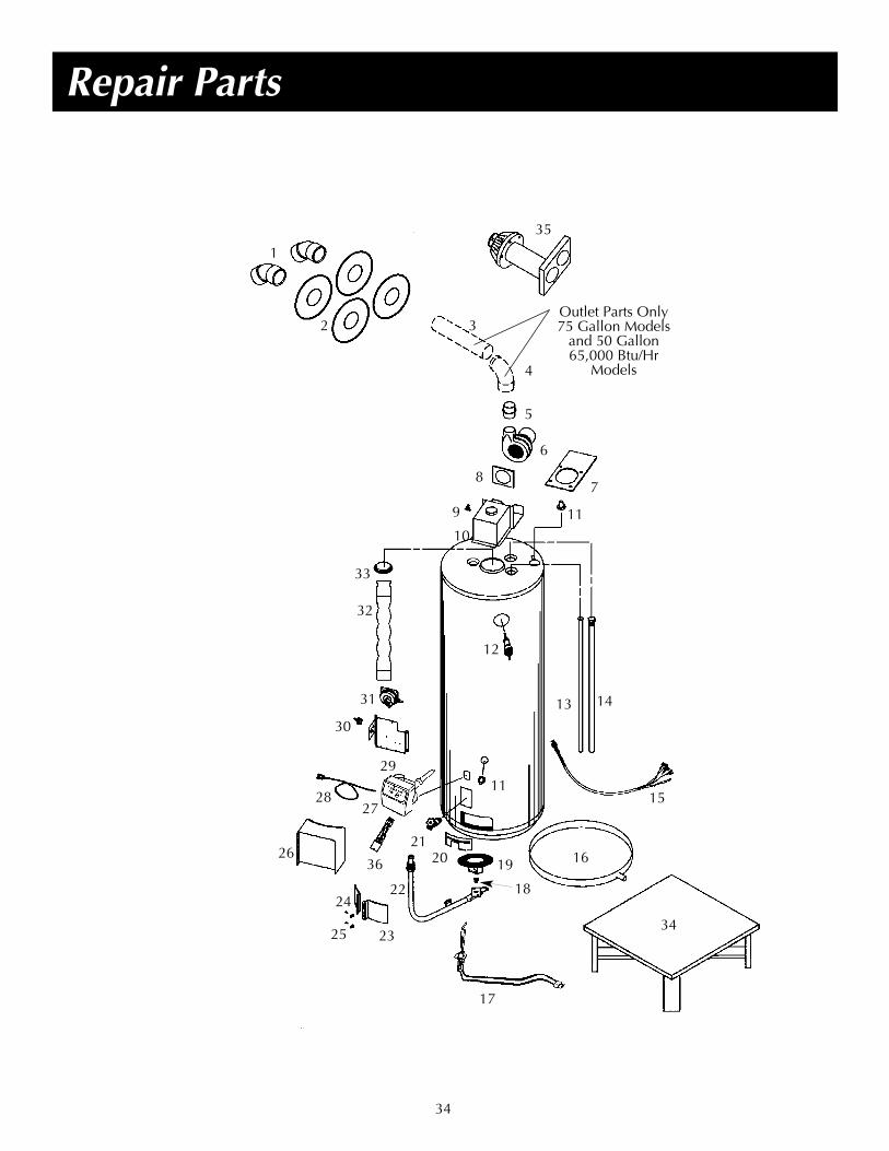
34
Repair Parts
119
10
32
31
30
20
8
18
21
28
7
24
17
22
16
34
11
12
15
26
33
23
6
25
14
29
27
19
13
5
Outlet Parts Only75 Gallon Models
and 50 Gallon 65,000 Btu/Hr
Models
3
1
2
35
4
36

KEY PARTNO. DESCRIPTION1. Vent Cap w/Screen2. Adaptor, Flue Mounting
3. 5′ ABS Schedule 40 Vent Pipe
4. 90° ABS Schedule 40Elbow
5. Vent/Blower Adapter6. Blower7. Flue Adaptor Gasket
(6″ x 10.102″)8. Blower Gasket9. Venting; Manual
Reset Switch10. Vent Hood Assembly11. Rubber Gasket – Wiring12. T&P Valve13. Dip Tube 14. Anode Rod15. Wiring Harness16. Drain Pan17. Hot Surface Ignition
Assembly18. Orifice (Natural)
Standard 18. Orifice (L.P.)
Standard 18. Orifice (Nat.)
High Altitude 18. Orifice (L.P.)
High Altitude
Repair Parts (cont’d)
Now that you have purchased this Water Heater, should a need ever exist for repair parts or service, simply contact the com-pany it was purchased from or the manufacturer listed on the model rating plate on the water heater.
Be sure to provide all pertinent facts when you call or visit.
Selling prices will be furnished on request or parts will be shipped at prevailing price and you will be billed accordingly.
The model number of your Gas Water Heater will be found on the model rating plate located above the gas control valve.
WHEN ORDERING REPAIR PARTS, ALWAYS GIVE THE FOLLOWING INFORMATION:MODEL NUMBER (TYPE GAS) NATURAL OR PROPANE (L.P.)SERIAL NUMBER PART DESCRIPTION
PART NUMBER
THIS IS A REPAIR PARTS LIST, NOT A PACKING LIST.
35
KEY PARTNO. DESCRIPTION19. Burner Assembly (Nat.)19. Burner Assembly (L.P.)20. Inner Door21. Drain Valve22. Manifold (Natural)22. Manifold (L.P.)23. Right Access Door
w/Gasket24. Left Access Door
w/Gasket25A. Access Door Clips (2)25B. Jacket/Access
Door Clips (8)26. Pressure Switch (Air) Cover27. Gas Thermostat (Nat.)27. Gas Thermostat (L.P.)28. Power Cord29. Mounting Bracket30. On/Off Switch31. Pressure Switch (Air)32. Flue Baffle Assembly33. Baffle Adaptor
Collar Assembly34. Water Heater Stand35. Optional (Deluxe)
Horizontal Vent Kit36. 4 to 5 pin adapter