Research Article Shifting Control Algorithm for a Single...
12
Research Article Shifting Control Algorithm for a Single-Axle Parallel Plug-In Hybrid Electric Bus Equipped with EMT Yunyun Yang, Sen Wu, and Xiang Fu Hubei Key Laboratory of Advanced Technology of Automobile Parts, School of Automotive Engineering, Wuhan University of Technology, Wuhan 430070, China Correspondence should be addressed to Yunyun Yang; [email protected] Received 23 September 2014; Accepted 24 November 2014; Published 21 December 2014 Academic Editor: Muhammad Naveed Iqbal Copyright © 2014 Yunyun Yang et al. is is an open access article distributed under the Creative Commons Attribution License, which permits unrestricted use, distribution, and reproduction in any medium, provided the original work is properly cited. Combining the characteristics of motor with fast response speed, an electric-drive automated mechanical transmission (EMT) is proposed as a novel type of transmission in this paper. Replacing the friction synchronization shiſting of automated manual transmission (AMT) in HEVs, the EMT can achieve active synchronization of speed shiſting. e dynamic model of a single-axle parallel PHEV equipped with the EMT is built up, and the dynamic properties of the gearshiſt process are also described. In addition, the control algorithm is developed to improve the shiſting quality of the PHEV equipped with the EMT in all its evaluation indexes. e key techniques of changing the driving force gradient in preshiſting and shiſting compensation phases as well as of predicting the meshing speed in the gear meshing phase are also proposed. Results of simulation, bench test, and real road test demonstrate that the proposed control algorithm can reduce the gearshiſt jerk and the power interruption time noticeably. 1. Introduction In the past few years, hybrid electric vehicles (HEVs) have demonstrated advantages in reducing the fuel consumption and pollution emissions [1–3]. Compared with conventional HEVs, plug-in hybrid electric vehicles (PHEVs) can recharge from an external source. Before the technology of pure electric vehicles (EV) becomes mature, PHEVs offer a feasible solution to the transportation in which part of the required petroleum resource is replaced with electricity [4]. e driveline system plays a crucial role in vehicle’s fuel- saving performance and driving comfort. Automated manual transmission (AMT) has been a decent candidate for the power transmission of heavy HEVs for its high efficiency, low cost, and high reliability. Besides, AMT can be modified in the conventional transmissions. However, AMT has still some drawbacks of power interruption and shiſting jerk in the gear shiſting process. Furthermore, the excessive wears of the clutch disc and synchronizer affect the application of AMT in HEVs [5–7]. Much research has been conducted to find better solutions to AMTs’ shortcomings in HEVs. For reducing the power interruption time, Baraszu and Cikanek [8] proposed that the vehicles should be directly driven by motor during the gear shiſting process in parallel HEVs equipped with AMT. Jo et al. [9] and Liao et al. [10] introduced a control strategy which controlled the torques and speeds of the engine and motor to reduce the synchronizing torque of AMTs’ synchronizer and clutch. So far few literatures on the gear shiſting control strategies without disengaging the clutch for HEVs equipped with AMT have been reported [5, 11, 12]. But those disadvantages of AMT could not be thoroughly avoided due to the slow response of engine. In order to solve these problems, we designed a new automatic transmission, namely, electric-drive automated mechanical transmission (EMT), which improved the struc- ture of AMT. By removing the synchronizer of AMT and adding the drive motor and the control system to it, the EMT was constructed. With the rapid response of the motor, it could control the speed and torque of the motor to achieve shiſting synchronization in gear shiſting process. us the acceleration steadiness and the degree of smoothness of the vehicle are achieved [13–17], and consequently the vehicle drivability is improved. In this paper, a gear shiſting control algorithm is designed for a single-axle parallel PHEV equipped with EMT. To do this, the dynamic properties of the gearshiſt process are Hindawi Publishing Corporation Discrete Dynamics in Nature and Society Volume 2014, Article ID 618587, 11 pages http://dx.doi.org/10.1155/2014/618587
Transcript of Research Article Shifting Control Algorithm for a Single...
Research ArticleShifting Control Algorithm for a Single-Axle ParallelPlug-In Hybrid Electric Bus Equipped with EMT
Yunyun Yang Sen Wu and Xiang Fu
Hubei Key Laboratory of Advanced Technology of Automobile Parts School of Automotive EngineeringWuhan University of Technology Wuhan 430070 China
Correspondence should be addressed to Yunyun Yang kristyyueng163com
Received 23 September 2014 Accepted 24 November 2014 Published 21 December 2014
Academic Editor Muhammad Naveed Iqbal
Copyright copy 2014 Yunyun Yang et al This is an open access article distributed under the Creative Commons Attribution Licensewhich permits unrestricted use distribution and reproduction in any medium provided the original work is properly cited
Combining the characteristics of motor with fast response speed an electric-drive automated mechanical transmission (EMT)is proposed as a novel type of transmission in this paper Replacing the friction synchronization shifting of automated manualtransmission (AMT) in HEVs the EMT can achieve active synchronization of speed shifting The dynamic model of a single-axleparallel PHEVequippedwith the EMT is built up and the dynamic properties of the gearshift process are also described In additionthe control algorithm is developed to improve the shifting quality of the PHEV equipped with the EMT in all its evaluation indexesThe key techniques of changing the driving force gradient in preshifting and shifting compensation phases as well as of predictingthe meshing speed in the gear meshing phase are also proposed Results of simulation bench test and real road test demonstratethat the proposed control algorithm can reduce the gearshift jerk and the power interruption time noticeably
1 Introduction
In the past few years hybrid electric vehicles (HEVs) havedemonstrated advantages in reducing the fuel consumptionand pollution emissions [1ndash3] Compared with conventionalHEVs plug-in hybrid electric vehicles (PHEVs) can rechargefrom an external source Before the technology of pureelectric vehicles (EV) becomesmature PHEVs offer a feasiblesolution to the transportation in which part of the requiredpetroleum resource is replaced with electricity [4]
The driveline system plays a crucial role in vehiclersquos fuel-saving performance and driving comfort Automatedmanualtransmission (AMT) has been a decent candidate for thepower transmission of heavyHEVs for its high efficiency lowcost and high reliability Besides AMT can be modified inthe conventional transmissionsHowever AMThas still somedrawbacks of power interruption and shifting jerk in thegear shifting process Furthermore the excessive wears of theclutch disc and synchronizer affect the application of AMT inHEVs [5ndash7]Much research has been conducted to find bettersolutions to AMTsrsquo shortcomings in HEVs For reducing thepower interruption time Baraszu and Cikanek [8] proposedthat the vehicles should be directly driven by motor during
the gear shifting process in parallel HEVs equipped withAMT Jo et al [9] and Liao et al [10] introduced a controlstrategy which controlled the torques and speeds of theengine and motor to reduce the synchronizing torque ofAMTsrsquo synchronizer and clutch So far few literatures on thegear shifting control strategies without disengaging the clutchfor HEVs equipped with AMT have been reported [5 11 12]But those disadvantages of AMT could not be thoroughlyavoided due to the slow response of engine
In order to solve these problems we designed a newautomatic transmission namely electric-drive automatedmechanical transmission (EMT) which improved the struc-ture of AMT By removing the synchronizer of AMT andadding the drive motor and the control system to it the EMTwas constructed With the rapid response of the motor itcould control the speed and torque of the motor to achieveshifting synchronization in gear shifting process Thus theacceleration steadiness and the degree of smoothness of thevehicle are achieved [13ndash17] and consequently the vehicledrivability is improved
In this paper a gear shifting control algorithm is designedfor a single-axle parallel PHEV equipped with EMT To dothis the dynamic properties of the gearshift process are
Hindawi Publishing CorporationDiscrete Dynamics in Nature and SocietyVolume 2014 Article ID 618587 11 pageshttpdxdoiorg1011552014618587
2 Discrete Dynamics in Nature and Society
Engine
EMT Battery
Motor controller
Vehicle controller
unit
Automaticclutch
Motor
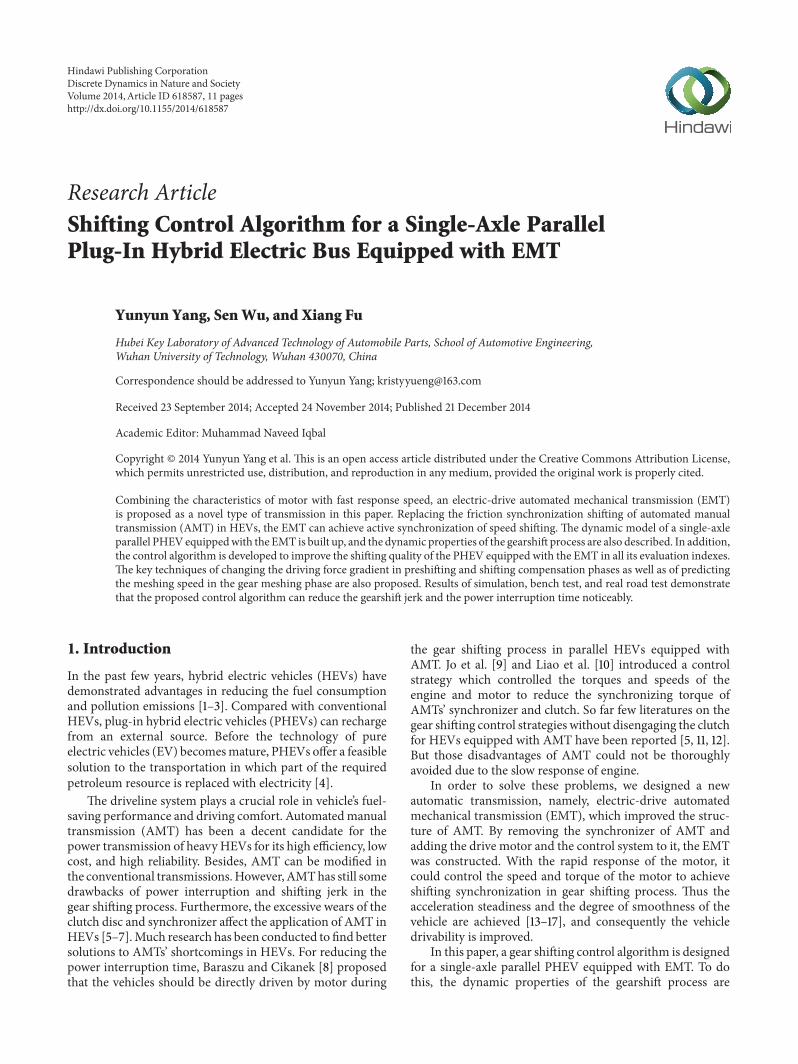
Figure 1 Structure diagram of a parallel PHEB powertrain with EMT
Motor
Z1Z3 Z5 Z7
Z8Z6
Z4Z2
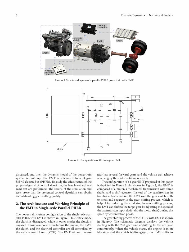
Figure 2 Configuration of the four-gear EMT
discussed and then the dynamic model of the powertrainsystem is built up The EMT is integrated to a plug-inhybrid electric bus (PHEB) To study the effectiveness of theproposed gearshift control algorithm the bench test and realroad test are performed The results of the simulation andtests prove that the presented control algorithm can obtainan outstanding gear shifting quality
2 The Architecture and Working Principle ofthe EMT in Single-Axle Parallel PHEB
The powertrain system configuration of the single-axle par-allel PHEB with EMT is shown in Figure 1 In electric modethe clutch is disengaged while in other modes the clutch isengaged Those components including the engine the EMTthe clutch and the electrical controller are all controlled bythe vehicle control unit (VCU) The EMT without reverse
gear has several forward gears and the vehicle can achievereversing by the motor rotating reversely
The configuration of a 4-gear EMTproposed in this paperis depicted in Figure 2 As shown in Figure 2 the EMT iscomposed of a motor a mechanical transmission with threeshafts and a shift actuator Instead of the synchronizer intraditional transmission the EMT uses the gear clutch teethto mesh and separate in the gear shifting process which ishelpful for reducing the axial size In gear shifting processthe EMT can shift to the target gear by adjusting the speed ofthe transmission input shaft (also the motor shaft) during thespeed synchronization phase
The gear shifting process of the PHEVwith EMT is shownin Figure 3 The schematic diagram displays the vehiclestarting with the 2nd gear and upshifting to the 4th gearcontinuously When the vehicle starts the engine is in anidle state and the clutch is disengaged the EMT shifts to
Discrete Dynamics in Nature and Society 3
Speed
Gear
Time
Idle
Clutch engageClutch engage
(II) Gear (III) Gear (IV) Gear
Engine speedTransmission output speed
Electrical machine speed
Figure 3 Gear shifting process of the PHEV with EMT
the 2nd gear and the vehicle runs in a pure electric modeAs the motor speed increases to the upshift point the EMTswitches to the 3rd gear After gear shifting the vehicle stillruns in the electric mode when the engine and the motorare controlled to have the same rotating speed the clutch isengaged The vehicle is driven solely by the motor during thewhole clutch engagement process After the clutch is engagedthe vehicle switches to the hybridmode (decided by thewholevehicle energy management strategy) When the speeds ofthe engine and the motor increase to the 3rd upshift pointthe clutch is separated and the transmission shifts off to theneutral gear and then the EMT starts to switch to the 4th gearwhich shares the same principle with the shift from the 2ndgear to the 3rd gear
3 Gear Shifting Quality Evaluation Indexes
Thegear shifting quality evaluation indexes of the PHEVwithEMT are power interruption time shifting jerk [18 19] andthe service life of the shifting components
31 Power Interruption Time The power interruption time119905PI refers to the time when vehicle is decelerating in the gearshifting process namely the time when the acceleration isnegative The gear shifting time of the single-axle parallelHEVwith EMT includes the time 119905
1of disengaging the clutch
the time 1199052of shifting-off to the neutral gear the time 119905
3of
motor active synchronization and the time 1199054of shifting on
the target gear Then the equation of the power interruptiontime can be expressed as
119905PI = max (1199051 1199052) + 1199053+ 1199054 (1)
32 Gear Shifting Jerk The gear shifting jerk is the changingrate of the vehiclersquos acceleration [20 21] it significantlyinfluences the drivability during the shifting process and canbe represented as
119895 =119889119886
119889119905=
119889
119889119905(119889V119889119905
) (2)
Start shiftingoperatingprocedure
Determine the target gearEnter the shifting mode
Start thepreshifting mode
Shift to the targetgear
Confirm the targetgear
End the shiftingmode and enter the
driving mode
Start shiftingcompensation
procedure
No
No
1
2
3
4
5
Figure 4 Flow diagram of the gearshift process for the PHEVequipped with EMT
where V is the vehicle velocity 119886 is the vehicle longitudinalacceleration
4 Control Algorithm Analyses forEMT Shifting
For obtaining excellent gear shifting quality an optimalcontrol algorithm is critical When the vehicle is not in gearshifting process the motor and engine are controlled by theVCU according to the vehicle control strategies and can berepresented as follows
119879119890= 119891 (120572
119890 119899119890)
119879119898= 119879req minus 119879
119890
(3)
where120572119890is the engine throttle opening 119899
119890is the engine speed
119879req is the vehicle demand torque 119879119890is the output torque of
the engine and 119879119898is the output torque of the motor
The gear shifting process of the single-axial parallel PHEVwith EMT is shown in Figure 4 When the target gear isdetermined by the input conditions the EMT switches to theshifting mode (step A in Figure 4) The process starts withthe preshifting procedure (step B in Figure 4) determinedby the torque request of the vehicle which can make thevehicle transit to the shifting operating procedure smoothlyThen the EMT evaluates the target gear in real time accordingto the road condition and driverrsquos physical conditionbecausethe preshifting phase has no power interruption (step Cin Figure 4) When the target gear is confirmed the EMTswitches to the gear shifting operation procedure (the keyof gearshift process) After shifting to the target gear theEMT starts the shifting compensation procedure (step Din Figure 4) which compensates the torque request for thevehicle With the finish of the phase D the shifting modeends and is followed by the driver operating mode (step Ein Figure 4) In the synthesis the gear shifting process ina single-axle parallel PHEV with EMT is divided into five
4 Discrete Dynamics in Nature and Society
processes forming the whole power process of driving andshifting The concrete analysis of the gear shifting processesB C D will be done below
41 Preshifting Process When the vehicle needs to shift to thenew gear which is determined by the VCU the powertrainswitches to the shifting mode and starts the preshifting pro-gram The system breaks off the shifting program only whenthe brake pedal is stamped by the driver And then the systemresponds to the control strategies of the vehicle and gearshifting otherwise the system switches to the shifting processsmoothly The main function of the preshifting program is toweaken the negative effects of the power interruption in theshifting process
When the vehicle is running on a flat road the drivingforce can be expressed as
119865119905= 119865119891+ 119865119908+ 119865119895 (4)
where 119865119905is the driving force 119865
119891is the rolling resistance
119865119908is the air resistance and 119865
119895is the acceleration resistance
which is related to the accelerationThe equation of 119865119895can be
expressed as follows
119865119895= 1205751119898
119889119906
119889119905 (5)
where119898 is the gross vehicle weight and 1205751is the rotary mass
coefficient of the vehicle in this process The equation of theshifting jerk can be represented as
119895 =1198892119906
1198891199052=
119889 (119865119895120575119898)
119889119905=
119889 (119865119905minus 119865119891minus 119865119908)
120575119898119889119905 (6)
According to the shifting requirements the shifting jerkmust meet the following condition
119895 le 119895max (7)
where 119895max is the reference value of the maximum gearshifting jerk The recommended values are 3163ms3 informer Soviet Union and 10ms3 in Germany
To avoid the power interruption in the preshifting phaseand to minimize the shifting jerk of the switching to neutralgear in the shifting process the vehicle acceleration in the endof the preshifting phase should approach zero and thus theequation can be written as follows
1198651199081
+ 1198651198911
minus 1198651199051
= 0 (8)
where 1198651199081 1198651198911 and 119865
1199051are the air resistance the rolling
resistance and the driving force in the end of the preshiftingphase
Then the equation of average jerk 119895119886is
119895119886=
(1198651199051minus 1198651199081
minus 1198651198911) minus (119865
1199050minus 1198651199080
minus 1198651198910)
1205751119898Δ11990501
=
1198651199080
+ 1198651198910
minus 1198651199050
1205751119898Δ11990501
le 119895max
(9)
where 1198651199080 1198651198910 and 119865
1199050are the air resistance the rolling
resistance and the driving force in the beginning of thepreshifting phase andΔ119905
01is the time of the preshifting phase
From (8) and (9) we can get
1198651199050
Δ11990501
ge
1198651199080
+ 1198651198910
Δ11990501
minus 1205751119898119895max (10)
The shifting jerk of the preshifting process can be ensuredto meet (7) by controlling the driving force gradient (119889119865
119905119889119905)
with the following requirement
119889119865119905
119889119905ge
1198651199080
+ 1198651198910
Δ11990501
minus 1205751119898119895max (11)
In the preshifting phase the output torque of the powersource (decided by the vehicle control strategies) is controlledby the control strategy of the driving force gradient
42 Shifting Operation Process The shifting operation pro-cess has three phases shifting-off phase motor active speedsynchronization phase and shifting compensation phaseThefollowing actions will be performed to realize the shifting
(a) Disengage the clutch in the shortest time accordingto the indexes of the shifting jerk and the powerinterruption time meanwhile the motor switches tothe idle mode with no torque output and the engineswitches to the idle mode Then the transmissionswitches to the neutral gear
(b) In order to realize the speed synchronization of theinput and output shafts the motor adjusts the speedin torque control mode meanwhile the target speedof the motor is calculated
(c) The transmission switches to the target gear when itmeets the shifting requirements
421 Shifting-Off Phase In this phase the clutch starts toseparate and the transmission switches to the neutral gearThe average jerk of this phase can be represented as
1198951198861
=
((1198651199052minus 1198651199082
minus 11986511989121205752119898) minus (119865
1199051minus 1198651199081
minus 11986511989111205751119898))
Δ11990512
(12)
where 1198651199082 1198651198912 and 119865
1199052are the air resistance the rolling
resistance and the driving force in the end of the shifting-off phase Δ119905
12is the time of the shifting-off phase and 119895
1198861is
the average jerk of this phaseIn the gearshift process we may consider that the vehicle
acceleration is approximately equal to zero so it is easy toshift off without excessive wear on the gears surfaces Thenthe rolling resistance and the air resistance keep unchangedThe average jerk can also be represented as
1198951198861
=
minus (1198651199082
+ 1198651198912)
1205752119898Δ11990512
=
minus (1198651199081
+ 1198651198911)
1205751119898Δ11990512
=
minus (1198651199080
+ 1198651198910)
1205751119898Δ11990512
(13)
Discrete Dynamics in Nature and Society 5
1205962A 1205962B1205961A 1205961B 1205962C 1205961C
A B C
Figure 5 The movement positions of the shift sleeve in shifting process
422 Motor Active Speed Synchronization Phase Afterswitching to the neutral gear start to reduce the speeddifference between the shift sleeve and shift gear of the targetgear which is called motor active speed synchronizationphase
The sketch of the movement positions of the shift sleeveteeth in shifting process is shown in Figure 5 The red teethrepresent the teeth of the shift sleeve while the blue onesrepresent those ofthe shift gear 119860 stands for the end of theactive synchronization phase and 119861 stands for the beginningof the gearmeshing119862 stands for the end of the gearmeshing1205961119860 1205961119861 and 120596
1119862represent the rotating speed of the shift
sleeve in stages 119860 119861 and 119862 respectively 1205962119860 1205962119861 and 120596
2119862
represent the speed of theshift gear in stages 119860 119861 and 119862respectively
The speeds of the input shaft and the output shaft shouldbe predicted in the process from 119860 to 119861 which is the idlemotion process of the shift sleeve The ideal condition of 119861is
1205961119861
= 1205962119861 (14)
In the active speed synchronization phase the speedvariation trends of the shift sleeve and shift gear should bepredicted accurately By theoretical analysis this paper adoptsthemean evaluationmethod to predict the target speed of thespeed regulation The equations of this phase are as follows
1205961119861
= 1205961119860
+ 1198861sdot 119905119860minus119861
1205962119861
= 1205962119860
+ 1198862sdot 119905119860minus119861
1205961119860
+ 1198861sdot 119905119860minus119861
= 1205962119860
+ 1198862sdot 119905119860minus119861
(15)
where 1198861is the acceleration of the shiftsleeve 119886
2is the
acceleration of the gear shaft and 119905119860minus119861
is the time from 119860 to119861
The speed of shift sleeveis measured by the speed sensorof the output shaft while the speed of gear shaft is measuredby the speed sensor of the motor 119886
1is calculated by the
relationship between the speed of the output shaft and thespeed regulation time At the end of the active synchroniza-tion phase the acceleration of themotor cannot bemeasuredso the acceleration of the gear shaft 119886
2cannot be obtained
either Through numerous experiments the value of 1205962119861
canbe predicted as follows
1205962119860
+ 1198862sdot 119905119860minus119861
= 119896119901sdot 1205962119860 (16)
where 119896119901is the proportionality coefficient which is related
to the speed and the output torque of the motor In practical
1
2
3
4
1205962 1205961
Figure 6 Position relationships between the teeth of shift sleeve andthose of shift gear
applications the parameter compensations are added to theoutput shaft acceleration 119886
1which is replaced with the weight
value Σ1198861 The equation of the weight value Σ119886
1can be
expressed as
Σ1198861= 1198961198861+ (1 minus 119896) 119886
119886 (17)
where 119896 is the weight coefficient which is related to the vehiclespeed in the beginning of the active synchronization and 119886
119886is
the average speed of shift sleeve in the active synchronizationThen 120596
2119860can be controlled as the following equation
1205962119860
=(1205961119860
+ Σ1198861sdot 119905119860minus119861
)
119896119901
(18)
423 Gear Meshing Phase In this phase the teeth of shiftsleeve and those of shift gear begin to mesh As shownin Figure 6 there are four different position relationshipsbetween the teeth of shift sleeve and those of shift gear inthe gear meshing phase The stages 2 and 4 are both specialsituations representing small probability events while thestages 1 and 3 appear in most cases Although the causes of
6 Discrete Dynamics in Nature and Society
Gear clutching tooth
Gear clutching tooth
120573
1205732 Ft2
FN
Ft1
Ft
FR
Fa998400
Fa998400998400 ds
1205732
Figure 7 The acting forces applied on the tooth of shift sleeve and those on the shift gear
stages 1 and 3 are different they have the same force situationTake stage 1 for example to analyze the force of the meshingteeth at the contact moment
The acting forces applied on the tooth of shift sleeve andthose on the shift gear are shown in Figure 7 The equationsof the forces can be expressed as follows
119872119904= 119865119905times
119889119904
2 (19)
119865119905= 1198651199051minus 1198651199052 (20)
119865119877= 119906119904times 119865119873 (21)
119865119886= 11986511988610158401015840 + 1198651198861015840 (22)
119865119905= 119865119873(cos
120573
2minus 119906119904times sin
120573
2) (23)
119865119886= 119865119873(sin
120573
2+ 119906119904times cos
120573
2) (24)
119865119873
=119865119886
sin (1205732) + 119906119904times cos (1205732)
(25)
119865119905= 119865119886
(cos (1205732) minus 119906119904times sin (1205732))
(sin (1205732) + 119906119904times cos (1205732))
(26)
119872119904= 119865119886times
119889119904(cos (1205732) minus 119906
119904times sin (1205732))
2 (sin (1205732) + 119906119904times cos (1205732))
(27)
119872119896= 119869119905sdot1198891205962
119889119905 (28)
where 119872119904is the blocking torque 119865
119905is the tangential (along
circumferential direction) force component 119865119877is the fric-
tional force 119865119873
is the normal force 119865119886is the axial shift
force 119889119886is the mean effective diameter of the shift gear 120573
is the angle of roof shape of the shift gear tooth 119906119904is the
static friction coefficient of gearrsquos meshing surface 119872119896is the
moment of inertia 119869119905is the equivalent rotational inertia of
jackshaft and the gears thereon and1205962is the rotational speed
of the shift gear
The axial force 119865119896is generated by the moment of inertia
119872119896which can be expressed as
119865119896=
119872119896
1198891199042
cot120573 (29)
The teeth of shift sleeve and those of shift gear canmesh without failure when the following two conditions aresatisfied (1) 119865
119896lt 119865119886 (2)119872
119896lt 119872119886
To simplify the modeling the static friction coefficient 119906119904
is assumed to be zero so (27) can be simplified as follows
119872119904= 119865119886times
119889119904
2cot
120573
2 (30)
As119872119896lt 119872119886 we can get
119865119886gt
119869
1198891199042
sdot119889120596
119889119905tan
120573
2 (31)
In this phase the shifting jerk 1198953can be represented as
1198953=
119889
119889119905(119889119906
119889119905) =
119889
119889119905(
1198940120578
1205753119898119903
119872119896) =
1198940120578
1205753119898119903
119889119872119896
119889119905le 119895max
(32)
where 119898 is the gross vehicle weight 1205753is the rotary mass
coefficient of the vehicle in the target gear 120578 is themechanicalefficiency of transmission system and 119894
0is themain reduction
ratioThe maximum shifting jerk occurs at the moment when
the teeth of shift gear contact those of the shift sleeveAccording to (32) we know that the gear shifting jerk isconnected with the change of the synthetic speed difference
43 Shifting Compensation Phase After shifting the outputtorque of the motor is restored and the vehicle is driven bythe motor In this phase the same control algorithm as thatin the preshifting process is used to restore the output torqueof the motor The driving force gradient (119889119865
119905119889119905) equation is
expressed as
119889119865119905
119889119905=
1198651199055
11990545
le 119895max sdot 1205753119898 (33)
Discrete Dynamics in Nature and Society 7
Figure 8 The EMT gear shifting process simulation
Table 1 Simulation results of shifting quality with different motor torques
Torque of the motorspeed adjustment
Shifting-offtimems
Motor activesynchronization
timems
Gear meshingtimems
Power interruptiontimems Shifting jerkms3
1199052
1199053
1199054
119905 119869
40 150 625 75 850 6960 150 400 75 625 7880 150 325 75 550 82100 150 250 75 475 96150 125 200 150 475 156
where 1198651199055
is the air resistance in the end of the shiftingcompensation phase and Δ119905
45is the time of this phase
In hybrid mode and engine mode the clutch is engagedafter this phase Then the vehicle comes back to the drivingmode which is controlled by the vehicle control strategies
5 Simulation Analysis
The gear shifting process of the hybrid electric drivetrainsystem is a sophisticated multi-rigid-body control systemwith complicated physical properties So it is difficult to getthe accurate shifting performance Then let us analyze thecontrol algorithm proposed above with the virtual prototypetechnology The EMT model is simulated on the softwareADAMS (Automatic Dynamic Analysis of Mechanical Sys-tems) For simplifying the simulation model the 4-speedEMT is replaced with a 2-speed EMT mode as shown inFigure 8
The simulation results of the speed and the shifting forkdisplacement response in the upshift process are shown inFigure 9 The EMT shifting control algorithm can satisfacto-rilymeet the gearshift requirements In the process of shiftingfrom the 1st to the 2nd gear and when the speed of the input
Input shaftOutput shaft
Shifting fork
300
350
400
450
500
550
600
00 10 20 30 40 50 60
Leng
th (m
m)
Ang
ular
velo
city
(deg
s)
Time (s)
00minus10000
100002000030000400005000060000700008000090000
Trr
Analysis Last Run
Figure 9 Simulation results of EMT shifting process
shaft is adjusted to approach the output shaft speed theshifting fork starts moving and the transmission shifts to the2nd gear During the whole gear shifting process the speedfluctuation of each shaft is small and so is the shifting jerk
By optimizing the simulation parameters we can getvarious shifting results of different motor torques in speedsynchronization phase as shown in Table 1 the sampling
8 Discrete Dynamics in Nature and Society
EMTControlalgorithm
Accelerator pedal signal
Brake pedal signal
Motor torque
Shift force
Shifting fork positionMotor speed
Speed of transmission output shaft
Figure 10 The diagram of the shifting process control model
Figure 11 The test bench
frequency is 25ms The power interruption time is no morethan 085 s We can also notice that the greater the torque ofthemotor regulating speed is the shorter the power interrupttime is and also the shorter the power interrupt time isthe greater the shifting jerk will be When the torque of theregulating speed is below the 100 the power interruptiontime reduces with the increase of it while when the torqueof the regulating speed is over 100 the power interruptiontime change is small This is due to the fact that with theincrease of the torque of the motor speed adjustment thegear meshing time is longer despite the fact that the shifting-off time and motor active synchronization time are shorterAccording to the simulation results we also know that withthe shifting control algorithm the shifting jerk has beendecreased and the shifting quality has been improved
6 Bench Test and Road Test
To verify the control algorithm for shifting a single-axleparallel PHEB equipped with EMT the bench test and roadtest were conducted respectively The vehicle parameters areshown inTable 2The shifting process controlmodel is shownin Figure 10 The test bench picture is shown in Figure 11
The control system of the dynamometer can display theoutput torque and speed of power sources in real time and theshifting jerk of output shaft can be calculated simultaneouslyThe test results of the continuous upshift and downshiftprocesses performed with the EMT in the bench test areshown in Figure 12 For analyzing the control algorithm thetest results of the output shaft speed and the input shaft speedare shown in Figure 13 withmarks As shown in Figure 13 the
Table 2 The powertrain and vehicle parameters of the PHEB
Parameters ValueCurb weightfull load gross masskg 1300018000Main reducer ratio 62Transmission ration (4-gear) 582 323 179 1Engine displacementL 298Maximum power (kW)speed (rpm) 953200Maximum torque (Nm)speed (rpm) 3451600sim2400Motor Induction motorRatedpeak power (kW) 80160Maximum torque (Nsdotm) 954Lithium ion batteryCapacitor (Ah)rated voltage (V) 160576
Table 3 The statistical data of the gearshift quality
Gear change 1199052s 119905
3s 119905
4s 119905PIs
Maximumshifting jerk
ms3
1rarr 2 012 053 011 076 522rarr 3 010 061 010 081 813rarr 4 009 064 012 085 864rarr 3 009 046 010 065 minus39
3rarr 2 009 050 014 073 minus32
2rarr 1 010 045 013 068 minus47
phases of BC (1st to 2nd) DE (2nd to 3rd) and FG (3rd to 4th)are the upshift processes while those of IJ (4th to 3rd) KL(3rd to 2nd) andMN (2nd to 1st) are the downshift processes
The bench test results of shifting jerk are shown inFigure 14The results of power interrupting time and shiftingjerk of each gear are shown in Table 3 As can be seen fromthe Table the power interrupt time is controlledwithin 085 sand the shifting jerk is controlled within 86ms3 The motoractive synchronization phase takes about 70 of the powerinterrupt time which is impacted by the torque of the motorspeed adjustment
After plenty of bench tests the road tests with a 12mPHEV equipped with the EMT were conducted The pictureof the PHEB is shown in Figure 15 According to the controlstrategies the test results of the engine speed gear positionsensor signals clutch position sensor signals motor speed
Discrete Dynamics in Nature and Society 9
Input shaft speed Output shaft speedShifting fork positionof the 1st and 2ndgear
Shifting fork positionof the 3rd and 4thgear
0
1
2
3
4
5
0
500
1000
1500
2000
2500
3000
0 200 400 600 800 1000 1200 1400 1600 1800 2000
Disp
lace
men
t (m
m)
Spee
d (r
pm)
Time (times25 ms)
Figure 12 Test results of shifting process
A0
500
1000
1500
2000
2500
3000
1
124
247
370
493
616
739
862
985
1108
1231
1354
1477
1600
1723
1846
1969
Spee
d (r
pm)
Input shaft speedOutput shaft speed
B
C
D
E
F
G
H
IJ
K
L
MN
O
P
Time (times25 ms)
B1 E1
F1
F2
F3B3
B2
C1
D2
D3D1
J1 K1
L 1
M1
O1
O2
P1
N1
Figure 13 Test results of shifting with marks
output shaft speed and speed ratios are shown in Figure 16The curves show the test processes in which the PHEB wasstarting with the 2nd gear and accelerating to the 4th gearand then decelerating and downshifting to the 2nd gear Thepower interrupt time of the PHEB is less than 08 s andthe speed of the output shaft changes smoothly The shiftingjerk is no more than 10ms3 which meets the recommendedreference value of the shifting jerk in Germany
7 Conclusions
In this paper the working principle of a single-axle parallelPHEV equipped with an EMT is described and analysis ofthe shifting dynamics model in each transient process is alsogiven in detail Moreover a new shifting control algorithmis introduced for improving the gearshift quality withoutsynchronizer With the control algorithm the gears of thesingle-axle parallel PHEV equipped with the EMT can becontrolled to engage faster and successfully without excessivewear on the gear surfaces It is also important to note thatthe control algorithm was verified on a simulation platformby the bench test and PHEB test All the results prove thatadopting this control algorithm in parallel PHEV equippedwith the EMT can improve the shifting quality significantly
1 21 41 61 81 101 121
1st gear shift to 2nd gear10
0
minus10Shift
ing
jerk
(ms3)
Time (times25 ms)
The end of the shift
1 21 41 61
2nd gear shift to 3rd gear
Shift
ing
jerk
(ms3)
10
0
minus10
minus20Time (times25 ms)
The end of the shift
1 21 41
3rd gear shift to 4th gear25
15
5
minus5
minus15
minus25
minus35
Shift
ing
jerk
(ms3)
Time (times25 ms)
The end of the shift
1 21 41 61 81 101 121
10
0
minus10
Shift
ing
jerk
(ms3)
Time (times25 ms)The end of the shift
1 21 41 61 81
3rd gear shift to 2nd gear10
0
minus10Shift
ing
jerk
(ms3)
Time (times25 ms) The end of the shift
1 21 41 61 81 101 121 141 161
2nd gear shift to 1st gear10
0
minus10
Shift
ing
jerk
(ms3)
Time (times25 ms) The end of the shift
4th gear shift to 3rd gear
Figure 14 The test results of shifting jerk
Figure 15 The test PHEB with EMT
through its evaluation indexes which is likely to help toreplace the traditional AMT in HEV
The EMT with proposed shifting control algorithm canalso be applied to EVs and other kinds of HEVs to improvethe shifting quality In the near future further study on EMT
10 Discrete Dynamics in Nature and Society
5250
5260
5280
5270
5290
5300
5310
5320
5330
5340
5350
5360
5370
5380
5390
Time (s)
60
50
40
30
20
10
0
MG
ear
Posit
ion
(val
ue)
2500
2000
1500
1000
500
0
minus500Sp
eed
(rpm
)
20000
0
minus20000
minus40000
minus60000
minus80000
minus100000
MG
ear
Posit
ion
(val
ue)
160000
140000
120000
100000
80000
60000
40000
20000
0
minus20000
AIG
earP
osio
tion2
(val
ue)
180000
160000
140000
120000
100000
80000
60000
40000
20000
0
AIG
ear
Posit
ion1
(val
ue)
Engine speedMotor speed
S speed
Figure 16 Road test curves of the gear shifting
shiftingwill be carried on and the new shifting algorithmwillbe proposed to improve the shifting quality further
Conflict of Interests
The authors declare that there is no conflict of interestsregarding the publication of this paper
Acknowledgment
This work was supported by the National High TechnologyResearch and Development Program of China (Grant no2011AA11A260)
References
[1] I M C Uygan A E Hartavi L Guvenc V Sezer andT Acarman ldquoPropulsion system design of a hybrid electricvehiclerdquo International Journal of Vehicle Design vol 52 no 1ndash4 pp 96ndash118 2010
[2] T Sousa H Morais Z Vale P Faria and J Soares ldquoIntelligentenergy resource management considering vehicle-to-grid asimulated annealing approachrdquo IEEE Transactions on SmartGrid vol 3 no 1 pp 535ndash542 2012
[3] A Y Saber and G K Venayagamoorthy ldquoPlug-in vehicles andrenewable energy sources for cost and emission reductionsrdquoIEEE Transactions on Industrial Electronics vol 58 no 4 pp1229ndash1238 2011
[4] J Tollefson ldquoCar industry charging up the futurerdquo Nature vol456 pp 436ndash440 2008
[5] Z Zhong G Kong Z Yu X Xin andX Chen ldquoShifting controlof an automated mechanical transmission without using theclutchrdquo International Journal of Automotive Technology vol 13no 3 pp 487ndash496 2012
[6] H Yu J Xi F Zhang and Y Hu ldquoResearch on gear shiftingprocess without disengaging clutch for a parallel hybrid electric
vehicle equipped with AMTrdquo Mathematical Problems in Engi-neering vol 2014 Article ID 985652 12 pages 2014
[7] L Glielmo L Iannelli V Vacca and F Vasca ldquoGearshift controlfor automatedmanual transmissionsrdquo IEEEASMETransactionson Mechatronics vol 11 no 1 pp 17ndash26 2006
[8] R C Baraszu and S R Cikanek ldquoTorque fill-in for an auto-mated shift manual transmission in a parallel hybrid electricvehiclerdquo in Proceedings of the American Control Conference pp1431ndash1436 Anchorage Alaska USA May 2002
[9] H-S Jo Y-I Park J-M Lee H-D Lee and S-K SulldquoDevelopment of an advanced shift control algorithm for ahybrid vehicles with automated manual transmissionrdquo HeavyVehicle Systems vol 7 no 4 pp 281ndash298 2000
[10] C Liao J Zhang and Q Lu ldquoCoordinated powertrain con-trol method for shifting process of automated mechanicaltransmission in the hybrid electric vehiclerdquo Chinese Journal ofMechanical Engineering vol 41 no 12 pp 37ndash41 2005
[11] X T Lu and G Z Hou ldquoIntroduction of the AMT controlsystem structure and main foreign AMT productsrdquo AutomobileTechnology vol 5 pp 19ndash22 2004 (Chinese)
[12] HHe Z Liu L Zhu andX Liu ldquoDynamic coordinated shiftingcontrol of automatedmechanical transmissionswithout a clutchin a plug-in hybrid electric vehiclerdquo Energies vol 5 no 8 pp3094ndash3109 2012
[13] MMontazeri-Gh andMAsadi ldquoIntelligent approach for paral-lel HEV control strategy based on driving cyclesrdquo InternationalJournal of Systems Science vol 42 no 2 pp 287ndash302 2011
[14] L Glielmo L Iannelli V Vacca and F Vasca ldquoGearshift controlfor automatedmanual transmissionsrdquo IEEEASMETransactionson Mechatronics vol 11 no 1 pp 17ndash26 2006
[15] M Pettersson and L Nielsen ldquoGear shifting by engine controlrdquoIEEE Transactions on Control Systems Technology vol 8 no 3pp 495ndash507 2000
[16] C Chen and T T Liang ldquoTheoretic study of efficiency of two-DOFs of epicyclic gear transmission via virtual powerrdquo Journalof Mechanical Design Transactions of the ASME vol 133 no 3Article ID 031007 2011
Discrete Dynamics in Nature and Society 11
[17] J R G Ayats J V Calvet J M Canela U Diego-Ayala andF F Artes ldquoPower transmitted through a particular branch inmechanisms comprising planetary gear trains and other fixedor variable transmissionsrdquoMechanism andMachineTheory vol46 no 11 pp 1744ndash1754 2011
[18] B Mashadi A Kazemkhani and R Baghaei Lakeh ldquoAnautomatic gear-shifting strategy for manual transmissionsrdquoProceedings of the Institution of Mechanical Engineers I vol 221no 5 pp 757ndash768 2007
[19] S E Moon H S Kim and S H Hwang ldquoDevelopment ofautomatic clutch actuator for automatedmanual transmissionsrdquoInternational Journal of Automotive Technology vol 6 no 5 pp461ndash466 2005
[20] E Galvagno M Velardocchia and A Vigliani ldquoDynamic andkinematic model of a dual clutch transmissionrdquoMechanism andMachine Theory vol 46 no 6 pp 794ndash805 2011
[21] MKulkarni T Shim andY Zhang ldquoShift dynamics and controlof dual-clutch transmissionsrdquoMechanism and Machine Theoryvol 42 no 2 pp 168ndash182 2007
Submit your manuscripts athttpwwwhindawicom
Hindawi Publishing Corporationhttpwwwhindawicom Volume 2014
MathematicsJournal of
Hindawi Publishing Corporationhttpwwwhindawicom Volume 2014
Mathematical Problems in Engineering
Hindawi Publishing Corporationhttpwwwhindawicom
Differential EquationsInternational Journal of
Volume 2014
Applied MathematicsJournal of
Hindawi Publishing Corporationhttpwwwhindawicom Volume 2014
Probability and StatisticsHindawi Publishing Corporationhttpwwwhindawicom Volume 2014
Journal of
Hindawi Publishing Corporationhttpwwwhindawicom Volume 2014
Mathematical PhysicsAdvances in
Complex AnalysisJournal of
Hindawi Publishing Corporationhttpwwwhindawicom Volume 2014
OptimizationJournal of
Hindawi Publishing Corporationhttpwwwhindawicom Volume 2014
CombinatoricsHindawi Publishing Corporationhttpwwwhindawicom Volume 2014
International Journal of
Hindawi Publishing Corporationhttpwwwhindawicom Volume 2014
Operations ResearchAdvances in
Journal of
Hindawi Publishing Corporationhttpwwwhindawicom Volume 2014
Function Spaces
Abstract and Applied AnalysisHindawi Publishing Corporationhttpwwwhindawicom Volume 2014
International Journal of Mathematics and Mathematical Sciences
Hindawi Publishing Corporationhttpwwwhindawicom Volume 2014
The Scientific World JournalHindawi Publishing Corporation httpwwwhindawicom Volume 2014
Hindawi Publishing Corporationhttpwwwhindawicom Volume 2014
Algebra
Discrete Dynamics in Nature and Society
Hindawi Publishing Corporationhttpwwwhindawicom Volume 2014
Hindawi Publishing Corporationhttpwwwhindawicom Volume 2014
Decision SciencesAdvances in
Discrete MathematicsJournal of
Hindawi Publishing Corporationhttpwwwhindawicom
Volume 2014 Hindawi Publishing Corporationhttpwwwhindawicom Volume 2014
Stochastic AnalysisInternational Journal of
2 Discrete Dynamics in Nature and Society
Engine
EMT Battery
Motor controller
Vehicle controller
unit
Automaticclutch
Motor
Figure 1 Structure diagram of a parallel PHEB powertrain with EMT
Motor
Z1Z3 Z5 Z7
Z8Z6
Z4Z2
Figure 2 Configuration of the four-gear EMT
discussed and then the dynamic model of the powertrainsystem is built up The EMT is integrated to a plug-inhybrid electric bus (PHEB) To study the effectiveness of theproposed gearshift control algorithm the bench test and realroad test are performed The results of the simulation andtests prove that the presented control algorithm can obtainan outstanding gear shifting quality
2 The Architecture and Working Principle ofthe EMT in Single-Axle Parallel PHEB
The powertrain system configuration of the single-axle par-allel PHEB with EMT is shown in Figure 1 In electric modethe clutch is disengaged while in other modes the clutch isengaged Those components including the engine the EMTthe clutch and the electrical controller are all controlled bythe vehicle control unit (VCU) The EMT without reverse
gear has several forward gears and the vehicle can achievereversing by the motor rotating reversely
The configuration of a 4-gear EMTproposed in this paperis depicted in Figure 2 As shown in Figure 2 the EMT iscomposed of a motor a mechanical transmission with threeshafts and a shift actuator Instead of the synchronizer intraditional transmission the EMT uses the gear clutch teethto mesh and separate in the gear shifting process which ishelpful for reducing the axial size In gear shifting processthe EMT can shift to the target gear by adjusting the speed ofthe transmission input shaft (also the motor shaft) during thespeed synchronization phase
The gear shifting process of the PHEVwith EMT is shownin Figure 3 The schematic diagram displays the vehiclestarting with the 2nd gear and upshifting to the 4th gearcontinuously When the vehicle starts the engine is in anidle state and the clutch is disengaged the EMT shifts to
Discrete Dynamics in Nature and Society 3
Speed
Gear
Time
Idle
Clutch engageClutch engage
(II) Gear (III) Gear (IV) Gear
Engine speedTransmission output speed
Electrical machine speed
Figure 3 Gear shifting process of the PHEV with EMT
the 2nd gear and the vehicle runs in a pure electric modeAs the motor speed increases to the upshift point the EMTswitches to the 3rd gear After gear shifting the vehicle stillruns in the electric mode when the engine and the motorare controlled to have the same rotating speed the clutch isengaged The vehicle is driven solely by the motor during thewhole clutch engagement process After the clutch is engagedthe vehicle switches to the hybridmode (decided by thewholevehicle energy management strategy) When the speeds ofthe engine and the motor increase to the 3rd upshift pointthe clutch is separated and the transmission shifts off to theneutral gear and then the EMT starts to switch to the 4th gearwhich shares the same principle with the shift from the 2ndgear to the 3rd gear
3 Gear Shifting Quality Evaluation Indexes
Thegear shifting quality evaluation indexes of the PHEVwithEMT are power interruption time shifting jerk [18 19] andthe service life of the shifting components
31 Power Interruption Time The power interruption time119905PI refers to the time when vehicle is decelerating in the gearshifting process namely the time when the acceleration isnegative The gear shifting time of the single-axle parallelHEVwith EMT includes the time 119905
1of disengaging the clutch
the time 1199052of shifting-off to the neutral gear the time 119905
3of
motor active synchronization and the time 1199054of shifting on
the target gear Then the equation of the power interruptiontime can be expressed as
119905PI = max (1199051 1199052) + 1199053+ 1199054 (1)
32 Gear Shifting Jerk The gear shifting jerk is the changingrate of the vehiclersquos acceleration [20 21] it significantlyinfluences the drivability during the shifting process and canbe represented as
119895 =119889119886
119889119905=
119889
119889119905(119889V119889119905
) (2)
Start shiftingoperatingprocedure
Determine the target gearEnter the shifting mode
Start thepreshifting mode
Shift to the targetgear
Confirm the targetgear
End the shiftingmode and enter the
driving mode
Start shiftingcompensation
procedure
No
No
1
2
3
4
5
Figure 4 Flow diagram of the gearshift process for the PHEVequipped with EMT
where V is the vehicle velocity 119886 is the vehicle longitudinalacceleration
4 Control Algorithm Analyses forEMT Shifting
For obtaining excellent gear shifting quality an optimalcontrol algorithm is critical When the vehicle is not in gearshifting process the motor and engine are controlled by theVCU according to the vehicle control strategies and can berepresented as follows
119879119890= 119891 (120572
119890 119899119890)
119879119898= 119879req minus 119879
119890
(3)
where120572119890is the engine throttle opening 119899
119890is the engine speed
119879req is the vehicle demand torque 119879119890is the output torque of
the engine and 119879119898is the output torque of the motor
The gear shifting process of the single-axial parallel PHEVwith EMT is shown in Figure 4 When the target gear isdetermined by the input conditions the EMT switches to theshifting mode (step A in Figure 4) The process starts withthe preshifting procedure (step B in Figure 4) determinedby the torque request of the vehicle which can make thevehicle transit to the shifting operating procedure smoothlyThen the EMT evaluates the target gear in real time accordingto the road condition and driverrsquos physical conditionbecausethe preshifting phase has no power interruption (step Cin Figure 4) When the target gear is confirmed the EMTswitches to the gear shifting operation procedure (the keyof gearshift process) After shifting to the target gear theEMT starts the shifting compensation procedure (step Din Figure 4) which compensates the torque request for thevehicle With the finish of the phase D the shifting modeends and is followed by the driver operating mode (step Ein Figure 4) In the synthesis the gear shifting process ina single-axle parallel PHEV with EMT is divided into five
4 Discrete Dynamics in Nature and Society
processes forming the whole power process of driving andshifting The concrete analysis of the gear shifting processesB C D will be done below
41 Preshifting Process When the vehicle needs to shift to thenew gear which is determined by the VCU the powertrainswitches to the shifting mode and starts the preshifting pro-gram The system breaks off the shifting program only whenthe brake pedal is stamped by the driver And then the systemresponds to the control strategies of the vehicle and gearshifting otherwise the system switches to the shifting processsmoothly The main function of the preshifting program is toweaken the negative effects of the power interruption in theshifting process
When the vehicle is running on a flat road the drivingforce can be expressed as
119865119905= 119865119891+ 119865119908+ 119865119895 (4)
where 119865119905is the driving force 119865
119891is the rolling resistance
119865119908is the air resistance and 119865
119895is the acceleration resistance
which is related to the accelerationThe equation of 119865119895can be
expressed as follows
119865119895= 1205751119898
119889119906
119889119905 (5)
where119898 is the gross vehicle weight and 1205751is the rotary mass
coefficient of the vehicle in this process The equation of theshifting jerk can be represented as
119895 =1198892119906
1198891199052=
119889 (119865119895120575119898)
119889119905=
119889 (119865119905minus 119865119891minus 119865119908)
120575119898119889119905 (6)
According to the shifting requirements the shifting jerkmust meet the following condition
119895 le 119895max (7)
where 119895max is the reference value of the maximum gearshifting jerk The recommended values are 3163ms3 informer Soviet Union and 10ms3 in Germany
To avoid the power interruption in the preshifting phaseand to minimize the shifting jerk of the switching to neutralgear in the shifting process the vehicle acceleration in the endof the preshifting phase should approach zero and thus theequation can be written as follows
1198651199081
+ 1198651198911
minus 1198651199051
= 0 (8)
where 1198651199081 1198651198911 and 119865
1199051are the air resistance the rolling
resistance and the driving force in the end of the preshiftingphase
Then the equation of average jerk 119895119886is
119895119886=
(1198651199051minus 1198651199081
minus 1198651198911) minus (119865
1199050minus 1198651199080
minus 1198651198910)
1205751119898Δ11990501
=
1198651199080
+ 1198651198910
minus 1198651199050
1205751119898Δ11990501
le 119895max
(9)
where 1198651199080 1198651198910 and 119865
1199050are the air resistance the rolling
resistance and the driving force in the beginning of thepreshifting phase andΔ119905
01is the time of the preshifting phase
From (8) and (9) we can get
1198651199050
Δ11990501
ge
1198651199080
+ 1198651198910
Δ11990501
minus 1205751119898119895max (10)
The shifting jerk of the preshifting process can be ensuredto meet (7) by controlling the driving force gradient (119889119865
119905119889119905)
with the following requirement
119889119865119905
119889119905ge
1198651199080
+ 1198651198910
Δ11990501
minus 1205751119898119895max (11)
In the preshifting phase the output torque of the powersource (decided by the vehicle control strategies) is controlledby the control strategy of the driving force gradient
42 Shifting Operation Process The shifting operation pro-cess has three phases shifting-off phase motor active speedsynchronization phase and shifting compensation phaseThefollowing actions will be performed to realize the shifting
(a) Disengage the clutch in the shortest time accordingto the indexes of the shifting jerk and the powerinterruption time meanwhile the motor switches tothe idle mode with no torque output and the engineswitches to the idle mode Then the transmissionswitches to the neutral gear
(b) In order to realize the speed synchronization of theinput and output shafts the motor adjusts the speedin torque control mode meanwhile the target speedof the motor is calculated
(c) The transmission switches to the target gear when itmeets the shifting requirements
421 Shifting-Off Phase In this phase the clutch starts toseparate and the transmission switches to the neutral gearThe average jerk of this phase can be represented as
1198951198861
=
((1198651199052minus 1198651199082
minus 11986511989121205752119898) minus (119865
1199051minus 1198651199081
minus 11986511989111205751119898))
Δ11990512
(12)
where 1198651199082 1198651198912 and 119865
1199052are the air resistance the rolling
resistance and the driving force in the end of the shifting-off phase Δ119905
12is the time of the shifting-off phase and 119895
1198861is
the average jerk of this phaseIn the gearshift process we may consider that the vehicle
acceleration is approximately equal to zero so it is easy toshift off without excessive wear on the gears surfaces Thenthe rolling resistance and the air resistance keep unchangedThe average jerk can also be represented as
1198951198861
=
minus (1198651199082
+ 1198651198912)
1205752119898Δ11990512
=
minus (1198651199081
+ 1198651198911)
1205751119898Δ11990512
=
minus (1198651199080
+ 1198651198910)
1205751119898Δ11990512
(13)
Discrete Dynamics in Nature and Society 5
1205962A 1205962B1205961A 1205961B 1205962C 1205961C
A B C
Figure 5 The movement positions of the shift sleeve in shifting process
422 Motor Active Speed Synchronization Phase Afterswitching to the neutral gear start to reduce the speeddifference between the shift sleeve and shift gear of the targetgear which is called motor active speed synchronizationphase
The sketch of the movement positions of the shift sleeveteeth in shifting process is shown in Figure 5 The red teethrepresent the teeth of the shift sleeve while the blue onesrepresent those ofthe shift gear 119860 stands for the end of theactive synchronization phase and 119861 stands for the beginningof the gearmeshing119862 stands for the end of the gearmeshing1205961119860 1205961119861 and 120596
1119862represent the rotating speed of the shift
sleeve in stages 119860 119861 and 119862 respectively 1205962119860 1205962119861 and 120596
2119862
represent the speed of theshift gear in stages 119860 119861 and 119862respectively
The speeds of the input shaft and the output shaft shouldbe predicted in the process from 119860 to 119861 which is the idlemotion process of the shift sleeve The ideal condition of 119861is
1205961119861
= 1205962119861 (14)
In the active speed synchronization phase the speedvariation trends of the shift sleeve and shift gear should bepredicted accurately By theoretical analysis this paper adoptsthemean evaluationmethod to predict the target speed of thespeed regulation The equations of this phase are as follows
1205961119861
= 1205961119860
+ 1198861sdot 119905119860minus119861
1205962119861
= 1205962119860
+ 1198862sdot 119905119860minus119861
1205961119860
+ 1198861sdot 119905119860minus119861
= 1205962119860
+ 1198862sdot 119905119860minus119861
(15)
where 1198861is the acceleration of the shiftsleeve 119886
2is the
acceleration of the gear shaft and 119905119860minus119861
is the time from 119860 to119861
The speed of shift sleeveis measured by the speed sensorof the output shaft while the speed of gear shaft is measuredby the speed sensor of the motor 119886
1is calculated by the
relationship between the speed of the output shaft and thespeed regulation time At the end of the active synchroniza-tion phase the acceleration of themotor cannot bemeasuredso the acceleration of the gear shaft 119886
2cannot be obtained
either Through numerous experiments the value of 1205962119861
canbe predicted as follows
1205962119860
+ 1198862sdot 119905119860minus119861
= 119896119901sdot 1205962119860 (16)
where 119896119901is the proportionality coefficient which is related
to the speed and the output torque of the motor In practical
1
2
3
4
1205962 1205961
Figure 6 Position relationships between the teeth of shift sleeve andthose of shift gear
applications the parameter compensations are added to theoutput shaft acceleration 119886
1which is replaced with the weight
value Σ1198861 The equation of the weight value Σ119886
1can be
expressed as
Σ1198861= 1198961198861+ (1 minus 119896) 119886
119886 (17)
where 119896 is the weight coefficient which is related to the vehiclespeed in the beginning of the active synchronization and 119886
119886is
the average speed of shift sleeve in the active synchronizationThen 120596
2119860can be controlled as the following equation
1205962119860
=(1205961119860
+ Σ1198861sdot 119905119860minus119861
)
119896119901
(18)
423 Gear Meshing Phase In this phase the teeth of shiftsleeve and those of shift gear begin to mesh As shownin Figure 6 there are four different position relationshipsbetween the teeth of shift sleeve and those of shift gear inthe gear meshing phase The stages 2 and 4 are both specialsituations representing small probability events while thestages 1 and 3 appear in most cases Although the causes of
6 Discrete Dynamics in Nature and Society
Gear clutching tooth
Gear clutching tooth
120573
1205732 Ft2
FN
Ft1
Ft
FR
Fa998400
Fa998400998400 ds
1205732
Figure 7 The acting forces applied on the tooth of shift sleeve and those on the shift gear
stages 1 and 3 are different they have the same force situationTake stage 1 for example to analyze the force of the meshingteeth at the contact moment
The acting forces applied on the tooth of shift sleeve andthose on the shift gear are shown in Figure 7 The equationsof the forces can be expressed as follows
119872119904= 119865119905times
119889119904
2 (19)
119865119905= 1198651199051minus 1198651199052 (20)
119865119877= 119906119904times 119865119873 (21)
119865119886= 11986511988610158401015840 + 1198651198861015840 (22)
119865119905= 119865119873(cos
120573
2minus 119906119904times sin
120573
2) (23)
119865119886= 119865119873(sin
120573
2+ 119906119904times cos
120573
2) (24)
119865119873
=119865119886
sin (1205732) + 119906119904times cos (1205732)
(25)
119865119905= 119865119886
(cos (1205732) minus 119906119904times sin (1205732))
(sin (1205732) + 119906119904times cos (1205732))
(26)
119872119904= 119865119886times
119889119904(cos (1205732) minus 119906
119904times sin (1205732))
2 (sin (1205732) + 119906119904times cos (1205732))
(27)
119872119896= 119869119905sdot1198891205962
119889119905 (28)
where 119872119904is the blocking torque 119865
119905is the tangential (along
circumferential direction) force component 119865119877is the fric-
tional force 119865119873
is the normal force 119865119886is the axial shift
force 119889119886is the mean effective diameter of the shift gear 120573
is the angle of roof shape of the shift gear tooth 119906119904is the
static friction coefficient of gearrsquos meshing surface 119872119896is the
moment of inertia 119869119905is the equivalent rotational inertia of
jackshaft and the gears thereon and1205962is the rotational speed
of the shift gear
The axial force 119865119896is generated by the moment of inertia
119872119896which can be expressed as
119865119896=
119872119896
1198891199042
cot120573 (29)
The teeth of shift sleeve and those of shift gear canmesh without failure when the following two conditions aresatisfied (1) 119865
119896lt 119865119886 (2)119872
119896lt 119872119886
To simplify the modeling the static friction coefficient 119906119904
is assumed to be zero so (27) can be simplified as follows
119872119904= 119865119886times
119889119904
2cot
120573
2 (30)
As119872119896lt 119872119886 we can get
119865119886gt
119869
1198891199042
sdot119889120596
119889119905tan
120573
2 (31)
In this phase the shifting jerk 1198953can be represented as
1198953=
119889
119889119905(119889119906
119889119905) =
119889
119889119905(
1198940120578
1205753119898119903
119872119896) =
1198940120578
1205753119898119903
119889119872119896
119889119905le 119895max
(32)
where 119898 is the gross vehicle weight 1205753is the rotary mass
coefficient of the vehicle in the target gear 120578 is themechanicalefficiency of transmission system and 119894
0is themain reduction
ratioThe maximum shifting jerk occurs at the moment when
the teeth of shift gear contact those of the shift sleeveAccording to (32) we know that the gear shifting jerk isconnected with the change of the synthetic speed difference
43 Shifting Compensation Phase After shifting the outputtorque of the motor is restored and the vehicle is driven bythe motor In this phase the same control algorithm as thatin the preshifting process is used to restore the output torqueof the motor The driving force gradient (119889119865
119905119889119905) equation is
expressed as
119889119865119905
119889119905=
1198651199055
11990545
le 119895max sdot 1205753119898 (33)
Discrete Dynamics in Nature and Society 7
Figure 8 The EMT gear shifting process simulation
Table 1 Simulation results of shifting quality with different motor torques
Torque of the motorspeed adjustment
Shifting-offtimems
Motor activesynchronization
timems
Gear meshingtimems
Power interruptiontimems Shifting jerkms3
1199052
1199053
1199054
119905 119869
40 150 625 75 850 6960 150 400 75 625 7880 150 325 75 550 82100 150 250 75 475 96150 125 200 150 475 156
where 1198651199055
is the air resistance in the end of the shiftingcompensation phase and Δ119905
45is the time of this phase
In hybrid mode and engine mode the clutch is engagedafter this phase Then the vehicle comes back to the drivingmode which is controlled by the vehicle control strategies
5 Simulation Analysis
The gear shifting process of the hybrid electric drivetrainsystem is a sophisticated multi-rigid-body control systemwith complicated physical properties So it is difficult to getthe accurate shifting performance Then let us analyze thecontrol algorithm proposed above with the virtual prototypetechnology The EMT model is simulated on the softwareADAMS (Automatic Dynamic Analysis of Mechanical Sys-tems) For simplifying the simulation model the 4-speedEMT is replaced with a 2-speed EMT mode as shown inFigure 8
The simulation results of the speed and the shifting forkdisplacement response in the upshift process are shown inFigure 9 The EMT shifting control algorithm can satisfacto-rilymeet the gearshift requirements In the process of shiftingfrom the 1st to the 2nd gear and when the speed of the input
Input shaftOutput shaft
Shifting fork
300
350
400
450
500
550
600
00 10 20 30 40 50 60
Leng
th (m
m)
Ang
ular
velo
city
(deg
s)
Time (s)
00minus10000
100002000030000400005000060000700008000090000
Trr
Analysis Last Run
Figure 9 Simulation results of EMT shifting process
shaft is adjusted to approach the output shaft speed theshifting fork starts moving and the transmission shifts to the2nd gear During the whole gear shifting process the speedfluctuation of each shaft is small and so is the shifting jerk
By optimizing the simulation parameters we can getvarious shifting results of different motor torques in speedsynchronization phase as shown in Table 1 the sampling
8 Discrete Dynamics in Nature and Society
EMTControlalgorithm
Accelerator pedal signal
Brake pedal signal
Motor torque
Shift force
Shifting fork positionMotor speed
Speed of transmission output shaft
Figure 10 The diagram of the shifting process control model
Figure 11 The test bench
frequency is 25ms The power interruption time is no morethan 085 s We can also notice that the greater the torque ofthemotor regulating speed is the shorter the power interrupttime is and also the shorter the power interrupt time isthe greater the shifting jerk will be When the torque of theregulating speed is below the 100 the power interruptiontime reduces with the increase of it while when the torqueof the regulating speed is over 100 the power interruptiontime change is small This is due to the fact that with theincrease of the torque of the motor speed adjustment thegear meshing time is longer despite the fact that the shifting-off time and motor active synchronization time are shorterAccording to the simulation results we also know that withthe shifting control algorithm the shifting jerk has beendecreased and the shifting quality has been improved
6 Bench Test and Road Test
To verify the control algorithm for shifting a single-axleparallel PHEB equipped with EMT the bench test and roadtest were conducted respectively The vehicle parameters areshown inTable 2The shifting process controlmodel is shownin Figure 10 The test bench picture is shown in Figure 11
The control system of the dynamometer can display theoutput torque and speed of power sources in real time and theshifting jerk of output shaft can be calculated simultaneouslyThe test results of the continuous upshift and downshiftprocesses performed with the EMT in the bench test areshown in Figure 12 For analyzing the control algorithm thetest results of the output shaft speed and the input shaft speedare shown in Figure 13 withmarks As shown in Figure 13 the
Table 2 The powertrain and vehicle parameters of the PHEB
Parameters ValueCurb weightfull load gross masskg 1300018000Main reducer ratio 62Transmission ration (4-gear) 582 323 179 1Engine displacementL 298Maximum power (kW)speed (rpm) 953200Maximum torque (Nm)speed (rpm) 3451600sim2400Motor Induction motorRatedpeak power (kW) 80160Maximum torque (Nsdotm) 954Lithium ion batteryCapacitor (Ah)rated voltage (V) 160576
Table 3 The statistical data of the gearshift quality
Gear change 1199052s 119905
3s 119905
4s 119905PIs
Maximumshifting jerk
ms3
1rarr 2 012 053 011 076 522rarr 3 010 061 010 081 813rarr 4 009 064 012 085 864rarr 3 009 046 010 065 minus39
3rarr 2 009 050 014 073 minus32
2rarr 1 010 045 013 068 minus47
phases of BC (1st to 2nd) DE (2nd to 3rd) and FG (3rd to 4th)are the upshift processes while those of IJ (4th to 3rd) KL(3rd to 2nd) andMN (2nd to 1st) are the downshift processes
The bench test results of shifting jerk are shown inFigure 14The results of power interrupting time and shiftingjerk of each gear are shown in Table 3 As can be seen fromthe Table the power interrupt time is controlledwithin 085 sand the shifting jerk is controlled within 86ms3 The motoractive synchronization phase takes about 70 of the powerinterrupt time which is impacted by the torque of the motorspeed adjustment
After plenty of bench tests the road tests with a 12mPHEV equipped with the EMT were conducted The pictureof the PHEB is shown in Figure 15 According to the controlstrategies the test results of the engine speed gear positionsensor signals clutch position sensor signals motor speed
Discrete Dynamics in Nature and Society 9
Input shaft speed Output shaft speedShifting fork positionof the 1st and 2ndgear
Shifting fork positionof the 3rd and 4thgear
0
1
2
3
4
5
0
500
1000
1500
2000
2500
3000
0 200 400 600 800 1000 1200 1400 1600 1800 2000
Disp
lace
men
t (m
m)
Spee
d (r
pm)
Time (times25 ms)
Figure 12 Test results of shifting process
A0
500
1000
1500
2000
2500
3000
1
124
247
370
493
616
739
862
985
1108
1231
1354
1477
1600
1723
1846
1969
Spee
d (r
pm)
Input shaft speedOutput shaft speed
B
C
D
E
F
G
H
IJ
K
L
MN
O
P
Time (times25 ms)
B1 E1
F1
F2
F3B3
B2
C1
D2
D3D1
J1 K1
L 1
M1
O1
O2
P1
N1
Figure 13 Test results of shifting with marks
output shaft speed and speed ratios are shown in Figure 16The curves show the test processes in which the PHEB wasstarting with the 2nd gear and accelerating to the 4th gearand then decelerating and downshifting to the 2nd gear Thepower interrupt time of the PHEB is less than 08 s andthe speed of the output shaft changes smoothly The shiftingjerk is no more than 10ms3 which meets the recommendedreference value of the shifting jerk in Germany
7 Conclusions
In this paper the working principle of a single-axle parallelPHEV equipped with an EMT is described and analysis ofthe shifting dynamics model in each transient process is alsogiven in detail Moreover a new shifting control algorithmis introduced for improving the gearshift quality withoutsynchronizer With the control algorithm the gears of thesingle-axle parallel PHEV equipped with the EMT can becontrolled to engage faster and successfully without excessivewear on the gear surfaces It is also important to note thatthe control algorithm was verified on a simulation platformby the bench test and PHEB test All the results prove thatadopting this control algorithm in parallel PHEV equippedwith the EMT can improve the shifting quality significantly
1 21 41 61 81 101 121
1st gear shift to 2nd gear10
0
minus10Shift
ing
jerk
(ms3)
Time (times25 ms)
The end of the shift
1 21 41 61
2nd gear shift to 3rd gear
Shift
ing
jerk
(ms3)
10
0
minus10
minus20Time (times25 ms)
The end of the shift
1 21 41
3rd gear shift to 4th gear25
15
5
minus5
minus15
minus25
minus35
Shift
ing
jerk
(ms3)
Time (times25 ms)
The end of the shift
1 21 41 61 81 101 121
10
0
minus10
Shift
ing
jerk
(ms3)
Time (times25 ms)The end of the shift
1 21 41 61 81
3rd gear shift to 2nd gear10
0
minus10Shift
ing
jerk
(ms3)
Time (times25 ms) The end of the shift
1 21 41 61 81 101 121 141 161
2nd gear shift to 1st gear10
0
minus10
Shift
ing
jerk
(ms3)
Time (times25 ms) The end of the shift
4th gear shift to 3rd gear
Figure 14 The test results of shifting jerk
Figure 15 The test PHEB with EMT
through its evaluation indexes which is likely to help toreplace the traditional AMT in HEV
The EMT with proposed shifting control algorithm canalso be applied to EVs and other kinds of HEVs to improvethe shifting quality In the near future further study on EMT
10 Discrete Dynamics in Nature and Society
5250
5260
5280
5270
5290
5300
5310
5320
5330
5340
5350
5360
5370
5380
5390
Time (s)
60
50
40
30
20
10
0
MG
ear
Posit
ion
(val
ue)
2500
2000
1500
1000
500
0
minus500Sp
eed
(rpm
)
20000
0
minus20000
minus40000
minus60000
minus80000
minus100000
MG
ear
Posit
ion
(val
ue)
160000
140000
120000
100000
80000
60000
40000
20000
0
minus20000
AIG
earP
osio
tion2
(val
ue)
180000
160000
140000
120000
100000
80000
60000
40000
20000
0
AIG
ear
Posit
ion1
(val
ue)
Engine speedMotor speed
S speed
Figure 16 Road test curves of the gear shifting
shiftingwill be carried on and the new shifting algorithmwillbe proposed to improve the shifting quality further
Conflict of Interests
The authors declare that there is no conflict of interestsregarding the publication of this paper
Acknowledgment
This work was supported by the National High TechnologyResearch and Development Program of China (Grant no2011AA11A260)
References
[1] I M C Uygan A E Hartavi L Guvenc V Sezer andT Acarman ldquoPropulsion system design of a hybrid electricvehiclerdquo International Journal of Vehicle Design vol 52 no 1ndash4 pp 96ndash118 2010
[2] T Sousa H Morais Z Vale P Faria and J Soares ldquoIntelligentenergy resource management considering vehicle-to-grid asimulated annealing approachrdquo IEEE Transactions on SmartGrid vol 3 no 1 pp 535ndash542 2012
[3] A Y Saber and G K Venayagamoorthy ldquoPlug-in vehicles andrenewable energy sources for cost and emission reductionsrdquoIEEE Transactions on Industrial Electronics vol 58 no 4 pp1229ndash1238 2011
[4] J Tollefson ldquoCar industry charging up the futurerdquo Nature vol456 pp 436ndash440 2008
[5] Z Zhong G Kong Z Yu X Xin andX Chen ldquoShifting controlof an automated mechanical transmission without using theclutchrdquo International Journal of Automotive Technology vol 13no 3 pp 487ndash496 2012
[6] H Yu J Xi F Zhang and Y Hu ldquoResearch on gear shiftingprocess without disengaging clutch for a parallel hybrid electric
vehicle equipped with AMTrdquo Mathematical Problems in Engi-neering vol 2014 Article ID 985652 12 pages 2014
[7] L Glielmo L Iannelli V Vacca and F Vasca ldquoGearshift controlfor automatedmanual transmissionsrdquo IEEEASMETransactionson Mechatronics vol 11 no 1 pp 17ndash26 2006
[8] R C Baraszu and S R Cikanek ldquoTorque fill-in for an auto-mated shift manual transmission in a parallel hybrid electricvehiclerdquo in Proceedings of the American Control Conference pp1431ndash1436 Anchorage Alaska USA May 2002
[9] H-S Jo Y-I Park J-M Lee H-D Lee and S-K SulldquoDevelopment of an advanced shift control algorithm for ahybrid vehicles with automated manual transmissionrdquo HeavyVehicle Systems vol 7 no 4 pp 281ndash298 2000
[10] C Liao J Zhang and Q Lu ldquoCoordinated powertrain con-trol method for shifting process of automated mechanicaltransmission in the hybrid electric vehiclerdquo Chinese Journal ofMechanical Engineering vol 41 no 12 pp 37ndash41 2005
[11] X T Lu and G Z Hou ldquoIntroduction of the AMT controlsystem structure and main foreign AMT productsrdquo AutomobileTechnology vol 5 pp 19ndash22 2004 (Chinese)
[12] HHe Z Liu L Zhu andX Liu ldquoDynamic coordinated shiftingcontrol of automatedmechanical transmissionswithout a clutchin a plug-in hybrid electric vehiclerdquo Energies vol 5 no 8 pp3094ndash3109 2012
[13] MMontazeri-Gh andMAsadi ldquoIntelligent approach for paral-lel HEV control strategy based on driving cyclesrdquo InternationalJournal of Systems Science vol 42 no 2 pp 287ndash302 2011
[14] L Glielmo L Iannelli V Vacca and F Vasca ldquoGearshift controlfor automatedmanual transmissionsrdquo IEEEASMETransactionson Mechatronics vol 11 no 1 pp 17ndash26 2006
[15] M Pettersson and L Nielsen ldquoGear shifting by engine controlrdquoIEEE Transactions on Control Systems Technology vol 8 no 3pp 495ndash507 2000
[16] C Chen and T T Liang ldquoTheoretic study of efficiency of two-DOFs of epicyclic gear transmission via virtual powerrdquo Journalof Mechanical Design Transactions of the ASME vol 133 no 3Article ID 031007 2011
Discrete Dynamics in Nature and Society 11
[17] J R G Ayats J V Calvet J M Canela U Diego-Ayala andF F Artes ldquoPower transmitted through a particular branch inmechanisms comprising planetary gear trains and other fixedor variable transmissionsrdquoMechanism andMachineTheory vol46 no 11 pp 1744ndash1754 2011
[18] B Mashadi A Kazemkhani and R Baghaei Lakeh ldquoAnautomatic gear-shifting strategy for manual transmissionsrdquoProceedings of the Institution of Mechanical Engineers I vol 221no 5 pp 757ndash768 2007
[19] S E Moon H S Kim and S H Hwang ldquoDevelopment ofautomatic clutch actuator for automatedmanual transmissionsrdquoInternational Journal of Automotive Technology vol 6 no 5 pp461ndash466 2005
[20] E Galvagno M Velardocchia and A Vigliani ldquoDynamic andkinematic model of a dual clutch transmissionrdquoMechanism andMachine Theory vol 46 no 6 pp 794ndash805 2011
[21] MKulkarni T Shim andY Zhang ldquoShift dynamics and controlof dual-clutch transmissionsrdquoMechanism and Machine Theoryvol 42 no 2 pp 168ndash182 2007
Submit your manuscripts athttpwwwhindawicom
Hindawi Publishing Corporationhttpwwwhindawicom Volume 2014
MathematicsJournal of
Hindawi Publishing Corporationhttpwwwhindawicom Volume 2014
Mathematical Problems in Engineering
Hindawi Publishing Corporationhttpwwwhindawicom
Differential EquationsInternational Journal of
Volume 2014
Applied MathematicsJournal of
Hindawi Publishing Corporationhttpwwwhindawicom Volume 2014
Probability and StatisticsHindawi Publishing Corporationhttpwwwhindawicom Volume 2014
Journal of
Hindawi Publishing Corporationhttpwwwhindawicom Volume 2014
Mathematical PhysicsAdvances in
Complex AnalysisJournal of
Hindawi Publishing Corporationhttpwwwhindawicom Volume 2014
OptimizationJournal of
Hindawi Publishing Corporationhttpwwwhindawicom Volume 2014
CombinatoricsHindawi Publishing Corporationhttpwwwhindawicom Volume 2014
International Journal of
Hindawi Publishing Corporationhttpwwwhindawicom Volume 2014
Operations ResearchAdvances in
Journal of
Hindawi Publishing Corporationhttpwwwhindawicom Volume 2014
Function Spaces
Abstract and Applied AnalysisHindawi Publishing Corporationhttpwwwhindawicom Volume 2014
International Journal of Mathematics and Mathematical Sciences
Hindawi Publishing Corporationhttpwwwhindawicom Volume 2014
The Scientific World JournalHindawi Publishing Corporation httpwwwhindawicom Volume 2014
Hindawi Publishing Corporationhttpwwwhindawicom Volume 2014
Algebra
Discrete Dynamics in Nature and Society
Hindawi Publishing Corporationhttpwwwhindawicom Volume 2014
Hindawi Publishing Corporationhttpwwwhindawicom Volume 2014
Decision SciencesAdvances in
Discrete MathematicsJournal of
Hindawi Publishing Corporationhttpwwwhindawicom
Volume 2014 Hindawi Publishing Corporationhttpwwwhindawicom Volume 2014
Stochastic AnalysisInternational Journal of
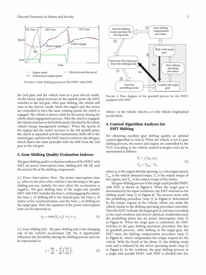
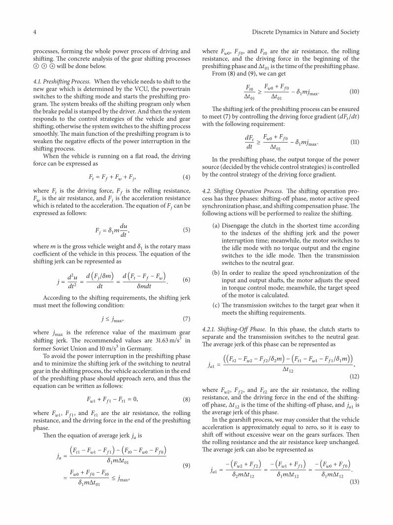
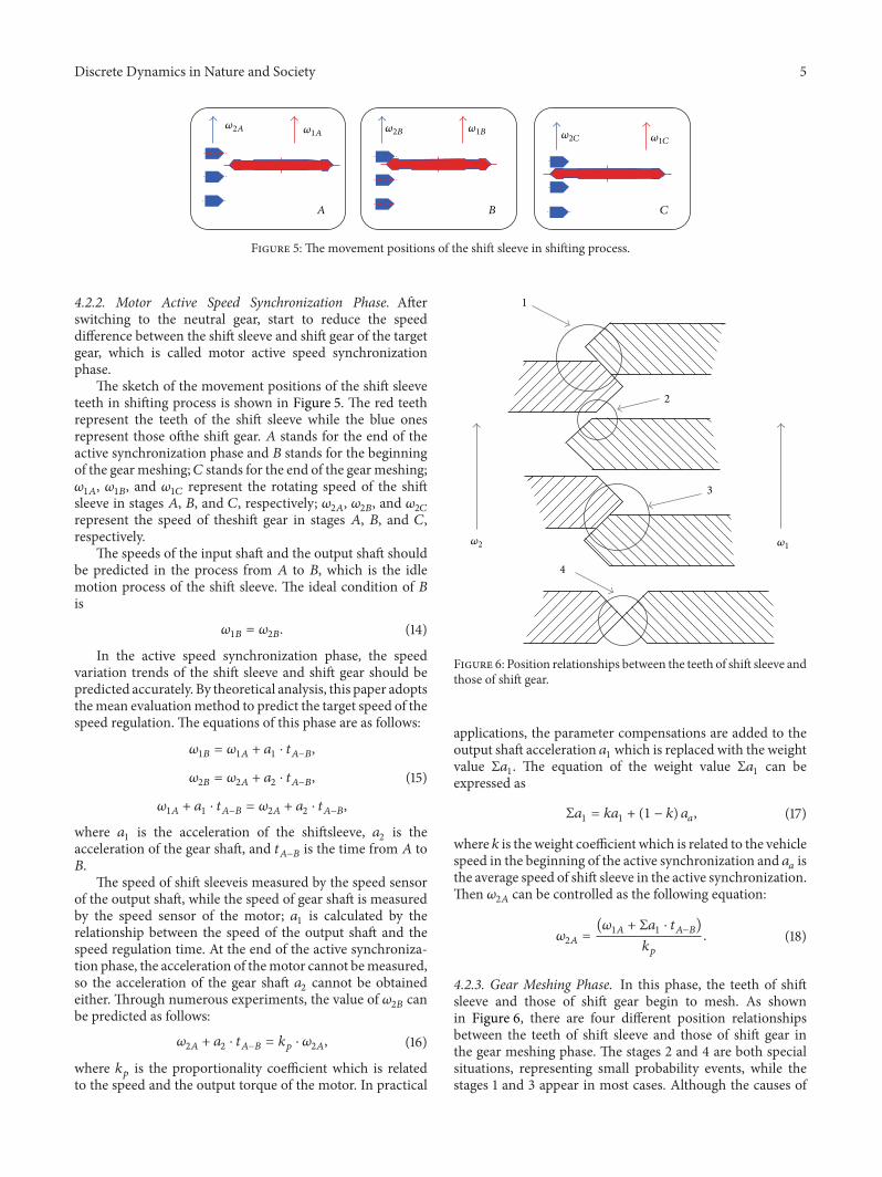
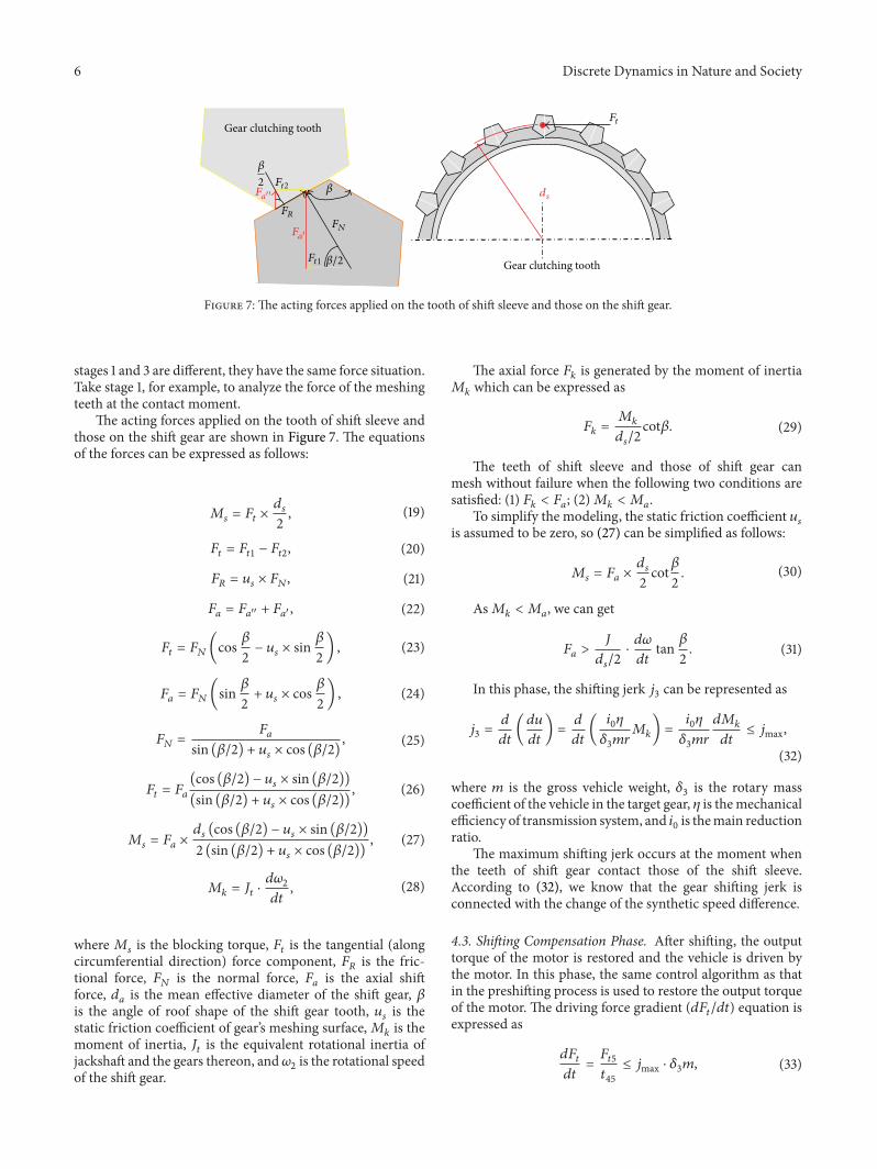
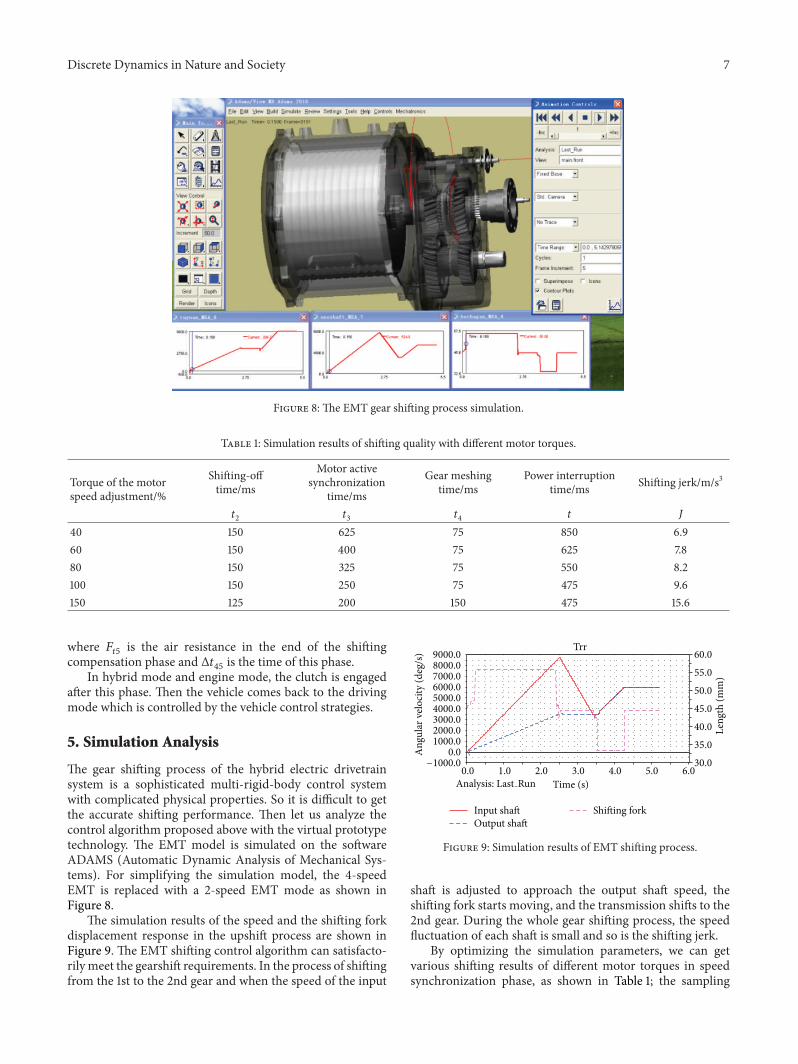
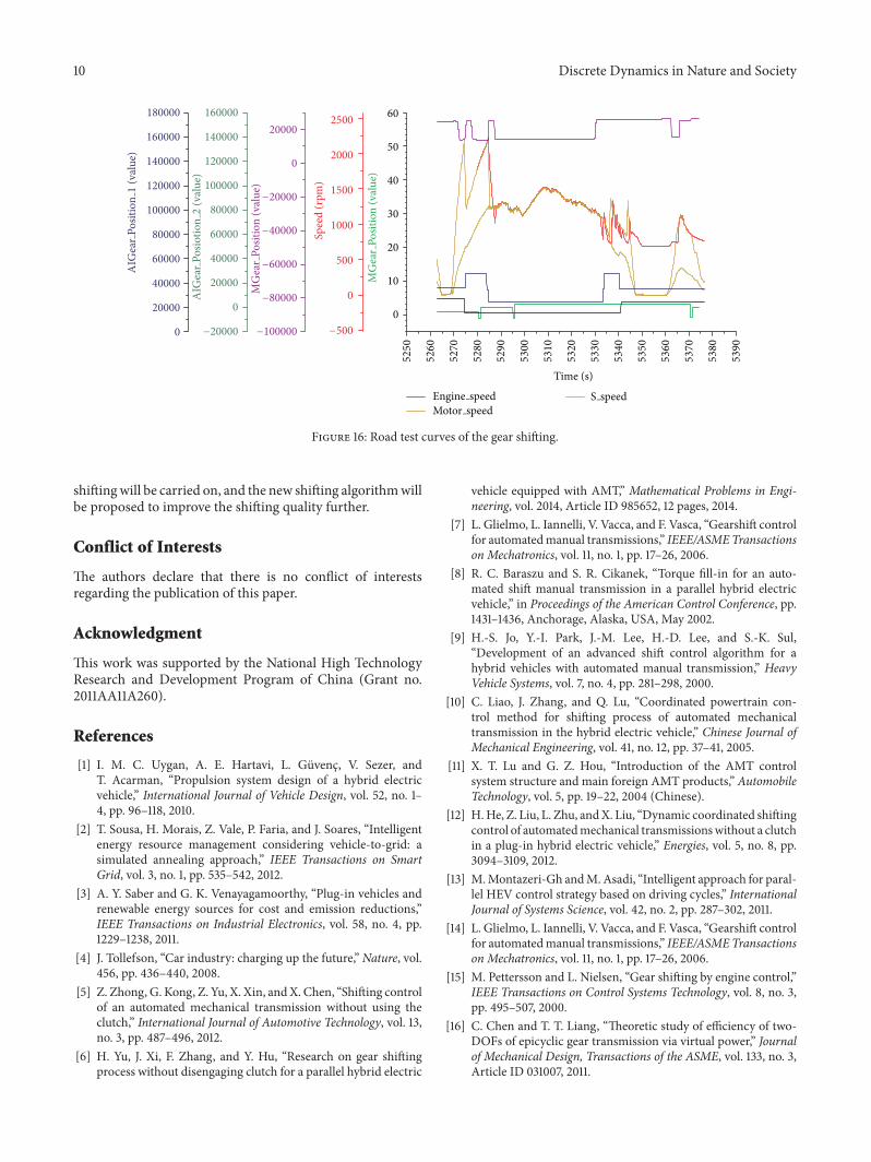