BAMOCAR Motor Controller
46
MANUAL Digital Battery-Motor-Controller BAMOCAR-D3 for EC Servo Motors AC Induction Motors DC-Servo Motors
description
Demo
Transcript of BAMOCAR Motor Controller

Issue 0212 V7
MANUAL
Digital Battery-Motor-ControllerBAMOCAR-D3
forEC Servo Motors
AC Induction MotorsDC-Servo Motors
2
BAMOCAR D3
ContentsPart 1 Hardware
page1 Basis-information
Safety instruction 4,5General 6Application 7Construction 8Technical data 9,10
2 Mmechanical installationImportant instructions 11Dimension BAMOCAR-D3 12,13Assembly 14
3 Electrical installationImportant instructions 15Block diagram 16,17Connection diagram 18EMC 19Connectors 20-22Battery connection 23Power supply, brake 24Motor connection 25Control signals 27-30Schnittstellen 31,32Resolver 33Encoder TTL 34Encoder SINCOS 35Rotorlage bl 36Encoder out-in 37,38LED-monitor 39-41Options 42Guarantee 43
part2 Software -manualpart3 Commissioning- manualpart4 Software-referencepart5 CAN-BUS reference
Conte
ns
Document created with COREL VENTURA 8 TM
and Adobe Acrobat 5.0 TM

3
Basic Information
free

4
BAMOCAR D3
Electronic devices are never fail-safe.
This manual must be carefully read and understood by the professional prior to installationor start-up.Consult the manufacturer or the dealer if anything is unclear.Faulty installation can lead to destruction of the devices.
The BAMOCAR-D series devices are electrical resources (eb) for power electronicsregulating electric currents.They are designed to control ec synchronous motors (blushless dc motors, bldc) inindustrial applications.IP65 protection standardOnly connect to battery.
Regulations and guidelines:Mount and connect the devices and their appropriate components in compliance withtechnical regulations locally applicable and required by law:EG guidelines 2004/108/EG, 2006/95/EG, 2006/42/EG- EN60204-1, EN292, EN50178, EN60439-1, EN61800-3, ECE-R100
ISO 6469, ISO 26262, ISO 16750, ISO 20653, ISO 12100IEC/UL IEC 61508, IEC 364, ICE 664, UL508c, UL840Deregulations VDE 100, VDE 110, VDE 160 andTÜV regulationsTrade association regulations,.VGB4Stvzo §§20/21
Control and power connections can be live eventhough the drive is inoperative.
The dc-bus discharge time is more than 4 minutes.Measure the voltage prior to dismounting
Safe
tyin
stractio
ns
Caution: high voltage DC 900V=.
Electric shock hazard!Danger to personnel!DC-bus discharge - time >4min

Technical Data
5
The user has to ensure :That the drive will be led to a safe operating condition,after an equipment failure-due to malfunction of controlling or regulating unit
Machines, equipments and vehicles are to be further provided
with equipment independent monitoring and safety devices.Un-earthed systems ( for ex. vehicles) must be protectedwith an insulation monitor.No danger shall arise for humans and property .
Assembly-only in non-energized condition-by trained personnel.
Installation work- non-energized condition-only by trained electrical personnel.
Safety regulationsObserve safety-regulations
Setting upSetting up and programming- to be done by trained personnel with knowledge and in electronic drives and software.-observe programming instructions.
Safety regulationsObserve safety regulations.Installation :In case of nstallation in machines, equipments and vehicles, commissioning the equipmentfor the intended purpose is prohibited , until it has been ascertained , that the machines,equipments or vehicles comply with the EC guidelines for machines 2006/ 42/ EG, the EMCguidelines 2004/ 108/ EG and ECE-R100.
The EG- guideline 2004/ 108/ EG with emc regulations EN61000-2 and EN61000-4pertaining to installation and test conditions mentioned in chapter emc instructions arecomplied with.A manufacturer’s clarification can be requested for.Compliance of limiting values , laid down by the emc legislations , is the sole responsibilityof vehicle manufacturers, equipments or machines.
Quality assurance equipment serial numbers , along with date of testing are archived bythe manufacturer for 10 years. Test protocols can be requested for.
Safety symbolsttention :Danger to life
Warning :high voltage important
Safe
tyin
stra
ctio
ns

6
BAMOCAR D3
The digital ac-dc servo drive BOMOCAR D3, together with a motor forms a 4 quadrant drive unit. Driving andbraking with energy recuperation in both directions.based on the installed parameter set , the drive is suitablefor ec synchronous motors, ac asynchronous motors or dc motors. Drive concepts are characterized byvarious advantages and disadvantages.The ec drive ( synchronous motor ) has the highest efficiency and maximum performance per weight andvolume ratio . It is maintenance free and has high control dynamics. The disadvantage is the complicatedregulation in weak field region and the brake torque in case of motor short circuit.The ec synchronous motor ( brushless dc motor ) is , in its electrical construction, a synchronous motor withpermanent magnet rotor and rotary current stator. Physical features resemble to that of dc motors , i.e.,current is proportional to torque and voltage is proportional to rpm.Rpm will be stably controlled till current limit ( max. torque). On overload the rpm sinks with constant current.rectangular rpm � torque � characteristics.Current, rpm and position are measured exactly. the rotary field frequency is non variable, but sets itselfautomatically.motor voltages and motor currents are sinusoidal.The ac drive ( asynchronous motor) has the highest rpm, through its simpler field weakening and does notgenerate braking torque on short circuit. Disadvantage is its size and low efficiency. Rotary field frequency isvariable on consideration of motor specific parameters. ( field oriented regulation ). Motor currents and motorvoltages are sinusoidal. In case of 3 phase alternating current , motor rotation does not take place, when therotary field is shut down or a fault in the output stage exists . Heat loss arises predominantly in the motorstator.DC- drive ( dc motor) has the best synchronization and a high regulation region. Emergency stop can beachieved by directly switching off the battery supply. Disadvantages are the carbon brushes and heatdevelopment in the armature. The drive can rotate at high speeds in case of a fault in the output stage.Current is proportional to the torque and voltage is proportional to rpm. current , rpm and position are exactlymeasured . Rpm is stably regulated till the current limit ( max. torque )On overload, the rpm sinks with constant current. rectangular rpm-torque characteristics. Field weakening ispossible in case of separately excited motors.BOMOCAR D3 can be used as a position controller, torque- or rpm drive . The actual value of speed isgenerated from the sensor unit ( resolver or other) or generated internally ( sensor less). Higher regulationrequirement and control dynamics require a sensor system.
Attention
In case of dc fed dc-, ac- or bl servo drives , energy feedback in the DC- link during braking operation has tobe monitored.External ballast circuitry
InformationBattery � motor regulator ( analog and digital )Battery .:Compact equipmentsFor smaller requirement >>>UNITEK series BAMO -A2/ - A3 10 to 40A
>> UNITEK series BAMOBIL A2/ D2/D3 50 to 450AThyristor regulator and servo drive ( analog and digital)Thyristor regulator >>> UNITEK series CLASSIC 15 to 2000AServo drives DC >>> UNITEK series SERVO DC 5 to 75AServo drives AC/DC >>>UNITEK series SEVO AC 3 to 75A
>> UNITEK series DS 3 to 50A
Genera
l

Technical Data
7
Application in
Machines, equipments, vehicles of all types up to drive capacity of 140 kw especially as4q-servo drives
-in case of highly dynamic acceleration and braking processes.-in case of large control areas-in case of high efficiency-in case of small motor dimensions-in case of constant , silent operation forrpm control, torque control or combined torque- rpm control with or without superimposedposition control.Constant speed drives for conveyor operation, spindle drives, pumps , longitudinal andtransverse drives.Drives for synchronized operation of multiple motors.
Used in:Battery operated vehicles like electric vehicles, electric boats, lift – trucks, transportsystems as well as battery operated machines and equipments like automatic mountingmetal processing machines, x- y tables, grocery machines, robots and handling systems,stacker cranes and stone processing machines and in many battery operated applications.
The motors and controllers are constructed with IP 65 protection ,-compact ,-for harsh conditions,-for high dynamic overload,- maintenance free.
Observe :Braking energy would be fed back in to the battery.The battery must be able to absorb the braking energy.
In case of unearthed systems ( vehicles, it – networks) , theinsulation between the parts which come in contact and HV-voltages should be monitored by an independent insulationmonitoring watch dog.
Applic
atio
n

8
BAMOCAR D3
Construction :
Compact equipmentAcc. to VDE-DIN-EG- standards.IP 65 protection against accidental contact with power connections.
Power electronics for ( S1 operation ) 125 A, 200 A,(peak 250A, 400A)Input power range nom. 12 to 700 V =Liquid cooling ( special construction air cooling)Unified digital controller electronics)Independent 12/ 24V DC chopper power unit for auxiliary power.
Galvanic isolation-Galvanic isolation between power connector, motor connector and all other
control connectors-Galvanic isolation between auxiliary voltage and all other voltages.-Housing and radiator assembly are galvanically isolated from all electric parts.-The air and creepage distances comply with VDE.- No internal insulation monitor. Y2 capacitors to housing.
The following are used:IGBT – power semi conductor
- Generously dimensioned.- Only commercially available parts in industry standard.- SMD –mounting- 7 segment led indicators ( option)
Features
* Battery connection 12 v = to 700 volts = ( dc supply, observe limitations)* Independent auxiliary supply 24 v = or 12 v =* Digital interfaces RS 232, can- bus ( additional option)* 2 analog inputs, programmable differential inputs* 4 digital in- out puts, programmable, optically isolated* Reference value ramps linear, non linear ( s – function)* Release and limit -switch logic.* BTB – operation ready, solid state relay contact.* Position , rpm and torque control* Resolver or encoder – incremental encoder TTL , SINCOS 1Vss,* Rotor positon + bl tacho.* Encoder output or 2. encoder input.* Static and dynamic current limit* Unified full digital regulator unit* Safety shutdown in case of over voltage, under voltage and over temperature from
motor.* Self protected short circuit proof power part. processor independent hardware -shut
down in case of short circuit, earth fault , over voltage and over temperature ofamplifier.
Featu
re
Technical Data
9
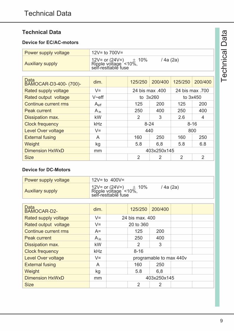
Technical Data
Device for EC/AC-motors
Power supply voltage 12V= to 700V=
Auxiliary supply12V= or (24V=) ± 10% / 4a (2a)Ripple voltage <10%,self-resttable fuse
DataBAMOCAR-D3-400- (700)- dim. 125/250 200/400 125/250 200/400
Rated supply voltage V= 24 bis max .400 24 bis max .700
Rated output voltage V~eff to 3x260 to 3x450
Continue current rms Aeff 125 200 125 200
Peak current A io 250 400 250 400
Dissipation max. kW 2 3 2.6 4
Clock frequency kHz 8-24 8-16
Level Over voltage V= 440 800
External fusing A 160 250 160 250
Weight kg 5.8 6,8 5.8 6.8
Dimension HxWxD mm 403x250x145
Size 2 2 2 2
Device for DC-Motors
Power supply voltage 12V= to 400V=
Auxiliary supply12V= or (24V=) ± 10% / 4a (2a)Ripple voltage <10%,self-resttable fuse
DataBAMOCAR-D2- dim. 125/250 200/400
Rated supply voltage V= 24 bis max. 400
Rated output voltage V= 20 to 360
Continue current rms A= 125 200
Peak current A io 250 400
Dissipation max. kW 2 3
Clock frequency kHz 8-16
Level Over voltage V= programable to max 440v
External fusing A 160 250
Weight kg 5.8 6,8
Dimension HxWxD mm 403x250x145
Size 2 2
Tech
nic
alD
ata
10
BAMOCAR D3
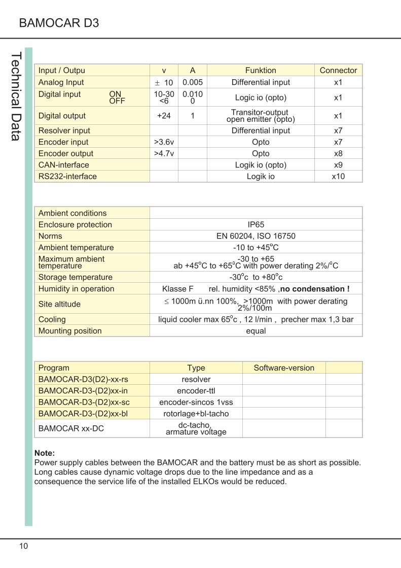
Input / Outpu v A Funktion Connector
Analog Input ± 10 0.005 Differential input x1
Digital input ONOFF
10-30<6
0.0100 Logic io (opto) x1
Digital output +24 1 Transitor-outputopen emitter (opto) x1
Resolver input Differential input x7
Encoder input >3.6v Opto x7
Encoder output >4.7v Opto x8
CAN-interface Logik io (opto) x9
RS232-interface Logik io x10
Ambient conditions
Enclosure protection IP65
Norms EN 60204, ISO 16750
Ambient temperature -10 to +45oCMaximum ambienttemperature
-30 to +65ab +45oC to +65oC with power derating 2%/oC
Storage temperature -30oc to +80ocHumidity in operation Klasse F rel. humidity <85% ,no condensation !
Site altitude £ 1000m ü.nn 100%, >1000m with power derating2%/100m
Cooling liquid cooler max 65oc , 12 l/min , precher max 1,3 bar
Mounting position equal
Program Type Software-version
BAMOCAR-D3(D2)-xx-rs resolver
BAMOCAR-D3-(D2)xx-in encoder-ttl
BAMOCAR-D3-(D2)xx-sc encoder-sincos 1vss
BAMOCAR-D3-(D2)xx-bl rotorlage+bl-tacho
BAMOCAR xx-DC dc-tacho,armature voltage
Note:Power supply cables between the BAMOCAR and the battery must be as short as possible.Long cables cause dynamic voltage drops due to the line impedance and as aconsequence the service life of the installed ELKOs would be reduced.
Tech
nica
lData

11
Mechanical Installation
Important instruction
Check the equipment for mechanical damageInstall only defect-free equipmentsAssembly only in non-energized condition
Disconnect the positive and negative terminals of the battery,
disconnect DC supply.
Assembly only by trained personnel
The installation position is discretionary in case of equipments withliquid cooling.In case of very low heat dissipation, the equipment is shut down byits thermal monitoring system.Equipment fitment holes to be obtained from dimension drawing or drill plannot to be traced out from the equipment itself.
Filter and choke to be mounted close to the equipment.Connect cable screens with mounting area so as to have surface contact.
Lay power cables ( battery and motor cables ) well separated from signal cablesobserve minimum cable cross –section.
Unscreened cable ends to be as short as possible.
Secure earth connection from housing to ground plane( vehicle ground, control panel –earth)Use vibration resistant screw joints.
Mech
anic
alI
nst
alla
tion

12
BAMOCAR D3
Dim
ensio
ns
Screw for hex key BAMOCAR

13
Mechanical Installation
Ass
em
bly
Liquid cooler
Connection
hose connection metall 13mm
inlet temperature 50o grad c
flow max 12l/minpressure max 1,3 bar

14
BAMOCAR D3
frei
Asse
mbly

15
Electrical Installation
Important instructionsThe connection instructions are classified according to the connector numbers respectivelyand are mandatory.
All further instructions hereto are non-binding.The input and output lines can be modified and supplemented, under consideration ofelectrical regulations and guidelines
Regulations to be observed areConnection and operational instructionLocal regulationsEC-regulations like ec machinery directive 2006/ 42/ EG-EC-regulations for vehicles EC-R 100, ISO 6469, ISO 26262VDE , TÜV and provisions of professional association.
Electrical installation only in non-energized condition.
Observe safe activation.
Insert shorting bar
Put up warning boards
Installation only by trained personnel in electronics
Compared connected load with type – identification plate details.Observe correct input of power and auxiliary voltage.Lay power cable and control cable spatially separated.Follow emc-guidelines for screen connection and earthing procedures.Use correct cable cross- section.
Use external insulation watch dog
AttentionPoor or under dimensioned cable connection between the battery andthe equipment can lead to equipment damage.( braking energy)
Attention : Power cables from fmc iii to batteries to be as short aspossible. Long cables lead to dynamic voltage-drops due to theirimpedance.These burden the installed capacitors and shorten the life span.
Ele
ctrica
lInst
alla
tion

16
BAMOCAR D3
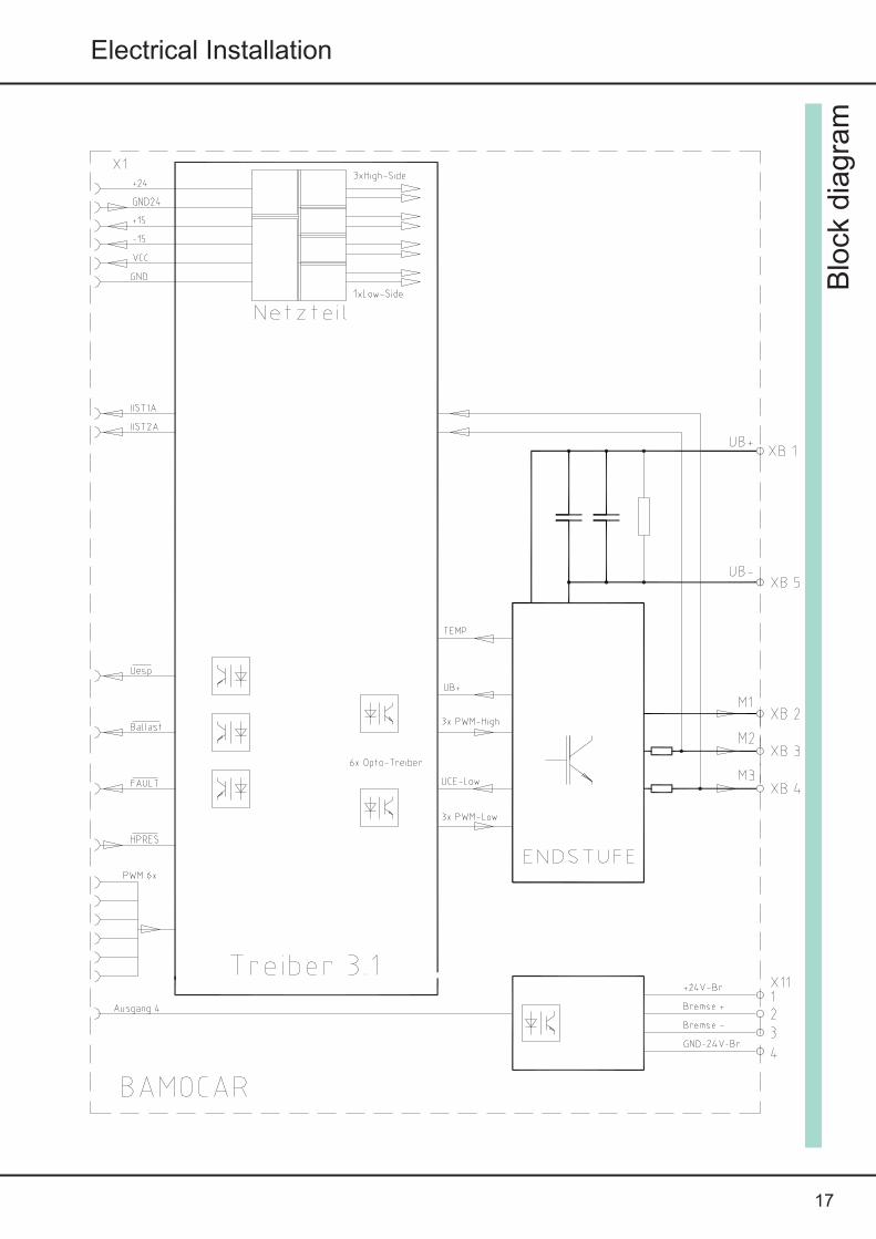
Blo
ckdia
gra
m
17
Electrical Installation
Blo
ckdia
gra
m
18
BAMOCAR D3
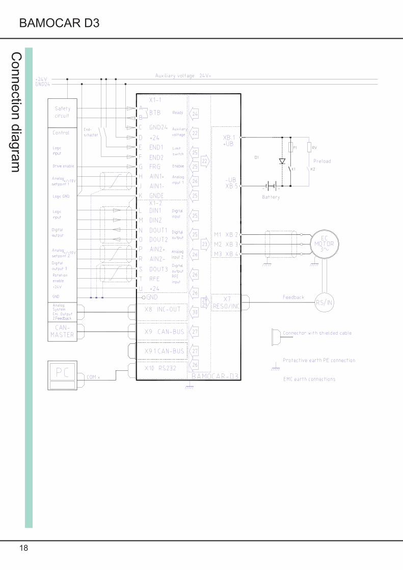
Connectio
ndia
gra
m

19
Electrical Installation
Equipments comply with the EC- regulations 2004/ 108/ EG and standards EN 61800-3 according to thefollowing installation and test conditions.Mounting :The equipment is conductingly mounted on a bare , aluminum plate with dimensions 500 x 500 x 5mm.mounting plate corresponds to ground plane( vehicle ground , control panel ground )Motor casing above 10 mm2 connected to ground .Equipment ground x- agnd above 1.5 mm 2 connected to the mounting plate( ground) .Housing connected with mounting plate ( ground)Control connections:Signal wires are screened, analog signal wires are twisted and screened .Screen: surface contact with the mounting plate ( ground)Battery connection:360 V DCMotor connection :Motor cables are screened, and have surface contact with the mounting plate ( ground)In case of installation in machines and equipments , the commencement ofoperation of the equipment in accordance with the provisions is prohibited, till it isconfirmed, that the machine or equipment complies with the ec � regulations 2006/42/ EG and the emc � regulations 2004/ 108/ eg,in case of vehicles ECE-Rr83, ECE-R100.A manufacturer�s declaration can be requested for.
EM
C

Connectors
20
BAMOCAR D3
Connecto
rs
Connector X1 IN / Output
a brown BTB BTB-Readyb red BTBc pink GND Auxiliary voltage 0d yellow +24 Auxiliary voltage+e gree END1/LMT1 Limit switch1f blue END2/LMT2 Limit switch2g violett FRG/RUN Enableh gray AIN1+ Analog-Input1j white AIN1-k black GNDE Logik-GNDl br-green DIN1 Digital-Input1m br-yellow DIN2 Digital-Input2n ws-green DOUT1 Digital-Output1o red-blue DOUT2 Digital-Output2p wh-yellow AIN2+ Analog-Input2r wh-red AIN2-s wh-gray DOUT3 Digital-Output3t wh-black RFE Rotation Enableu ws-blue +24v Auxiliary voltage +Connector Binder 99-5662-15-19
Connector Binder 99-0429-15-04
Connector X11 Brake
1 +24 v-br2 Brake +3 Brake -4 GND-24V-Br
Connector Binder 79-3464-52-06
Connector X 10 RS232
1 brown r2in2 white txd3 blue t2ou4 black t2ou5 gray rxd6 pink gnd
Connector X9Binder 99-0436-14-05Connector X9.1Binder 99-0437-14-05
Connector X9, X9.1CAN-BUS
1 PE2 (Voltage in)3 CAN GND4 CAN Hh5 CAN Ll

21
Electrical Installation
Connect
ors
Connector X7Resolverabc sin1de cos2fg ref2h temp signaljk ref1l temp gndm cos1no sin2p
Connector X7ENC-TTLa canal ab canal /nc canal bd voltage +5ve canal nf canal /bg canal /ah temp signalj temp gndk rotor 3l gndm rotor2no rotor1p
Connector X7SIN/COSa canal ka+b canal kr+c canal kb+d voltage +5ve canal kr+f canal kb-g canal ka-h temp signalj temp gndk canal kd-l voltage gndm canal kc+n canal kd+o canal kc-
Connector X8Output / 2 Input ENC-TTLa voltage +5vc selekt ine canal ag canal nj canal bl canal /bm canal /nn canal /ao voltage GNDt output dac1u GND dac1Connector Binder 99-5651-15-14
Feedback- connector X7
Connector Binder 99-5661-15-19
At all connectors: View the plug on solder-crimp side.
Connector X7bla mp-tachobc tacho 1d voltage +15ve tacho 2fg tacho 3h temp signalj temp gndk rotor 3l versorgung gndm rotor2no rotor 1p

Power connectors 1000V / 400A
Connector socket plus Pfisterer p1 (350 205-301 (-302))
Connector socket minus Pfisterer p1 (350 205-301)
Motor connector socket Pfisterer p1 (350 205-301)
Connector plug plus Pfisterer connector straight p1 (350205-002..)or connector angle p1 (350205-102)
Connector plug minus Pfisterer connector straight p1 (350205-001..)or connector angle p1 (350205-101)
Connector plugr motor Pfisterer connector straight p1 (350205-001)or connector angle p1 (350205-101)
22
BAMOCAR D3
Pow
er
connecto
rs

23
Electrical Installation
Batt
ery
connect
ionsConnection to the battery
WarningThe max. supply voltage UB + 400 (700) must not be exceeded at any time(not even for short intervals)!Danger of damage!F1 = safety fuses
Connection has no protection against reverse polarity.
If the polarity of the connection is wrong, the device will be destroyed
TypeConnectioncross-sectionmm2 AWG
Fuse A
-125/250 25 2 160
-200/400 35 1 250
Battery connecting line <2m. For conductor lengths from 2 to 10m more powerful. Use an additionalcapacity for conductor lengths superior to 10m!!
Attention:
DC-Linkat 400V 800mFat 700V 320mFResistorRv ca. 40 ohm 10wInrush-current over k2ca.10AEnable (RUN) only atswitched main contactor K1
Programming exampleOutput dout1 switches the relay k3 when the dclink voltage ( l_o/u voltage) is higher than thevariable 1.
Prinzip preload

24
BAMOCAR D3
Auxilia
ryvo
ltage
Bra
ke
Auxiliary power connectionMains independent Auxiliary dc voltage 12 V = up to 24 V = +/- 10 % / 4 up to 2 A
The Auxiliary voltage has- galvanic connection to logic voltage
- internal self healing fuse- emc filter- external fuse only for line protection
Input voltage 12...24 V DC X 1: 4GND 24 X 1 :3Ripple 10 %Inrush current 4ARated current in case of 12 v 1.4 A
in case of 24 v 0.9 A
Attention : For internal power supply ( 1,4 A) , also the sum total currents of output( dout) has to be fed from the 12/24 V system.
Attention : In case of Auxiliary voltage less than 10 V, including during short time dropouts, the internal power supply system shuts down. Temporary data in ram memory areerased. Digital rpm and torque reference are reset to 0, fault indication 1 ( hardware fault ) .
Indication ok in status is off.

25
Elektrical Installation
Motor – power connectionUse only UNITEK approved, electronically commutated synchronous motors( brushless dc motors, ec motors) with resolver or incremental encoder .Refer Appendix A ( motor specific connection and parameter guidelines)
Connection sequence
Cable cross –section minimum.
Moto
rco
nnect
ion
Cable indication M1 M2 M3
Motor phase U V W
Connector xb:2 xb:3 xb:4
Correct wiring is essential !
Type BAMOCAR -Dx -125 -200
Cable dim. mm2 25 35
Cable dim. AWG 2 1
Motor cables,3 wires + simply shieldedprotective earth conductor for600V~, 1000V=, shield capacity150pF/m.
Motor choke.Only required upwards of a shield capacity of >5nF. approx. 25m motor cable.
Magnetic rings
Against HF failures of the sensor systems. Slide the rings onto the motor lines.
Shielded connection:Surface connection at entry to control cabinet. Surface or as short as possible connectionat the motor end.

26
BAMOCAR D3
27
Electrical Installation
Contr
olC
onnect
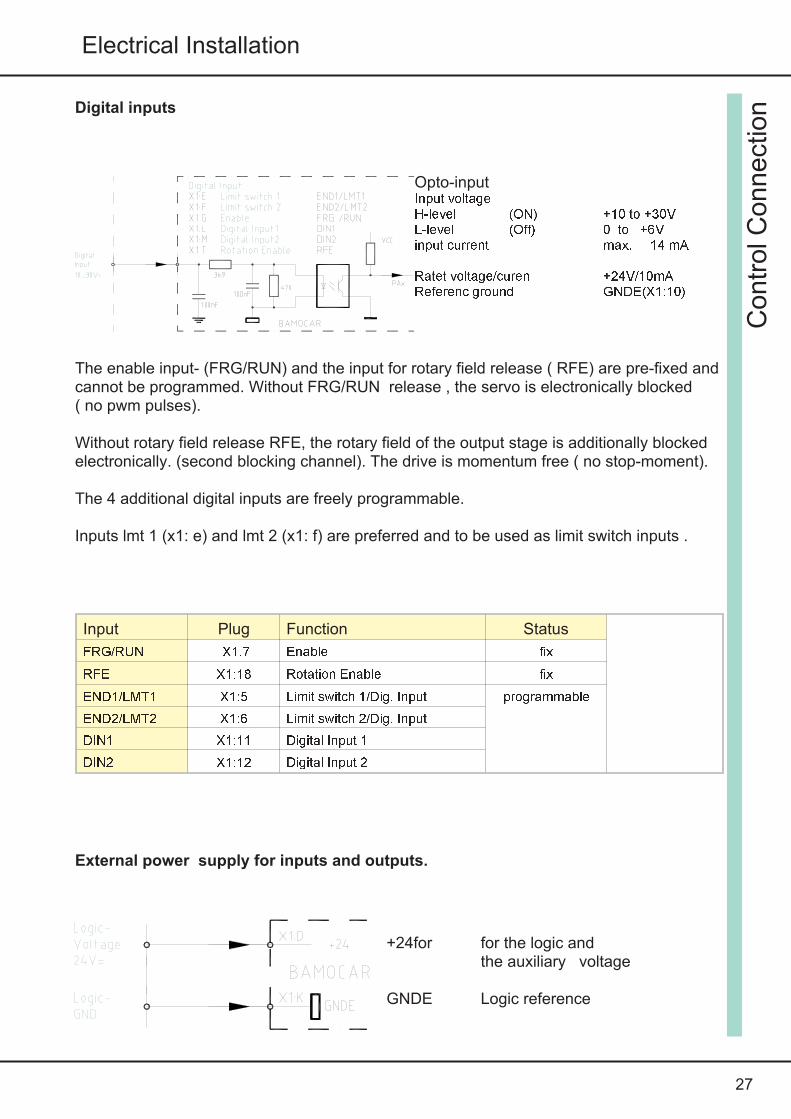
ionDigital inputs
The enable input- (FRG/RUN) and the input for rotary field release ( RFE) are pre-fixed andcannot be programmed. Without FRG/RUN release , the servo is electronically blocked( no pwm pulses).
Without rotary field release RFE, the rotary field of the output stage is additionally blockedelectronically. (second blocking channel). The drive is momentum free ( no stop-moment).
The 4 additional digital inputs are freely programmable.
Inputs lmt 1 (x1: e) and lmt 2 (x1: f) are preferred and to be used as limit switch inputs .
Input Plug Function Status
FRG/RUN X1.7 Enable fixRFE X1:18 Rotation Enable fixEND1/LMT1 X1:5 Limit switch 1/Dig. Input programmableEND2/LMT2 X1:6 Limit switch 2/Dig. InputDIN1 X1:11 Digital Input 1DIN2 X1:12 Digital Input 2
External power supply for inputs and outputs.
Opto-inputInput voltageH-level (ON) +10 to +30VL-level (Off) 0 to +6Vinput current max. 14 mARatet voltage/curen +24V/10mAReferenc ground GNDE(X1:10)
+24for for the logic andthe auxiliary voltage
GNDE Logic reference
28
BAMOCAR D3
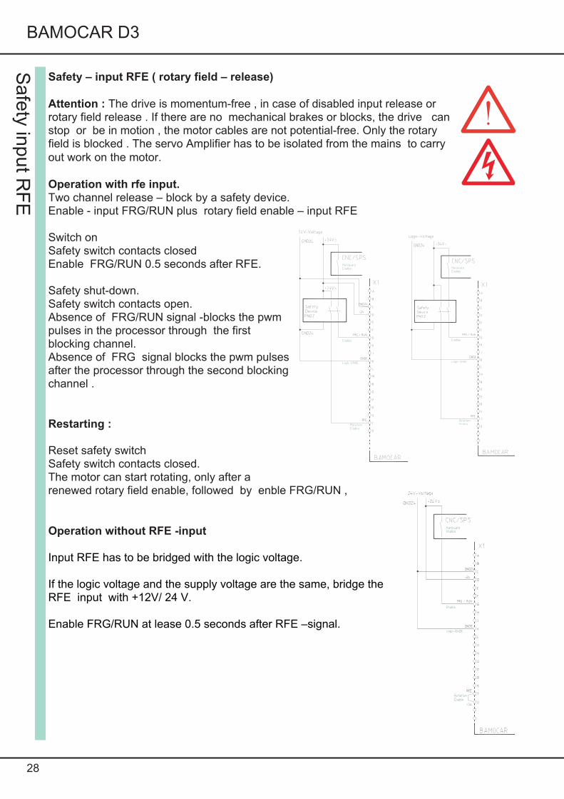
Safety – input RFE ( rotary field – release)
Attention : The drive is momentum-free , in case of disabled input release orrotary field release . If there are no mechanical brakes or blocks, the drive canstop or be in motion , the motor cables are not potential-free. Only the rotaryfield is blocked . The servo Amplifier has to be isolated from the mains to carryout work on the motor.
Operation with rfe input.Two channel release – block by a safety device.Enable - input FRG/RUN plus rotary field enable – input RFE
Switch onSafety switch contacts closedEnable FRG/RUN 0.5 seconds after RFE.
Safety shut-down.Safety switch contacts open.Absence of FRG/RUN signal -blocks the pwmpulses in the processor through the firstblocking channel.Absence of FRG signal blocks the pwm pulsesafter the processor through the second blockingchannel .
Restarting :
Reset safety switchSafety switch contacts closed.The motor can start rotating, only after arenewed rotary field enable, followed by enble FRG/RUN ,
Operation without RFE -input
Input RFE has to be bridged with the logic voltage.
If the logic voltage and the supply voltage are the same, bridge theRFE input with +12V/ 24 V.
Enable FRG/RUN at lease 0.5 seconds after RFE –signal.
Safe
tyin
put
RF
E
29
Electrical Installation
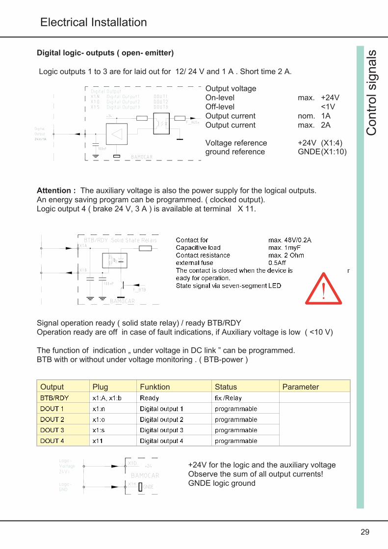
Digital logic- outputs ( open- emitter)
Logic outputs 1 to 3 are for laid out for 12/ 24 V and 1 A . Short time 2 A.
Attention : The auxiliary voltage is also the power supply for the logical outputs.An energy saving program can be programmed. ( clocked output).Logic output 4 ( brake 24 V, 3 A ) is available at terminal X 11.
Signal operation ready ( solid state relay) / ready BTB/RDYOperation ready are off in case of fault indications, if Auxiliary voltage is low ( <10 V)
The function of indication „ under voltage in DC link ” can be programmed.BTB with or without under voltage monitoring . ( BTB-power )
Contr
ols
ignals
Output voltageOn-level max. +24VOff-level <1VOutput current nom. 1AOutput current max. 2A
Voltage reference +24V (X1:4)ground reference GNDE(X1:10)
Contact for max. 48V/0.2ACapacitive load max. 1myFContact resistance max. 2 Ohmexternal fuse 0.5AffThe contact is closed when the device is ready for operation.State signal via seven-segment LED
Output Plug Funktion Status Parameter
BTB/RDY x1:A, x1:b Ready fix /RelayDOUT 1 x1:n Digital output 1 programmableDOUT 2 x1:o Digital output 2 programmableDOUT 3 x1:s Digital output 3 programmableDOUT 4 x11 Digital output 4 programmable
+24V for the logic and the auxiliary voltageObserve the sum of all output currents!GNDE logic ground

30
BAMOCAR D3
Analog inputs +/- 10V
Inputs Terminal Basic function Voltage Status Parameter
Ain1+,Ain1- X1:h, X1:j rpm � reference value +/-10V prog.Ain2+,Ain2- X1:p, X1:r current limit +/-10V prog.
Characteristics
Differential input Ain1+/Ain1- Ain2+/Ain2-
input impedance 70kOhmlimit voltage +/-12Vresolution 11bit + sign
The direction of rotation of the motor can be changed by reversing the +/- polarity at thedifferential input, by a logic- input or by programming .
In case of digital reference value ( RS 232, x bus), analog input Ain 1 can be programmedas external rpm limit and the Analog input Ain 2 can be programmed as external analogcurrent limit.
Analog output +/- 10 V
Output Terminal Basic function Voltage Status Parameter
Aout1 x8:t rpm- Actual value +/-10v prog.gnd x8:u signal-gnd 0v fixed
Contro
lsignals

31
Electrical Installation
Serial interface RS232
The Amplifier BMOCAR-D3 is programmed and commissioned through the PC interfaceRS232 .
The software is described in the software-manual DS NDrive.Connection between the BAMOCAR-D3 ( d-connector X10 ) and the serial interface onlythrough a null modem-cable.Do not use null modem-link cable!Cable to be plugged in only in de-energized condition.Select the interface baud rate in NDrive as 115200.
The serial interface is galvanicallycoupled with the device - zero (GND) .
Null modem cablePin assignment. Solder side.Contact shield with the plug housing.Cable length max. 10m
Inte
rface
BAMOCARConnector X 10 RS2321 R2in2 Txd3 T2ou4 Dtr5 Rxd
32
BAMOCAR D3
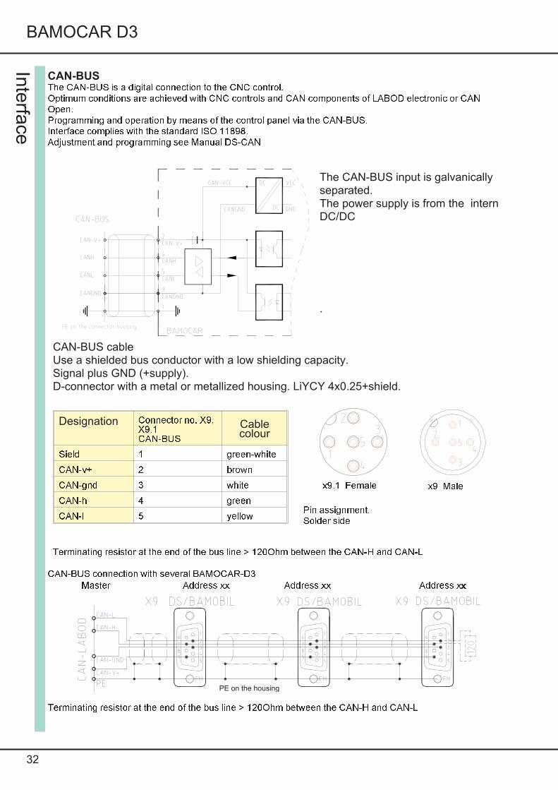
CAN-BUSThe CAN-BUS is a digital connection to the CNC control.Optimum conditions are achieved with CNC controls and CAN components of LABOD electronic or CANOpen.Programming and operation by means of the control panel via the CAN-BUS.Interface complies with the standard ISO 11898.Adjustment and programming see Manual DS-CAN
CAN-BUS connection with several BAMOCAR-D3Master Address xx Address xx Address xx
Terminating resistor at the end of the bus line > 120Ohm between the CAN-H and CAN-L
Inte
rface
The CAN-BUS input is galvanicallyseparated.The power supply is from the internDC/DC
.
Terminating resistor at the end of the bus line > 120Ohm between the CAN-H and CAN-L
Designation Connector no. X9,X9.1CAN-BUSCablecolour
Sield 1 green-whiteCAN-v+ 2 brownCAN-gnd 3 whiteCAN-h 4 greenCAN-l 5 yellow
CAN-BUS cableUse a shielded bus conductor with a low shielding capacity.Signal plus GND (+supply).D-connector with a metal or metallized housing. LiYCY 4x0.25+shield.
Pin assignment.Solder side
x9.1 Female x9 Male
PE on the housing

33
Elektrical Installation
Resolver - connection.Applicable only for BAMOCAR D3 xx-RS
The resolver is an absolute measuringsystem for motor rotation. It is robustand insensitive against high motortemperatures.The construction is similar to a rotatingtransformer.The rotor is fed from the reference( 10 kHz)The stator delivers the sine and cosine -signals , that are modulated from therotational frequency .The Amplitudes of these signals will beevaluated and digitized in the servoAmplifier.The resolution will be optimally set to 10,12 or 14 bits automatically.The maximum possible rpm is 50000( 10 bit)The digitized signals are used for thepolar wheel Angle, position and speedcontrol and for incremental outputs.
Use only UNITEK approved motors (Appendix A)with 2, 4, 6 or 8 pole resolverFollow motor specific connection chart ( RS)Connector x7 : 19 pole round connectorConnecting cable : 4 x 2 core twisted pair and screened, plus total shield.
In case of drag chain use only suitable cable.Cable length: In case of length > 25 m, use only high quality resolver cable with better screen
properties .Screen connection At connector x7, connect all screens together with the casing .
At the motor connector , connect the total shield with the connector housing.Individual parameter refer software manual DS NDrive.
Reso
lver
Connector X7ResolverAbc sin1de cos2fg ref2h temperature signaljk ref1l temperature gndm cos1no sin2p
34
BAMOCAR D3
Enco
der
TT
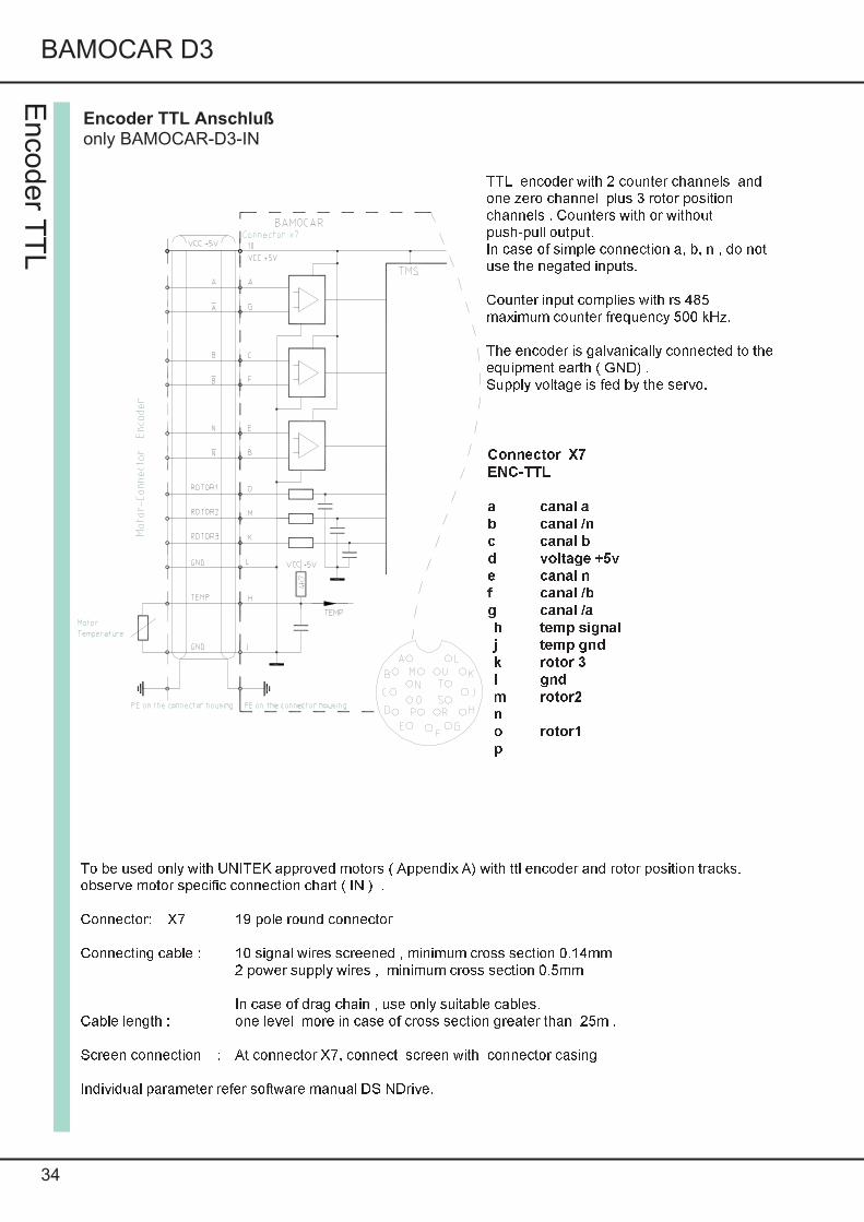
LTo be used only with UNITEK approved motors ( Appendix A) with ttl encoder and rotor position tracks.observe motor specific connection chart ( IN ) .Connector: X7 19 pole round connectorConnecting cable : 10 signal wires screened , minimum cross section 0.14mm
2 power supply wires , minimum cross section 0.5mmIn case of drag chain , use only suitable cables.
Cable length : one level more in case of cross section greater than 25m .Screen connection : At connector X7, connect screen with connector casingIndividual parameter refer software manual DS NDrive.
Encoder TTL Anschlußonly BAMOCAR-D3-IN
TTL encoder with 2 counter channels andone zero channel plus 3 rotor positionchannels . Counters with or withoutpush-pull output.In case of simple connection a, b, n , do notuse the negated inputs.Counter input complies with rs 485maximum counter frequency 500 kHz.The encoder is galvanically connected to theequipment earth ( GND) .Supply voltage is fed by the servo.
Connector X7ENC-TTLa canal ab canal /nc canal bd voltage +5ve canal nf canal /bg canal /ah temp signalj temp gndk rotor 3l gndm rotor2no rotor1p

35
Electrical Installation
SIN / COS 1Vss Anschlussonly BAMOCAR-D3-xx-SC
SIN COS 1Vss connectiononly in case ofBAMOCAR-D3�xx-SCEncoder with 2 analog sinusoidalcounter track and a track zero plustwo commutation tracks.Differential signals 1 Vsssignal differenceMaximum counter frequency500 khz.The encoder is galvanicallyconnected to equipment ground( GND).Servo feeds the supply voltage 5VOptimum resolution will beautomatically selected.
Use only UNITEK approved motors ( Appendix A ) with sin/ cos sensor ( SC).observe motor specific connection chart ( SC)Connection terminal X 7 19 pole round connectorConnecting cable 4 x core signal cable , drill �screened
Minimum cross section 0.14mm2 core signal screened cable minimum cross section 0.14 mm4 core power supply cables, temperature minimum cross section 0.5 mm
Cable type : (4x(2x0.14)+(4x0.14)c+4x0.5)cUse appropriate cable in case of drag chain.
Cable length in case of length > 25m, cross section one step higher.Screen connection At connector X 7 connect screen with the connectorcasing.
At motor connector connect screen with connector casing.Individual parameter refer software manual DS NDrive.
SIN
/CO
S1vs
s
Connector X7SIN/COSa canal ka+b canal kr+c canal kb+d voltage +5ve canal kr+f canal kb-g canal ka-h temp signalj temp gndk canal kd-l voltage gndm canal kc+n canal kd+o canal kc-
36
BAMOCAR D3
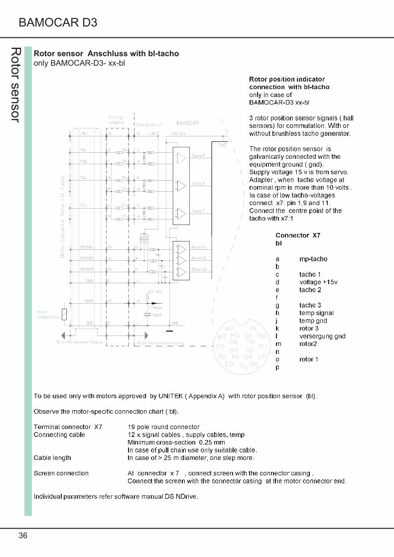
Rotor sensor Anschluss with bl-tacho
only BAMOCAR-D3- xx-bl
Rotor position indicatorconnection with bl-tachoonly in case ofBAMOCAR-D3 xx-bl3 rotor position sensor signals ( hallsensors) for commutation. With orwithout brushless tacho generator.The rotor position sensor isgalvanically connected with theequipment ground ( gnd).Supply voltage 15 v is from servo.Adapter , when tacho voltage atnominal rpm is more than 10 volts .In case of low tacho-voltagesconnect x7: pin 1,9 and 11.Connect the centre point of thetacho with x7:1
To be used only with motors approved by UNITEK ( Appendix A) with rotor position sensor (bl).Observe the motor-specific connection chart ( bl).Terminal connector X7 19 pole round connectorConnecting cable 12 x signal cables , supply cables, temp
Minimum cross-section 0.25 mmIn case of pull chain use only suitable cable.
Cable length In case of > 25 m diameter, one step more.Screen connection At connector x 7 , connect screen with the connector casing .
Connect the screen with the connector casing at the motor connector end.Individual parameters refer software manual DS NDrive.
Roto
rse
nso
r
Connector X7bla mp-tachobc tacho 1d voltage +15ve tacho 2fg tacho 3h temp signalj temp gndk rotor 3l versorgung gndm rotor2no rotor 1p
37
Electrical Installation
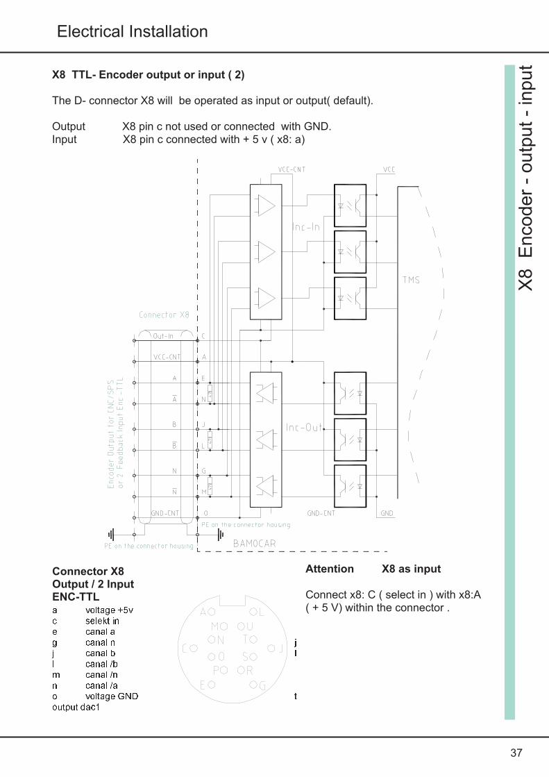
X8 TTL- Encoder output or input ( 2)
The D- connector X8 will be operated as input or output( default).
Output X8 pin c not used or connected with GND.Input X8 pin c connected with + 5 v ( x8: a)
Attention X8 as input
Connect x8: C ( select in ) with x8:A( + 5 V) within the connector .
X8
Enco
der
-outp
ut
-in
put
Connector X8Output / 2 InputENC-TTLa voltage +5vc selekt ine canal ag canal n jj canal b ll canal /bm canal /nn canal /ao voltage GND toutput dac1

X8 as TTL-Encoder outputSensor signals( feedback ) from the motors will be given as ttl – encoder signals for cnccontrol at d connector X8.
Encoder output is potentially isolated .
Power is supplied through the senor cable from the cnc/ sps control.Power supply + 5 V +/ - 0.2 VoltsOutput signal complies with RS 485.
The resolution is programmable in case of rs and sc. ( parameter 0xa4, bit 1), same as incase of in sensor – pulse rate.
X8 as TTL Encoder input
Attention : X8 pin C ( select in) must be connected to X8 pin A ( + 5V)!!
The encoder input is potentially isolatedpower supply is done through the sensor cable.
Option : internal supply from servo input signals comply with RS 485
Maximum input frequency 200 kHz
Encoder input can be programmed for various functions.Refer software description DS-NDrive.
38
BAMOCAR D3
X8
Enco
der
-outp
u-
inpu
Pulse signals(motor revolving clockwise)
Output level low <0.5V, high >4.5VSlope <0.1msZero pulse min. 0.2msOutput frequency max. 200kHz
Pulse/rpm- for RS, SC programmable- for IN encoder no.of pulses

39
Electrical Installation
Light indications on BAMOCAR-D3
In case of „ normal“ condition , the green 7 segment indicator and decimal points glowindicating operational condition ( status- indication)
In case of „ fault“ the red led „ FAULT“ glows and the 7 segment indicator indicates the faultnumber.
In case of „ warning „ the red fault led blinks and the 7 segment display alternativelyindicates the status and the warning number.
Status indication on servo
Display Point/segment State State of NDrive
flashingdark
Processor activeAuxiliary supply failure or internal fault in equipment
flashingbrightdark
Start condition after reset ( auxiliary voltage on/ offThe first release ends the blinking conditionDrive releasedDrive blocked ( not released)
ok = 0ok = 1 , ena = 1ok = 1 , ena = 0
bright rpm = zero ( indication- stand still condition) n0 = 1
bright Drive rotates clock wise , n presently positive n0 = 0
bright Drive rotates anti-clock wise , n presently negative n0 = 0
flashingbrightdark
Motor current reduced to continuous current icnsMotor current at current limit imaxNormal operation . motor current within current limits
icns = 1icns = 0icns = 0
bright for0.1secunds
A new command ( value ) has been received from BUS orRS232
Example : Motor rotating clockwise
Point blinks = Processor activeBottom line = Drive releasedRight side line = Motor rotates clock – wise
Dis
pla
ysst
atu
s
40
BAMOCAR D3
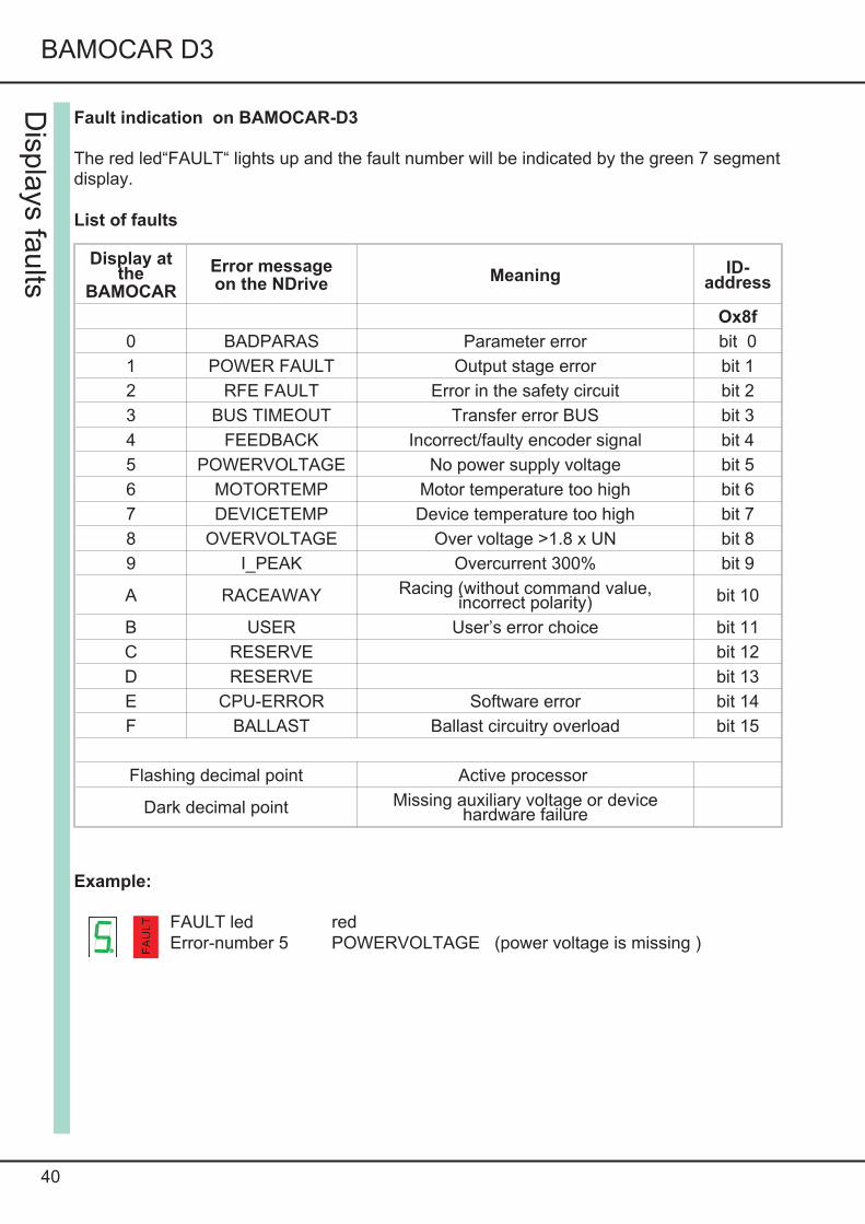
Fault indication on BAMOCAR-D3
The red led“FAULT“ lights up and the fault number will be indicated by the green 7 segmentdisplay.
List of faults
Display atthe
BAMOCAR
Error messageon the NDrive
Meaning ID-address
Ox8f
0 BADPARAS Parameter error bit 0
1 POWER FAULT Output stage error bit 1
2 RFE FAULT Error in the safety circuit bit 2
3 BUS TIMEOUT Transfer error BUS bit 3
4 FEEDBACK Incorrect/faulty encoder signal bit 4
5 POWERVOLTAGE No power supply voltage bit 5
6 MOTORTEMP Motor temperature too high bit 6
7 DEVICETEMP Device temperature too high bit 7
8 OVERVOLTAGE Over voltage >1.8 x UN bit 8
9 I_PEAK Overcurrent 300% bit 9
A RACEAWAY Racing (without command value,incorrect polarity) bit 10
B USER User’s error choice bit 11
C RESERVE bit 12
D RESERVE bit 13
E CPU-ERROR Software error bit 14
F BALLAST Ballast circuitry overload bit 15
Flashing decimal point Active processor
Dark decimal point Missing auxiliary voltage or devicehardware failure
Example:
FAULT led redError-number 5 POWERVOLTAGE (power voltage is missing )
Disp
lays
faults
FAUL
T
41
Electrical Installation
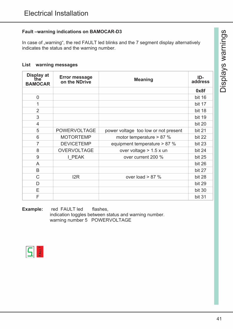
Fault –warning indications on BAMOCAR-D3
In case of „warning“, the red FAULT led blinks and the 7 segment display alternativelyindicates the status and the warning number.
List warning messages
Display atthe
BAMOCAR
Error messageon the NDrive
Meaning ID-address
0x8f
0 bit 16
1 bit 17
2 bit 18
3 bit 19
4 bit 20
5 POWERVOLTAGE power voltage too low or not present bit 21
6 MOTORTEMP motor temperature > 87 % bit 22
7 DEVICETEMP equipment temperature > 87 % bit 23
8 OVERVOLTAGE over voltage > 1.5 x un bit 24
9 I_PEAK over current 200 % bit 25
A bit 26
B bit 27
C I2R over load > 87 % bit 28
D bit 29
E bit 30
F bit 31
Example: red FAULT led flashes,indication toggles between status and warning number.warning number 5 POWERVOLTAGE
Dis
pla
ysw
arn
ings
FAUL
T
42
BAMOCAR D3
Measu
rem
ent
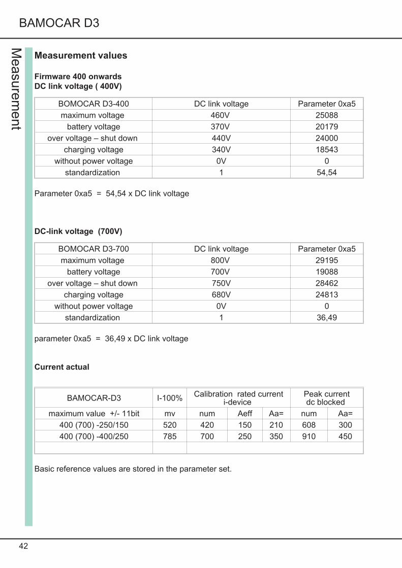
Measurement values
Firmware 400 onwards
DC link voltage ( 400V)
BOMOCAR D3-400 DC link voltage Parameter 0xa5
maximum voltage 460V 25088
battery voltage 370V 20179
over voltage – shut down 440V 24000
charging voltage 340V 18543
without power voltage 0V 0
standardization 1 54,54
Parameter 0xa5 = 54,54 x DC link voltage
DC-link voltage (700V)
BOMOCAR D3-700 DC link voltage Parameter 0xa5
maximum voltage 800V 29195
battery voltage 700V 19088
over voltage – shut down 750V 28462
charging voltage 680V 24813
without power voltage 0V 0
standardization 1 36,49
parameter 0xa5 = 36,49 x DC link voltage
Current actual
BAMOCAR-D3 I-100% Calibration rated currenti-device
Peak currentdc blocked
maximum value +/- 11bit mv num Aeff Aa= num Aa=
400 (700) -250/150 520 420 150 210 608 300
400 (700) -400/250 785 700 250 350 910 450
Basic reference values are stored in the parameter set.

43
Electrical Installation
Stage-temperature
IGBT temperature parameter 0x4a
maximal +83 24000 (FW>400)
Air-temperature
-20 -10 0 10 20 30 40 50 60 70 80
9000
10000
11000
12000
13000
14000
We
rtv
on
0x
4b
(Nu
m)
Luft- Temperatur ( C)o
Va
lue
of
0x
4b
(Nu
m)
Air- Temperature ( C)o
Measu
rem
ent
BAMOCAR
NTC
Stage- Temperature ( C)
Valu
eof
0x4a
(Num
)W
ert
von
0x4a
(Num
)W
ert
von
0x4a
(Num
)
Endstufen- Temperatur ( C)
Wert
von
0x4a
(Num
)
26000
24000
100
22000
20000
9020
18000
80
o
7010-20 60500
o40
32000
30000
28000
16000
30-10
44
BAMOCAR D3
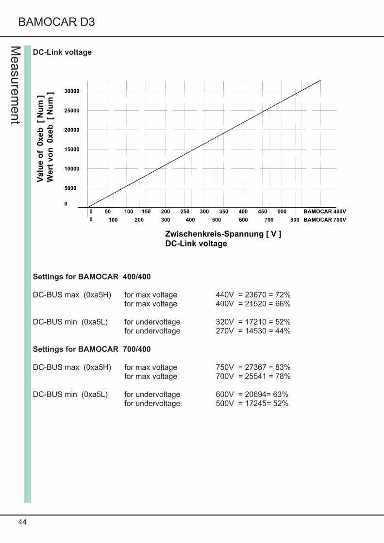
DC-Link voltage
Settings for BAMOCAR 400/400
DC-BUS max (0xa5H) for max voltage 440V = 23670 = 72%for max voltage 400V = 21520 = 66%
DC-BUS min (0xa5L) for undervoltage 320V = 17210 = 52%for undervoltage 270V = 14530 = 44%
Settings for BAMOCAR 700/400
DC-BUS max (0xa5H) for max voltage 750V = 27367 = 83%for max voltage 700V = 25541 = 78%
DC-BUS min (0xa5L) for undervoltage 600V = 20694= 63%for undervoltage 500V = 17245= 52%
Measu
rem
ent
0 50 100 150 200 250 300 350 400 450 500
0
5000
10000
15000
20000
25000
30000
Wert
vo
n0
xe
b[
Nu
m]
Zwischenkreis-Spannung [ V ]
100 200 300 400 500 600 700
BAMOCAR 400V
BAMOCAR 700V
Valu
eo
f0
xe
b[
Nu
m]
DC-Link voltage
8000
45
Electrical Installation
46
Guarentee
GuarenteeUNITEK guarantees that the equipment is free from material and manufacturing defects.The pre and post inspection values are archived along with the serial numbers of theequipments.
He guarantee period begins from the date of equipment delivery and extends up to twoyears.
UNITEK does not guarantee suitability of the equipment for any kind of specialapplications.
In case of defects in delivery, including non-availability of assured features, the liability ofUNITEK is only free of charge rectification, if sent to the manufacturer’s works or would bereplaced if necessary.
This liability of defects is void, when repair and maintenance is done in an improper way bythe customer or a third party, when defects arise due to the non observance of the suppliedmanual, non observance of electrical rules and regulations, due to improper handling or dueto natural calamities.
Consequential damages : all further claims of conversion, reduction and replacement ofdamages of any kind, especially damages, which are not caused at UNITEK equipmentsare ruled out.
Consequential damages, which arise due to the malfunctions or equipment fault in themachines or installation cannot be made valid. this is invalid insofar, as it is made legallycompulsory.
Manual instructionChanges in information contained in this manual are subject to change without notice.
All information pertaining to connection are general information and are non-binding. locallegal regulations and provision of standards are applicable.
UNITEK assumes no implicit or explicit liability of any kind, for product informationmentioned in this manual, neither for their functionality , nor for their suitability for specialapplications.
All rights reserved.
Reproduction , circulation and translation are allowed , provided all liabilities of UNITEKare excluded .
Guare
nte
e