Research Article Modiolus-Hugging Intracochlear Electrode...
10
Hindawi Publishing Corporation Computational and Mathematical Methods in Medicine Volume 2013, Article ID 250915, 9 pages http://dx.doi.org/10.1155/2013/250915 Research Article Modiolus-Hugging Intracochlear Electrode Array with Shape Memory Alloy Kyou Sik Min, 1 Sang Beom Jun, 2,3 Yoon Seob Lim, 1,4 Se-Ik Park, 1 and Sung June Kim 1 1 School of Electrical Engineering & Computer Science, Seoul National University, 1 Gwanak-ro, Gwanak-gu, Seoul 110-742, Republic of Korea 2 Department of Electronics Engineering, Ewha Womans University, 52 Ewhayeodae-gil, Seodaemun-gu, Seoul 120-750, Republic of Korea 3 Department of Brain & Cognitive Sciences, Ewha Womans University, 52 Ewhayeodae-gil, Seodaemun-gu, Seoul 120-750, Republic of Korea 4 Cognitive and Neural Systems, Boston University, 677 Beacon Street, Boston, MA 02215, USA Correspondence should be addressed to Sang Beom Jun; [email protected] Received 11 February 2013; Revised 15 April 2013; Accepted 15 April 2013 Academic Editor: Chang-Hwan Im Copyright © 2013 Kyou Sik Min et al. is is an open access article distributed under the Creative Commons Attribution License, which permits unrestricted use, distribution, and reproduction in any medium, provided the original work is properly cited. In the cochlear implant system, the distance between spiral ganglia and the electrodes within the volume of the scala tympani cavity significantly affects the efficiency of the electrical stimulation in terms of the threshold current level and spatial selectivity. Because the spiral ganglia are situated inside the modiolus, the central axis of the cochlea, it is desirable that the electrode array hugs the modiolus to minimize the distance between the electrodes and the ganglia. In the present study, we propose a shape-memory-alloy- (SMA-) embedded intracochlear electrode which gives a straight electrode a curved modiolus-hugging shape using the restoration force of the SMA as triggered by resistive heating aſter insertion into the cochlea. An eight-channel ball-type electrode array is fabricated with an embedded titanium-nickel SMA backbone wire. It is demonstrated that the electrode array changes its shape in a transparent plastic human cochlear model. To verify the safe insertion of the electrode array into the human cochlea, the contact pressures during insertion at the electrode tip and the contact pressures over the electrode length aſter insertion were calculated using a 3D finite element analysis. e results indicate that the SMA-embedded electrode is functionally and mechanically feasible for clinical applications. 1. Introduction During the past several decades, cochlear implant systems have been established as a successful treatment for people suffering from severe hearing impairment due to hair cell loss. In general, a cochlear implant system consists of a multichan- nel intracochlear electrode, electronics in a hermetic package, and an external speech processor with a signal and power transmission coil. Briefly, the system converts sound signals into electrical signals and divides into multiple channels with different frequencies at the external speech processor. ese signals then are radio-frequency- (RF-) modulated and transferred to the receiver/stimulator ASIC chip in a hermetic package through a transcutaneous coil link. Aſter demodulation, the signals generate stimulating current pulses for each channel. rough the intracochlear electrode array, the current pulses stimulate ganglion cells in the inner ear, inducing auditory sensations in the recipients. e most important parts of the functionality of a cochlear implant are design of electrode array. Todays, insertion of a cochlear electrode array becomes far more important because it is required that newly developed electrode array can preserve residual hearing, be inserted deeper region of scala tympani, and stimulate targets more efficiently [1]. One of the challenges to improve the current cochlear implant system is to realize spatially high-resolution electrical stimulation to restore sound perception close to normal hearing. To achieve this goal, it is essential to locate the intracochlear electrode array close to the spiral ganglia, the target of the electrical stimulation, because the current will
Transcript of Research Article Modiolus-Hugging Intracochlear Electrode...
Hindawi Publishing CorporationComputational and Mathematical Methods in MedicineVolume 2013, Article ID 250915, 9 pageshttp://dx.doi.org/10.1155/2013/250915
Research ArticleModiolus-Hugging Intracochlear Electrode Array withShape Memory Alloy
Kyou Sik Min,1 Sang Beom Jun,2,3 Yoon Seob Lim,1,4 Se-Ik Park,1 and Sung June Kim1
1 School of Electrical Engineering & Computer Science, Seoul National University, 1 Gwanak-ro, Gwanak-gu,Seoul 110-742, Republic of Korea
2Department of Electronics Engineering, Ewha Womans University, 52 Ewhayeodae-gil, Seodaemun-gu,Seoul 120-750, Republic of Korea
3 Department of Brain & Cognitive Sciences, Ewha Womans University, 52 Ewhayeodae-gil, Seodaemun-gu,Seoul 120-750, Republic of Korea
4Cognitive and Neural Systems, Boston University, 677 Beacon Street, Boston, MA 02215, USA
Correspondence should be addressed to Sang Beom Jun; [email protected]
Received 11 February 2013; Revised 15 April 2013; Accepted 15 April 2013
Academic Editor: Chang-Hwan Im
Copyright © 2013 Kyou Sik Min et al. This is an open access article distributed under the Creative Commons Attribution License,which permits unrestricted use, distribution, and reproduction in any medium, provided the original work is properly cited.
In the cochlear implant system, the distance between spiral ganglia and the electrodes within the volume of the scala tympani cavitysignificantly affects the efficiency of the electrical stimulation in terms of the threshold current level and spatial selectivity. Becausethe spiral ganglia are situated inside the modiolus, the central axis of the cochlea, it is desirable that the electrode array hugs themodiolus tominimize the distance between the electrodes and the ganglia. In the present study, we propose a shape-memory-alloy-(SMA-) embedded intracochlear electrode which gives a straight electrode a curved modiolus-hugging shape using the restorationforce of the SMA as triggered by resistive heating after insertion into the cochlea. An eight-channel ball-type electrode array isfabricated with an embedded titanium-nickel SMA backbone wire. It is demonstrated that the electrode array changes its shape ina transparent plastic human cochlear model. To verify the safe insertion of the electrode array into the human cochlea, the contactpressures during insertion at the electrode tip and the contact pressures over the electrode length after insertion were calculatedusing a 3D finite element analysis. The results indicate that the SMA-embedded electrode is functionally and mechanically feasiblefor clinical applications.
1. Introduction
During the past several decades, cochlear implant systemshave been established as a successful treatment for peoplesuffering from severe hearing impairment due to hair cell loss.In general, a cochlear implant system consists of amultichan-nel intracochlear electrode, electronics in a hermetic package,and an external speech processor with a signal and powertransmission coil. Briefly, the system converts sound signalsinto electrical signals and divides into multiple channelswith different frequencies at the external speech processor.These signals then are radio-frequency- (RF-) modulatedand transferred to the receiver/stimulator ASIC chip in ahermetic package through a transcutaneous coil link. Afterdemodulation, the signals generate stimulating current pulses
for each channel. Through the intracochlear electrode array,the current pulses stimulate ganglion cells in the inner ear,inducing auditory sensations in the recipients. The mostimportant parts of the functionality of a cochlear implantare design of electrode array. Todays, insertion of a cochlearelectrode array becomes far more important because it isrequired that newly developed electrode array can preserveresidual hearing, be inserted deeper region of scala tympani,and stimulate targets more efficiently [1].
One of the challenges to improve the current cochlearimplant system is to realize spatially high-resolution electricalstimulation to restore sound perception close to normalhearing. To achieve this goal, it is essential to locate theintracochlear electrode array close to the spiral ganglia, thetarget of the electrical stimulation, because the current will
2 Computational and Mathematical Methods in Medicine
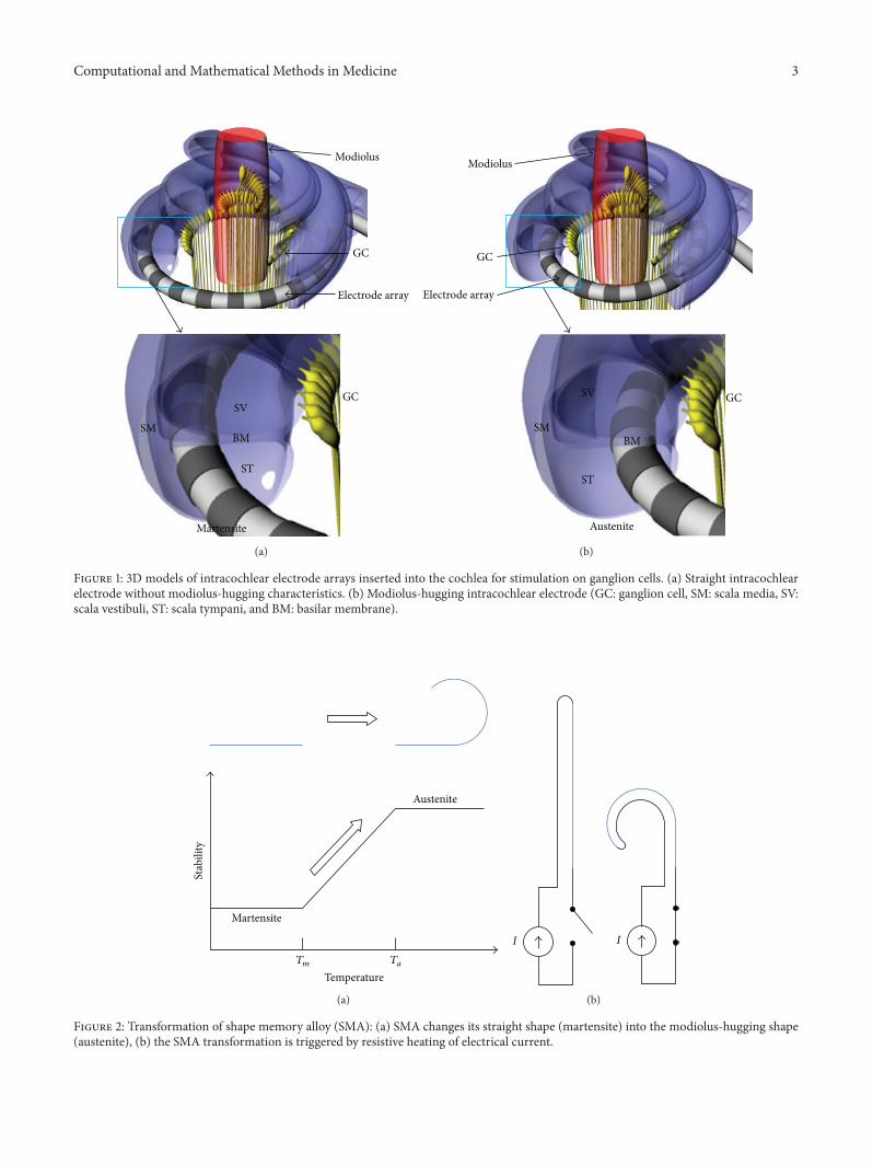
diffuse and stimulate a large number of ganglia with lowspecificity if the electrode is located far from the target cells.In general, the electrode of a cochlear implant is inserted intothe scala tympani because it has the largest cross-sectionalarea and an easy surgical operation site as shown in Figure 1.Stimulating currents flowing from the electrode site stimulatethe ganglion cells located in the direction of the cochlearmodiolus. Therefore, it is desired that the electrode is locatedclose to the modiolus, as depicted in Figure 1(b), to reducethe distance between the electrode and the ganglia andincrease the spatial specificity of the electrical stimulation [2].When implanting the electrode array into the scala tympani,however, a straight shape is desirable to facilitate insertion bysurgeons. If the electrode array is straight after molding withelastic silicon rubber, the electrode array is located along withthe outer wall radius of the scala tympani due to the elasticrestoration force of the electrode (Figure 1(a)).
Several strategies have been developed and employed forcommercial cochlear implant systems to locate the electrodeclose to the modiolus. Advanced Bionics, Inc. and CochlearLtd. have developed modiolus-hugging electrodes using apreformed carrier which is held straight by an internal styletbefore and during the insertion process [3]. After the partialinsertion of the electrode and stylet, the electrode is pushedto its full insertion depth while holding the stylet at the sameposition. The electrode returns to its original spiral shapewhile being pushed toward the modiolus [4, 5]. Accordingly,the insertion depth of the stylet is critical in modiolus-hugging electrode array surgery. If the stylet is inserted fardeeper into the cochleostomy, the electrode tip will come intocontact with the cochlear outer wall, which may damage thespiral ligament or penetrate into the scala vestibuli. On theother hand, if the insertion depth of the stylet is too short,the apical curve of the electrode will curl before the firstturn of the scala tympani [6]. Another method for modiolus-hugging was to insert an additional silastic structure calleda positioner along the outside of the electrode after itsinsertion. The positioner pushes the electrode toward themodiolus, which locates the electrode sites in the vicinityof the ganglion cells [7]. However, when using this method,surgeons must undertake a precise insertion process twice.In addition, it was reported that the enlarged hole for theadditional insertion of the positioner can cause meningitis[8].
In order to overcome these disadvantages, it was proposedto make the stylet with shape memory alloy (SMA), whichconverts its initial straight shape into a curved shape at thebody temperature [9]. With this method, the electrode hugsthe modiolus once it is inserted into the scala tympani by therestoration force of SMA stylets, during which the modiolus-hugging shape is memorized. However, it is not easy to pullout the electrode or to reinsert it once it is inserted becausethe SMA force always exists at the temperature of the humanbody. The heat from the surgeon’s hands may also triggerSMA transformation before the insertion of the electrode.
In the present study, we propose an intracochlear elec-trode embedded with SMA without the drawbacks relatedto the transition temperature of the human body. Similarto the previous method, the SMA is pretreated to have
a modiolus-hugging shape above its transition temperature.However, because the SMA is transformed into itsmemorizedshape slightly above the body temperature, the electrode canbe handled by a surgeon without SMA transformation duringthe insertion process. The transformation into the modiolus-hugging shape can be controlled by heating via an electricalcurrent to the SMA after the insertion. We developed aneight-channel intracochlear electrode in which SMA wire isembedded. A finite element analysis was performed to verifythe mechanical safety of the electrode array compared withconventional electrode arrays.
2. Materials and Methods
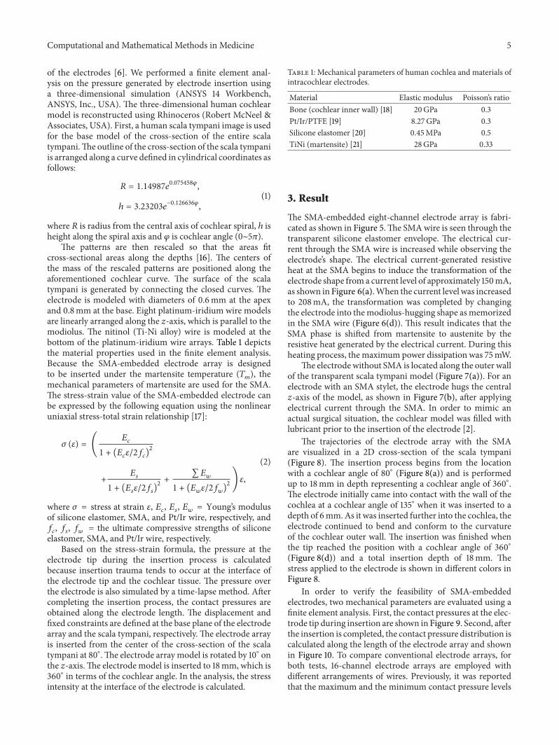
2.1. Shape Memory Alloy. The shape memory alloy (SMA)has two different phases: martensite and austenite.Martensiteis the relatively soft and easily deformable phase of shapememory alloys, and it exists at a lower temperature. Austenite,the stronger phase of shape memory alloys, occurs at highertemperatures. Above a specific temperature, the deformedSMA in martensite is transformed into the austenite phase,which is configured as the original shape of the wire. Thetemperatures at which the transformation begins and endsare defined as𝑇
𝑚and𝑇𝑎(Figure 2), respectively. In this study,
𝑇𝑚is defined as higher than the temperature of the human
body in order to prevent the SMA from being transformed byheat from the surgeon’s hands or by the patient’s body whileinserting the electrode into the cochlear scala tympani. 𝑇
𝑎is
defined as low as possible so as not to cause tissue damageby the heat generated from the SMA. Using titanium-nickelalloy, the SMA is prepared such that𝑇
𝑚is 40∘C and𝑇
𝑎is 45∘C
(Jin-Sung Ltd., Eui Wang, Korea).The human cochlear canal is a spiral structure with 2.5
turns. If straightened, its length is approximately 32mmfrom the base to the apex of the cochlea. However, themaximum insertion angle of the intracochlear electrodes isusually 360∘ and less than 25mm in length, as shown in themodeling result of the trace of the electrode tip in Figure 3.In Figure 3(b), the smallest radius of curvature of the traceis 2.38mm. To simplify the fabrication of SMA wires tobe embedded in electrodes, the displacement on the 𝑧-axis(0.336mm)was ignored because it ismuch smaller than thoseof the 𝑥- and 𝑦-axes, as depicted in Figure 3. The SMA wires(0.1mm diameter) were fabricated in the shape of a springwhose curvature is 4.7mm in diameter so that it can ensurethat the curvature hugs the modiolus. The SMA spring wascut to have a length of 15mm and an angle of 360∘.
2.2. Electrode Fabrication and Transformation Test. An eight-channel intracochlear electrode array was fabricated. Inthis process, the ball-shaped sites are made from Teflon-coated 25 𝜇m (dia.) 90% Pt/10% Ir-alloy wire (A-M systems,Inc., USA) by melting the wire with an oxygen/acetyleneminitorch. The diameter of the ball sites is 420 𝜇m.The ballsare fixed at a hole in the bottommold, as depicted in Figure 4,using silicone elastomer MED 4211 (Nusil, Ltd., USA). Bothends of the SMA wire are soldered with the same wires asthe electrodes. The SMA wire is straightened and is then
Computational and Mathematical Methods in Medicine 3
GC
SM
ST
BM
SV
Martensite
GC
Modiolus
Electrode array
(a)
GC
SM
SV
BM
ST
Austenite
GC
Electrode array
Modiolus
(b)
Figure 1: 3D models of intracochlear electrode arrays inserted into the cochlea for stimulation on ganglion cells. (a) Straight intracochlearelectrode without modiolus-hugging characteristics. (b) Modiolus-hugging intracochlear electrode (GC: ganglion cell, SM: scala media, SV:scala vestibuli, ST: scala tympani, and BM: basilar membrane).
Stab
ility
Austenite
Martensite
Temperature𝑇𝑚 𝑇𝑎
(a)
𝐼 𝐼
(b)
Figure 2: Transformation of shape memory alloy (SMA): (a) SMA changes its straight shape (martensite) into the modiolus-hugging shape(austenite), (b) the SMA transformation is triggered by resistive heating of electrical current.

4 Computational and Mathematical Methods in Medicine
0.5
0.4
0.3
0.2
0.1
0
−4
−2
−2
00
2
2
−4
Base
(a)
2
0
−2
−4
20−2−4
2.38mm
(b)
Figure 3: Trace of electrode tip during the insertion into scala tympani of human cochlea (all units are mm in this picture): (a) 3D trajectoryof the electrode tip and (b) the trajectory of the electrode tip projected on 𝑥-𝑦 plane.
Mold
Teflon-insulatedPt/Ir wire with ball sites
Silicone elastomer
(a)
Pt/Ir wires withball-type sites SMA wire
Pt/Ir wires
Bottom mold Top mold
Siliconeelastomer
(b)
Figure 4: Fabrication of the SMA-embedded ball-type intracochlear electrode: (a) ball site fixation at a hole in the bottom mold and (b)fixation of eight-channel ball electrodes and the SMA wire at bottom and top molds, respectively.
fixed at the top mold with the elastomer. After joining twomolds, degassed silicone elastomer is injected into the inlet.To prevent the SMA from being transformed, the elastomeris cured at room temperature for 2 days and then at 150∘Cfor 30 minutes to complete the curing. The distance betweenadjacent sites is 1.8mm.The total length of the electrode to beinserted into the cochlea is 21.5mm.The electrode diameterswere 0.6mm at the apex and 0.8mm at the base.
To determine if the fabricated SMA-embedded elec-trode array is transformed into the modiolus-hugging shape,various amplitudes of electrical current are applied to wiresconnected to both ends of the SMA. The electrode isalso inserted into a clear human cochlear model, and therestoration force of the SMA triggered by resistive heating isapplied to verify that the electrode can change its shape intoa modiolus-hugging shape.
Figure 5: Eight-channel SMA-embedded intracochlear electrodearray (scale bar: 2mm).
2.3. Electrode Insertion Simulation. It was reported that theinsertion of a cochlear electrode may cause trauma at thebasilar membrane, which is very thin and soft [10–12].Researchers inserted electrodes into the cochleae of humancadavers or the cochleae of animals in an effort to provethe mechanical safety of the electrodes [13–15]. It is alsoknown that the trauma can be predicted by the stiffness
Computational and Mathematical Methods in Medicine 5
of the electrodes [6]. We performed a finite element anal-ysis on the pressure generated by electrode insertion usinga three-dimensional simulation (ANSYS 14 Workbench,ANSYS, Inc., USA). The three-dimensional human cochlearmodel is reconstructed using Rhinoceros (Robert McNeel &Associates, USA). First, a human scala tympani image is usedfor the base model of the cross-section of the entire scalatympani.The outline of the cross-section of the scala tympaniis arranged along a curve defined in cylindrical coordinates asfollows:
𝑅 = 1.14987𝑒0.075458𝜑
,
ℎ = 3.23203𝑒−0.126636𝜑
,
(1)
where 𝑅 is radius from the central axis of cochlear spiral, ℎ isheight along the spiral axis and 𝜑 is cochlear angle (0∼5𝜋).
The patterns are then rescaled so that the areas fitcross-sectional areas along the depths [16]. The centers ofthe mass of the rescaled patterns are positioned along theaforementioned cochlear curve. The surface of the scalatympani is generated by connecting the closed curves. Theelectrode is modeled with diameters of 0.6mm at the apexand 0.8mm at the base. Eight platinum-iridium wire modelsare linearly arranged along the 𝑧-axis, which is parallel to themodiolus. The nitinol (Ti-Ni alloy) wire is modeled at thebottom of the platinum-iridium wire arrays. Table 1 depictsthe material properties used in the finite element analysis.Because the SMA-embedded electrode array is designedto be inserted under the martensite temperature (𝑇
𝑚), the
mechanical parameters of martensite are used for the SMA.The stress-strain value of the SMA-embedded electrode canbe expressed by the following equation using the nonlinearuniaxial stress-total strain relationship [17]:
𝜎 (𝜀) = (𝐸𝑐
1 + (𝐸𝑐𝜀/2𝑓𝑐)2
+𝐸𝑠
1 + (𝐸𝑠𝜀/2𝑓𝑠)2+∑𝐸𝑤
1 + (𝐸𝑤𝜀/2𝑓𝑤)2)𝜀,
(2)
where 𝜎 = stress at strain 𝜀, 𝐸𝑐, 𝐸𝑠, 𝐸𝑤= Young’s modulus
of silicone elastomer, SMA, and Pt/Ir wire, respectively, and𝑓𝑐, 𝑓𝑠, 𝑓𝑤= the ultimate compressive strengths of silicone
elastomer, SMA, and Pt/Ir wire, respectively.Based on the stress-strain formula, the pressure at the
electrode tip during the insertion process is calculatedbecause insertion trauma tends to occur at the interface ofthe electrode tip and the cochlear tissue. The pressure overthe electrode is also simulated by a time-lapse method. Aftercompleting the insertion process, the contact pressures areobtained along the electrode length. The displacement andfixed constraints are defined at the base plane of the electrodearray and the scala tympani, respectively. The electrode arrayis inserted from the center of the cross-section of the scalatympani at 80∘.The electrode array model is rotated by 10∘ onthe 𝑧-axis.The electrodemodel is inserted to 18mm, which is360∘ in terms of the cochlear angle. In the analysis, the stressintensity at the interface of the electrode is calculated.
Table 1: Mechanical parameters of human cochlea and materials ofintracochlear electrodes.
Material Elastic modulus Poisson’s ratioBone (cochlear inner wall) [18] 20GPa 0.3Pt/Ir/PTFE [19] 8.27GPa 0.3Silicone elastomer [20] 0.45MPa 0.5TiNi (martensite) [21] 28GPa 0.33
3. Result
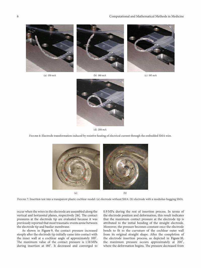
The SMA-embedded eight-channel electrode array is fabri-cated as shown in Figure 5.The SMAwire is seen through thetransparent silicone elastomer envelope. The electrical cur-rent through the SMA wire is increased while observing theelectrode’s shape. The electrical current-generated resistiveheat at the SMA begins to induce the transformation of theelectrode shape froma current level of approximately 150mA,as shown in Figure 6(a).When the current level was increasedto 208mA, the transformation was completed by changingthe electrode into themodiolus-hugging shape asmemorizedin the SMA wire (Figure 6(d)). This result indicates that theSMA phase is shifted from martensite to austenite by theresistive heat generated by the electrical current. During thisheating process, the maximum power dissipation was 75mW.
The electrode without SMA is located along the outer wallof the transparent scala tympani model (Figure 7(a)). For anelectrode with an SMA stylet, the electrode hugs the central𝑧-axis of the model, as shown in Figure 7(b), after applyingelectrical current through the SMA. In order to mimic anactual surgical situation, the cochlear model was filled withlubricant prior to the insertion of the electrode [2].
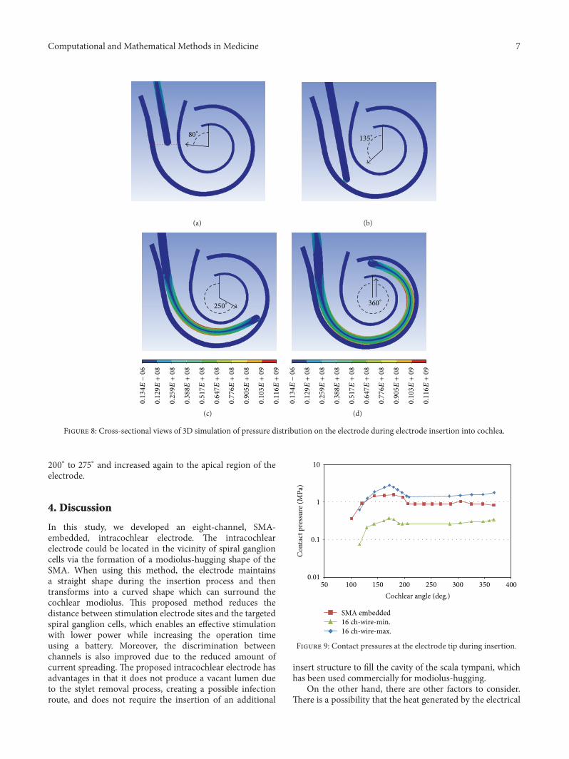
The trajectories of the electrode array with the SMAare visualized in a 2D cross-section of the scala tympani(Figure 8). The insertion process begins from the locationwith a cochlear angle of 80∘ (Figure 8(a)) and is performedup to 18mm in depth representing a cochlear angle of 360∘.The electrode initially came into contact with the wall of thecochlea at a cochlear angle of 135∘ when it was inserted to adepth of 6mm.As it was inserted further into the cochlea, theelectrode continued to bend and conform to the curvatureof the cochlear outer wall. The insertion was finished whenthe tip reached the position with a cochlear angle of 360∘(Figure 8(d)) and a total insertion depth of 18mm. Thestress applied to the electrode is shown in different colors inFigure 8.
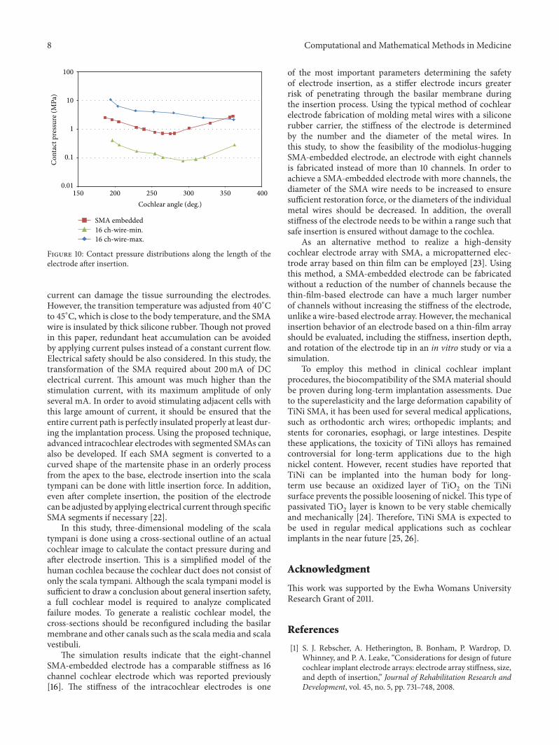
In order to verify the feasibility of SMA-embeddedelectrodes, two mechanical parameters are evaluated using afinite element analysis. First, the contact pressures at the elec-trode tip during insertion are shown in Figure 9. Second, afterthe insertion is completed, the contact pressure distribution iscalculated along the length of the electrode array and shownin Figure 10. To compare conventional electrode arrays, forboth tests, 16-channel electrode arrays are employed withdifferent arrangements of wires. Previously, it was reportedthat the maximum and the minimum contact pressure levels
6 Computational and Mathematical Methods in Medicine
(a) 150 mA (b) 180 mA (c) 195 mA
(d) 200 mA
Figure 6: Electrode transformation induced by resistive heating of electrical current through the embedded SMA wire.
(a) (b)
Figure 7: Insertion test into a transparent plastic cochlear model: (a) electrode without SMA: (b) electrode with a modiolus-hugging SMA.
occur when the wires in the electrode are assembled along thevertical and horizontal planes, respectively [16]. The contactpressures at the electrode tip are evaluated because it waspreviously reported thatmost traumatic events arose betweenthe electrode tip and basilar membrane.
As shown in Figure 9, the contact pressure increasedsteeply after the electrode tip initially came into contact withthe inner wall at a cochlear angle of approximately 100∘.The maximum value of the contact pressure is 1.58MPaduring insertion at 180∘. It decreased and converged to
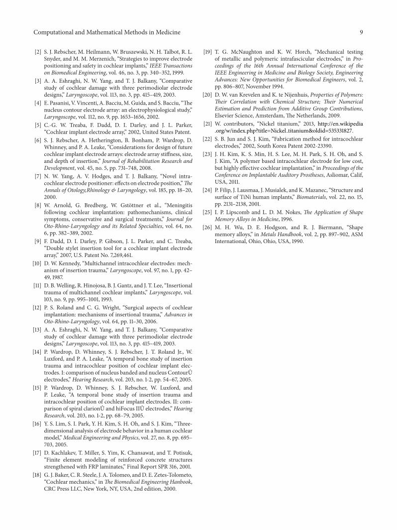
0.9MPa during the rest of insertion process. In terms ofthe electrode position and deformation, this result indicatesthat the maximum contact pressure at the electrode tip isattributed to the initial bending of the straight electrode.Moreover, the pressure becomes constant once the electrodebends to fit to the curvature of the cochlear outer wallfrom its original straight shape. After the completion ofthe electrode insertion process, as depicted in Figure 10,the maximum pressure occurs approximately at 200∘,where the deformation begins. The pressure decreased from
Computational and Mathematical Methods in Medicine 7
80∘
(a)
135∘
(b)
250∘
0.134𝐸−06
0.129𝐸+08
0.259𝐸+08
0.388𝐸+08
0.517𝐸+08
0.647𝐸+08
0.776𝐸+08
0.905𝐸+08
0.103𝐸+09
0.116𝐸+09
(c)
360∘
0.134𝐸−06
0.129𝐸+08
0.259𝐸+08
0.388𝐸+08
0.517𝐸+08
0.647𝐸+08
0.776𝐸+08
0.905𝐸+08
0.103𝐸+09
0.116𝐸+09
(d)
Figure 8: Cross-sectional views of 3D simulation of pressure distribution on the electrode during electrode insertion into cochlea.
200∘ to 275∘ and increased again to the apical region of theelectrode.
4. Discussion
In this study, we developed an eight-channel, SMA-embedded, intracochlear electrode. The intracochlearelectrode could be located in the vicinity of spiral ganglioncells via the formation of a modiolus-hugging shape of theSMA. When using this method, the electrode maintainsa straight shape during the insertion process and thentransforms into a curved shape which can surround thecochlear modiolus. This proposed method reduces thedistance between stimulation electrode sites and the targetedspiral ganglion cells, which enables an effective stimulationwith lower power while increasing the operation timeusing a battery. Moreover, the discrimination betweenchannels is also improved due to the reduced amount ofcurrent spreading. The proposed intracochlear electrode hasadvantages in that it does not produce a vacant lumen dueto the stylet removal process, creating a possible infectionroute, and does not require the insertion of an additional
0.01
0.1
1
10
50 100 150 200 250 300 350 400
SMA embedded
Con
tact
pre
ssur
e (M
Pa)
Cochlear angle (deg.)
16 ch-wire-min.16 ch-wire-max.
Figure 9: Contact pressures at the electrode tip during insertion.
insert structure to fill the cavity of the scala tympani, whichhas been used commercially for modiolus-hugging.
On the other hand, there are other factors to consider.There is a possibility that the heat generated by the electrical
8 Computational and Mathematical Methods in Medicine
0.01
0.1
1
10
100
150 200 250 300 350 400
SMA embedded
Con
tact
pre
ssur
e (M
Pa)
Cochlear angle (deg.)
16 ch-wire-min.16 ch-wire-max.
Figure 10: Contact pressure distributions along the length of theelectrode after insertion.
current can damage the tissue surrounding the electrodes.However, the transition temperature was adjusted from 40∘Cto 45∘C, which is close to the body temperature, and the SMAwire is insulated by thick silicone rubber. Though not provedin this paper, redundant heat accumulation can be avoidedby applying current pulses instead of a constant current flow.Electrical safety should be also considered. In this study, thetransformation of the SMA required about 200mA of DCelectrical current. This amount was much higher than thestimulation current, with its maximum amplitude of onlyseveral mA. In order to avoid stimulating adjacent cells withthis large amount of current, it should be ensured that theentire current path is perfectly insulated properly at least dur-ing the implantation process. Using the proposed technique,advanced intracochlear electrodes with segmented SMAs canalso be developed. If each SMA segment is converted to acurved shape of the martensite phase in an orderly processfrom the apex to the base, electrode insertion into the scalatympani can be done with little insertion force. In addition,even after complete insertion, the position of the electrodecan be adjusted by applying electrical current through specificSMA segments if necessary [22].
In this study, three-dimensional modeling of the scalatympani is done using a cross-sectional outline of an actualcochlear image to calculate the contact pressure during andafter electrode insertion. This is a simplified model of thehuman cochlea because the cochlear duct does not consist ofonly the scala tympani. Although the scala tympani model issufficient to draw a conclusion about general insertion safety,a full cochlear model is required to analyze complicatedfailure modes. To generate a realistic cochlear model, thecross-sections should be reconfigured including the basilarmembrane and other canals such as the scala media and scalavestibuli.
The simulation results indicate that the eight-channelSMA-embedded electrode has a comparable stiffness as 16channel cochlear electrode which was reported previously[16]. The stiffness of the intracochlear electrodes is one
of the most important parameters determining the safetyof electrode insertion, as a stiffer electrode incurs greaterrisk of penetrating through the basilar membrane duringthe insertion process. Using the typical method of cochlearelectrode fabrication of molding metal wires with a siliconerubber carrier, the stiffness of the electrode is determinedby the number and the diameter of the metal wires. Inthis study, to show the feasibility of the modiolus-huggingSMA-embedded electrode, an electrode with eight channelsis fabricated instead of more than 10 channels. In order toachieve a SMA-embedded electrode with more channels, thediameter of the SMA wire needs to be increased to ensuresufficient restoration force, or the diameters of the individualmetal wires should be decreased. In addition, the overallstiffness of the electrode needs to be within a range such thatsafe insertion is ensured without damage to the cochlea.
As an alternative method to realize a high-densitycochlear electrode array with SMA, a micropatterned elec-trode array based on thin film can be employed [23]. Usingthis method, a SMA-embedded electrode can be fabricatedwithout a reduction of the number of channels because thethin-film-based electrode can have a much larger numberof channels without increasing the stiffness of the electrode,unlike a wire-based electrode array. However, themechanicalinsertion behavior of an electrode based on a thin-film arrayshould be evaluated, including the stiffness, insertion depth,and rotation of the electrode tip in an in vitro study or via asimulation.
To employ this method in clinical cochlear implantprocedures, the biocompatibility of the SMAmaterial shouldbe proven during long-term implantation assessments. Dueto the superelasticity and the large deformation capability ofTiNi SMA, it has been used for several medical applications,such as orthodontic arch wires; orthopedic implants; andstents for coronaries, esophagi, or large intestines. Despitethese applications, the toxicity of TiNi alloys has remainedcontroversial for long-term applications due to the highnickel content. However, recent studies have reported thatTiNi can be implanted into the human body for long-term use because an oxidized layer of TiO
2on the TiNi
surface prevents the possible loosening of nickel. This type ofpassivated TiO
2layer is known to be very stable chemically
and mechanically [24]. Therefore, TiNi SMA is expected tobe used in regular medical applications such as cochlearimplants in the near future [25, 26].
Acknowledgment
This work was supported by the Ewha Womans UniversityResearch Grant of 2011.
References
[1] S. J. Rebscher, A. Hetherington, B. Bonham, P. Wardrop, D.Whinney, and P. A. Leake, “Considerations for design of futurecochlear implant electrode arrays: electrode array stiffness, size,and depth of insertion,” Journal of Rehabilitation Research andDevelopment, vol. 45, no. 5, pp. 731–748, 2008.
Computational and Mathematical Methods in Medicine 9
[2] S. J. Rebscher, M. Heilmann, W. Bruszewski, N. H. Talbot, R. L.Snyder, and M. M. Merzenich, “Strategies to improve electrodepositioning and safety in cochlear implants,” IEEE Transactionson Biomedical Engineering, vol. 46, no. 3, pp. 340–352, 1999.
[3] A. A. Eshraghi, N. W. Yang, and T. J. Balkany, “Comparativestudy of cochlear damage with three perimodiolar electrodedesigns,” Laryngoscope, vol. 113, no. 3, pp. 415–419, 2003.
[4] E. Pasanisi, V.Vincenti, A. Bacciu,M.Guida, and S. Bacciu, “Thenucleus contour electrode array: an electrophysiological study,”Laryngoscope, vol. 112, no. 9, pp. 1653–1656, 2002.
[5] C.-G. W. Treaba, F. Dadd, D. I. Darley, and J. L. Parker,“Cochlear implant electrode array,” 2002, United States Patent.
[6] S. J. Rebscher, A. Hetherington, B. Bonham, P. Wardrop, D.Whinney, and P. A. Leake, “Considerations for design of futurecochlear implant electrode arrays: electrode array stiffness, size,and depth of insertion,” Journal of Rehabilitation Research andDevelopment, vol. 45, no. 5, pp. 731–748, 2008.
[7] N. W. Yang, A. V. Hodges, and T. J. Balkany, “Novel intra-cochlear electrode positioner: effects on electrode position,”TheAnnals of Otology,Rhinology & Laryngology, vol. 185, pp. 18–20,2000.
[8] W. Arnold, G. Bredberg, W. Gstottner et al., “Meningitisfollowing cochlear implantation: pathomechanisms, clinicalsymptoms, conservative and surgical treatments,” Journal forOto-Rhino-Laryngology and its Related Specialties, vol. 64, no.6, pp. 382–389, 2002.
[9] F. Dadd, D. I. Darley, P. Gibson, J. L. Parker, and C. Treaba,“Double stylet insertion tool for a cochlear implant electrodearray,” 2007, U.S. Patent No. 7,269,461.
[10] D. W. Kennedy, “Multichannel intracochlear electrodes: mech-anism of insertion trauma,” Laryngoscope, vol. 97, no. 1, pp. 42–49, 1987.
[11] D. B.Welling, R. Hinojosa, B. J. Gantz, and J. T. Lee, “Insertionaltrauma of multichannel cochlear implants,” Laryngoscope, vol.103, no. 9, pp. 995–1001, 1993.
[12] P. S. Roland and C. G. Wright, “Surgical aspects of cochlearimplantation: mechanisms of insertional trauma,” Advances inOto-Rhino-Laryngology, vol. 64, pp. 11–30, 2006.
[13] A. A. Eshraghi, N. W. Yang, and T. J. Balkany, “Comparativestudy of cochlear damage with three perimodiolar electrodedesigns,” Laryngoscope, vol. 113, no. 3, pp. 415–419, 2003.
[14] P. Wardrop, D. Whinney, S. J. Rebscher, J. T. Roland Jr., W.Luxford, and P. A. Leake, “A temporal bone study of insertiontrauma and intracochlear position of cochlear implant elec-trodes. I: comparison of nucleus banded and nucleus ContourŮelectrodes,” Hearing Research, vol. 203, no. 1-2, pp. 54–67, 2005.
[15] P. Wardrop, D. Whinney, S. J. Rebscher, W. Luxford, andP. Leake, “A temporal bone study of insertion trauma andintracochlear position of cochlear implant electrodes. II: com-parison of spiral clarionŮ and hiFocus IIŮ electrodes,”HearingResearch, vol. 203, no. 1-2, pp. 68–79, 2005.
[16] Y. S. Lim, S. I. Park, Y. H. Kim, S. H. Oh, and S. J. Kim, “Three-dimensional analysis of electrode behavior in a human cochlearmodel,”Medical Engineering and Physics, vol. 27, no. 8, pp. 695–703, 2005.
[17] D. Kachlakev, T. Miller, S. Yim, K. Chansawat, and T. Potisuk,“Finite element modeling of reinforced concrete structuresstrengthened with FRP laminates,” Final Report SPR 316, 2001.
[18] G. J. Baker, C. R. Steele, J. A. Tolomeo, andD. E. Zetes-Tolometo,“Cochlear mechanics,” inThe Biomedical Engineering Hanbook,CRC Press LLC, New York, NY, USA, 2nd edition, 2000.
[19] T. G. McNaughton and K. W. Horch, “Mechanical testingof metallic and polymeric intrafascicular electrodes,” in Pro-ceedings of the 16th Annual International Conference of theIEEE Engineering in Medicine and Biology Society, EngineeringAdvances: New Opportunities for Biomedical Engineers, vol. 2,pp. 806–807, November 1994.
[20] D. W. van Krevelen and K. te Nijenhuis, Properties of Polymers:Their Correlation with Chemical Structure; Their NumericalEstimation and Prediction from Additive Group Contributions,Elsevier Science, Amsterdam, The Netherlands, 2009.
[21] W. contributors, “Nickel titanium,” 2013, http://en.wikipedia.org/w/index.php?title=Nickel titanium&oldid=535331827.
[22] S. B. Jun and S. J. Kim, “Fabrication method for intracochlearelectrodes,” 2002, South Korea Patent 2002-23390.
[23] J. H. Kim, K. S. Min, H. S. Lee, M. H. Park, S. H. Oh, and S.J. Kim, “A polymer based intracochlear electrode for low cost,but highly effective cochlear implantation,” in Proceedings of theConference on Implantable Auditory Prostheses, Asliomar, Calif,USA, 2011.
[24] P. Filip, J. Lausmaa, J. Musialek, and K.Mazanec, “Structure andsurface of TiNi human implants,” Biomaterials, vol. 22, no. 15,pp. 2131–2138, 2001.
[25] I. P. Lipscomb and L. D. M. Nokes, The Application of ShapeMemory Alloys in Medicine, 1996.
[26] M. H. Wu, D. E. Hodgson, and R. J. Biermann, “Shapememory alloys,” inMetals Handbook, vol. 2, pp. 897–902, ASMInternational, Ohio, Ohio, USA, 1990.

Submit your manuscripts athttp://www.hindawi.com
Stem CellsInternational
Hindawi Publishing Corporationhttp://www.hindawi.com Volume 2014
Hindawi Publishing Corporationhttp://www.hindawi.com Volume 2014
MEDIATORSINFLAMMATION
of
Hindawi Publishing Corporationhttp://www.hindawi.com Volume 2014
Behavioural Neurology
EndocrinologyInternational Journal of
Hindawi Publishing Corporationhttp://www.hindawi.com Volume 2014
Hindawi Publishing Corporationhttp://www.hindawi.com Volume 2014
Disease Markers
Hindawi Publishing Corporationhttp://www.hindawi.com Volume 2014
BioMed Research International
OncologyJournal of
Hindawi Publishing Corporationhttp://www.hindawi.com Volume 2014
Hindawi Publishing Corporationhttp://www.hindawi.com Volume 2014
Oxidative Medicine and Cellular Longevity
Hindawi Publishing Corporationhttp://www.hindawi.com Volume 2014
PPAR Research
The Scientific World JournalHindawi Publishing Corporation http://www.hindawi.com Volume 2014
Immunology ResearchHindawi Publishing Corporationhttp://www.hindawi.com Volume 2014
Journal of
ObesityJournal of
Hindawi Publishing Corporationhttp://www.hindawi.com Volume 2014
Hindawi Publishing Corporationhttp://www.hindawi.com Volume 2014
Computational and Mathematical Methods in Medicine
OphthalmologyJournal of
Hindawi Publishing Corporationhttp://www.hindawi.com Volume 2014
Diabetes ResearchJournal of
Hindawi Publishing Corporationhttp://www.hindawi.com Volume 2014
Hindawi Publishing Corporationhttp://www.hindawi.com Volume 2014
Research and TreatmentAIDS
Hindawi Publishing Corporationhttp://www.hindawi.com Volume 2014
Gastroenterology Research and Practice
Hindawi Publishing Corporationhttp://www.hindawi.com Volume 2014
Parkinson’s Disease
Evidence-Based Complementary and Alternative Medicine
Volume 2014Hindawi Publishing Corporationhttp://www.hindawi.com