Research Article Experimental Analysis of Tensile...
13
Research Article Experimental Analysis of Tensile Mechanical Properties of Sprayed FRP Zhao Yang and Kun Wu Institute of Urban Construction, Wuhan University of Science and Technology, Wuhan 430065, China Correspondence should be addressed to Zhao Yang; [email protected] Received 25 July 2016; Revised 26 September 2016; Accepted 27 October 2016 Academic Editor: Kaveh Edalati Copyright © 2016 Z. Yang and K. Wu. is is an open access article distributed under the Creative Commons Attribution License, which permits unrestricted use, distribution, and reproduction in any medium, provided the original work is properly cited. To study the tensile mechanical properties of sprayed FRP, 13 groups of specimens were tested through uniaxial tensile experiments, being analyzed about stress-strain curve, tensile strength, elastic modulus, breaking elongation, and other mechanical properties. Influencing factors on tensile mechanical properties of sprayed FRP such as fiber type, resin type, fiber volume ratio, fiber length, and composite thickness were studied in the paper too. e results show that both fiber type and resin type have an obvious influence on tensile mechanical properties of sprayed FRP. ere will be a specific fiber volume ratio for sprayed FRP to obtain the best tensile mechanical property. e increase of fiber length can lead to better tensile performance, while that of composite thickness results in property degradation. e study can provide reference to popularization and application of sprayed FRP material used in structure reinforcement. 1. Introduction Fiber reinforced polymers (FRP) composite materials have been largely used as strengthening and rehabilitation materi- als for decades in civil engineering. e main forms of these materials are sheet and plate, which are usually externally bonded on the surfaces of structure members. ese mate- rials have been proven to be very efficient and convenient in structure strengthening due to their high strength-to-weight ratio with excellent corrosion resistance [1–5]. But there are still some disadvantages in the use of external bonded FRP. e first is that the interfacial debonding between FRP sheet or plate and structure member will occur for the degradation of the bonding quality, which will lead to a premature failure of FRP [6–13]. Although some anchorage devices or mechanical strategies have been studied to delay such kind of debonding failure, this method will make the construction process more difficult. e second is that the ultimate strain of FRP sheets or plates used in structure strengthening cannot reach the ultimate strain in the material tensile test, which means the high strength of FRP sheets or plates cannot be fully used [14–16]. e third is that the external bonding method of FRP sheets or plates will be hardly conducted in some structure members such as beam-column joints, which cannot provide enough flat surfaces for FRP to be pasted continuously and the core areas of which are difficult for such forms of FRP to wrap efficiently [17–22]. To solve the abovementioned problems, the advanced strengthening method using sprayed FRP consisting of randomly oriented reinforcing fibers in a matrix has been suggested. Spray operation was conducted through special equipment (Figure 1). Resins were transferred to a spray gun and sprayed onto the structure surface. Simultaneously, fiber filaments were chopped to short ones in the spray gun and sprayed onto the structure surface, mixed with the resins. en, the sprayed FRP material can be formed continuously on the structure surface. is kind of FRP has some advantages compared with the external bonded ones. Firstly, when being used on an uneven concrete surface, external bonded FRP needs some material to level the surface, and then the resin is used to bond the FRP and the leveled substrate. us, there are resins, leveling materials, and concrete substrate bonded together. is will increase the debonding possibility and make the application process complicated. While using sprayed FRP, the sprayed FRP material can level the surface as well, and thus there are only sprayed materials and concrete substrates that are bonded together and decrease the debonding possibility. Hindawi Publishing Corporation Advances in Materials Science and Engineering Volume 2016, Article ID 3514830, 12 pages http://dx.doi.org/10.1155/2016/3514830
Transcript of Research Article Experimental Analysis of Tensile...
Research ArticleExperimental Analysis of Tensile Mechanical Properties ofSprayed FRP
Zhao Yang and Kun Wu
Institute of Urban Construction, Wuhan University of Science and Technology, Wuhan 430065, China
Correspondence should be addressed to Zhao Yang; [email protected]
Received 25 July 2016; Revised 26 September 2016; Accepted 27 October 2016
Academic Editor: Kaveh Edalati
Copyright © 2016 Z. Yang and K. Wu. This is an open access article distributed under the Creative Commons Attribution License,which permits unrestricted use, distribution, and reproduction in any medium, provided the original work is properly cited.
To study the tensile mechanical properties of sprayed FRP, 13 groups of specimens were tested through uniaxial tensile experiments,being analyzed about stress-strain curve, tensile strength, elastic modulus, breaking elongation, and other mechanical properties.Influencing factors on tensile mechanical properties of sprayed FRP such as fiber type, resin type, fiber volume ratio, fiber length,and composite thicknesswere studied in the paper too.The results show that both fiber type and resin type have an obvious influenceon tensile mechanical properties of sprayed FRP.There will be a specific fiber volume ratio for sprayed FRP to obtain the best tensilemechanical property.The increase of fiber length can lead to better tensile performance, while that of composite thickness results inproperty degradation.The study can provide reference to popularization and application of sprayed FRPmaterial used in structurereinforcement.
1. Introduction
Fiber reinforced polymers (FRP) composite materials havebeen largely used as strengthening and rehabilitation materi-als for decades in civil engineering. The main forms of thesematerials are sheet and plate, which are usually externallybonded on the surfaces of structure members. These mate-rials have been proven to be very efficient and convenient instructure strengthening due to their high strength-to-weightratio with excellent corrosion resistance [1–5]. But there arestill some disadvantages in the use of external bonded FRP.The first is that the interfacial debonding between FRP sheetor plate and structure member will occur for the degradationof the bonding quality, which will lead to a prematurefailure of FRP [6–13]. Although some anchorage devices ormechanical strategies have been studied to delay such kindof debonding failure, this method will make the constructionprocessmore difficult.The second is that the ultimate strain ofFRP sheets or plates used in structure strengthening cannotreach the ultimate strain in the material tensile test, whichmeans the high strength of FRP sheets or plates cannot befully used [14–16]. The third is that the external bondingmethod of FRP sheets or plates will be hardly conducted insome structure members such as beam-column joints, which
cannot provide enough flat surfaces for FRP to be pastedcontinuously and the core areas of which are difficult for suchforms of FRP to wrap efficiently [17–22].
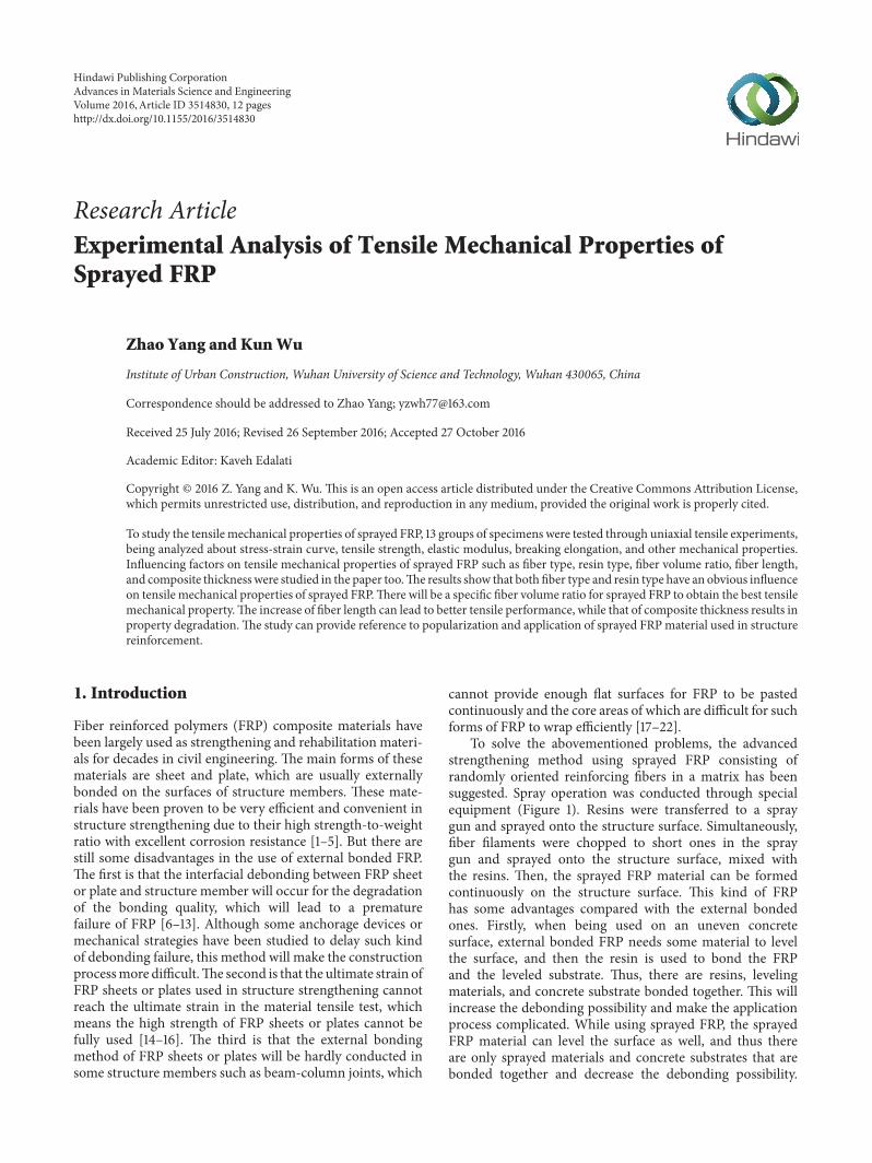
To solve the abovementioned problems, the advancedstrengthening method using sprayed FRP consisting ofrandomly oriented reinforcing fibers in a matrix has beensuggested. Spray operation was conducted through specialequipment (Figure 1). Resins were transferred to a spraygun and sprayed onto the structure surface. Simultaneously,fiber filaments were chopped to short ones in the spraygun and sprayed onto the structure surface, mixed withthe resins. Then, the sprayed FRP material can be formedcontinuously on the structure surface. This kind of FRPhas some advantages compared with the external bondedones. Firstly, when being used on an uneven concretesurface, external bonded FRP needs some material to levelthe surface, and then the resin is used to bond the FRPand the leveled substrate. Thus, there are resins, levelingmaterials, and concrete substrate bonded together. This willincrease the debonding possibility and make the applicationprocess complicated. While using sprayed FRP, the sprayedFRP material can level the surface as well, and thus thereare only sprayed materials and concrete substrates that arebonded together and decrease the debonding possibility.
Hindawi Publishing CorporationAdvances in Materials Science and EngineeringVolume 2016, Article ID 3514830, 12 pageshttp://dx.doi.org/10.1155/2016/3514830
2 Advances in Materials Science and Engineering
Resin pump
Catalyst pump
Resin tank
Spray gun
(a) Complete spray equipment
Chopper unit
Spray nozzle
(b) Spray gun
Figure 1: Special equipment of sprayed FRP.
The application process is simpler as well without a specialleveling process [23]. Secondly, when being used to reinforcea beam-column joint, multilayers of external bonded FRPare required to be bonded on the joint along a differentloading direction, whichmakes the application process muchcomplicated and difficult to assure the construction quality.While using the sprayed FRP, the construction process canbe much easier than external bonded method due to thespraying method.
In 2000, sprayed FRP was used for the first time tostrengthen the reinforced concrete beams by Boyd.The studyshowed that the flexural reinforcing effect of sprayed glassFRP was similar to that of FRP fabric wrap or plate bondingonto the beams, while the shear strengthening effect ofsprayed FRP was better than other techniques [24]. In 2004,Lee and Hausmann investigated the load capacity, ductility,and energy absorption aspect of RC beams retrofitted withsprayed FRP.The study showed that sprayed FRP was capableof substantially increasing the performance of the beams andwas effective in repairing damaged RC beams [25]. Then,Soleimani SM studied sprayed FRP in the shear strength-ening and enhancement of impact resistance of reinforcedconcrete beams [26]. Boyd et al. studied sprayed FRP used inprestressed concrete girders [27]. Ha et al. studied the bondcharacteristics of sprayed FRP composites bonded to concretesubstrate considering various concrete surface conditions[28]. Though the studies above got satisfying results, the useof sprayed FRP for structure strengthening has never beenfully investigated.
This paper is written to study the tensile properties andinfluencing factors of sprayed FRP. A series of specimensof sprayed FRP were tested through tensile experiments.Tensile strength, elastic modulus, breaking elongation, andPoisson ratio of the specimens were studied through the tests.And fiber type, resin type, fiber length, fiber volume ratio,composite thickness, and specimen cutting orientation werecompared as influencing factors in the paper too. The resultscan provide theoretical basis for tensile property calculationand actual application of sprayed FRP.
2. Tensile Tests
2.1. Specimens and Experiment Method. In this paper, 3 typesof fiber, which are glass fiber, carbon fiber, and basalt fiber,and 2 kinds of resin, which are vinyl ester resin (901) andunsaturated polyester resin (196), were used to make sprayedFRP specimens. The fiber yarns and resins used in the studyare shown in Figures 2 and 3. The properties of the fibersand resins are shown in Tables 1 and 2, where the values wereobtained frommaterial suppliers.The special equipment usedto conduct the spraying process is shown in Figure 1.
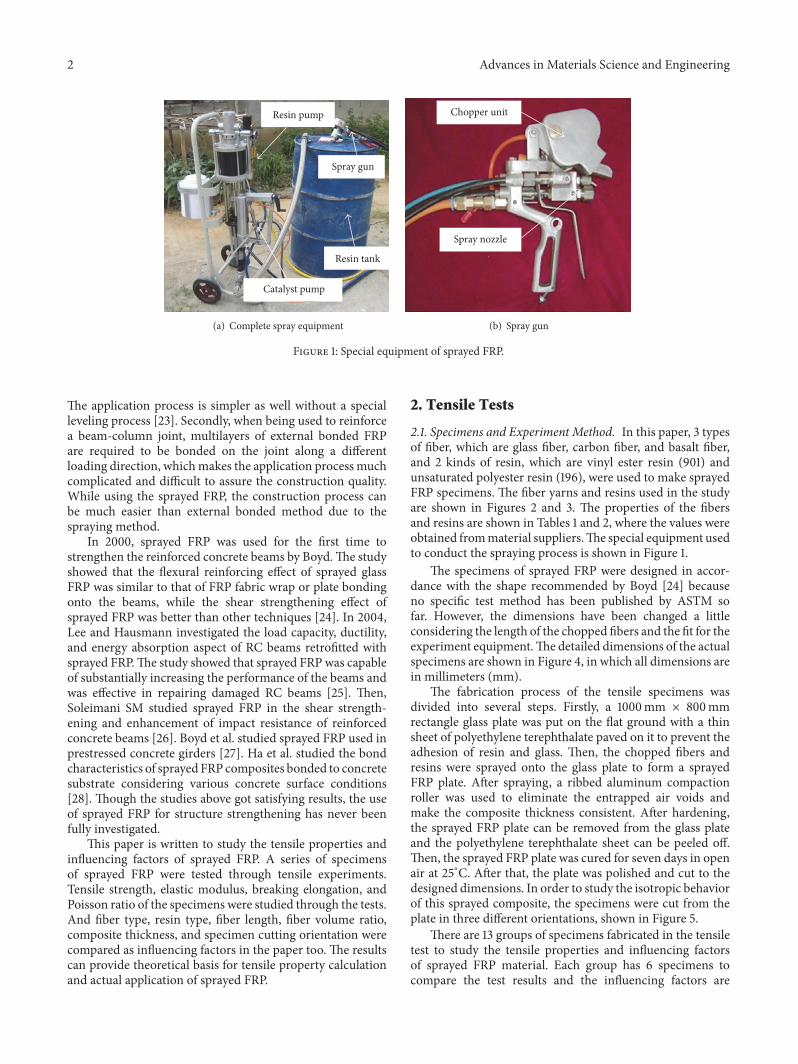
The specimens of sprayed FRP were designed in accor-dance with the shape recommended by Boyd [24] becauseno specific test method has been published by ASTM sofar. However, the dimensions have been changed a littleconsidering the length of the chopped fibers and the fit for theexperiment equipment.The detailed dimensions of the actualspecimens are shown in Figure 4, in which all dimensions arein millimeters (mm).
The fabrication process of the tensile specimens wasdivided into several steps. Firstly, a 1000mm × 800mmrectangle glass plate was put on the flat ground with a thinsheet of polyethylene terephthalate paved on it to prevent theadhesion of resin and glass. Then, the chopped fibers andresins were sprayed onto the glass plate to form a sprayedFRP plate. After spraying, a ribbed aluminum compactionroller was used to eliminate the entrapped air voids andmake the composite thickness consistent. After hardening,the sprayed FRP plate can be removed from the glass plateand the polyethylene terephthalate sheet can be peeled off.Then, the sprayed FRP plate was cured for seven days in openair at 25∘C. After that, the plate was polished and cut to thedesigned dimensions. In order to study the isotropic behaviorof this sprayed composite, the specimens were cut from theplate in three different orientations, shown in Figure 5.
There are 13 groups of specimens fabricated in the tensiletest to study the tensile properties and influencing factorsof sprayed FRP material. Each group has 6 specimens tocompare the test results and the influencing factors are

Advances in Materials Science and Engineering 3
Table 1: Properties of fibers.
Type Tensile strength,𝜎 (MPa)
Elastic modulus,𝐸 (GPa)
Breaking elongation,𝜀 (%)
Poisson ratio,𝜇
Density,𝜌 (kg/m3)
Glass fibera 1970 79 4.8 0.20 2550Carbon fiberb 3500 205 1.5 0.31 1750Basalt fiberc 2200 93 2.6 0.25 2630aData from Jilin Carbon Co., Ltd., in China.bData from Zhejiang GBF Basalt Fiber Co., Ltd., in China.cData from Jushi Group Co., Ltd., in China.
Table 2: Properties of resins.
Type Tensile strength,𝜎 (MPa)
Elastic modulus,𝐸 (GPa)
Breaking elongation,𝜀 (%)
Poisson ratio,𝜇
Density,𝜌 (kg/m3)
901a 85 3.4 5.5 0.3 1050196b 60 3.0 3.0 0.35 1230aData from Swancor Renewable Energy Co., Ltd., in China.bData from Shenzhen Tonglai Material Technology Co., Ltd., in China.
(a) Glass fiber (b) Carbon fiber (c) Basalt fiber
Figure 2: Fiber yarns used in the experiments.
(a) Vinyl ester resin 901 (b) Unsaturated polyester resin 196
Figure 3: Resins used in the experiments.
4 Advances in Materials Science and Engineering
310
R80
80
6050
80 150
8565
(a) Top view
Sprayed FRP
Steel fixture
(b) Front view
Figure 4: Dimensions of the actual specimens.
Sprayed FRP plateSpecimens in 3
cutting orientations 1 2
3 4 5 6
(1000mm × 800mm)
Figure 5: Specimen cutting orientation.
C-1 C-2 B-1 B-2
G-1 G-2 G-3 G-4
G-5 G-6 G-7 G-8
G-9
Figure 6: 13 groups of specimens.
considered as fiber type, resin type, fiber volume ratio, fiberlength, and composite thickness in the paper. The specimenplan is shown in Table 3 and the pictures of the 13 specimengroups are shown in Figure 6.
The composite thickness was controlled by using someplastic plates surrounding the rectangle glass plate on theground, and the required thickness wasmarked on the plasticplates, and then the mark could be used to control thecomposite thickness when spraying. Some concrete blockswere used to fix the plastic plates and prevent deformation.In addition, after cutting the specimens, the thickness of eachspecimen was measured at both sides of the middle section.Themeasurement errors were observed to be below 3% for allspecimens, which indicated that the actual thicknessmet wellthe designed value.
The fiber length can be easily controlled by adjusting thechopped unit. The fiber volume ratio can be well controlledby adjusting the spraying speed of chopped fibers and resins,respectively, as well. It was observed that error percentages
Tensile specimen
Hydraulic pressure universal testingmachine and control system
Strain gauge system
Figure 7: Loading and measurement apparatus.
were both lower than 3%, which could meet the designrequirements well.
The tensile tests were conducted using a hydraulic pres-sure universal testing machine, which is shown in Figure 7.In the middle of every tensile specimen, 2 strain gauges inhorizontal and vertical direction, respectively, were bondedon the specimen surface to measure the strain of the com-posite during loading process through a strain gauge system.The loading speedwas set to be 2mm/min in accordancewithChinese code GB/T1447 (2005) [29].
3. Test Results
3.1. Failure Mode. Through the observation of failure pro-cesses of the specimens, all the 13 groups of specimens aresimilar in failure mode. The failure process can be divided
Advances in Materials Science and Engineering 5
Table 3: Specimen plan.
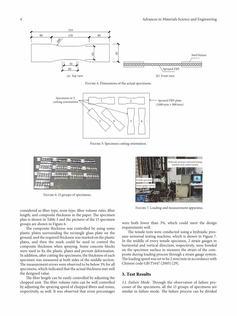
Group number Group name Fiber type Resin type Fiber volume ratio Fiber length (mm) Composite thickness (mm)1 C-1 Carbon 901 20% 30 42 C-2 Carbon 196 20% 30 43 B-1 Basalt 901 20% 30 44 B-2 Basalt 196 20% 30 45 G-1 Glass 901 20% 30 46 G-2 Glass 196 20% 30 47 G-3 Glass 901 15% 30 48 G-4 Glass 901 25% 30 49 G-5 Glass 901 30% 30 410 G-6 Glass 901 20% 15 411 G-7 Glass 901 20% 20 412 G-8 Glass 901 20% 40 413 G-9 Glass 901 20% 30 7
Through crack
(a) Glass fiber
Through crack
(b) Basalt fiber
Through crack
(c) Carbon fiber
Figure 8: Through cracks in sprayed FRP specimens of different fiber types.
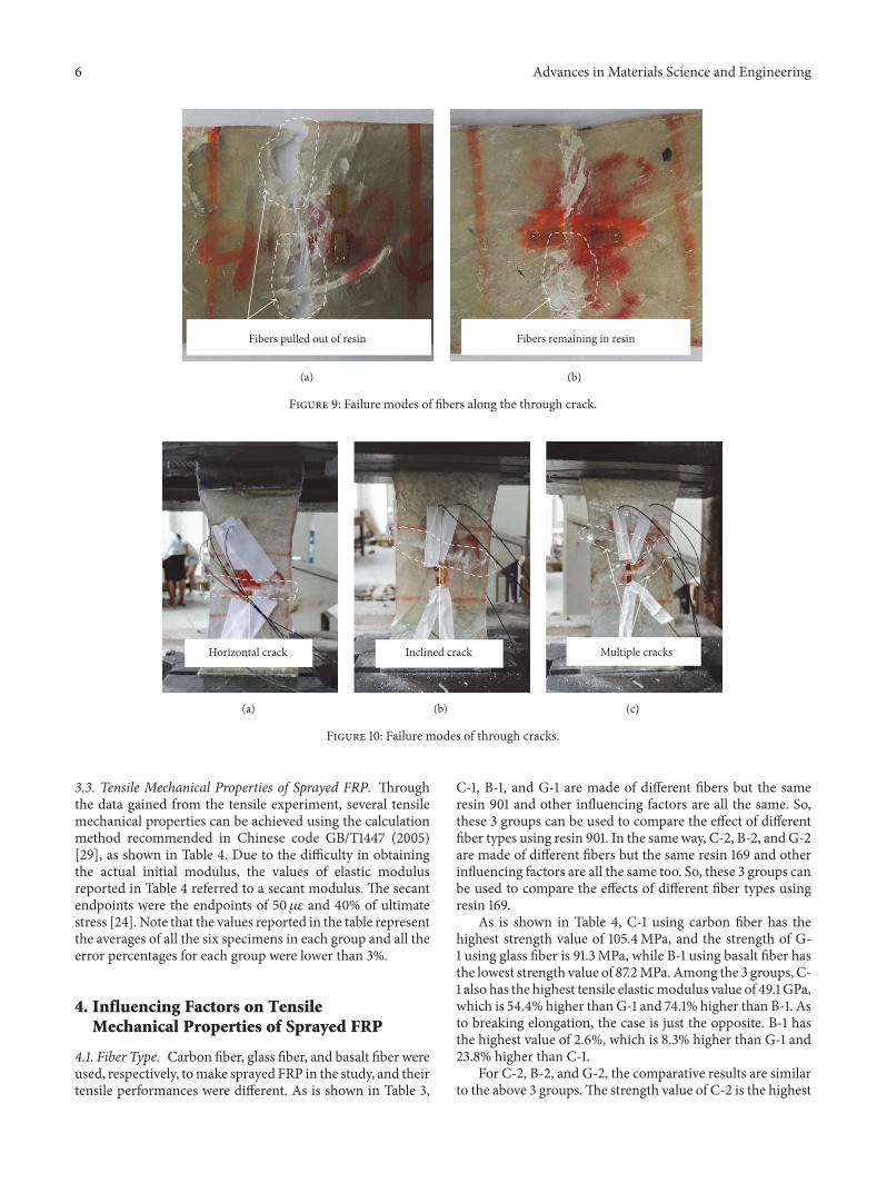
into 3 stages. In the first stage, the stress in the compositeincreased quickly with the increase of tensile load, whilestrain increased slowly. It was observed that there are nosigns of cracking or debonding inside the specimens, whichalways appeared like some small white lines. In the secondstage, initial crack could be observed.The strain in compositeincreased fast, while stress increased slowly. Cracks usuallystarted at the edge of the composite and progressed rapidly tothe center. Fracture always began in resin and then debondingoccurred between fiber and resin, which made the fiberpull out of the resin and led to crack development. In thethird stage, the specimen reached the ultimate load. Thestress began to decrease rapidly and strain increased a little.Through cracks were formed (Figure 8) and resulted in atotal failure of the specimens. Some fibers along the throughcracks were pulled out and some still remained in the resin(Figure 9). There were 3 main modes for the through cracks,which are shown in Figure 10.
3.2. Stress-Strain Relationship. The tensile stress of sprayedFRP can be calculated by dividing the load value by the
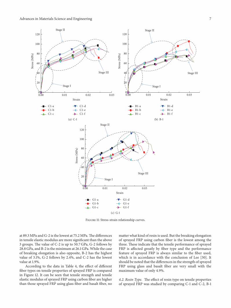
cross-sectional area of the specimen. The strain of sprayedFRP can be collected automatically by the strain gaugesystem. Thus, the experimental stress-strain relationship canbe achieved. The relationship curves of the 13 groups arevery similar and 3 groups of them are shown as examplesin Figure 11, from which we can see the 3 stages of thefailure process clearly. From Figure 11, we can see that, inthe first stage, fibers and resins were working together tobear the tensile load, no cracking or debonding appeared,the strain increased slower than stress, and the first stageof the curve was formed. While the initial cracks appeared,some resins ruptured and debonding between fibers andresins appeared. The deformation of specimens increasedmore quickly than the loads, and thus the second stage ofthe curve was formed. When the cracks developed, moreand more resins ruptured, the loads were mainly borne byfibers until reaching the bearing capacity, and the ultimatestress of specimens was reached. Then, the stress started todecrease and strain continued to increase. The third stageof the curve was formed. So, the sprayed FRP compositesshowed a trilinear constitutive behavior.
6 Advances in Materials Science and Engineering
Fibers pulled out of resin
(a)
Fibers remaining in resin
(b)
Figure 9: Failure modes of fibers along the through crack.
Horizontal crack
(a)
Inclined crack
(b)
Multiple cracks
(c)
Figure 10: Failure modes of through cracks.
3.3. Tensile Mechanical Properties of Sprayed FRP. Throughthe data gained from the tensile experiment, several tensilemechanical properties can be achieved using the calculationmethod recommended in Chinese code GB/T1447 (2005)[29], as shown in Table 4. Due to the difficulty in obtainingthe actual initial modulus, the values of elastic modulusreported in Table 4 referred to a secant modulus. The secantendpoints were the endpoints of 50 𝜇𝜀 and 40% of ultimatestress [24]. Note that the values reported in the table representthe averages of all the six specimens in each group and all theerror percentages for each group were lower than 3%.
4. Influencing Factors on TensileMechanical Properties of Sprayed FRP
4.1. Fiber Type. Carbon fiber, glass fiber, and basalt fiber wereused, respectively, tomake sprayed FRP in the study, and theirtensile performances were different. As is shown in Table 3,
C-1, B-1, and G-1 are made of different fibers but the sameresin 901 and other influencing factors are all the same. So,these 3 groups can be used to compare the effect of differentfiber types using resin 901. In the same way, C-2, B-2, and G-2are made of different fibers but the same resin 169 and otherinfluencing factors are all the same too. So, these 3 groups canbe used to compare the effects of different fiber types usingresin 169.
As is shown in Table 4, C-1 using carbon fiber has thehighest strength value of 105.4MPa, and the strength of G-1 using glass fiber is 91.3MPa, while B-1 using basalt fiber hasthe lowest strength value of 87.2MPa. Among the 3 groups, C-1 also has the highest tensile elasticmodulus value of 49.1 GPa,which is 54.4% higher than G-1 and 74.1% higher than B-1. Asto breaking elongation, the case is just the opposite. B-1 hasthe highest value of 2.6%, which is 8.3% higher than G-1 and23.8% higher than C-1.
For C-2, B-2, and G-2, the comparative results are similarto the above 3 groups.The strength value of C-2 is the highest
Advances in Materials Science and Engineering 7
0
20
40
60
80
100
120
Stage I
Stage II
Stage III
Stre
ss (M
Pa)
0.00 0.01 0.02 0.03Strain
C1-aC1-bC1-c
C1-dC1-eC1-f
(a) C-1
Stage I
Stage II
Stage III
0
20
40
60
80
100
120
Stre
ss (M
Pa)
0.00 0.01 0.02 0.03Strain
B1-aB1-bB1-c
B1-dB1-eB1-f
(b) B-1
0
20
40
60
80
100
120
Stage I
Stage II
Stage III
Stre
ss (M
Pa)
0.00 0.01 0.02 0.03Strain
G1-aG1-bG1-c
G1-dG1-eG1-f
(c) G-1
Figure 11: Stress-strain relationship curves.
at 89.3MPa and G-2 is the lowest at 75.2MPa.The differencesin tensile elastic modulus are more significant than the above3 groups. The value of C-2 is up to 50.7GPa, G-2 follows by28.8GPa, and B-2 is theminimum at 26.1 GPa.While the caseof breaking elongation is also opposite, B-2 has the highestvalue of 3.1%, G-2 follows by 2.4%, and C-2 has the lowestvalue at 1.9%.
According to the data in Table 4, the effect of differentfiber types on tensile properties of sprayed FRP is comparedin Figure 12. It can be seen that tensile strength and tensileelastic modulus of sprayed FRP using carbon fiber are higherthan those sprayed FRP using glass fiber and basalt fiber, no
matter what kind of resin is used. But the breaking elongationof sprayed FRP using carbon fiber is the lowest among thethree. These indicate that the tensile performance of sprayedFRP is affected greatly by fiber type and the performancefeature of sprayed FRP is always similar to the fiber used,which is in accordance with the conclusion of Lee [30]. Itshould be noted that the differences in the strength of sprayedFRP using glass and basalt fiber are very small with themaximum value of only 4.9%.
4.2. Resin Type. The effect of resin type on tensile propertiesof sprayed FRP was studied by comparing C-1 and C-2, B-1

8 Advances in Materials Science and Engineering
Tens
ile st
reng
th (M
Pa)
120
100
80
60
40
20
0
Carbon BasaltFiber type
Glass
Sprayed FRP using resin 901
Sprayed FRP using resin 196
(a) Tensile strengthEl
astic
mod
ulus
(GPa
)
60
50
40
30
20
10
0
Sprayed FRP using resin 901
Sprayed FRP using resin 196
Carbon BasaltFiber type
Glass
(b) Elastic modulus
Brea
king
elon
gatio
n
3.5
3
2.5
2
1.5
1
0.5
0
Sprayed FRP using resin 901
Sprayed FRP using resin 196
Carbon BasaltFiber type
Glass
(c) Breaking elongation
Figure 12: Comparison of tensile properties of sprayed FRP using different fiber types.
and B-2, and G-1 and G-2, separately, which are different inresin type but the same in all other factors. C-1, B-1, and G-1 used vinyl ester resins. C-2, B-2, and G-2 used unsaturatedpolyester resins. As is shown in Table 4, tensile strength ofC-1 is 18.2% higher than C-2, B-1 is 6.3% higher than B-2,and G-1 is 21.4% higher than G-2. Regarding tensile elasticmodulus, the values of C-1, G-1, and B-1 are also higher thanthose of C-2, B-2, andG-2. But, in the comparison of breakingelongation, the cases are different. The value of C-1 is 10.5%higher than C-2, the value of B-1 is 8.3% higher than B-2, andthe value of G-1 is 20% lower than G-2.
The above results show that using vinyl ester resin asmatrix and adhesive for sprayed FRP can get better tensilemechanical properties generally, which is similar to the resultof Lee [30]. But it is worth noting that the breaking elongationof the sprayed FRP using glass fiber will be reduced whenusing this kind of resin.
4.3. Fiber Volume Ratio. From Table 3, there are 4 groups ofspecimens used to study the effect of fiber volume ratio ontensile properties of sprayed FRP, which are G-3, G-1, G-4,
Advances in Materials Science and Engineering 9
Tens
ile st
reng
th (M
Pa)
100
80
60
40
20
0
Fiber volume ratio (%)15 20 25 30
(a) Tensile strengthEl
astic
mod
ulus
(GPa
)
40
20
0
Fiber volume ratio (%)15 20 25 30
(b) Elastic modulus
Brea
king
elon
gatio
n
3
2
1
0
Fiber volume ratio (%)15 20 25 30
(c) Breaking elongation
Figure 13: Comparison of tensile properties of sprayed FRP in different fiber volume ratios.
andG-5, with a fiber volume ratio of 15%, 20%, 25%, and 30%,respectively.
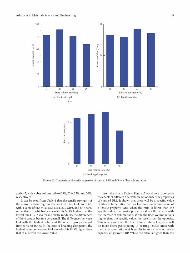
It can be seen from Table 4 that the tensile strengths ofthe 4 groups from high to low are G-1, G-3, G-4, and G-5,with a value of 91.3MPa, 82.6MPa, 80.3MPa, and 67.7MPa,respectively.The highest value of G-1 is 34.9% higher than thelowest one G-5. As to tensile elastic modulus, the differencesof the 4 groups became very small. The differences betweenG-4 with the highest value and the other 3 groups rangedfrom 6.7% to 15.4%. In the case of breaking elongation, thehighest value comes fromG-4 too, which is 56.3%higher thanthat of G-5 with the lowest value.
From the data in Table 4, Figure 13 was drawn to comparethe effects of different fiber volume ratios on tensile propertiesof sprayed FRP. It shows that there will be a specific valueof fiber volume ratio that can lead to a maximum value ofa tensile property. And when the ratio is lower than thespecific value, the tensile property value will increase withthe increase of volume ratio. While the fiber volume ratio ishigher than the specific value, the case is just the opposite.This is because when the fiber volume ratio is low, there willbe more fibers participating in bearing tensile stress withthe increase of ratio, which results in an increase of tensilecapacity of sprayed FRP. While the ratio is higher than the

10 Advances in Materials Science and Engineering
Table 4: Summary of tensile properties of sprayed FRP.
Group number Groupname
Tensile strength, 𝜎(MPa)
Elastic modulus, E(GPa)
Breaking elongation(%) Poisson ratio, 𝜇
1 C-1 105.4 49.1 2.1 0.302 C-2 89.3 50.7 2.3 0.313 B-1 87.2 28.2 2.6 0.224 B-2 78.9 26.1 3.0 0.255 G-1 91.3 31.8 2.4 0.246 G-2 75.2 28.8 3.0 0.267 G-3 82.6 33.3 2.2 0.228 G-4 80.3 36.7 2.5 0.259 G-5 67.7 34.4 1.6 0.2410 G-6 78.1 27.1 2.1 0.2111 G-7 87.1 30.8 2.2 0.2612 G-8 101.2 38.3 2.4 0.2413 G-9 66.1 23.7 1.9 0.24
specific value, fibers will be too much, and thus the resinaround the fibers will not be enough to transfer and balancethe stress of fibers effectively, which will lead to partial failurein some fibers or resins earlier and make the tensile propertyreduced.
4.4. Fiber Length. From Table 3, there are 4 groups ofspecimens used to study the effect of fiber length on tensileproperties of sprayed FRP, which are G-6, G-7, G-1, and G-8, with a fiber length of 15mm, 20mm, 30mm, and 40mm,respectively.
From Table 4, tensile strengths of the 4 groups from highto low are G-8, G-1, G-7, and G-6, with a value of 101.2MPa,91.3MPa, 87.1MPa, and 78.1MPa, respectively. For tensileelastic modulus, the highest value also belongs to G-8, whichis 41.3% higher than the lowest one G-6. As to breakingelongation, the highest value is 2.4% which comes from G-8 and G-1, followed by 2.2% from G-7, and the lowest one is2.1% from G-6.
The relationship curves of tensile stress and strain of the4 groups are compared in Figure 14. It shows that the longerfiber can bear more stress than the shorter ones when tensilestrain is the same, which is in accordance with Boyd’s result[24]. This can be explained as the longer length fibers canobtain a larger bonding areawith resins, and thus the bondingeffect will be better than the shorter ones, which can lead tobetter tensile properties.
4.5. Composite Thickness. From Table 3, there are 2 groups ofspecimens used to study the effect of composite thickness ontensile properties of sprayed FRP, which are G-1 with a 4mmthickness and G-9 with a 7mm thickness.
From Table 4, the tensile strength of G-1 is 91.3MPa andthat of G-9 is 66.1MPa. The tensile elastic modulus of G-1 is 31.8 GPa and that of G-9 is 23.7 GPa. As to breakingelongation,G-1 is 2.4% andG-9 is 1.9%. It is shown that tensilestrength, elastic modulus, and breaking elongation will all
Strain0.00 0.01 0.02 0.03
0
20
40
60
80
100St
ress
(MPa
)
G-6 (15mm)G-7 (20mm)
G-1 (30mm)G-8 (40mm)
Figure 14: Comparison of stress-strain curves of sprayed FRP withdifferent fiber lengths.
be reduced with the increase of composite thickness. Thisis because the initial defects in sprayed FRP materials willbecomemorewith the increase of composite thickness, whichwill lead to degradation of tensile properties.
4.6. Specimen Cutting Orientation. All the specimens werecut from the sprayed FRP plate in three different orientations,which is shown in Figure 5. Asmentioned before, all the errorpercentages for each group in Table 4 were lower than 3%, sothere was not any obvious difference in tensile properties ofthe specimens in different cutting orientations in each group.Comparing the Poisson ratios of the 13 groups of specimens inTable 4, most values are close to the average value of 0.25.Theabove results indicate that the sprayed FRP composite can beseen as an isotropic material.
Advances in Materials Science and Engineering 11
5. Summary and Conclusions
This paper has studied the tensile properties of sprayed FRPthrough tensile experiments of 13 groups of specimens, whichinclude tensile strength, elastic modulus, breaking elonga-tion, and Poisson ratio. The effects of several influencingfactors are compared too. The following conclusions aredrawn:
(1) Fiber type has an important influence on tensileproperties of sprayed FRP material. The compositesmade of carbon fiber have higher values of tensilestrength and elastic modulus than thosemade of glassfiber or basalt fiber, while the breaking elongation ofcarbon fiber composites is lower. The results equatethe tensile properties of the three types of fibers.
(2) The test results of the 2 resins used in this paper showthat using vinyl ester resins to make sprayed FRP canget better tensile properties than using unsaturatedpolyester resins generally. But the breaking elongationof glass fiber specimens using vinyl ester resins islower compared with using unsaturated polyesterresin.
(3) There will be a specific value of fiber volume ratio forevery kind of sprayed FRP material, which can leadto the highest value of a tensile property. Less or morethan this volume ratio can make the tensile propertyof this sprayed FRP degrade.
(4) The increase of fiber length can make the tensileproperties of sprayed FRP better, while the increaseof composite thickness will lead to property degrada-tion.
(5) Cutting orientation of sprayed FRP specimens has noobvious influence on tensile properties and the Pois-son ratios are almost the same for all the specimens,which shows that sprayed FRP can be looked at as akind of isotropic material.
Competing Interests
The authors declare that there are no competing interestsregarding the publication of this paper.
Acknowledgments
This research received specific grant from the ResearchFoundation of Wuhan Construction Committee and wassupported by China Scholarship Council as well.
References
[1] W. Li, “The study and application of FRP material in concretestructures,” Research of Materials Science, vol. 3, no. 1, pp. 17–21,2014.
[2] H. Karpate, H. Wheat, J. Jirsa, D. Fowler, and D. Whitney,“Repair and rehabilitation of corrosiondamaged concrete ele-ments using FRP composite wraps,”World Journal of Engineer-ing, vol. 8, no. 2, pp. 147–150, 2011.
[3] G. Portnov, C. E. Bakis, E. Lackey, and V. Kulakov, “FRP Rein-forcing bars—designs and methods of manufacture (Review ofPatents),” Mechanics of Composite Materials, vol. 49, no. 4, pp.381–400, 2013.
[4] A. Prota, G. Manfredi, and F. P. Nardone, “Assessment of designformulas for in-plane FRP strengthening of masonry walls,”Journal of Composites for Construction, vol. 12, no. 6, pp. 643–649, 2008.
[5] S. S. Pendhari, T. Kant, and Y.M. Desai, “Application of polymercomposites in civil construction: a general review,” CompositeStructures, vol. 84, no. 2, pp. 114–124, 2008.
[6] J. G. Teng, H. Yuan, and J. F. Chen, “FRP-to-concrete interfacesbetween two adjacent cracks: theoretical model for debondingfailure,” International Journal of Solids and Structures, vol. 43,no. 18-19, pp. 5750–5778, 2006.
[7] B. Ferracuti, M. Savoia, and C.Mazzotti, “Interface law for FRP-concrete delamination,” Composite Structures, vol. 80, no. 4, pp.523–531, 2007.
[8] C. Mazzotti and M. Savoia, “FRP-Concrete bond behaviourunder cyclic debonding force,” Advances in Structural Engineer-ing, vol. 12, no. 6, pp. 771–780, 2009.
[9] H. C. Biscaia, I. S. Borba, C. Silva, and C. Chastre, “A nonlinearanalytical model to predict the full-range debonding processof FRP-to-parent material interfaces free of any mechanicalanchorage devices,” Composite Structures, vol. 138, pp. 52–63,2016.
[10] H. W. Zhang, S. T. Smith, and R. J. Gravina, “Analysis ofFRP-to-concrete interfaces using a displacement driven partialinteractionmodel,” International Journal ofMechanical Sciences,vol. 117, pp. 210–217, 2016.
[11] T. Xu, Z. J. He, C. A. Tang, W. C. Zhu, and P. G. Ranjith,“Finite element analysis of width effect in interface debondingof FRP plate bonded to concrete,” Finite Elements in Analysisand Design, vol. 93, pp. 30–41, 2015.
[12] M. Coelho, A. Caggiano, J. Sena-Cruz, and L. Neves, “Fracture-based interface model for NSM FRP systems in concrete,”Composite Structures, vol. 152, pp. 816–828, 2016.
[13] H. C. Biscaia, D. Cruz, and C. Chastre, “Analysis of thedebonding process of CFRP-to-timber interfaces,”Constructionand Building Materials, vol. 113, pp. 96–112, 2016.
[14] S. F. Brena and G. N. McGuirk, “Advances on the behaviorcharacterization of FRP-Anchored Carbon Fiber-ReinforcedPolymer (CFRP) sheets used to strengthen concrete elements,”International Journal of Concrete Structures and Materials, vol.7, no. 1, pp. 3–16, 2013.
[15] S. C. Chin, N. Shafiq, and M. F. Nuruddin, “FRP as strengthen-ing material for Reinforced Concrete beams with openings—areview,”KSCE Journal of Civil Engineering, vol. 19, no. 1, pp. 213–219, 2014.
[16] W.-W. Wang, J.-G. Dai, and K. A. Harries, “Performanceevaluation of RCbeams strengthenedwith an externally bondedFRP system under simulated vehicle loads,” Journal of BridgeEngineering, vol. 18, no. 1, pp. 76–82, 2013.
[17] S. S. Mahini and H. R. Ronagh, “Strength and ductility of FRPweb-bonded RC beams for the assessment of retrofitted beam-column joints,” Composite Structures, vol. 92, no. 6, pp. 1325–1332, 2010.
[18] K. Amin, “Investigation on the effects of L-shaped FRPs forstrengthening of exterior RC joints to relocate the plastic hingeplace away from the column face,” International Journal ofAdvances in Engineering Sciences, vol. 3, no. 2, pp. 13–18, 2013.
12 Advances in Materials Science and Engineering
[19] Z. Yang and C. Wu, “Analysis on the seismic performance ofRC frame beam-column joints strengthened by sprayed FRP,”Applied Mechanics and Materials, vol. 578-579, pp. 835–838,2014.
[20] P.Agarwal, A.Gupta, andR.G.Angadi, “Effect of FRPwrappingon axial behavior of concrete and cyclic behavior of external RCbeam column joints,” KSCE Journal of Civil Engineering, vol. 18,no. 2, pp. 566–573, 2014.
[21] A. Bossio, F. Fabbrocino, G. P. Lignola, A. Prota, and G.Manfredi, “Simplified model for strengthening design of beam-column internal joints in reinforced concrete frames,” Polymers,vol. 7, no. 9, pp. 1732–1754, 2015.
[22] E. Z. Beydokhty and H. Shariatmadar, “Behavior of damagedexterior RC beam-column joints strengthened by CFRP com-posites,” Latin American Journal of Solids and Structures, vol. 13,no. 5, pp. 880–896, 2016.
[23] H. K. Lee, “Effectiveness of anchorage in concrete beamsretrofitted with sprayed fiber-reinforced polymers,” Journal ofReinforced Plastics andComposites, vol. 23, no. 12, pp. 1285–1300,2004.
[24] A. J. Boyd, Rehabilitation of reinforced concrete beams withsprayed glass giber reinforced polymers [Ph.D. thesis], Universityof British Columbia, British Columbia, Canada, 2000.
[25] H. K. Lee and L. R. Hausmann, “Structural repair and strength-ening of damaged RC beams with sprayed FRP,” CompositeStructures, vol. 63, no. 2, pp. 201–209, 2004.
[26] S. M. Soleimani, Sprayed glass fibre reinforced polymers in shearstrengthening and enhancement of impact resistance of reinforcedconcrete beams [Ph.D. thesis], University of British Columbia,Vancouver, Canada, 2006.
[27] A. J. Boyd, N. F. Liang, P. S. Green, and K. Lammert, “SprayedFRP repair of simulated impact in prestressed concrete girders,”Construction and Building Materials, vol. 22, no. 3, pp. 411–416,2008.
[28] S. K. Ha, S. Na, and H. K. Lee, “Bond characteristics of sprayedFRP composites bonded to concrete substrate consideringvarious concrete surface conditions,” Composite Structures, vol.100, pp. 270–279, 2013.
[29] GB/T 1447, Fiber-Reinforced Plastics Composites- Determinationof Tensile Properties, 2005.
[30] K. S. Lee, “A seismic strengthening technique for reinforcedconcrete columns using Sprayed FRP,” Journal of AdvancedConcrete Technology, vol. 10, pp. 219–230, 2012.

Submit your manuscripts athttp://www.hindawi.com
ScientificaHindawi Publishing Corporationhttp://www.hindawi.com Volume 2014
CorrosionInternational Journal of
Hindawi Publishing Corporationhttp://www.hindawi.com Volume 2014
Polymer ScienceInternational Journal of
Hindawi Publishing Corporationhttp://www.hindawi.com Volume 2014
Hindawi Publishing Corporationhttp://www.hindawi.com Volume 2014
CeramicsJournal of
Hindawi Publishing Corporationhttp://www.hindawi.com Volume 2014
CompositesJournal of
NanoparticlesJournal of
Hindawi Publishing Corporationhttp://www.hindawi.com Volume 2014
Hindawi Publishing Corporationhttp://www.hindawi.com Volume 2014
International Journal of
Biomaterials
Hindawi Publishing Corporationhttp://www.hindawi.com Volume 2014
NanoscienceJournal of
TextilesHindawi Publishing Corporation http://www.hindawi.com Volume 2014
Journal of
NanotechnologyHindawi Publishing Corporationhttp://www.hindawi.com Volume 2014
Journal of
CrystallographyJournal of
Hindawi Publishing Corporationhttp://www.hindawi.com Volume 2014
The Scientific World JournalHindawi Publishing Corporation http://www.hindawi.com Volume 2014
Hindawi Publishing Corporationhttp://www.hindawi.com Volume 2014
CoatingsJournal of
Advances in
Materials Science and EngineeringHindawi Publishing Corporationhttp://www.hindawi.com Volume 2014
Smart Materials Research
Hindawi Publishing Corporationhttp://www.hindawi.com Volume 2014
Hindawi Publishing Corporationhttp://www.hindawi.com Volume 2014
MetallurgyJournal of
Hindawi Publishing Corporationhttp://www.hindawi.com Volume 2014
BioMed Research International
MaterialsJournal of
Hindawi Publishing Corporationhttp://www.hindawi.com Volume 2014
Nano
materials
Hindawi Publishing Corporationhttp://www.hindawi.com Volume 2014
Journal ofNanomaterials
![Research Article Brittle Creep Failure, Critical Behavior ...downloads.hindawi.com/journals/amse/2015/101035.pdf · ] on creep failure of concrete focus mainly on tensile and exural](https://static.fdocuments.us/doc/165x107/5f452273e03bcb5bf076190b/research-article-brittle-creep-failure-critical-behavior-on-creep-failure.jpg)