REPORTDOCUMENT PGE OMB No. 0704-0 8
104
CForm Approved REPORTDOCUMENT _ __ _PGE OMB No. 0704-0 8 -i rd trt~r~r~ ? ' ta n O.Me. 'Ins C ' ng, itv na 'vo-rq t?-e ntV ot -1: -ao na : em -'a .t ts b ,.j ~r'aeV t o~ ~ 'n, 1-4tior, o 1 O -c: c o irt -,,,qto ouce ]C urir s '-~~.- - - ' , ci5 oiirs.ia - :is . . ., t n 12C4 .. ' -ltOn . '. V1d."2 i-a t jf,.e )t M,,Cne-eit tr C nc oer-c, '_, ' 324nt ", . 1. AGENCY USE ONLY ,heave olank) j2. REPORT DATE j 3. REPORT TYPE AND DATES COVERED I Mkrrh 1QQlI Paper Jan 89 - Sep 89 14. DTLE AND SUBTITLE 5. '"NDIN-G NUMBERS 0 Thin-Layer Navier-Stokes Solutions of the Asymmetric ! PE: 61102F Vnrtirul Flnw nn A Tmnnan+ fniva RndW PR: 2307 AUTHOR(S) TA: El WU: 26 O AFATL Program Manager: Kirk J. Vanden PERFORMING ORGANIZATION NAME(S) AND ADDRESS(ES) 8. PERFORMING ORGANIZATION NREPORT NUMBER ~ Aerodynamics Branch Aeromechanics Division Air Force Armament Laboratory (AFATL/FXA) AFATL-TP-90-04 O--I Eqlin Air Force Base, FL 32542-5434 _ SPONSORING/MONITORING AGENCY NAME(S) AND ADDRESS(ES) 10. SPONS iI AGENCY!ER'N R ":',-. ,,= 21990 I'. fUPPLEMENTARY NOTES 2..i,..;o; This paper was not edited nor published by AFATL/D01R. 12-. UISTRIBUTION'AVAILABILITY STATEMENT 12b. DISTRIBUTION CODE Approved for public release; distribution is unlimited ! '. ,.35TRACT f.klax~rrn urn 200 wordls) q -- " 2 Laminar solutions for asymmetric vortical flow on a five caliber tangent ogive with an eight caliber cylindrical afterbody were calculated with a thin-layer Navier- Stokes code on a one block algebraic grid. Solutions were obtained for Mach 1.4 at 25, 30, 37.5, 38.5, and 40_degeesanglet of attack. The Reynolds number for all cases was 200,000 based on lthV maximum body diameter. Two-dimensional particle traces in cross-sections of the flow and the limiting streamlines were calculated from the solutions. (The validity of the thin-layer approximation in the flow field far away from the boundary layer was studied by recomputing the 37.5 degt'ee case with the viscosity turned off at a distance away from the body. The solution was not significantly different, indicating that the outer vortex flow is basically inviscid.- Both symmetric and asymmetric cases were calculated and analyzed. "The secondary flow was shown in detail. "The complexity of the, secondary flow increased with angle of attack. 2, Crossflow topology diagrams were given in detail for symmetric and asymmetric conditions to illustrate the fundamental difference between L OBJECT TERMS "5 NUMBER (2F PAGES I 16. PRICE CODE SECURITY CLASSIFICATION 18. SECURITY CLASSIFICATION 19 SECURITY CLASSIFICATION 20. LIMITATION OFABSTRACT )F 1E PORT C AOF THIS PAGE OF ABSTRAC2 Hli -CIATFTFDJ I II AqfTPTFfn I lINCI ASCTFTFFn gad •0 0,,2 107 9 0 0 4 1 ,'....., '.... .. . .
Transcript of REPORTDOCUMENT PGE OMB No. 0704-0 8
CForm Approved
REPORTDOCUMENT _ __ _PGE OMB No. 0704-0 8
-i rd trt~r~r~ ? ' ta n O.Me. 'Ins C ' ng, itv na 'vo-rq t?-e ntV ot -1: -ao na : em -'a .t ts b ,.j ~r'aeV t o~ ~'n, 1-4tior, o 1 O -c: c o irt -,,,qto ouce ]C urir s '-~~.- - - ' , ci5 oiirs.ia - :is
. . ., t n 12C4 .. ' -ltOn . '. V1d."2 i-a t jf,.e )t M,,Cne-eit tr C nc oer-c, '_, ' 324nt ", .
1. AGENCY USE ONLY ,heave olank) j2. REPORT DATE j 3. REPORT TYPE AND DATES COVERED
I Mkrrh 1QQlI Paper Jan 89 - Sep 8914. DTLE AND SUBTITLE 5. '"NDIN-G NUMBERS
0 Thin-Layer Navier-Stokes Solutions of the Asymmetric ! PE: 61102FVnrtirul Flnw nn A Tmnnan+ fniva RndW PR: 2307AUTHOR(S) TA: El
WU: 26
O AFATL Program Manager: Kirk J. VandenPERFORMING ORGANIZATION NAME(S) AND ADDRESS(ES) 8. PERFORMING ORGANIZATION
NREPORT NUMBER
~ Aerodynamics BranchAeromechanics DivisionAir Force Armament Laboratory (AFATL/FXA) AFATL-TP-90-04
O--I Eqlin Air Force Base, FL 32542-5434 _
SPONSORING/MONITORING AGENCY NAME(S) AND ADDRESS(ES) 10. SPONS iIAGENCY!ER'N R
":',-. ,,= 21990
I'. fUPPLEMENTARY NOTES 2..i,..;o;
This paper was not edited nor published by AFATL/D01R.
12-. UISTRIBUTION'AVAILABILITY STATEMENT 12b. DISTRIBUTION CODE
Approved for public release; distribution is unlimited! '. ,.35TRACT f.klax~rrn urn 200 wordls) q
-- "2 Laminar solutions for asymmetric vortical flow on a five caliber tangent ogive
with an eight caliber cylindrical afterbody were calculated with a thin-layer Navier-Stokes code on a one block algebraic grid.
Solutions were obtained for Mach 1.4 at 25, 30, 37.5, 38.5, and 40_degeesangletof attack. The Reynolds number for all cases was 200,000 based on lthV maximum bodydiameter. Two-dimensional particle traces in cross-sections of the flow and thelimiting streamlines were calculated from the solutions.
(The validity of the thin-layer approximation in the flow field far away from theboundary layer was studied by recomputing the 37.5 degt'ee case with the viscosityturned off at a distance away from the body. The solution was not significantly
different, indicating that the outer vortex flow is basically inviscid.-Both symmetric and asymmetric cases were calculated and analyzed. "The secondary
flow was shown in detail. "The complexity of the, secondary flow increased with angleof attack. 2,
Crossflow topology diagrams were given in detail for symmetric andasymmetric conditions to illustrate the fundamental difference between
L OBJECT TERMS "5 NUMBER (2F PAGES I
16. PRICE CODE
SECURITY CLASSIFICATION 18. SECURITY CLASSIFICATION 19 SECURITY CLASSIFICATION 20. LIMITATION OFABSTRACT
)F 1E PORT C AOF THIS PAGE OF ABSTRAC2
Hli -CIATFTFDJ I II AqfTPTFfn I lINCI ASCTFTFFn gad
•0 0,,2 1079 0 0 4 1 ,'....., '.... .. . .
V
13. ABSTRACT (CONCLUDED)
thes'e conditions. Asymmetry,..according to this research,, wascharacterized by the change in-the topological structure nearthe saddle point associated with the primary vortices. In ad-dition, the--reation of vortex-by &the, pinching of another vor-tex ,was found to occur. This phenomenon was observed in both
-the primary and secondary flow. K IThe singular points obtained from the two-dimensional par-
ticle traces satisfied the topological summation rule for two-dimensional sections of a three-dimensional flow. The primaryseparation and associated vortices agree qualitatively with ex-perimental data. The secondary separation region, however,contained additional topological structures that have not beenresolved in previous experimental studies.
PREFACE
This paper was prepared by Kirk J. Vanden of the ComputationalFluid Dynamics Section, Aerodynamics Branch, Aeromechanics Divi-sion, Air Force Armament Laboratory, Eglin Air Force Base, Flo-rida. The work was performed under Work Unit 2307E126 during theperiod from January 1989 to September 1989.
This paper presents an investigation of asymetric vorticalflow on a tangent ogive body based upon solutions obtained by athin-layer Navier-Stokes code in use in the Computational FluidDynamics Section.
NTiS '',
J 2' ,
A I
iii/iv (Blank)
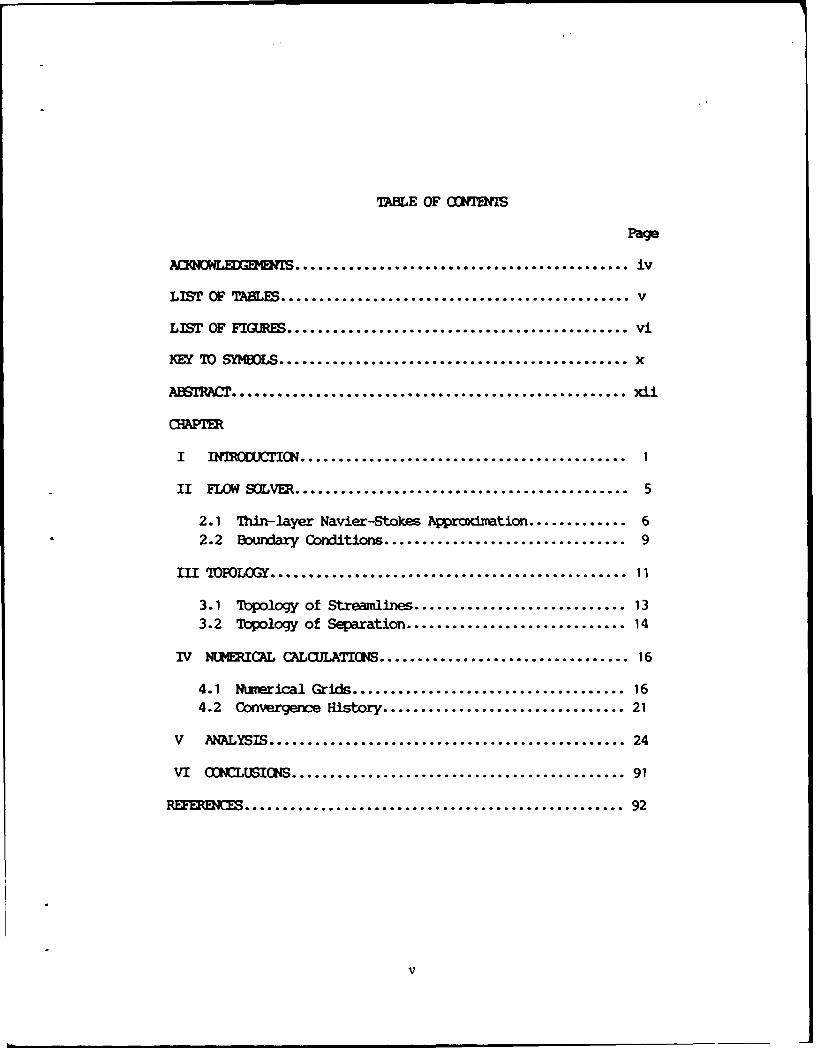
TA1BLE OF Cfmf1S
Page
AOWLED1M. ........................................ iv
LIST OF %BLES ............................................ v
LIST OF FIGRES .......................................... vi
KEY 70 SYMBOLS........................................... x
A1A= .................................................. xii
I 1C N ........................................... 1
II FLOW SOLVER ............................................ 5
2.1 Thin-layer Navier-Stokes Approximation ............. 62.2 Boundary Conditions ................................ 9
III FOLOGY ............................................ 11
3.1 Topology of Streamlines ............................ 133.2 Tiopology of Separation ............................. 14
IV NUMERICAL CALOJIATINS ................................. 16
4.1 Numerical Grids .................................. 164.2 Convergence History .............................. 21
V ANALYSIS ............................................... 24
VI (ONCLUSICNS ............................................ 91
.............................................. 92
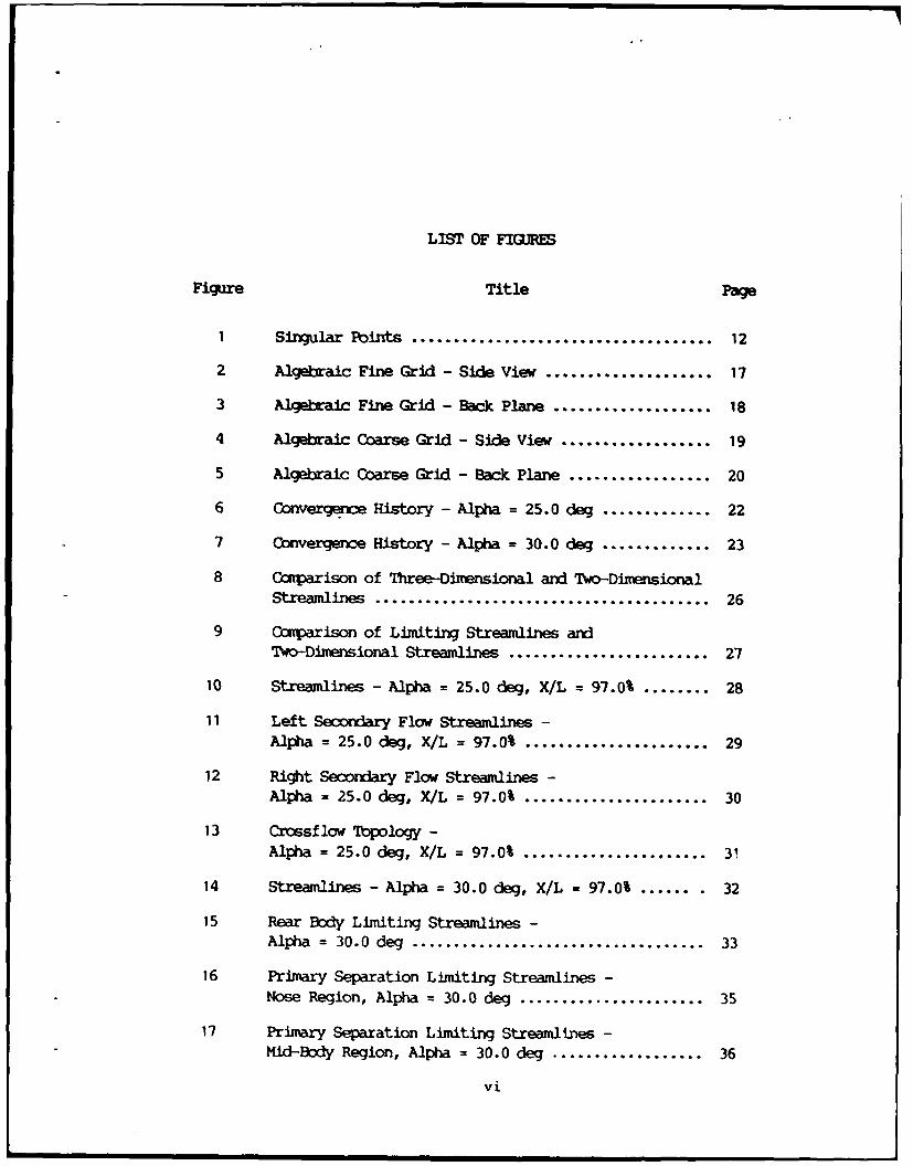
LIST OF FIGURES
Figure Title Page
I Singular Points ............................ 12
2 Algebraic Fine Grid - Side View ................... 17
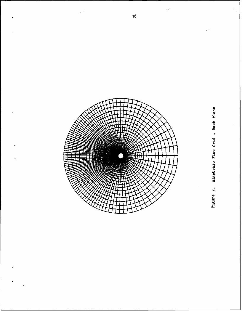
3 Algebraic Fine Grid - Back Plane.................. 18
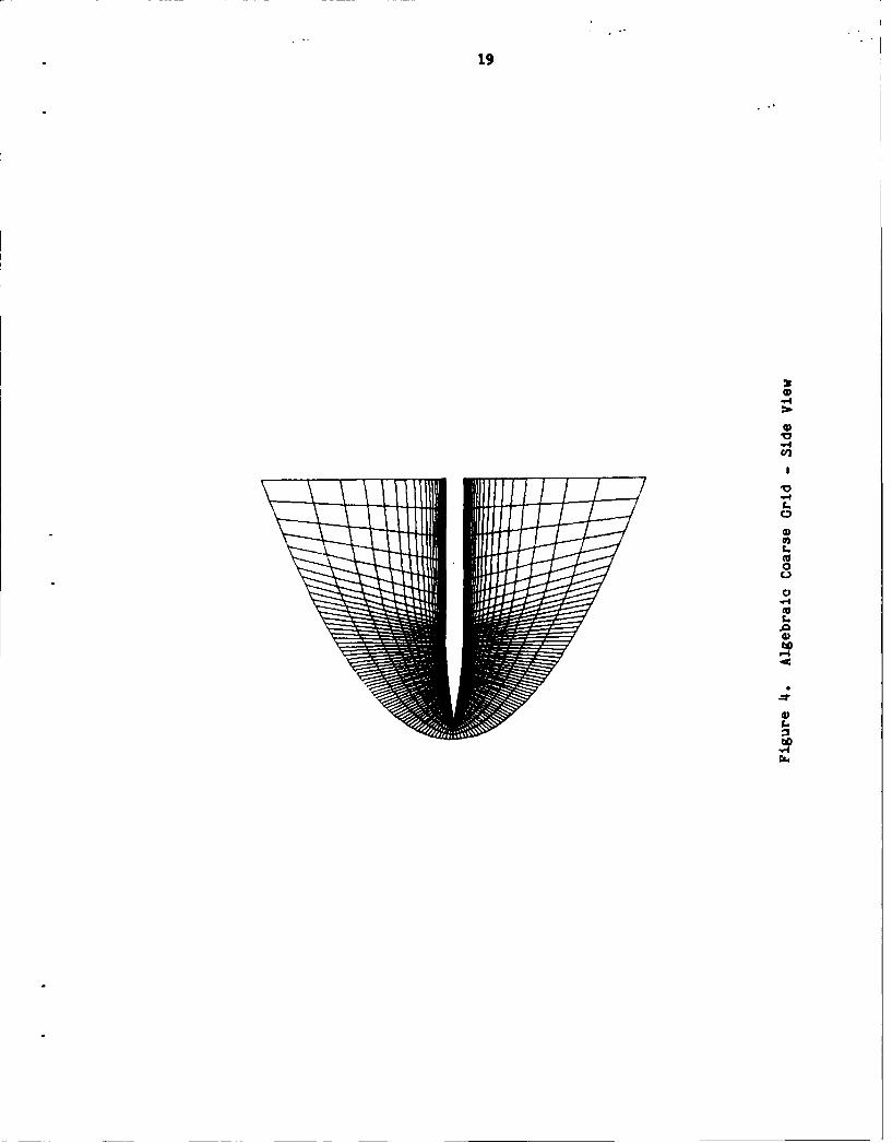
4 Algebraic Coarse Grid - Side View ................. 19
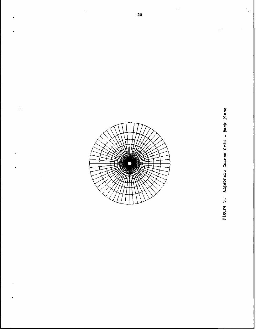
5 Algebraic Coarse Grid - Back Plane ................ 20
6 Convergence History - Alpha = 25.0 deg ............. 22
7 Convergence History - Alpha = 30.0 deg ............. 23
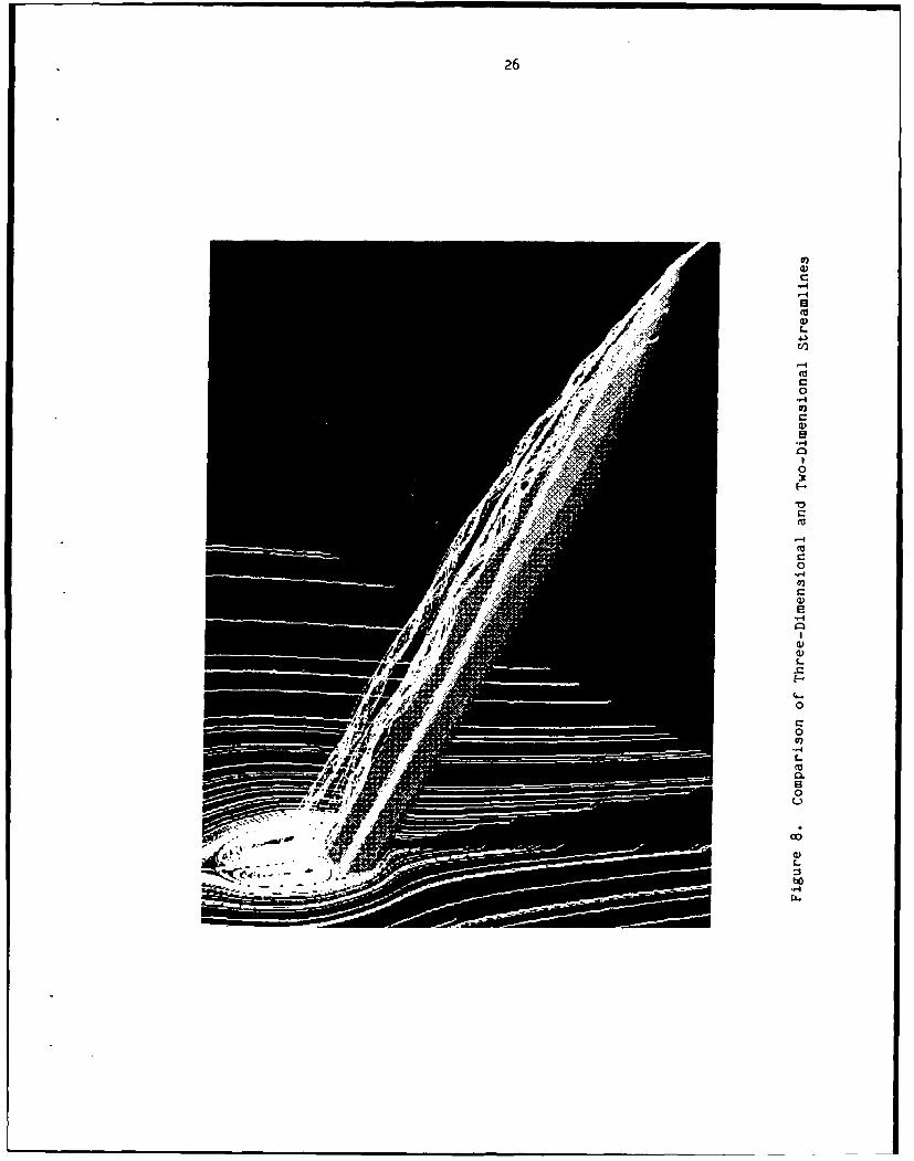
8 Corparison of Three-Dimensional and wo-DimensionalStreamlines .................................. 26
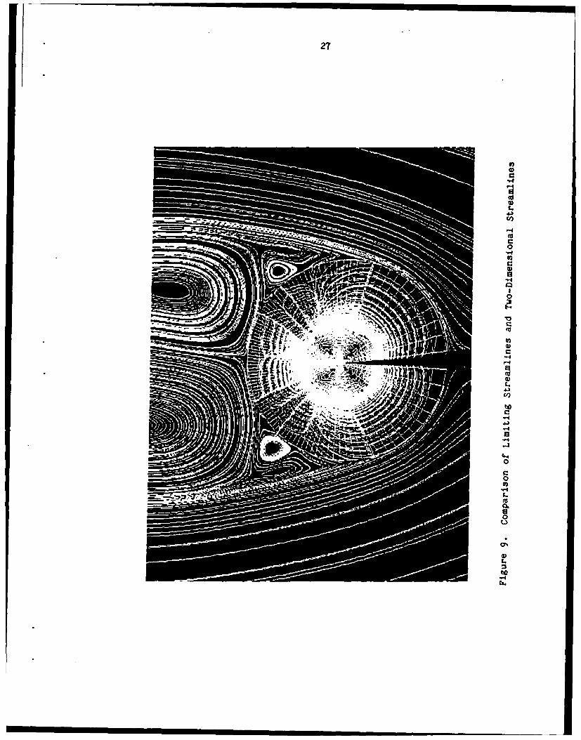
9 Caparison of Limiting Streamlines and
Two-Digensional Streamlines ....................... 27
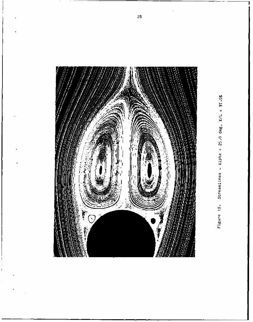
10 Streamlines -Alpha = 25.0 deg, X/L = 97.0% ........ 28
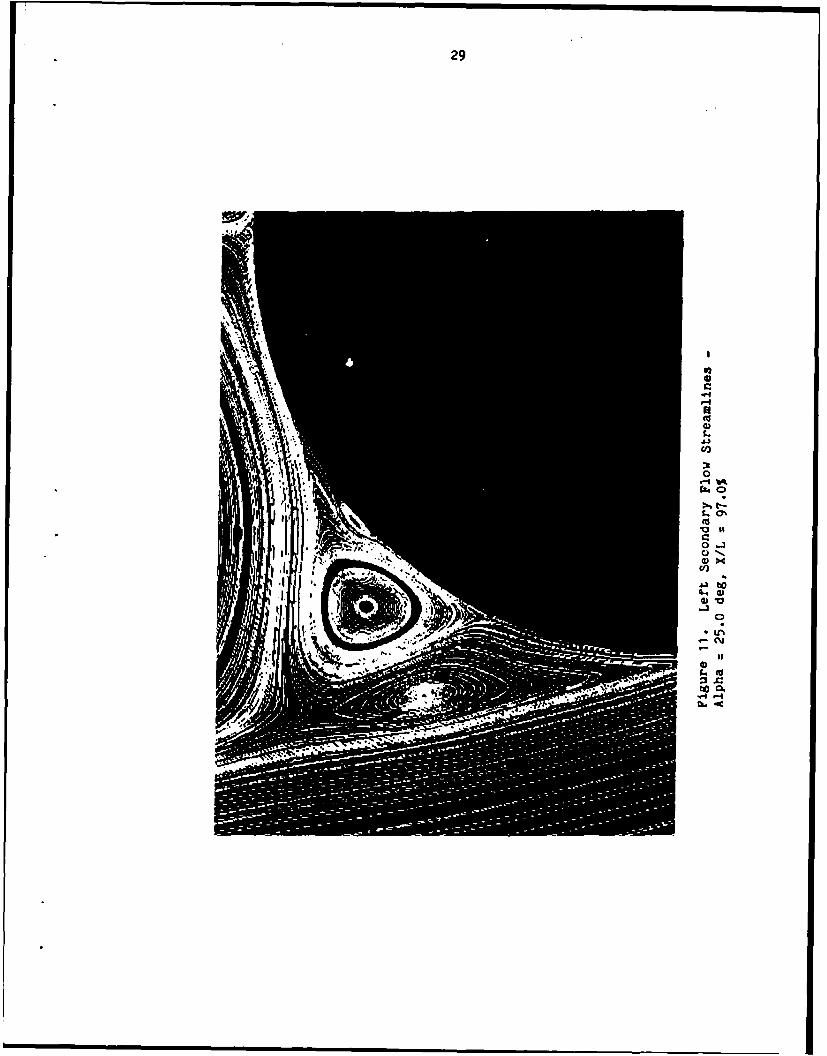
11 Left Secondary Flow Streamlines -Alpha = 25.0 deg, X/L = 97.0% ...................... 29
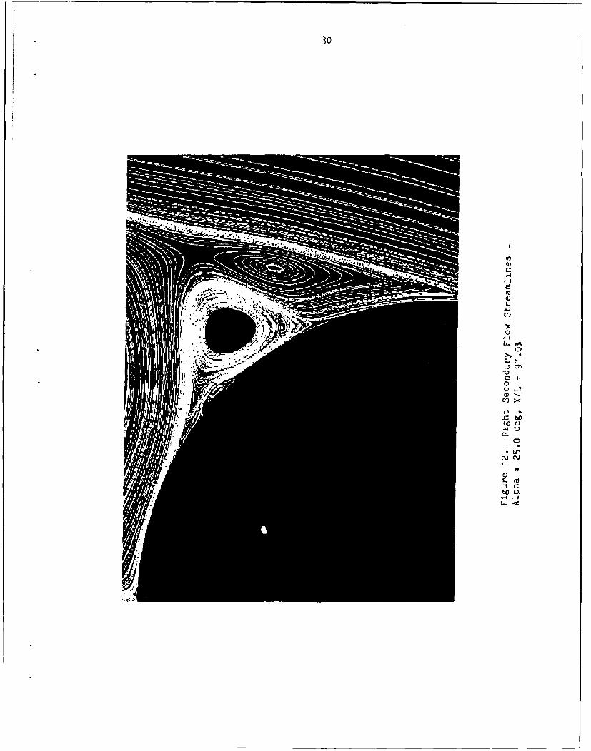
12 Right Secondary Flow Streamlines -Alpha = 25.0 deg, X/L = 97.0% ...................... 30
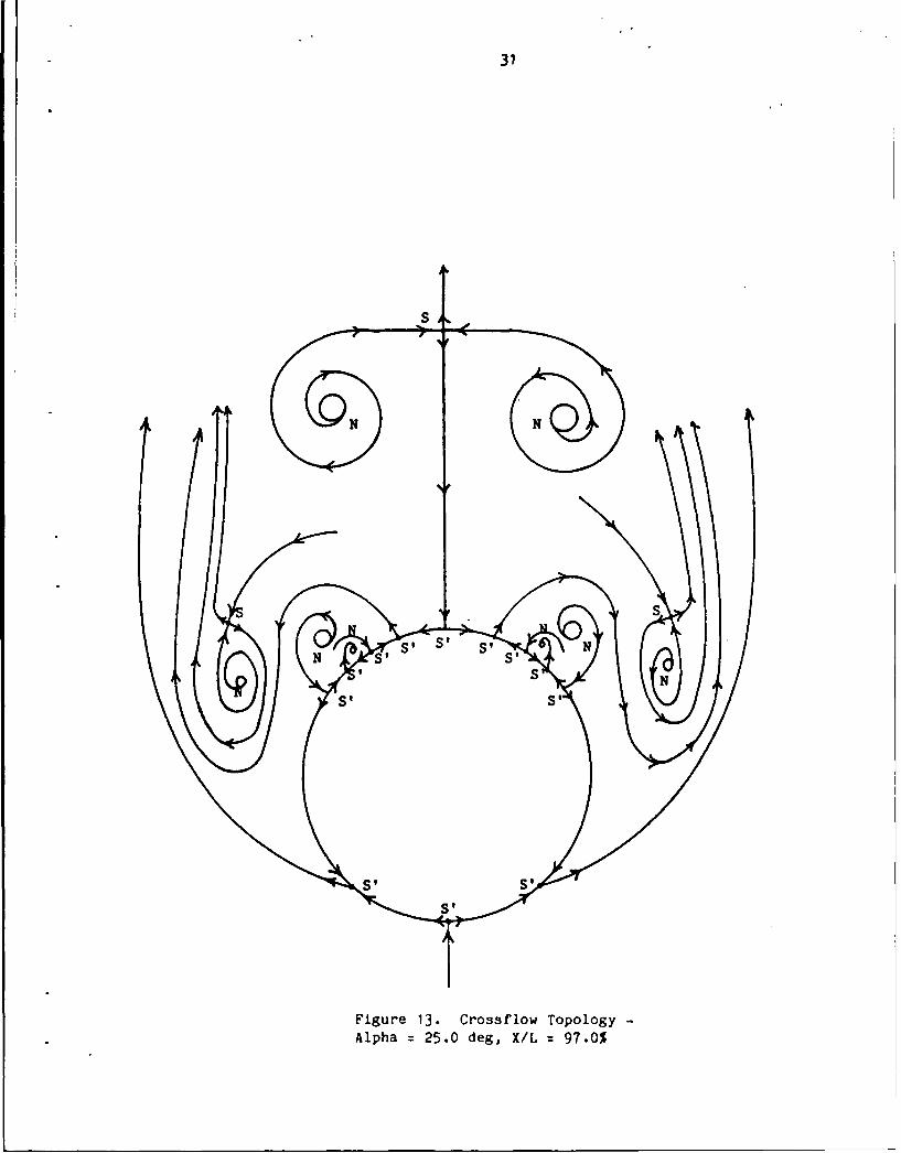
13 Crossflow Topology -Alpha = 25.0 deg, X/L = 97.0% ...................... 31
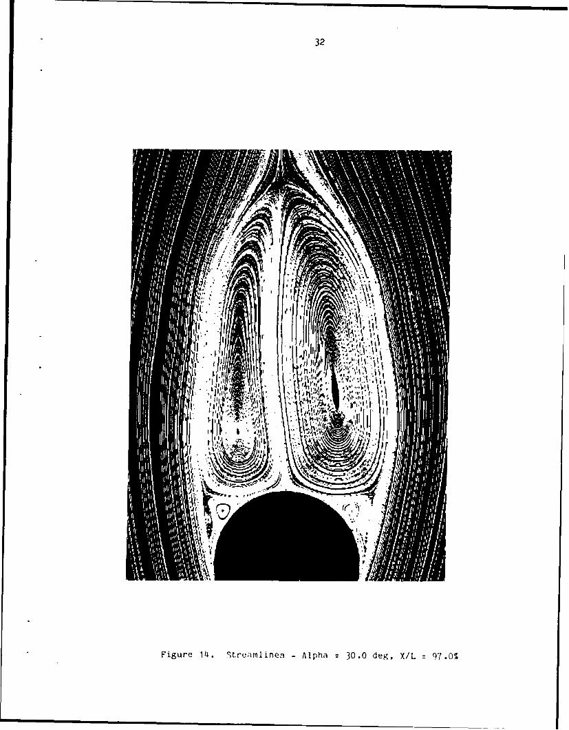
14 Streamlines - Alpha = 30.0 deg, X/L = 97.0% ....... 32
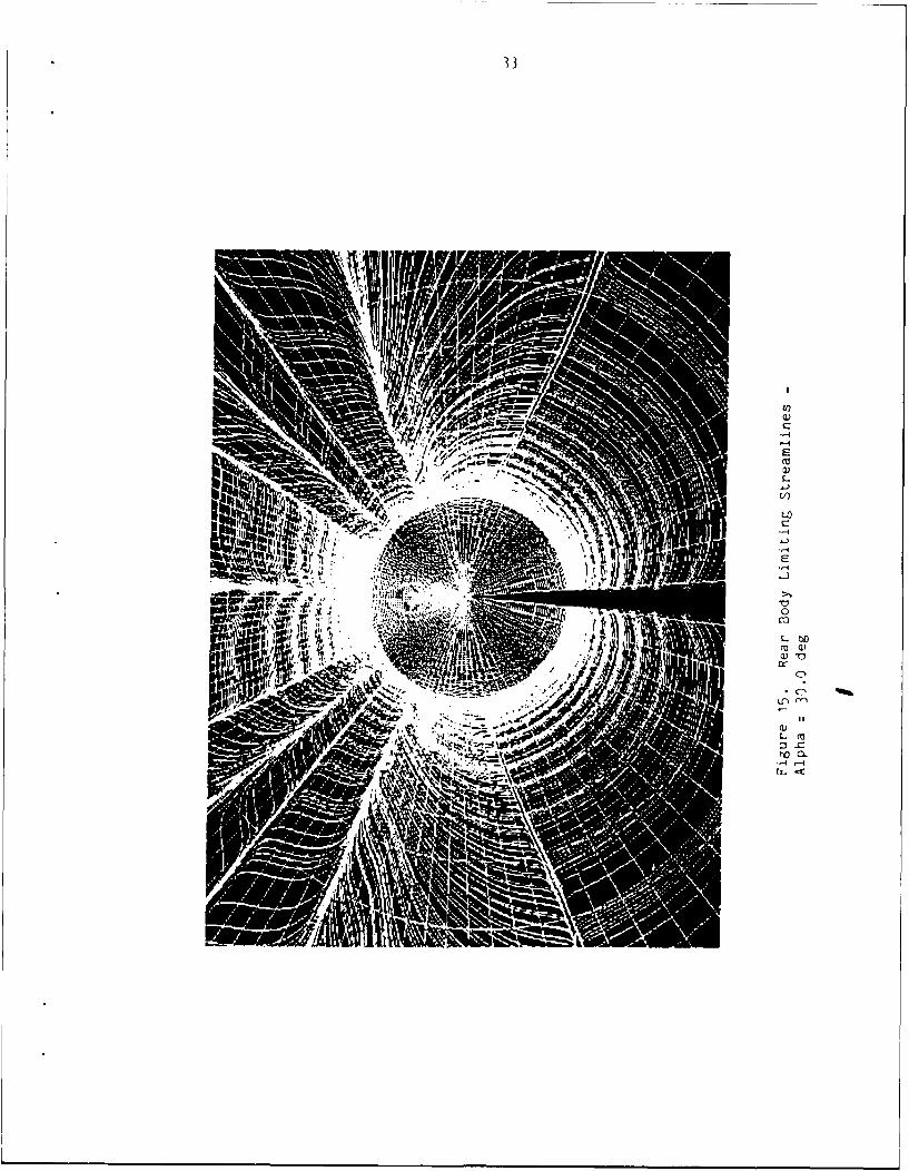
15 Rear Body Limiting Streamlines -Alpha = 30.0 deg ................................... 33
16 Primary Separation Limiting Streamlines -Nose Region, Alpha = 30.0 deg ...................... 35
17 Primary Separation Limiting Streamlines -Mid-Body Region, Alpha = 30.0 deg .................. 36
vi
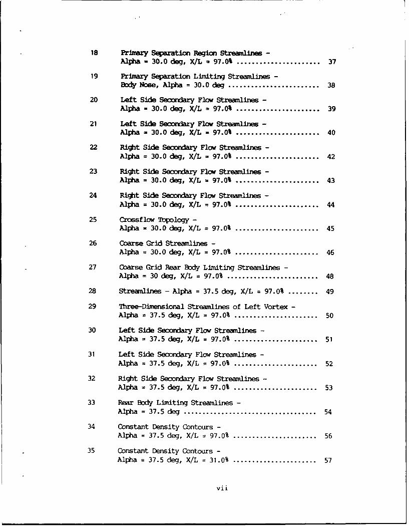
18 Primary Separation Region Streamlines -
Alpha - 30.0 deg, X/L - 97.0% ...................... 37
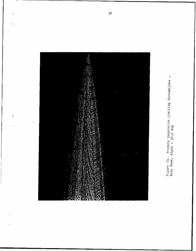
19 Primary Separation Limiting Streamlines -Body Nose, Alpha = 30.0 deg ....................... 38
20 Left Side Secondary Flow Streamlines -Alpha a- 30.0 deg, X/L = 97.0% ...................... 39
21 Left Side Secondary Flow Streamlines -Alpha - 30.0 deg, X/L - 97.0% ...................... 40
22 Right Side Secondary Flow Streamlines -Alpia = 30.0 deg, X/L = 97.0% ..................... 42
23 Right Side Secondary Flow Streamlines -Alpia - 30.0 deg, X/L = 97.0% ...................... 43
24 Right Side Secondary Flow Streamlines -Alpha = 30.0 deg, X/L = 97.0% ...................... 44
25 crossflow Topology -Alpha = 30.0 deg, X/L = 97.0% ...................... 45
26 Coarse Grid Streamlines -Alpha = 30.0 deg, X/L = 97.0% ...................... 46
27 Coarse Grid Rear Body Limiting Streamlines -
Alpha = 30 deg, X/L =97.0% ........................ 48
28 Streamlines - Alpha = 37.5 deg, X/L = 97.0% ........ 49
29 Three-Dimensional Streamlines of Left Vortex -Alpha = 37.5 deg, X/L = 97.0% ...................... 50
30 Left Side Secondary Flow Streamlines -Alpha = 37.5 deg, X/L = 97.0% ...................... 51
31 Left Side Secondary Flow Streamlines -Alpha = 37.5 deg, X/L = 97.0% ...................... 52
32 Right Side Secondary Flow Streamlines -Alpha = 37.5 deg, X/L = 97.0% ...................... 53
33 Rear Body Limiting Streamlines -Alpha = 37.5 deg ................................... 54
34 Constant Density Contours -Alpha = 37.5 deg, X/L = 97.0% ...................... 56
35 Constant Density Contours -Alpha = 37.5 deg, X/L = 31.0% ...................... 57
vii
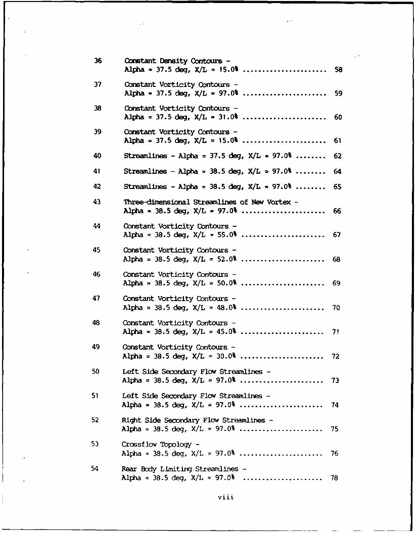
36 Corstant Density Contours -Alpha = 37.5 deg, X/L = 15.0% ...................... 58
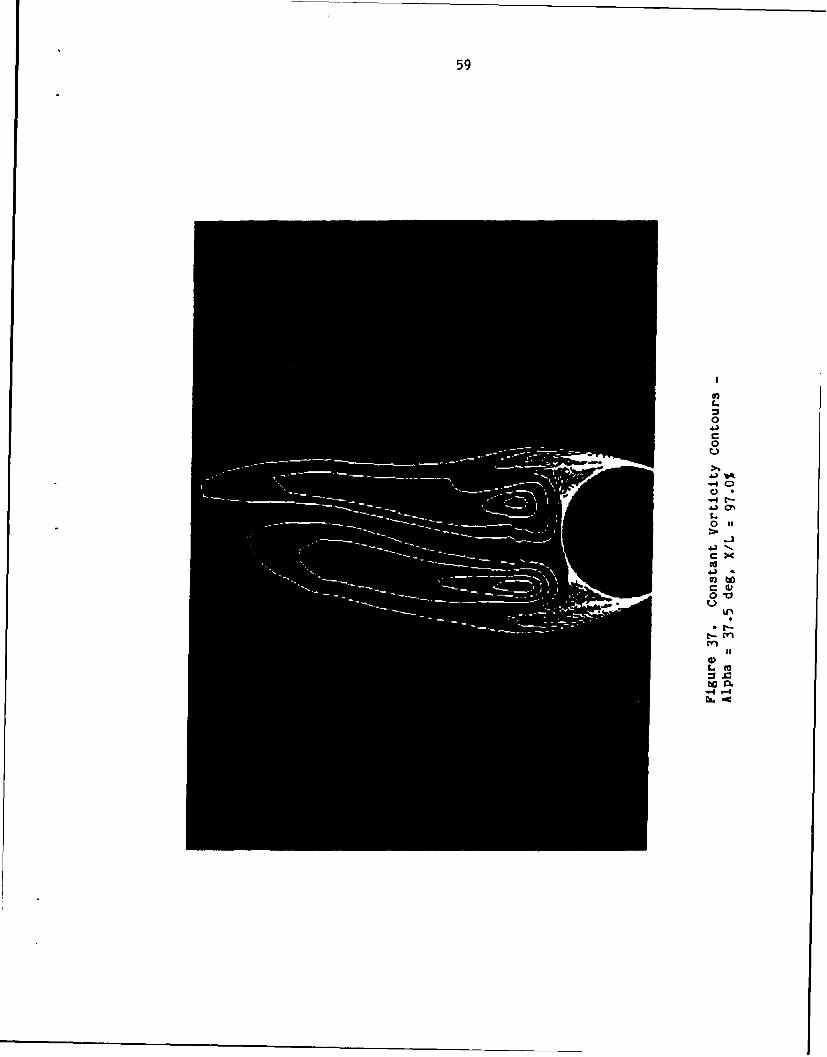
37 Constant Vorticity Contours -Alpha = 37.5 deg, X/L = 97.0% ...................... 59
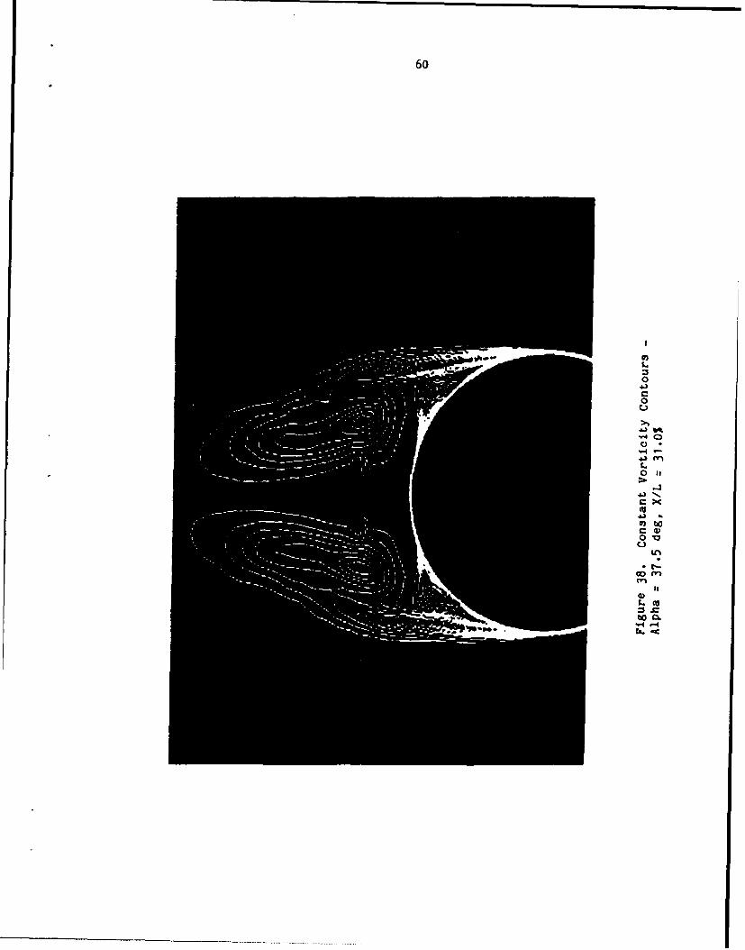
38 Constant Vorticity Contours -Alpha = 37.5 deg, X/L = 31.0% ...................... 60
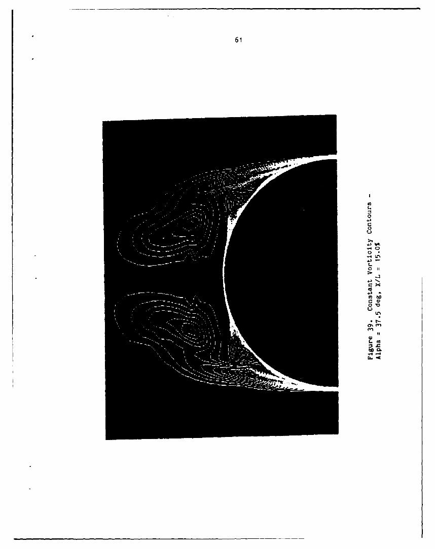
39 Constant Vorticity Contours -Alpha = 37.5 deg, X/L = 15.0% ...................... 61
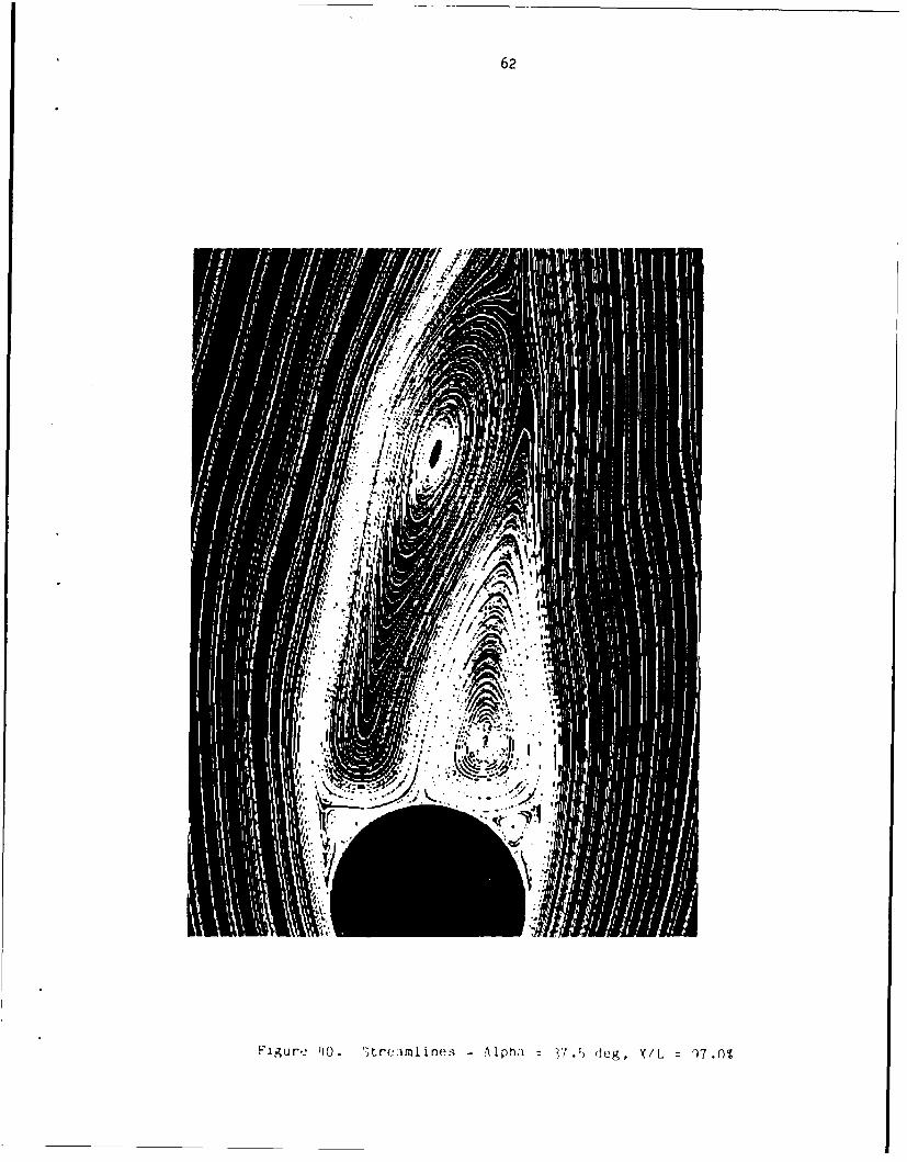
40 Streamlines - Alpha = 37.5 deg, X/L - 97.0% ........ 62
41 Streamlines - Alpha = 38.5 deg, X/L = 97.0% ........ 64
42 Streamlines - Alpha = 38.5 deg, X/L = 97.0% ........ 65
43 Three-dlmensional Streamlines of New Vortex -Alpha = 38.5 deg, X/L = 97.0% ...................... 66
44 Constant Vorticity Contours -Alpha = 38.5 deg, X/L = 55.0% ...................... 67
45 Constant Vorticity Contours -Alpha = 38.5 deg, X/L = 52.0% ...................... 68
46 Constant Vorticity Contours -Alpha = 38.5 deg, X/L = 50.0% ...................... 69
47 Constant Vorticity Contours -Alpha = 38.5 deg, X/L = 48.0% ...................... 70
48 Constant Vorticity Contours -Alpha = 38.5 deg, X/L = 45.0% ...................... 71
49 Constant Vorticity Contours -Alpha = 38.5 deg, X/L = 30.0% ...................... 72
50 Left Side Secondary Flow Streamlines -Alpha = 38.5 deg, X/L = 97.0% ...................... 73
51 Left Side Secondary Flow Streamlines -Alpha = 38.5 deg, X/L = 97.0% ...................... 74
52 Right Side Secondary Flow Streamlines -Alpha = 38.5 deg, X/L = 97.0% ...................... 75
53 Crossflow Topology -Alpha = 38.5 deg, X/L = 97.0% ...................... 76
54 Rear Body Limiting Streamlines -Alpha = 38.5 deg, X/L = 97.0% ..................... 78
viii
55 Strealines - Alpha - 40.0 deg, X/L - 97.0% ........ 79
56 Right Side Sewndary Flow Streamlines -Alpha = 40.0 deg, X/L = 97.0% ...................... 80
57 Left Side Secondary Flow Streamlines -Alpha - 40.0 deg, X/L = 97.0% ...................... 81
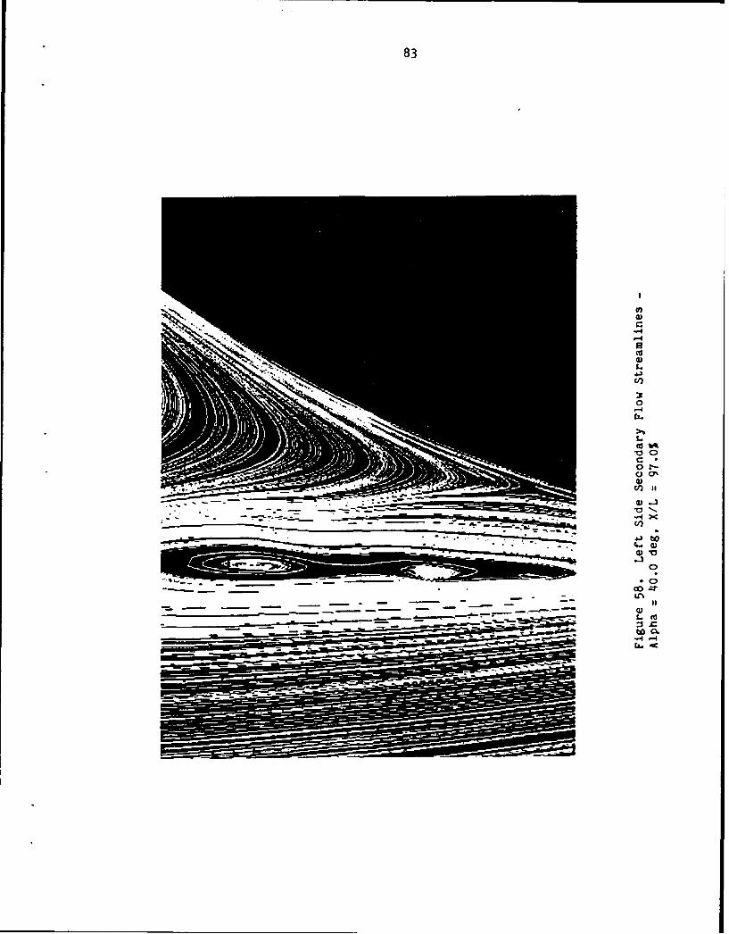
58 Left Side Secxdary Flow Streamlines -Alpha = 40.0 dog, X/L = 97.0%..................... 83
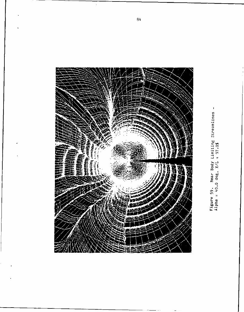
59 Rear Body Limiting Streamlines -Alpha = 40.0 deg, X/L = 97.0% ...................... 84
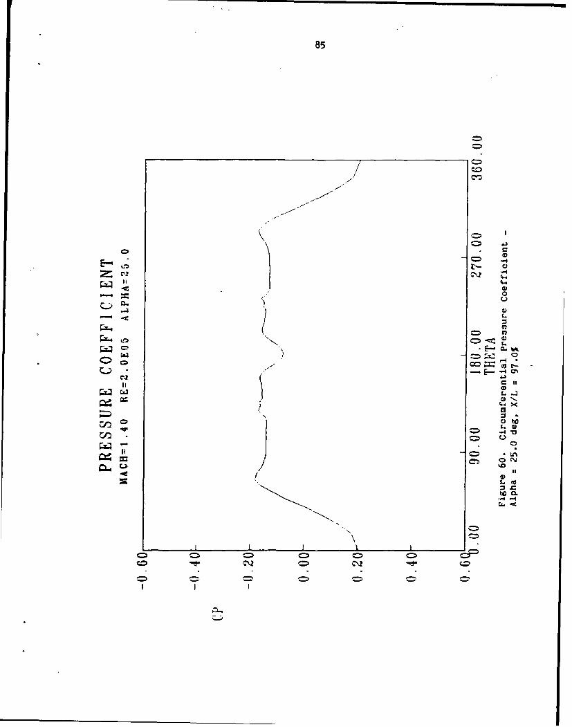
60 Circumferential Pressure Coefficient -Alpha = 25.0 deg, X/L = 97.0% ...................... 85
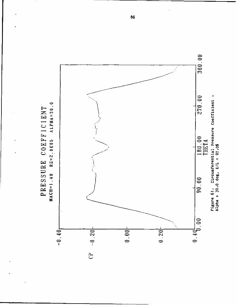
61 Circumferential Pressure Coefficient -Alpha - 30.0 dog, X/L = 97.0% ...................... 86
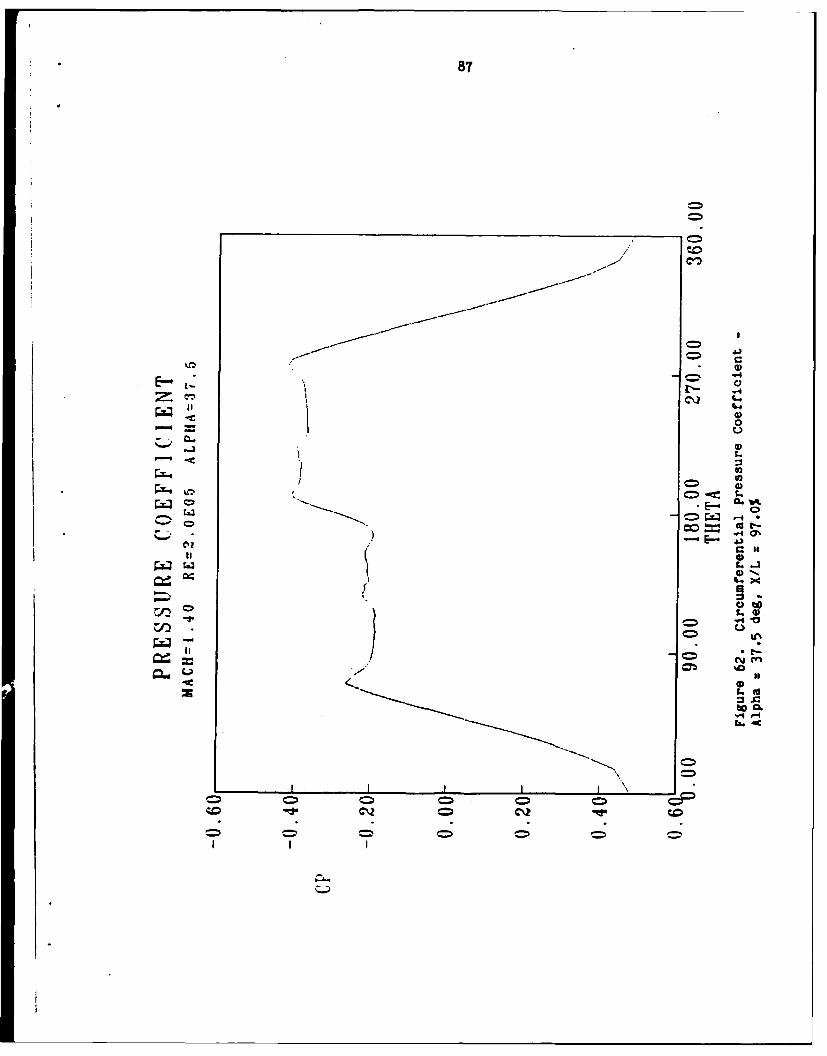
62 Circumferential Pressure Coefficient -Alpha = 37.5 deg, X/L = 97.0% ...................... 87
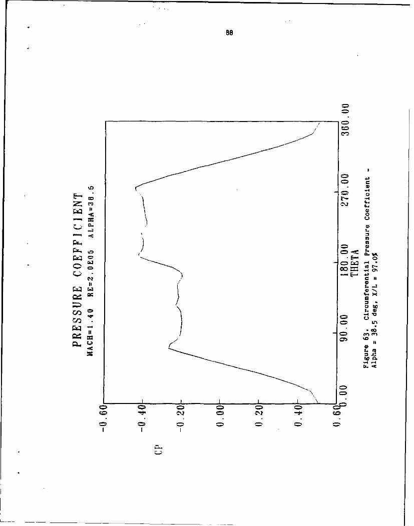
63 Circumferential Pressure Coefficient -Alpha = 38.5 deg, X/L = 97.0% ..................... 88
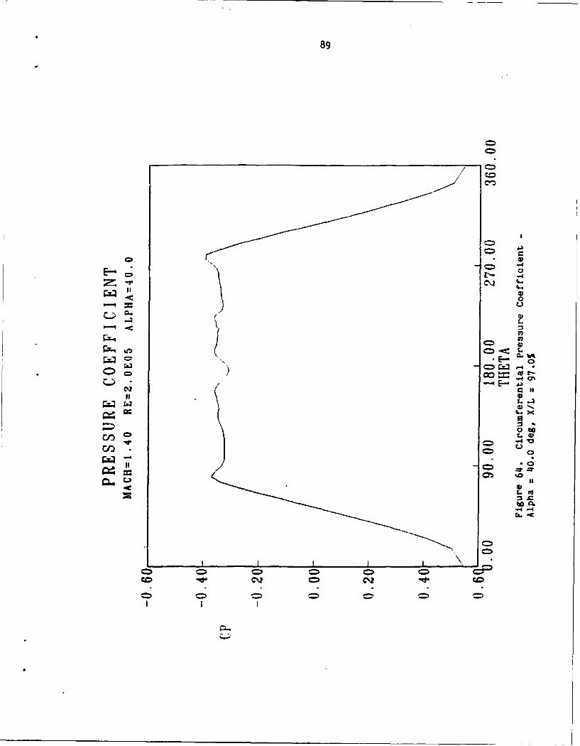
64 Circumferential Pressure Coefficient -Alpha = 40.0 deg, X/L = 97.0% ...................... 89
ix
ME TO SYMB
a. freestrem speed of sound
c local speed of sound
CEL Courant numter
e total specific energy
F,G,H curvilinear coordinate flux vectors
Gdiffusive flux vector
J metric Jacbian (cell volume)
1 reference length
L length of body
M Mach number
N nodal point
n normal coordinate
P pressure
Pr Prandtl number
q heat flux
Q curvilinear coordinate dependent variable vector
Re Reynolds number
S saddle point
t time
T temperature
u,v,w Cartesian velocity ccmponents
U,V,W contravariant velocities
V freestream velocityx
x,y, z cartesian coordinates
angle of attack
side slip angle
y ratio of specific heats
p density
fluid dynamic viscosity
V fluid kinematic viscosity
T transformed time variable, fluid stress vector
,, Tcurvilinear coordinates
vorticity
Subscripts
i,j,k grid point location
L laminar
GO freestream values
E 0) partial differentiation
x,y,z partial differentiation
Superscripts
n time level
half singular point
xi
amPTE I
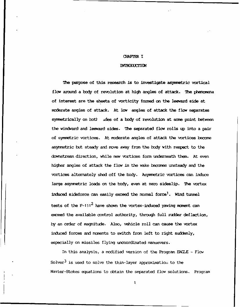
The purpose of this research is to investigate asymnetric vortical
flow around a body of revolution at high angles of attack. The phenzena
of interest are the sheets of vorticity forned on the leeward side at
noderate angles of attack. At low angles of attack the flow separates
symmetrically on botl ides of a body of revolution at soae point between
the windward and leeward sides. The separated flow rolls up into a pair
of symnetric vortices. At moderate angles of attack the vortices become
asymmetric but steady and move away from the body with respect to the
downstream direction, while new vortices form underneath them. At even
higher angles of attack the flow in the wake becoes unsteady and the
vortices alternately shed off the body. Asymwetric vortices can induce
large asynmetric loads on the body, even at zero sideslip. The vortex
induced sideforce can easily exceed the normal force1 . Wind tunnel
tests of the F-i 112 have shown the vortex-induced yawing maent can
exceed the available control authority, through full rudder deflection,
by an order of magnitude. Also, vehicle roll can cause the vortex
induced forces and moents to switch fran left to right suddenly,
especially on missiles flying uncoordinated manuevers.
In this analysis, a modified version of the Program EAGLE - Flow
Solver 3 is used to solve the thin-layer approximation to the
Navier-Stokes equations to obtain the separated flow solutions. Program
I
2
EMLE - Grid Generator is used to construct the algeraic grid. This
research uses a framework for the observation of aerodynamic flows which
stresses physical features and descriptive mathematcs 4 . To provide
a systematic and rigorous base to this framework the mathunatics of
topology is used. Topology had its beginning in the oervation that
there are a number of geometrical properties that are unchanged by
continuous deformations. The use of topology in aerodynamics was first
introduced systematically by Legendre 5 , who noted that the irportant
structures of the flow can be described by a finite number of singular
(critical) points which must conform to summation rules. The topology of
singular points has proved to be a very useful tool in analyzing skin-
friction patterns and streamlines from experimental studies or numerical
calculations.
Experimental studies of asymmetric vortex flow have been conducted
by many researchers. Lamont 6 performed low Mach number wind tunnel
tests of an ogive-cylinder and identified two mechanisms for producing
asymmetric flow. One mechanism operates in the fully laminar or fully
turbulent regime and is qualitatively described by the impulsive flow
analogy. The second mechanism observed was in transitional flow and is
analogous to the two-dimensional crossflow on a circular cylinder in the
transitional separation regime. Yanta 7 et al. performed wind tunnel
tests of a tangent ogive in low turbulence inccopressible flow with
asymmetric vortices. These results supported hydrodynamic instability as
being a cause of vortex asymetry. The leeside flow was examined in
detail including the streamlines and singular points on two-dimensional
cross sections of the flow. The effect of nose bluntness was found to
have no effect on the basic qualitative topological structure in the
3
crossf low plane. Keener 8 corxkted subsonic and supersonic wind
tunnel tests of ogival, parabolic, and conical forebodies over a wide
range of Reynolds numbers. The principle cause of vortex asymmetry was
also found to be the hydrodynamic instability of the inviscid flow field
with additional asymmetry being observed in the boundary layer at
transitional conditions. Nose bluntness was observed to add additional
structure in one case. An additional vortex pair, not observed on sharp
nosed ogives, was observed above the primary vortices on a blunted ogive
forebody. These vortices were believed to be generated at the nose.
Chapman 4 discusses the topology of bodies of revolution in general
and notes that, except for crossflow shocks, the topology is basically
the same for both subsonic and supersonic flows. Keener 9 et al. and
Keener and Chapman 1 0 have conducted wind tunnel measurements
of asymetric induced forces and moments on various bodies of revolution
for both subsonic and supersonic flows, with the former study noting that
as the Mach number approaches supersonic values the vortex-induced side
force approaches zero. The control of vortex orientation has been
investigated by Peake 11 et al. using injection of air near the
nose, and by Fidler 12 who used rotation of the nose region.
Several numerical investigations have also been done.
Ying1 3 et al. conducted transonic laminar thin-layer
Navier-Stokes calculations of the asynmetric vortical flow on a
hemisphere cylinder and studied the connection between surface flow
topology and the surfaces of separation. More recently, Siclari and
Marconi 1 4 calculated supersonic laminar formation of steady
asymetric vortices on a cone. These calculations were converged to
machine zero using a Navier-Stokes algorithm modified with the assumption
14
of conical flow.
In this thesis, details of the secondary flow associated with
asymmetric vortex flow are numerically investigated and found to agree
qualitatively with previous experimental results. In adition, the
crossflow topology for a number of angles of attack is given to
illustrate the difference between symmitric flow and various asymmetric
flows.
A description of the governing equations and the numerical algorithm
is given in Chapter II followed by a description of the use of topology
in the analysis of fluid flows in Chapter III. The numerical grids and
convergence history are given in Chapter IV. Finally, Chapter V presents
and discusses the results of the calulations performed.
CHAPER II
FLOWI SOLVR
The boudary-layer equations are useful for many different types of
viscous flows. However, there are many problems in which the boudary-
layer assumption is not valid and a more exact form of the Navier-Stoces
equations must be used. The current problem of the high angle-of-attack
flow over a body of revolution is an example. The thin-layer
approximation to the complete Navier-Stokes equations is particularly
useful in this case since separated and reverse flow regions can still be
computed but with a significant decrease in comtpitational requirements.
In the formal derivation of the unsteady boundary-layer equations all
terns on the order of I/(ReL )/2 and smaller are neglected. This
results in the viscous terns containing derivatives in the directions
parallel to the body being dropped since they are significantly smaller
than the viscous term normal to the boundary. In addition, the momentum
equation is reduced to a simpler equation in which the pressure normal to
the wall is constant. In the thin-layer aproximation the viscous terms
parallel to the body are dropped again, but all other terms of the
ntnentum equation are retained. The thin-layer Navier-Stokes equations
are a mixed set of hyperbolic-parabolic partial differential equations.
The thin-layer Navier-Stokes Program EAGLE flow solver calculates the
viscous term explicitly and implements them after the inviscid terms
have been calculated in an implicit upwind method. The inviscid portion
of the algorithm optionally uses either flux-vector split or flux-
difference split finite-volume formulations. By computing the viscous
terms explicitly the cost of the thin-layer algorithm is only about
5
6
15% greater than the Euler algorithm on an idntical grid. This is due
to the separate calculation of the inviscid terms for which upwind
differencing is most effective. Whitfield15 developed the
baseline algorithm with flux-vector splitting, Belk and Whitfield16
extended it to obtain time-accurate solutions on multi-blocck grids, and
Gatlin and Whitfield17 added the thin-layer a pximation.
The version of the Program EAGLE flow solver used in this study was
further modified by Sinpson1 8 to include a flux-difference
splitting scheme due to Roe 1 9. This scheme was used for all
calculations performed.
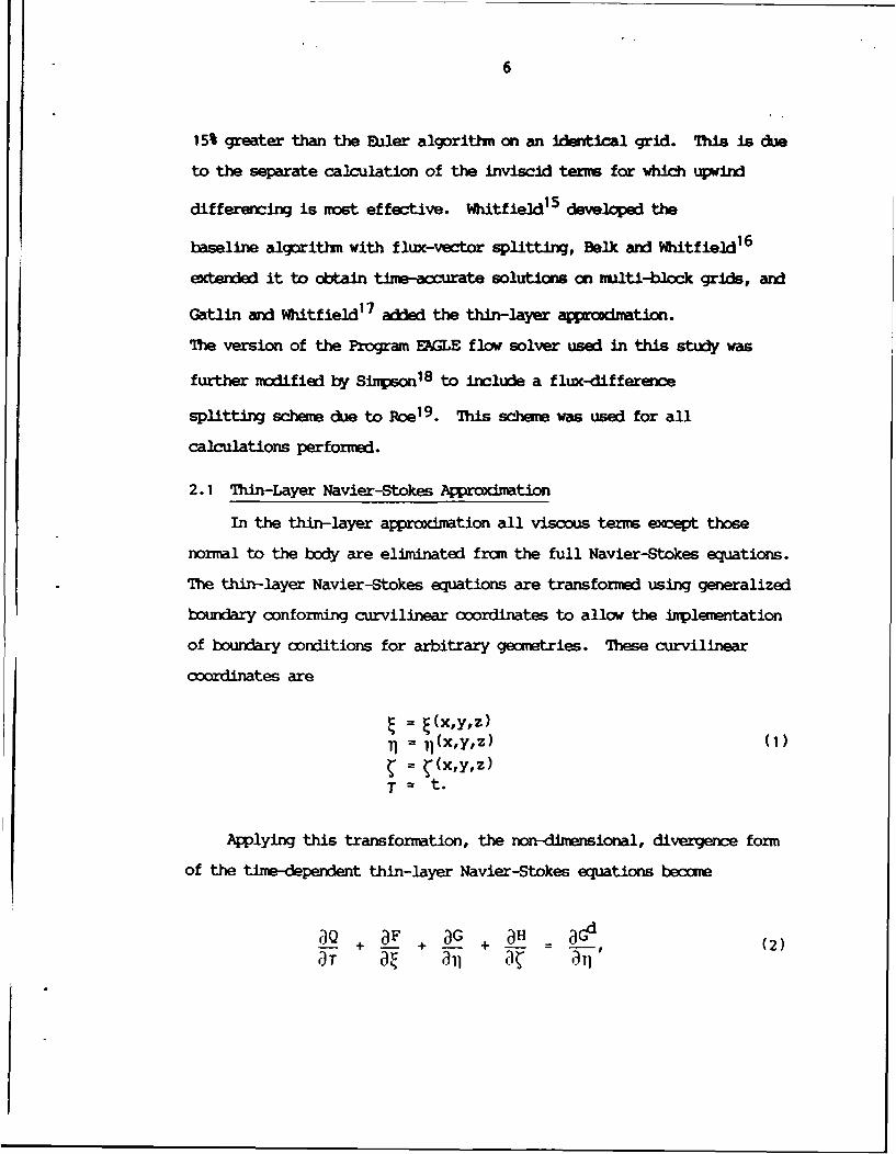
2.1 Thin-Layer Navier-Stokes Aproximation
In the thin-layer approxbiation all viscous tenm except those
normal to the body are eliminated fran the full Navier-Stokes equations.
The thin-layer Navier-Stokes equations are transformed using generalized
boundary conforming curvilinear coordinates to allow the implementation
of boundary conditions for arbitrary gecmetries. These curvilinear
coordinates are
)= (x,y,z) (1)
S= 11(X'y' z)- (x,y,z)
T = t.
Applying this transformation, the non-dimensional, divergence form
of the time-dependent thin-layer Navier-Stokes equations beccue
()Q , d G , - ac'(2)
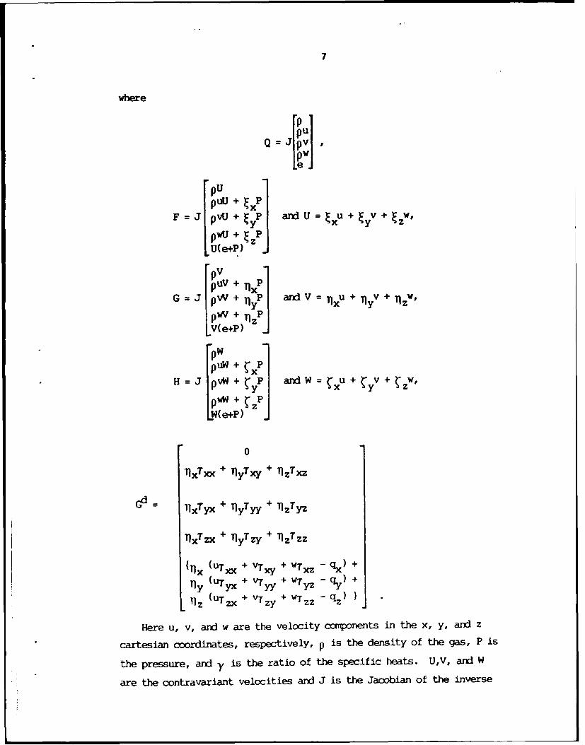
7
where
Q J vWjpU
PULJ + xP
F=J pvU + yP andU x U u+Eyv + W,
pwU + E
U( e+P)
pVpUV + n e
G-J pV+q P and V-xu+yv+nw,PwV + TI z
V(e+P)pWPuw + x
H = j PVW + y w an W xu + yv + zw,
)WW + zP
LW(e+P)
0
T'xTxx + lyTx + llzTxz
= 11Tyx + YT , + TjzTyz
TxTzx + TyTzy + IjzTzz
{ (UTxx + VTxy + WTxz - qx) +
1y (UTyx + VTyy + WrTyz - qy) +
L1 z (uTzx + VTzy + WTzz - qz )
Here u, v, and w are the velocity ccsponents in the x, y, and z
cartesian coordinates, respectively, V is the density of the gas, P is
the pressure, and y is the ratio of the specific heats. U,V, and W
are the contravariant velocities and J is the Jacobian of the inverse
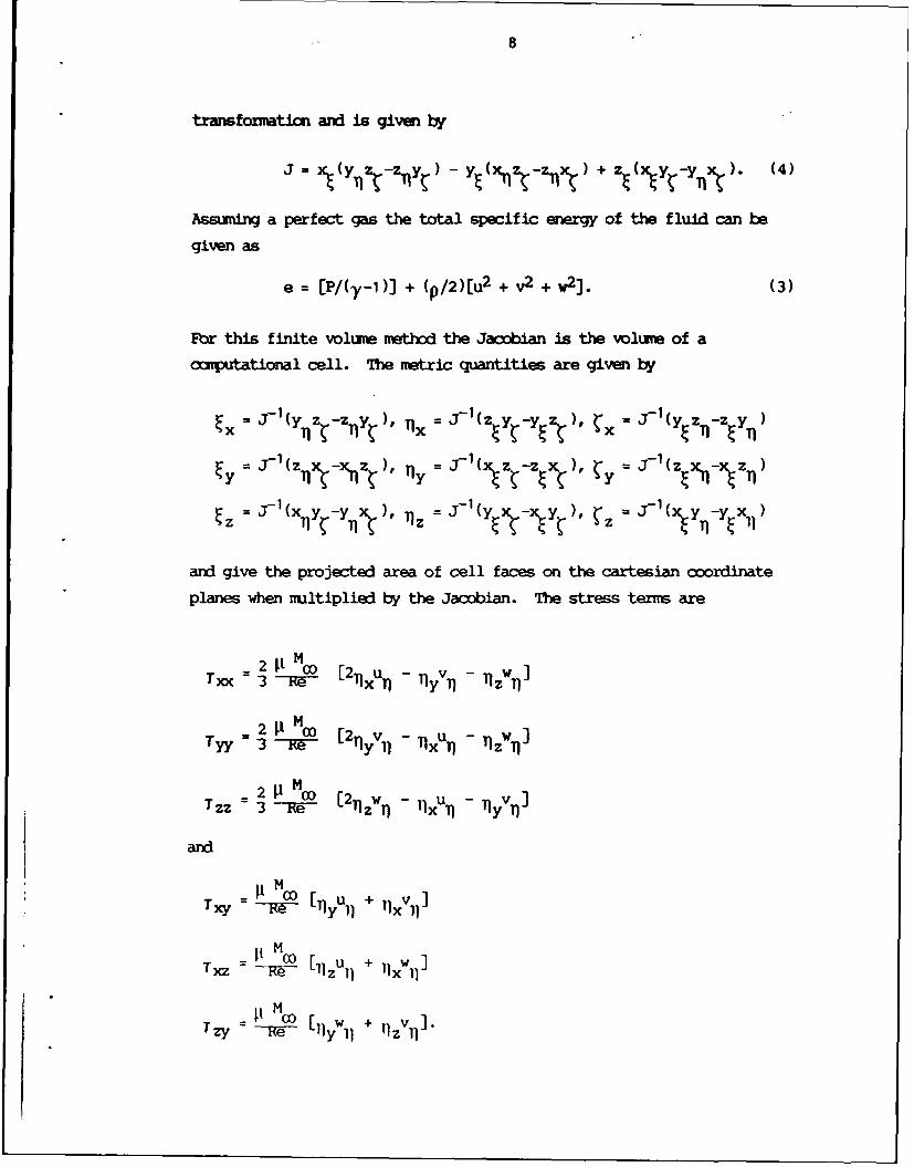
8
transformatin and is given by
J -= (yn k -Z'ny ) - YE N zn + ,(Xy,-yx,.). (4)
Assuming a perfect gas the total specific energy of the fluid can be
given as
e = [P/(y-1 )J + (p/2)[u 2 + v2 + w2]. (3)
Fbr this finite volume method the Jacobian is the volume of a
camputational cell. The metric quantities are given by
y = J-1' N x.z ), Tl = J1 (yze x), y = J1'(z x.1 -xy l)
Z ~ ~ = J y1 y = J 1( y -YEX11
and give the projected area of cell faces on the cartesian coordinate
planes when multiplied by the Jaxobian. The stress terms are
2 -- - v- Itw][
Tr 3- 1w- I A) - fl - vzW)J
2 . P MO 2Tyv, - qxuT - Tnzw]
and
M
I f l0yW + ]"rxz Re [lll+ lxll
T zy e-t CO lWl + Il
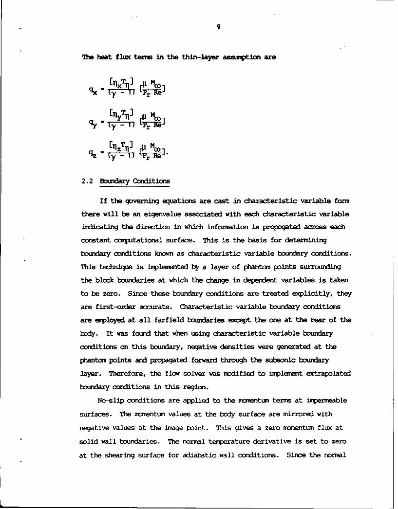
9
The heat flux terns in the thin-layer assmption are
q= - (
[(T-')
[yT1 Mi
qz ( - rpCC
2.2 Bundary Conditions
If the gpverning equations are cast in characteristic variable form
there will be an eigenvalue associated with each characteristic variable
indicating the direction in which information is propogated across each
constant cxmputational surface. This is the basis for determining
boundary conditions known as characteristic variable boundary conditions.
This technique is implemented by a layer of phantan points surrounding
the block boundaries at which the change in dependent variables is taken
to be zero. Since these boundary conditions are treated explicitly, they
are first-order accurate. Characteristic variable boundary conditions
are employed at all farfield boundaries except the one at the rear of the
body. It was found that when using characteristic variable boundary
conditions on this boundary, negative densities were generated at the
phantom points and propagated forward through the subsonic boundary
layer. Therefore, the flow solver was modified to implement extrapolated
boundary conditions in this region.
No-slip conditions are applied to the momentum term at impermeable
surfaces. The momentum values at the body surface are mirrored with
negative values at the image point. This gives a zero momentum flux at
solid wall boundaries. The normal temperature derivative is set to zero
at the shearing surface for adiabatic wall conditions. Since the normal
10
pressure gradient is assumed to be negligible at the solid wall, the
boundary conditions for energy ard density are given as
neIV=0 and %wn 0. (5)Fn anV
QF'RIII
TOPOVLOGY
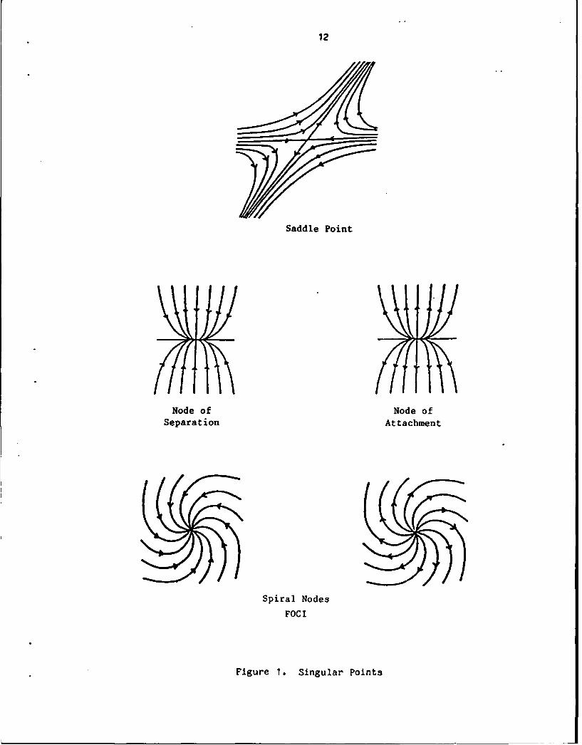
The mathtical basis for the behavior of the elementary
singular points of skin-friction lines and the topological rules
these points obey have been known for a long time. Davey2 and
Lightil12 1 were the first to point out that skin-friction lines
must obey a specific topological rule: the sum of nodal points
and foci must exceed the number of saddle points by two. Nodal
points, foci, and saddle points are examples of singular points
(Figure 1 ). Singular points are divided into two types known as
nodes and saddle points. Node points are further divided into
nodal points and foci. These singular points in the skin-
friction lines oocur at isolated locations on the surface where
the surface vorticity and skin-friction beme identically zero.
A nodal point is the point that is common to an infinite
number of skin-friction lines. All the lines associated with
that point, except one, are tangential to a single common line. At
a nodal point of separation, all the skin friction lines are
directed inward toward the node. At a nodal point of attachment,
all the skin-friction lines are directed away from the node. A
focus differs from a nodal point in that an infinite number of
skin-friction lines spiral around the singular points. The lines
spiral away from an attachment focus while a separation focus has
all the lines spiraling into it. The singular point associated
with a saddle point has only two skin-friction lines that pass
11
12
Saddle Point
Node of Node ofSeparation Attachment
Spiral Nodes
FOCI
Figure 1. Singular Points
13
through It. The halves of one line are directed inwards tzwards
the center while the halves of the remaining line are directed
outwards. These two lines act as barriers, making one set of
skin-frition lines inaccessible to an adjacent set.
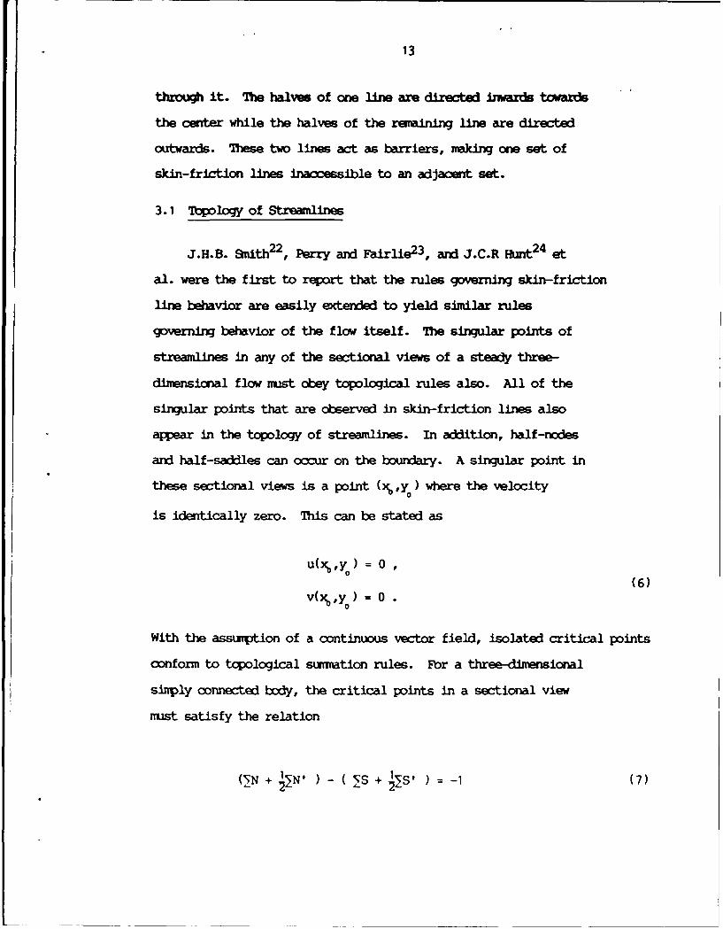
3.1 Topology of Streamlines
J.H.B. Smith2 2 , Perry and Fairlie 2 3 , and J.C.R Hunt 24 et
al. were the first to report that the rules governing skin-friction
line behavior are easily extended to yield similar rules
governing behavior of the flow itself. The singular points of
streamlines in any of the sectional views of a steady three-
dimensional flow must obey topological rules also. All of the
singular points that are observed in skin-friction lines also
appear in the topology of streamlines. In aadition, half-nodes
and half-saddles can occur on the boundary. A singular point in
these sectional views is a point (x%,y ) where the velocity
is identically zero. This can be stated as
u(x 'Y ) = 0(6)
v(x'Y ) = 0
With the assumption of a continuous vector field, isolated critical points
conform to topological summation rules. For a three-dimensional
simply connected body, the critical points in a sectional view
must satisfy the relation
(" N + N' )-(S +s 1 =- (7)
14
where N denotes nodes and S indicates saddles with the prims denoting
half singular points.
3.2 Tiology of Separation
Topology has also played a key role in defining the nature
of separated flows. '1bak and Peake2 5 have given a
definition of attached and separated flows in which they define
two types of separation called global and local. An attached
flow is defined as a flow containing two and only two singular
points in the skin-friction lines. These two points are a nodal
point of attachment and a nodal point of separation. Global
separation occurs when the skin-friction patterns contain more
than two nodal points. For every nodal point over two a saddle
point mist exist. This topological rule is stated as
2N - 2S = 2 (8)
For example, when the flow contains three nodal points of which
two must be the same type the lines emanating from these alike
nodal points mist be prevented from crossing. The separatrixes
of a saddle point provide the needed barrier. A separation line
is defined as one of these two separatrixes. 7b summarize Tobak
and Peake 2 5 , skin-friction lines for attached flow cannot
contain any saddle points, while they must contain at least one
saddle point in globally separated flow.
Crossflow separation, however, does not always obey this
topological rule. The skin-friction lines on a body with only a
crossflow type of separation contain only lines connecting the
nodal point of attachment at the nose with the nodal point of
15
separation at the rear. This is the sam topolog l
that exists without crossflow separation. Even though no
separation saddle point exists, converging streamlines can
squeeze together at a rate that forces the fluid away fram the
body. The line on which the limiting streamlines eventually
converge apears to emerge from the region of the attachndt node
on the nose. This type of separation is known as local
separation. The concept of limiting streamlines, first used by
Sears 2 6 a later extee by Lgendre2 7 , becmeii
for determining the point at which the flow is forced away fran
the body. Limiting streamlines are streamlines that, exept near
flow separation, exist infinitesimally close to the surface of the
body and their direction is the same as the skin-friction lines.
Therefore, the limiting streamlines can be viewed as a surface of
streamlines whose projection on the body are skin-friction lines.
Limiting streamlines rising on either side of the line of
separation are prevented from crossing by a stream surface which
enanates fran the line of separation itself. On a body of
revolution the dividing surfaces usually roll up into vortices as
they progress downstream.
CHMYM IV
NUMICAL CALCJLATICNS
The configuration selected for this research is a five
caliber tangent ogive nose with a circular afterbody eight
diameters long. This configuration was selected because of the
wide range of experimental studies performed using tangent ogive
4.1 Numerical Grids
The grids used in this analysis were generated using the
Program EAGLE - Numerical Grid Generation System2 8
developed jointly by the Air Force Armament Laboratory's
CoMputational Fluid Dynamics Section and the Department of
Aerospace Engineering of Mississippi State University.
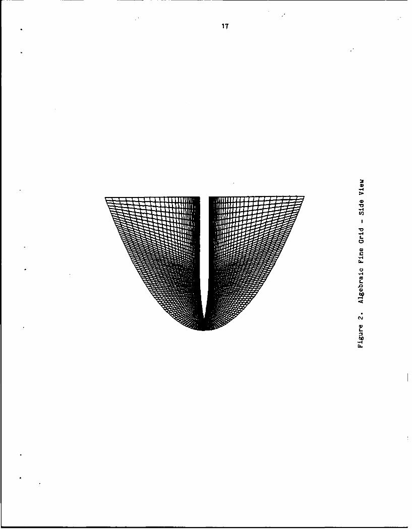
The single block algebraic fine grid (Figures 2 and 3) has
70 axial, 60 normal, and 100 circumferential points. This
equates to a total of 420,000 grid points. The thin-layer
Navier-Stokes solutions on this grid required over 114 million
words of core memory on the Cray-2 machine at the United States
Air Force SuperCcmputer Center-Kirtland(AISCC-K). This grid was
used for all calculations except for a grid refinement study. A
single block algebraic grid (Figures 4 and 5) with 60 axial, 50
normal, and 61 circumferential points was used for a grid
refinement study at 30.0 degrees angle of attack. The results of
16
17
14
V.4
C
-4
bn
.4
18
Jig
0
-4
cc
bo
19
0-4
SV-4C')
V-4L.
C,
S0L.00C)
C)-40
4,
4)L
-4b.
20
U
b4
-4rL.
21
the grid refinement study are discussed in the analysis chapter.
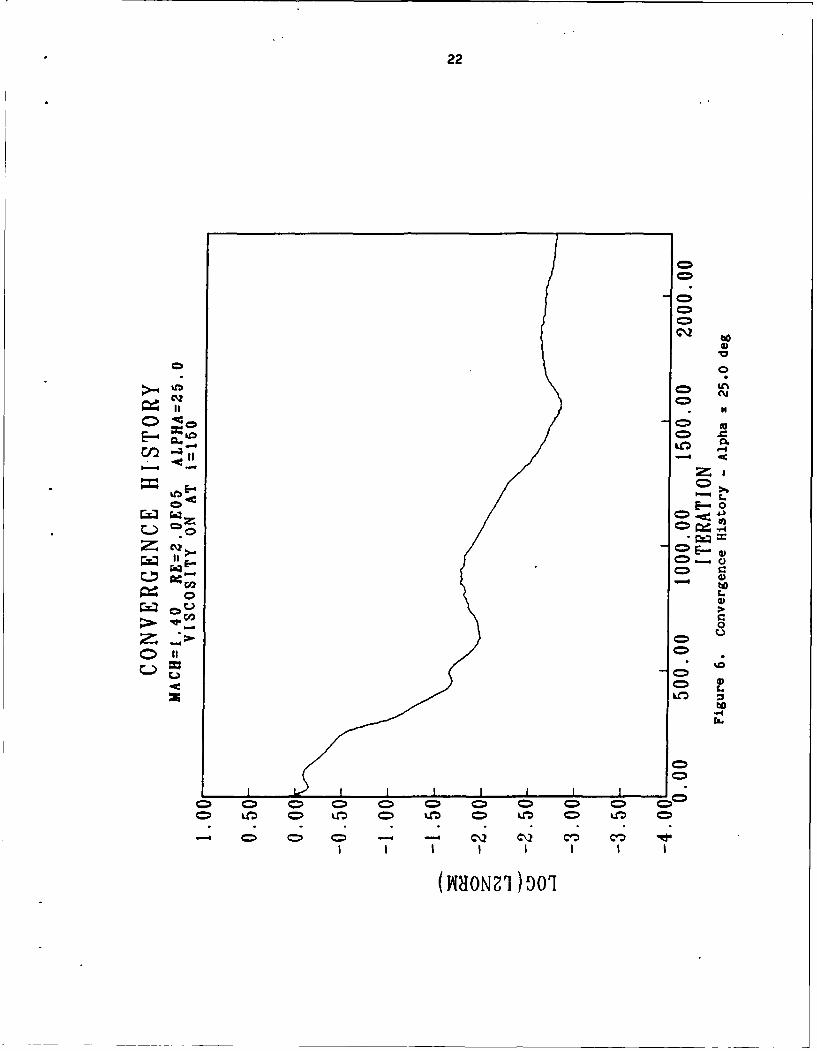
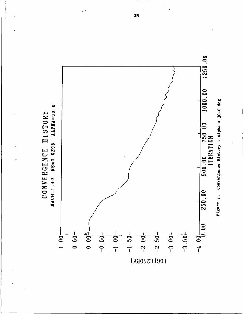
4.2 Convergence History
Due to the slow rate of convergence typical of viscous
solution algorithms, it was practlca to oain solutions
converged to machine zero. The L2 norm of the residual were
redced between three and four orders of magnitude for all
calculations. 7b insure that the flow structure was not
dependent on the convergence level, contours of flow variables
were cxmtpared to insure that no visible change had occured in the
last 500 iterations. Typical cone histories are show.. in
Figures 6 and 7. Figure 6 is a symetric vortex case at an angle
of attack of 25 degrees, and Figure 7 shows the convergence
history for a 30 degree angle of attack case, which is an
asymetric condition.
22
C20
C.o 4.
CO4
0
.4,
C)0
(WHONI)DO
23
C>2
- 0
0o
bo
0
Oilo
C\2' C*1C2
CHAFr~h( V
ANALYSIS
Flow solutions are presented for the five caliber tangent ogive
configuration at supersonic high angle of attack conditions. The Mach
number was 1.4 for all calculations and the angle of attack varied from
25 to 40 degrees. The Reynolds number was 200,000 based on body base
diameter. These flight conditions were chosen because of the wide range
of asymmetric vortical flaw patterns that arise. All calculations were
performed assuming laminar flaw so as to eliminate any effects a
turbulence model may have on the onset and development of asymmetry.
Based on Binion and Stanewsky2 9 , the assuption of laminar
flow at this Reynolds number and high angles of attack is a valid one.
In this analysis all streamlines were cxspited using PLC)T3D. 3 0
This program uses a 2nd order Runge-Kutta integration routine with five
integration steps per grid cell. The streamlines on all of the
two-dimensional cross-sections of the flow were calculated on a plane one
half cell foward of the last constant i grid plane since it is
perpendicular to the body longitudinal direction. Since the plane of
cell centers is not exactly perpendicular, the longitudinal nmentum
ccffponent was set to zero for plotting purposes. A non-zero momentum
term, while using PLOT3D, will give incorrect two-dimensional streamlines
if the grid is not perpendicular to the body. These streamline plots are
viewed from the upstream direction. Since these streamline calculations
involve only two of the three velocity components they are not24
25
necessarily projections of the three-dimensional streamlines onto the
cross-sectional plane. A particle injected into the flow at a specific
location will not neocessarily follow the streamlines given by the
two-dimensional calculations. During the analysis, sufficient
three-dimensional streamline calculations were performed to insure that
the two-dimensional calculations represent true three-dinensional
structures. For example, three-dimensional streamlines originating near
the nose were traced tb the end of the body to insure that the vortex
centers are located in the spots indicated by the two-dimensional
calculations (Figure 8). Also, the points of attachment and separation as
given by the limiting streamlines were compared to the points of
attachment and separation suggested by the two-dimensional streamlines
(Figure 9).
Figure 10 shows the streamlines at 25 degress. The flow is symmetric
at this angle of attack. This two-dimensional streamline calculation is
on a cross-section one half cell forward of the back of the body. This
location is X/L=97.0%. The flow is dominated by two large, symmetric
vortices formed by the separation and roll up of the shear layer. Figures
11 and 12 show the left and right secondary flow regions, respectively.
Each secondary flow region contains three nodes, I saddle, and four half
saddle points. Figure 13 shows the crossflow topology for this case.
This is in agreement with equation (7), and thus is a kinematically possible
flow.
Figure 14 shows the vortical flow pattern at 30 degrees angle of
attack. In this case the flow is dominated by two large, slightly
asymmetric vortices. These primary vortices induce a cxmplicated
structure of secondary separations, attachments, and vortices. Figure 15
26
U,0C
-4-4SCu0L.
ci,
-4CuC0
-4U,C0S'-4
03
*0CCu
'-4CuC0
a,C0E
__________________________ -4
0______________ 0
_________________________ L
C.-0
C0a,
L.Cu0.a00
0)L.
t~o-4CL.
27
0
00
U)
'-40
0-.4
0
"-6
03
(U
0
-4'-4
00
LI)
C-I
-4
-.4
'40
C0W)
-4
U0
U
0%
0I..
-.4ra..
28
Ci
06
14
C
.14
29
cc
0
Ui
CM
to
30
CN
Cl)x
0
o0
31
Fiur 13 roslw oolg
Alh 250dg N/ 70
32
Figure 14. Streamlines AlPpha 30.0 deg, X/L 97.0%
33
LO
c/)
-4-
34
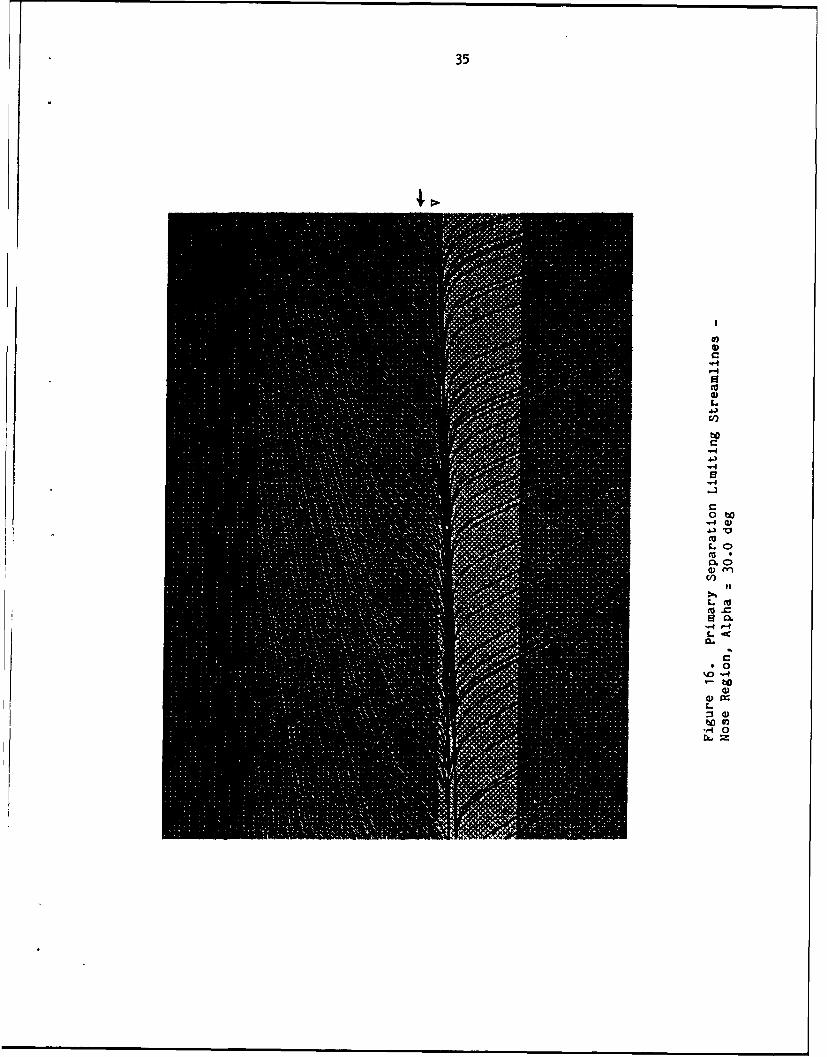
shows the limiting streamlines plotted on the back portion of the body.
The view shown is one in which the observer is at the rear of the body
looking down inside the body towards the nose. The first layer of grid
points is shown to give a sense of perspective. The blank region at the
stagnation point is the block to block cxnnection. There are 12 points of
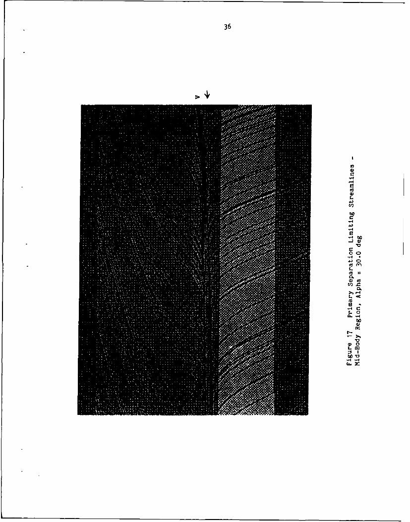
separation and attachment visible. The primary separation nodes at the
rear of the body look as if they each consist of two urm=ncted groups
of streamlines. These are connected near the nose as shown in Figure 16
but split apart about a third of the way down the body. They briefly
reconnect before splitting a second and final time (Figure 17). Several
places were observed where streamlines connect these two lines but these
were very few. It is not known whether this is a feature of the flow,
the effect of decreasing grid resolution near the rear of the body, or
the lack of a sufficient concentration of particle traces generated by
the plotting package. Grid resolution appears to be the least likely
since the two regions reconnect in a coarser region of the grid than
where they first separated. A two-dimensional streamline calculation in
a cross-sectional view of this region shows no unusual structure
associated with the primary separation line (Figure 18). All of the
separation and attachment lines start at the nose (Figure 19).
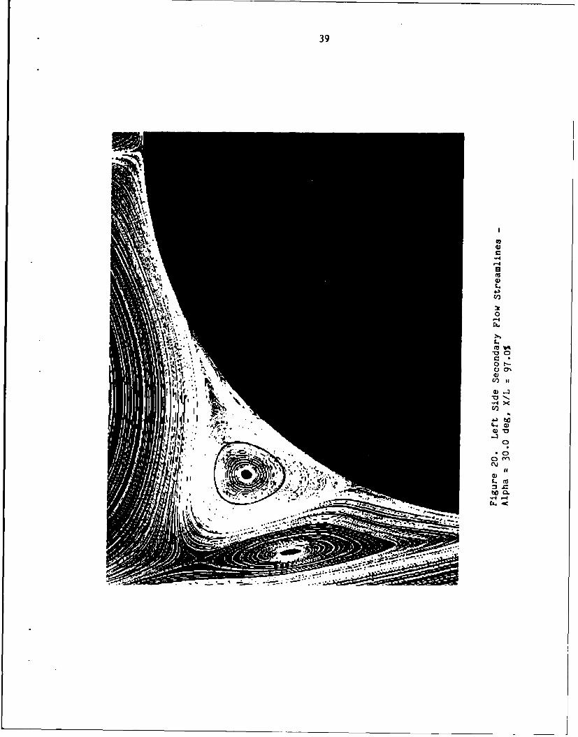
A detailed streamline calculation of the left secondary separation
region is shown in Figure 20. There are three nodes, one saddle, and
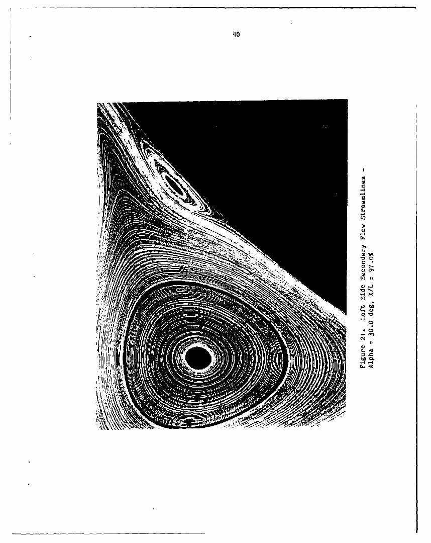
four half saddle points in this region. The two vortices closest to the
body (Figure 21) are associated with separation and reattachment half
saddle points, while the remaining vortex is associated with a full
saddle point and is separated from the other two vortices by streamlines
from the primary vortices. This vortex does not appear to be directly
35
b,
0 t
C
4
0-
to'U
36
U,0C
-4'-42'U0L
4~)C,,
C-4
-4S
~ 0
C00
-4 .
(U mL(U II
0(U("-C
L ~(U
~4CLa
w0
V00
~ IWV
"-4 -4Ci~Z
ol.
38
co)
LCL
)L
cf)1-
39
10 )0 l
-4X
C)
~40
400
0 l
a CCD
4-) OD
to
b3m
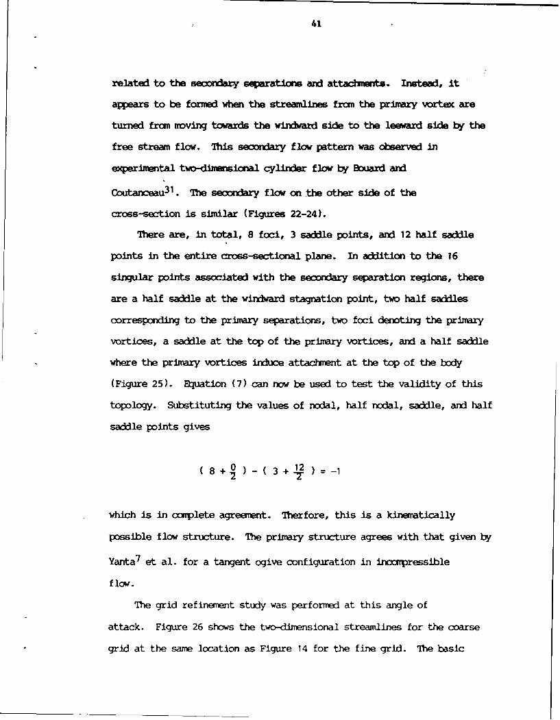
41
related to the secordary seaaratouw and attlmvs. Instead, it
appears to be formed when the streamlines from the primary vortex are
turned from moving towards the windward side to the leeward side by the
free stream flow. This seondary flow pattern was observed in
experimental two-di nsional cylinder flow by Bouard and
Coutanceau 3 1 . The secondary flow on the other side of the
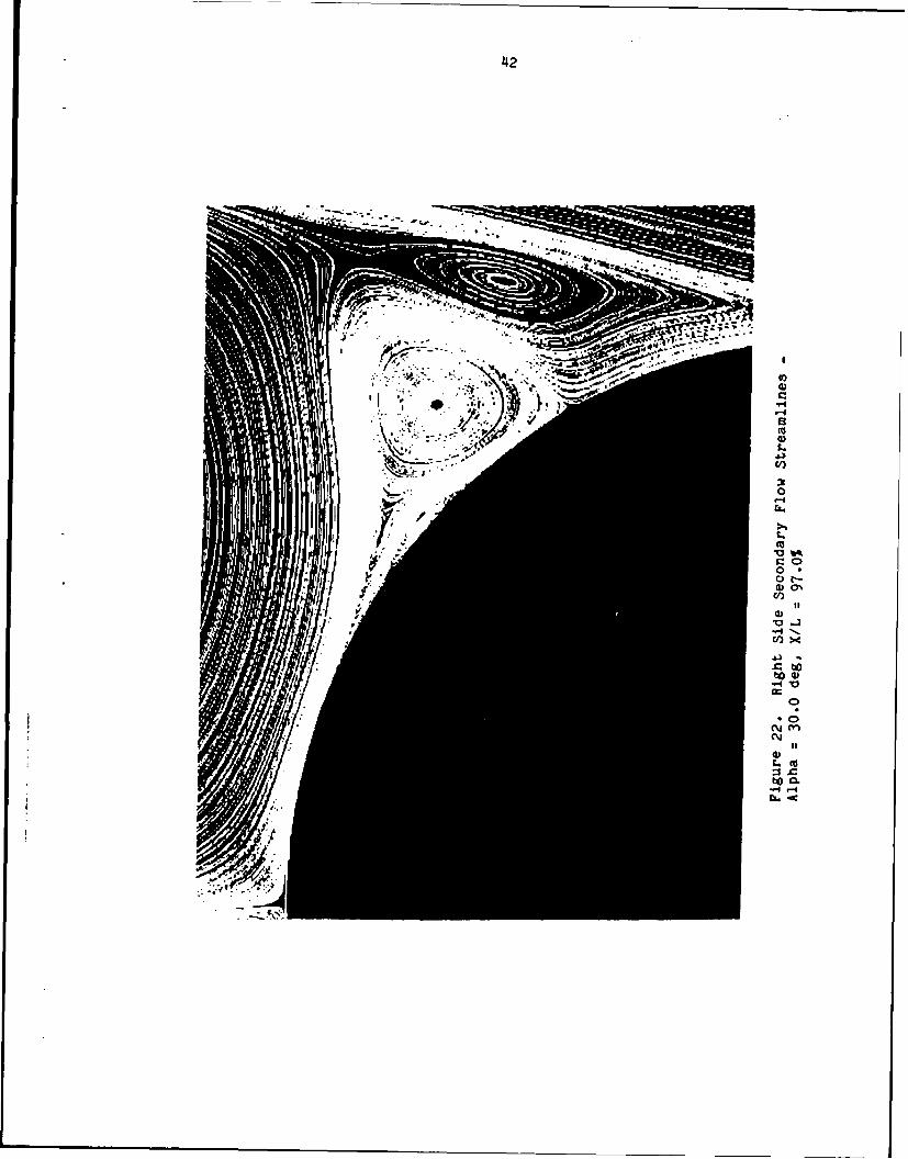
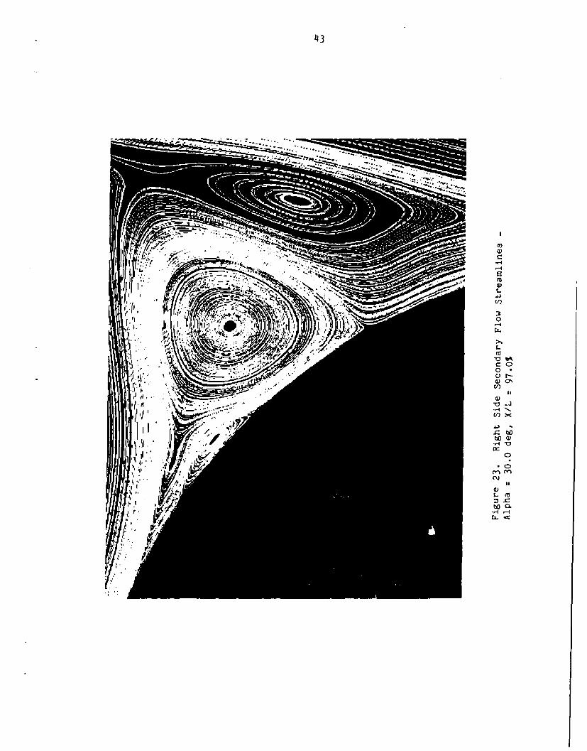
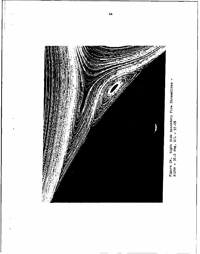
cross-section is similar (Figures 22-24).
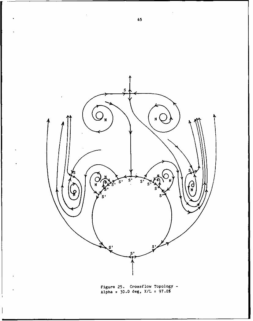
There are, in total, 8 foci, 3 saddle points, and 12 half saddle
points in the entire cross-sectional plane. In addition to the 16
singular points associated with the secordary separation regions, there
are a half saddle at the windward stagnation point, two half saddles
corresponding to the primary separations, two foci denoting the primary
vortices, a saddle at the top of the primary vortices, and a half saddle
where the primary vortices induce attachment at the top of the body
(Figure 25). Bquation (7) can now be used to test the validity of this
topology. Substituting the values of nodal, half nodal, saddle, and half
saddle points gives
8 + 0 3 + 12 =-12 2T
which is in complete agreement. Therfore, this is a kinematically
possible flow structure. The primary structure agrees with that given by
Yanta 7 et al. for a tangent ogive configuration in incompressible
flow.
The grid refinement study was performed at this angle of
attack. Figure 26 shows the two-dimensional streamlines for the coarse
grid at the same location as Figure 14 for the fine grid. The basic
42
400
'-D
-4to 4
V
'4
toz C
4I3
'40
C C>
JII
V)x
.14 V
oa)
44'
C
-40
Nli 4 Ci)
ti. 0.~ / '-4
45
Alph 30. d, s/L 9s.0
46
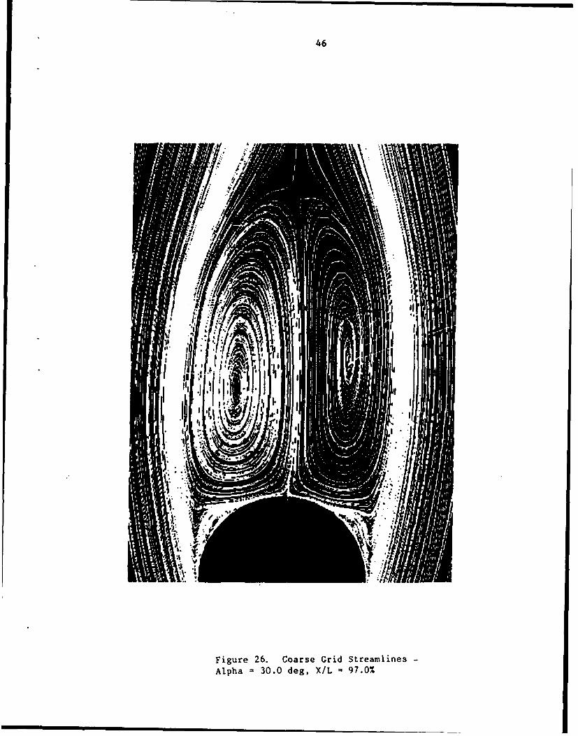
Figure 26. Coarse Grid Streamlines-
Alpha 30.0 deg, X/L =97.0%
47
structure of the primary vortices remained the same. The seondary flow
is not the same, but is similar. Much of the detail shown in Figures
20-24 is missing. This is to be expected since the grid resolution was
muxh lower in this region. This may indicate that if the dimensions of
the fine grid used was increased substantially, additional singular
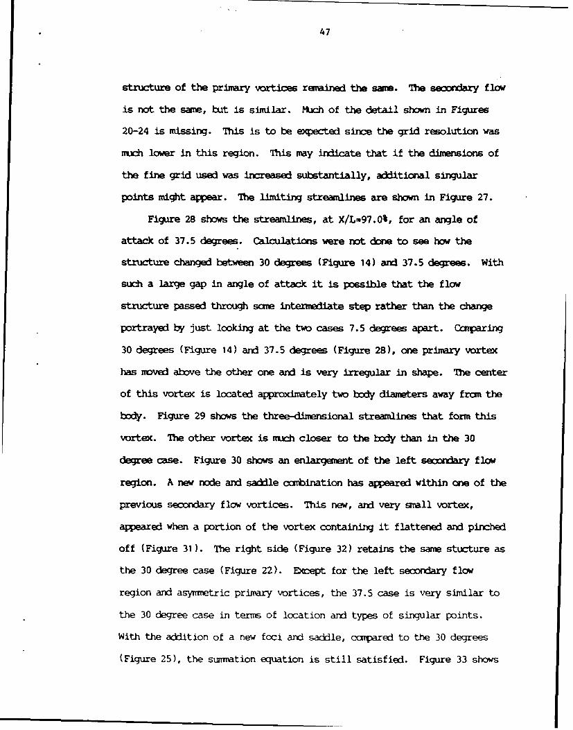
points might appear. The limiting streamlines are shown in Figure 27.
Figure 28 shows the streamlines, at X/L-97.0%, for an angle of
attack of 37.5 degrees. Calculations were not done to see how the
structure changed between 30 degrees (Figure 14) and 37.5 degrees. With
such a large gap in angle of attack it is possible that the flow
structure passed through some intermediate step rather than the change
portrayed by just looking at the two cases 7.5 degrees apart. CcFparing
30 degrees (Figure 14) and 37.5 degrees (Figure 28), one primary vortex
has moved above the other one and is very irregular in shape. The center
of this vortex is located approximately two body diameters away frca the
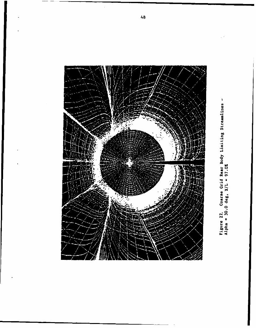
body. Figure 29 shows the three-dimensional streamlines that form this
vortex. The other vortex is much closer to the body than in the 30
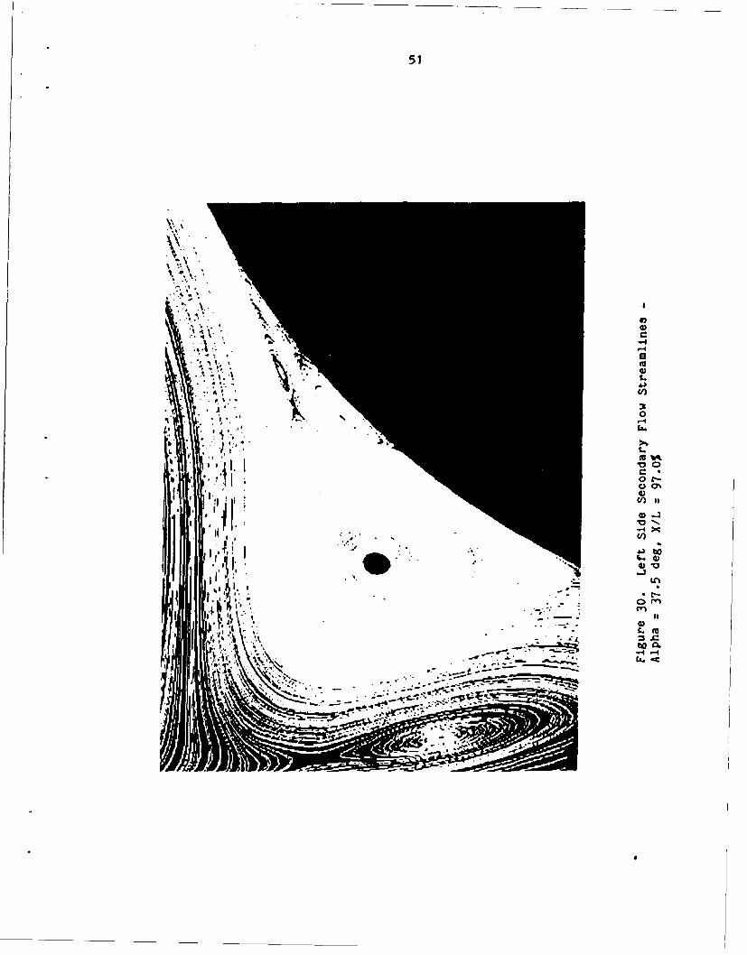
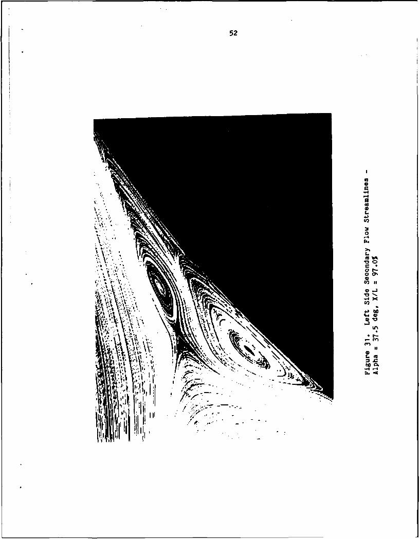
degree case. Figure 30 shows an enlargement of the left secondary flow
region. A new node and saddle combination has appeared within one of the
previous secondary flow vortices. This new, and very small vortex,
appeared when a portion of the vortex containing it flattened and pinched
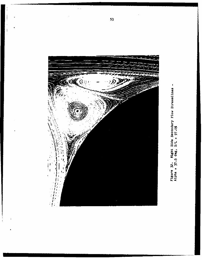
off (Figure 31). The right side (Figure 32) retains the same stucture as
the 30 degree case (Figure 22). Ewbept for the left secondary flow
region and asymmetric primary vortices, the 37.5 case is very similar to
the 30 degree case in term of location and types of singular points.
With the addition of a new foci and saddle, ccmpared to the 30 degrees
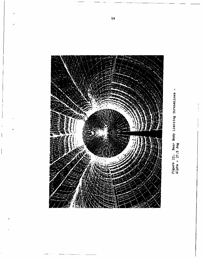
(Figure 25), the summation equation is still satisfied. Figure 33 shows
48
ad 0
C14
I-

49
Figure 28. Streamlines -Alpha 37.5 deg, XIL 97.0%
50
0 l-4 0
00
-. 44
-4.--
51
I,
D6
-.4%f
to4
UN
m)en
4.)
52
41.1
ol jI
53
wr - C
'U0S.4.)'a
3a-4C'
S.C
Vt'C 00*CJ t-* 0%'a
S.C0~)
-4-"'aN
a -'ceoto,.4v
U'
* I-.
enN
SS.Ctoo.
-4-
'4
I
54~
N 4
GO,
bC
ITG
55
the limiting streamlines on the back portion of the body for the 37.5
degree case. The overall pattern is the same as the 30 degree case
(Figure 15) although same skewness can be seen. The attachment node
resulting fran the primary vortices is offset to the left of the body
center line. The other nodes are slightly asymetric as well.
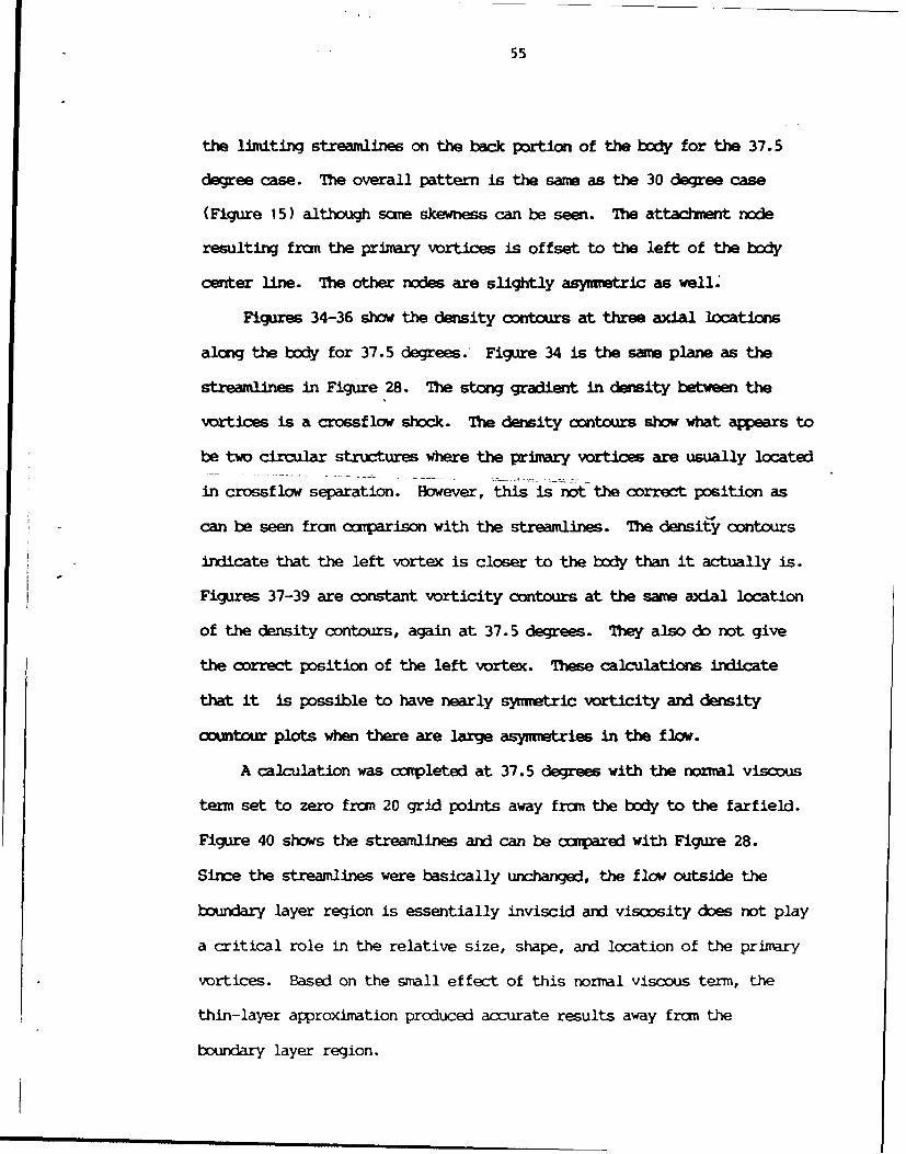
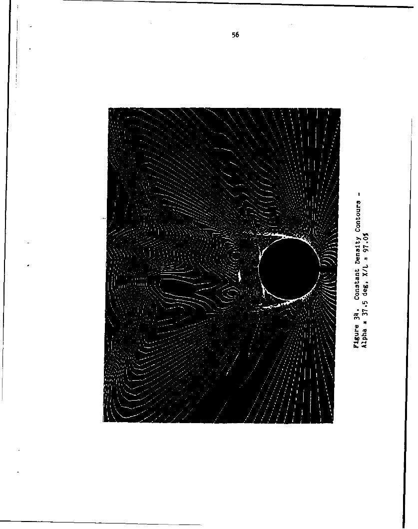
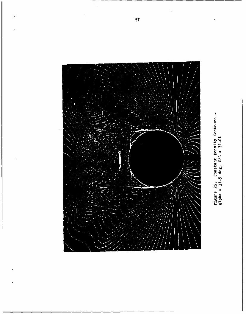
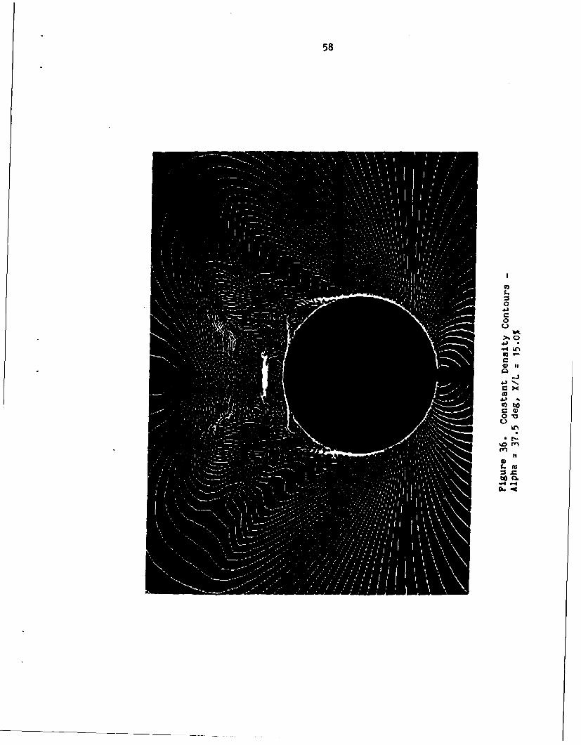
Figures 34-36 show the density contours at three axial locations
along the body for 37.5 degrees. Figure 34 is the samwe plane as the
streamlines in Figure 28. The stiong gradient in density between the
vortices is a crossflow shock. The density contours show what appears to
be two circular structures where the primary vortices are usually located
in crossflow separation. However, this is not the correct position as
can be seen from comparison with the streamlines. The density contours
indicate that the left vortex is closer to the body than it actually is.
Figures 37-39 are constant vorticity contours at the same axial location
of the density contours, again at 37.5 degrees. They also do not give
the correct position of the left vortex. These calculations indicate
that it is possible to have nearly symmetric vorticity and density
countour plots when there are large asymetries in the flow.
A calculation was comrpleted at 37.5 degrees with the normal viscous
term set to zero fram 20 grid points away from the body to the farfield.
Figure 40 shows the streamlines and can be compared with Figure 28.
Since the streamlines were basically unchanged, the flow outside the
boundary layer region is essentially inviscid and viscosity does not play
a critical role in the relative size, shape, and location of the primary
vortices. Based on the small effect of this normal viscous term, the
thin-layer approximation produced accurate results away from the
boundary layer region.
56
01LM
0
Gi
C
II
57
0
0
4--b. cf
58
U_
r.
ob'o
U) -
CL,
59
0~
0
-4C0
41
40
Lcto
4 -
4). -
60
0
0
to CL
")
61
04J
0
41
4)
o wg
0V
U%
a%'
to14'
62
Figure. 110 'treamli1ineis Al~pha 317. deg, X/L (17 .0
63
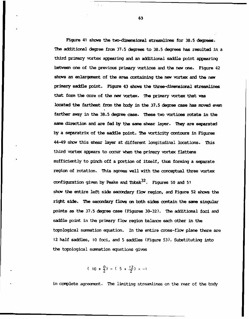
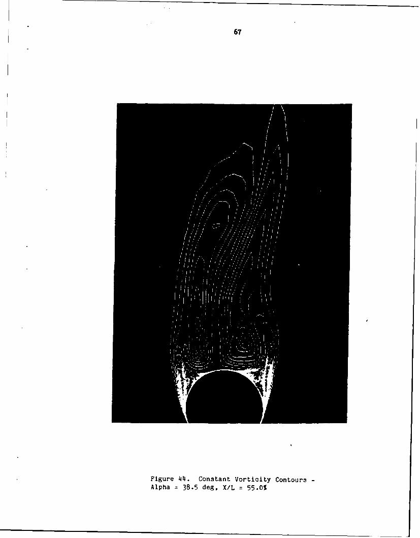
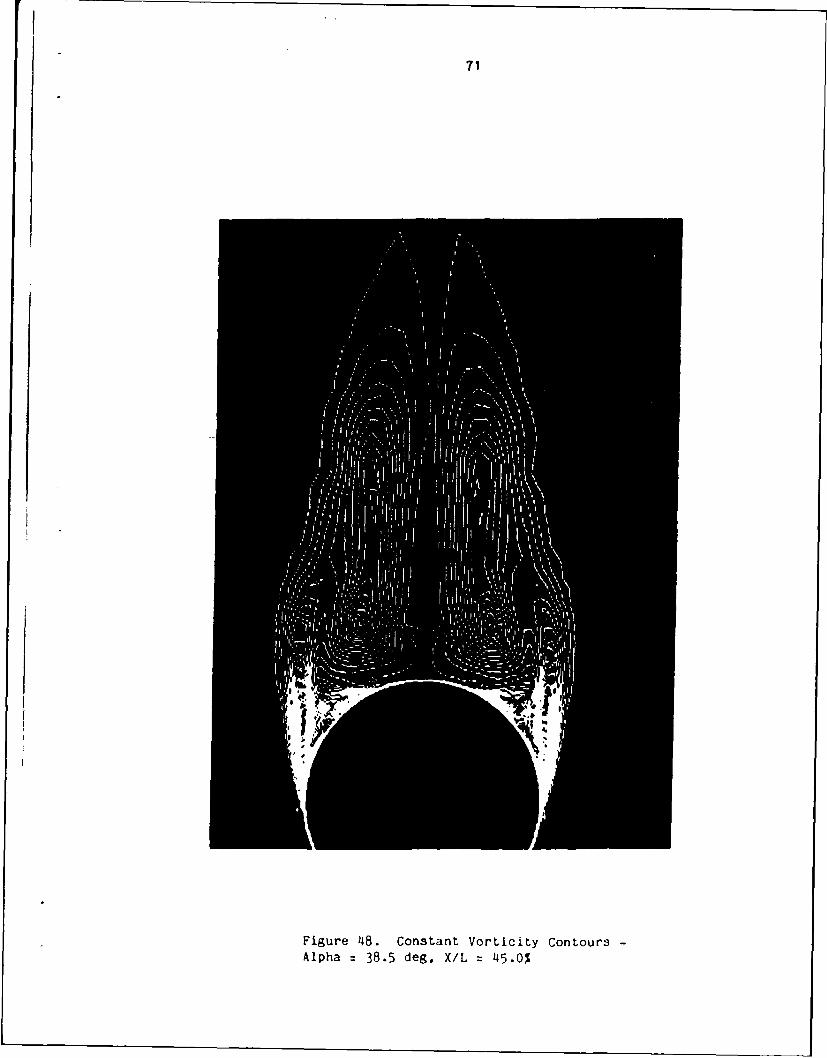
Figure 41 shows the tw-dimensional streamlines for 38.5 degrees.
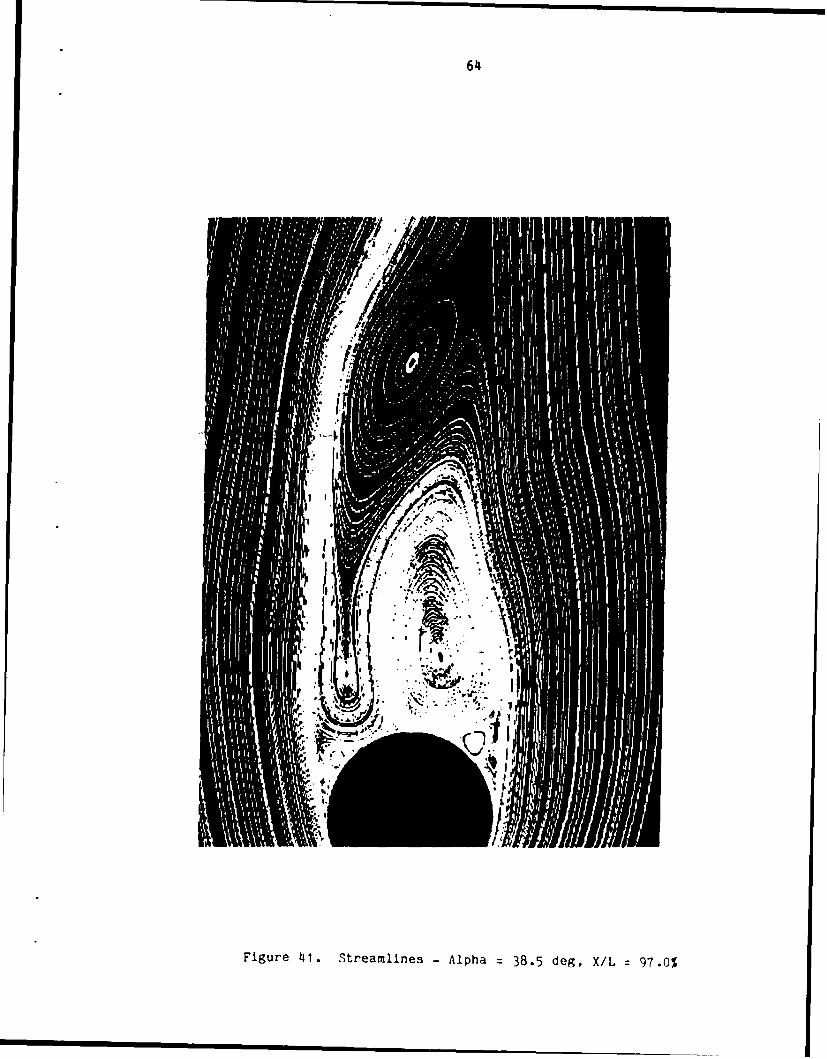
The additional degree fran 37. 5 degrees to 38.5 degrees has resulted in a
third primary vortex appearing and an additional saddle point appearing
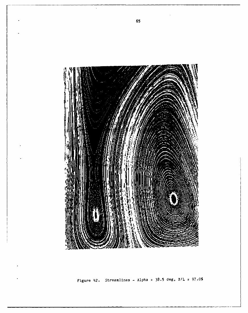
between one of the previous primary vortices and the new one. Figure 42
shows an enlargement of the area containing the new vortex and the new
primary saddle point. Figure 43 shows the three-dimensional streamlines
that form the core of the new vortex. The primary vortex that was
located the farthest fran the body in the 37.5 degree case has moved even
farther away in the 38.5 degree case. These two vortices rotate in the
same directicn and are fed by the same shear layer. They are separated
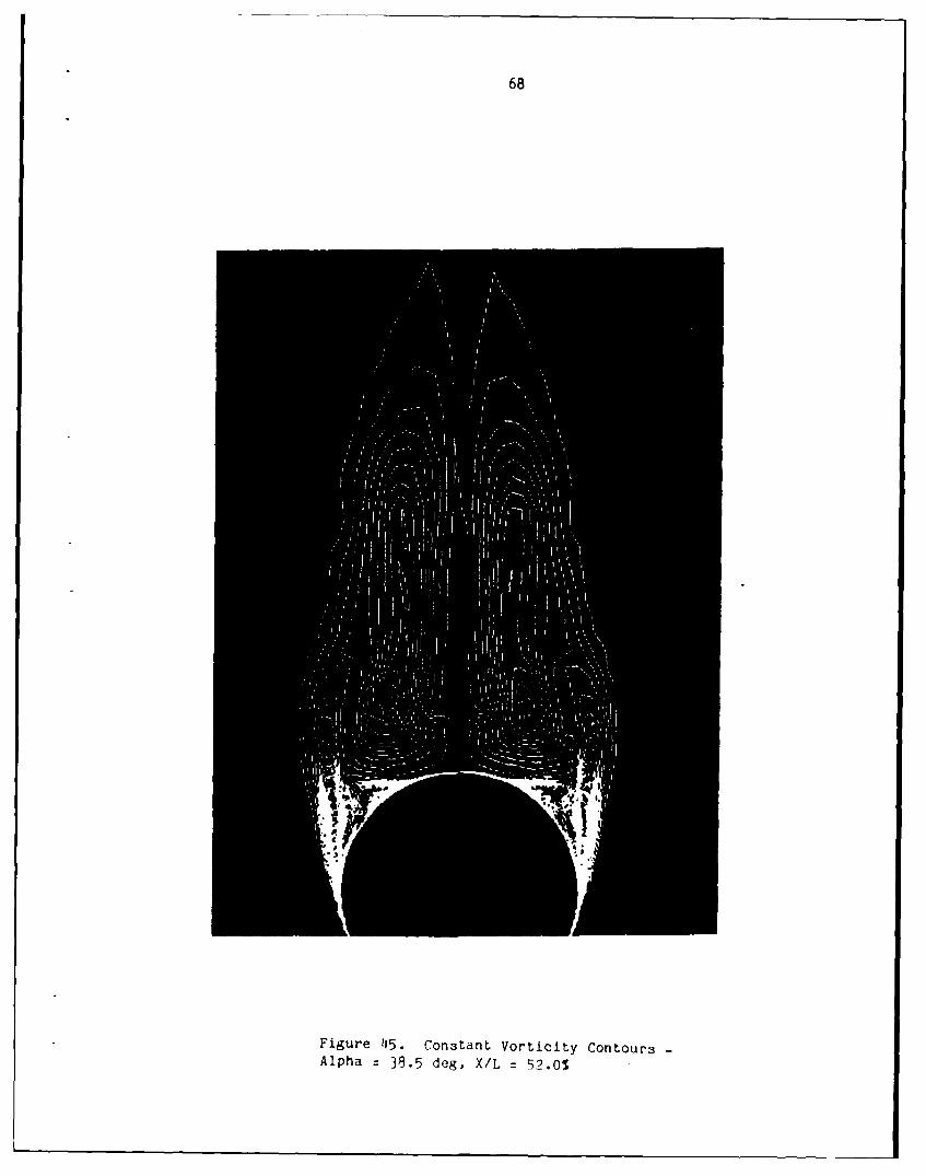
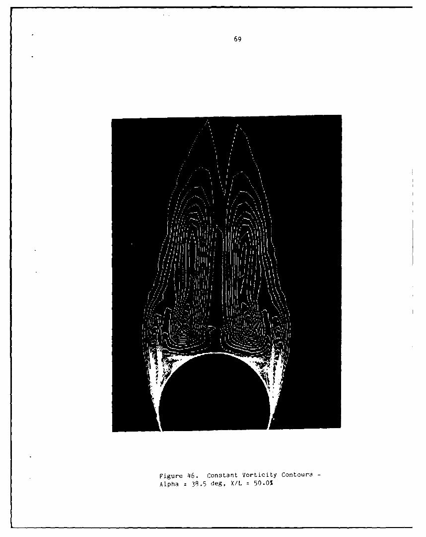
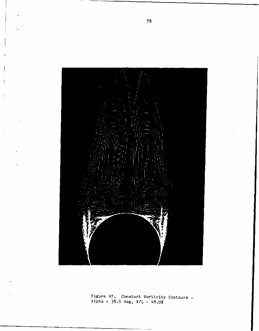
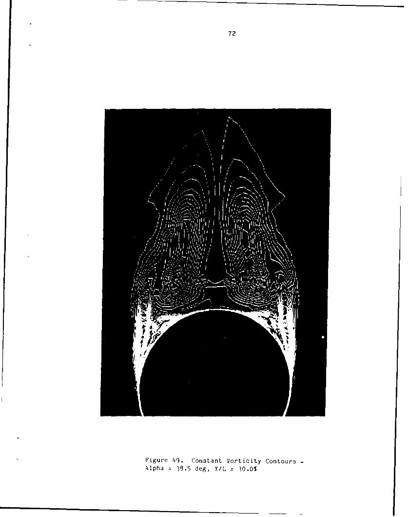
by a separatrix of the saddle point. The vorticity contours in Figures
44-49 show this shear layer at different longitudinal locations. This
third vortex apears to occur when the primary vortex flattens
sufficiently to pinch off a portion of itself, thus forming a separate
region of rotation. This agrees well with the conceptual three vortex
onfiguration given by Peake and Tabak 32 . Figures 50 and 51
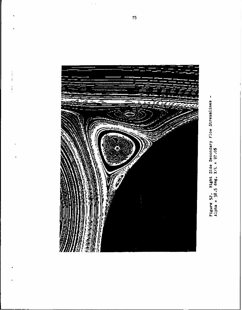
show the entire left side secordary flow region, and Figure 52 shows the
right side. The secondary flows on both sides contain the same singular
points as the 37.5 degree case (Figures 30-32). The additional foci and
saddle point in the primary flow region balance each other in the
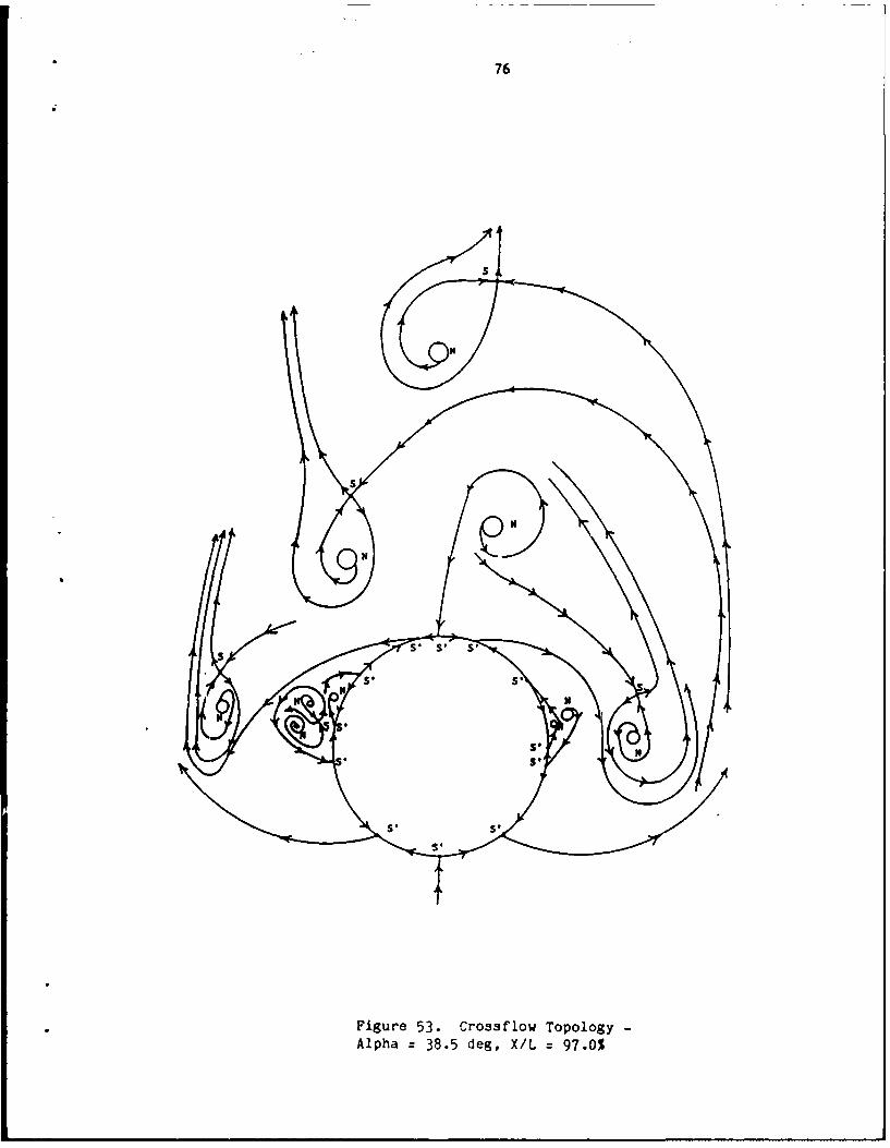
topological sumation equation. In the entire cross-flow plane there are
12 half saddles, 10 foci, and 5 saddles (Figure 53). Substituting into
the topological summation equations gives
10 + 0) - ( 5 + 12) = -
in complete agreement. The limiting streamlines on the rear of the body
64
Figure 4i1. Streamlines -Alpha =38.5 deg, X/L 97.0%
65
Figure 4~2. Streamlines -Alpha 38.5 deg, X/L 97.0%
66
ccC014
0h
U)
-4
67
Figure 44 Constant Vorticity Contours-Alpha 38.5 deg, X/L =55.0%
68
Figure 115. Constant Vortloity Contours-Alpha =38.5 deg, X/L=520
69
Figure 4~6. Cons~tanlt Vorticity Contours
Alpha =38.5 deg, X/L 250.0%
70
Figure 47. Constant Vorticity Contours-Alpha 38.5 deg, X/L =48.0%
71
Figure 48. Constant Vorticity Contours-Alpha 38.5 deg, X/L z 45.0%
72
Figure 4~9. Constant Vorticity ContoursAlpha 38.5 deg, X/L =30.0%
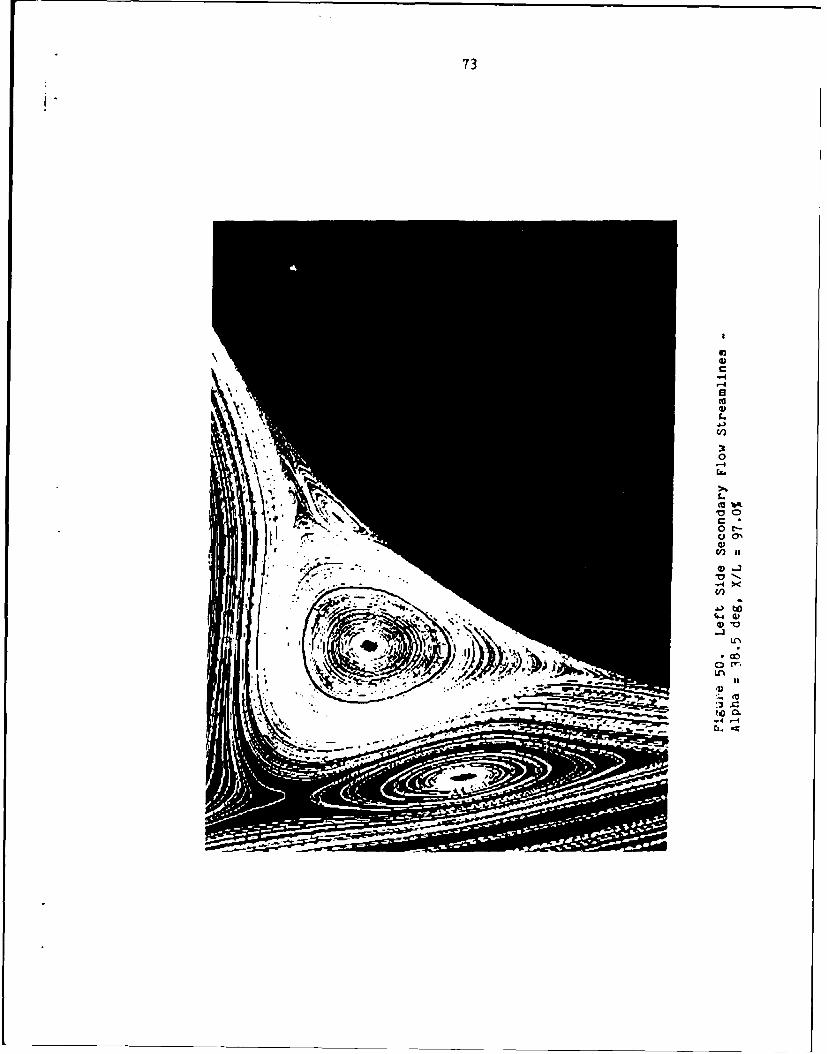
73
C)
0 t
0ni
.4maw
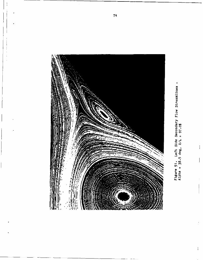
744
A-4
0 l0
-4 rqc-
75
cC/)
0
(D 0
to
0U'e
76
S. S .
Figure 53. Crossf'low Topology-Alpha 38.5 deg, X/L =97.0%
77
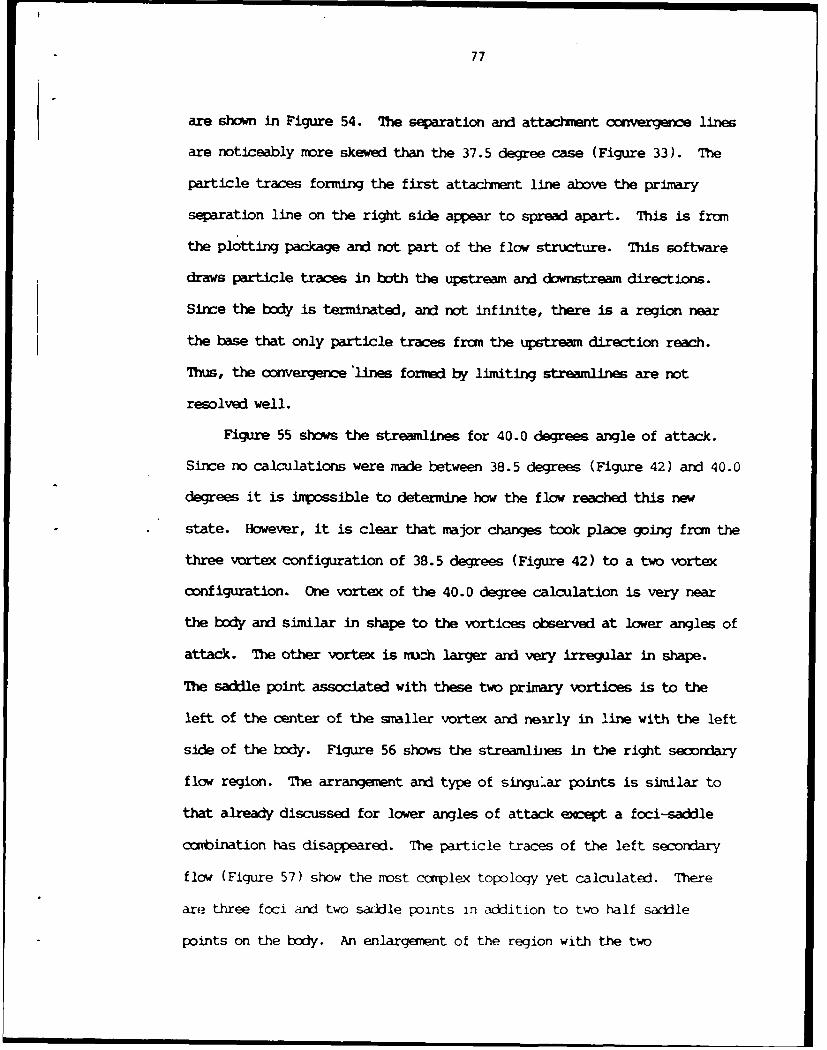
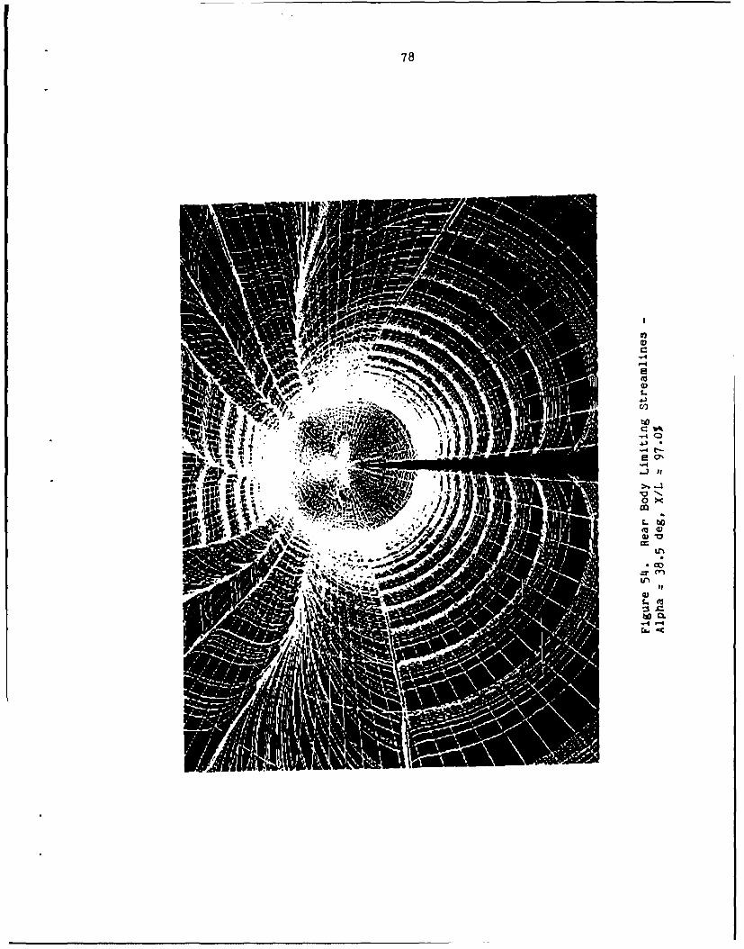
are shown in Figure 54. The separation and attachment e e lines
are noticeably more skewed than the 37.5 degree case (Figure 33). The
particle traces forming the first attachment line above the primary
separation line on the right side appear to spread apart. This is fran
the plotting package and not part of the flow structure. This software
draws particle traces in both the upstream and downstream directions.
Since the body is terminated, and not infinite, there is a region near
the base that only particle traces from the upstream direction reach.
Thus, the convergence 'lines formed by limiting streamlines are not
resolved well.
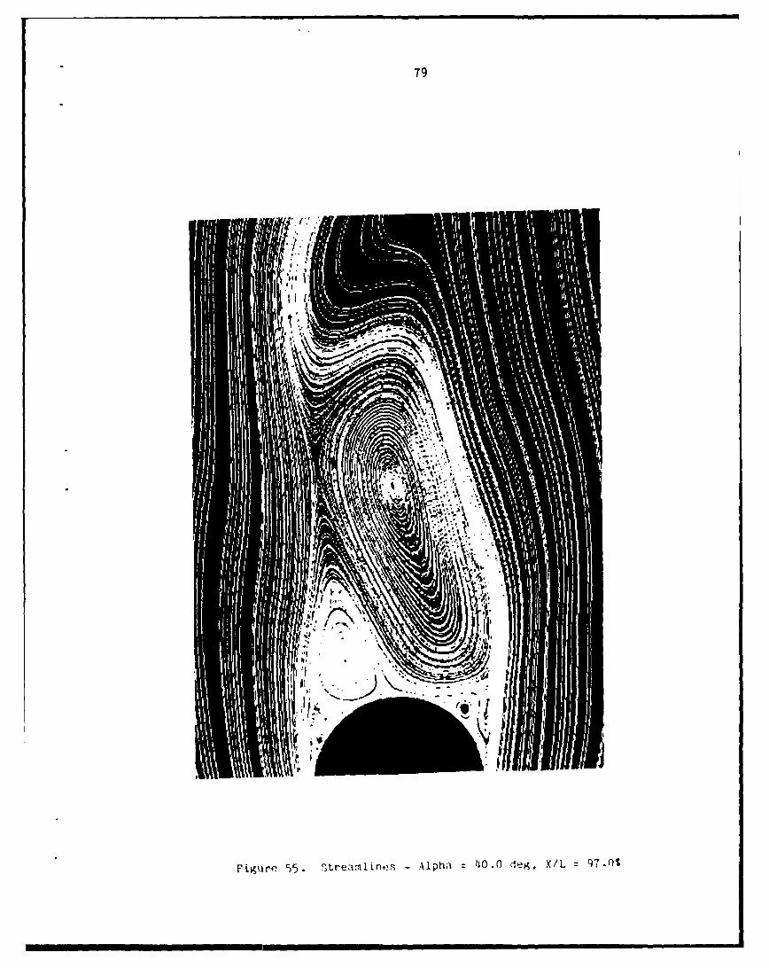
Figure 55 shows the streamlines for 40.0 degrees angle of attack.
Since no calculations were made between 38.5 degrees (Figure 42) and 40.0
degrees it is inpossible to determine how the flow reached this new
state. However, it is clear that major changes took place going from the
three vortex configuration of 38.5 degrees (Figure 42) to a two vortex
configuration. One vortex of the 40.0 degree calculation is very near
the body and similar in shape to the vortices observed at lower angles of
attack. The other vortex is mu--h larger and very irregular in shape.
The saddle point associated with these two primary vortices is to the
left of the center of the smaller vortex and nearly in line with the left
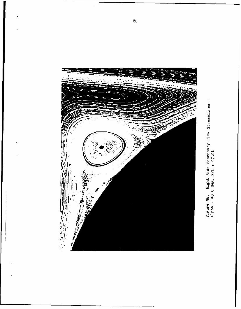
side of the body. Figure 56 shows the streamliies in the right secondary
flow region. The arrangement and type of singular points is similar to
that already discussed for lower angles of attack except a foci-saddle
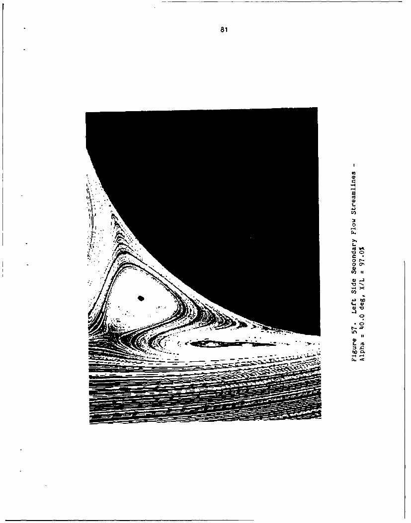
combination has disappeared. The particle traces of the left secondary
flow (Figure 57) show the most complex topology yet calculated. There
are three foci and two saddle points in addition to two half saddle
points on the body. An enlargement of the region with the two
78
100
C')a
C %
4) -
79
Figure 55. Otrezvnline3 - Alphi' 140.0 deg, X/L 970
80
c0
040
ti 0
In
o06
81
-4
a V
Cl)
41b 00
f-=
t.
CUb
C
pill-
82
foci-saddle point amtination is shown in Figure 58. This gives, in the
overall flow, eight nodes, three saddles, and 12 half saddle points.
Substituting into the topology summation equation gives
(7 +) - ( 2 +1). -1'2 -7
again in complete agreement. Figure 59 shows the limiting streamlines on
the rear of the body. They are highly asymmetric and contain a number of
sharp kinks.
Figures 60-64 show the circumferential coefficient of
pressure at X/L=97.0% for all the angles of attack calculated. Theta
equal to zero and 360 correspond to the windward stagnation point. The
direction of rotation is clockwise in relation to the two-dimnsional
streamline calculations previously shown. The symmetric pressure
coefficient distribution agrees qualitatively with Lamont 6 and Ericsson
and Reding3 3 . The bmps in the pressure coefficient at
aprroximtely a theta of 135 degrees for each of the cases correspond to
the portion of the secondary flow with the small vortices nearest the
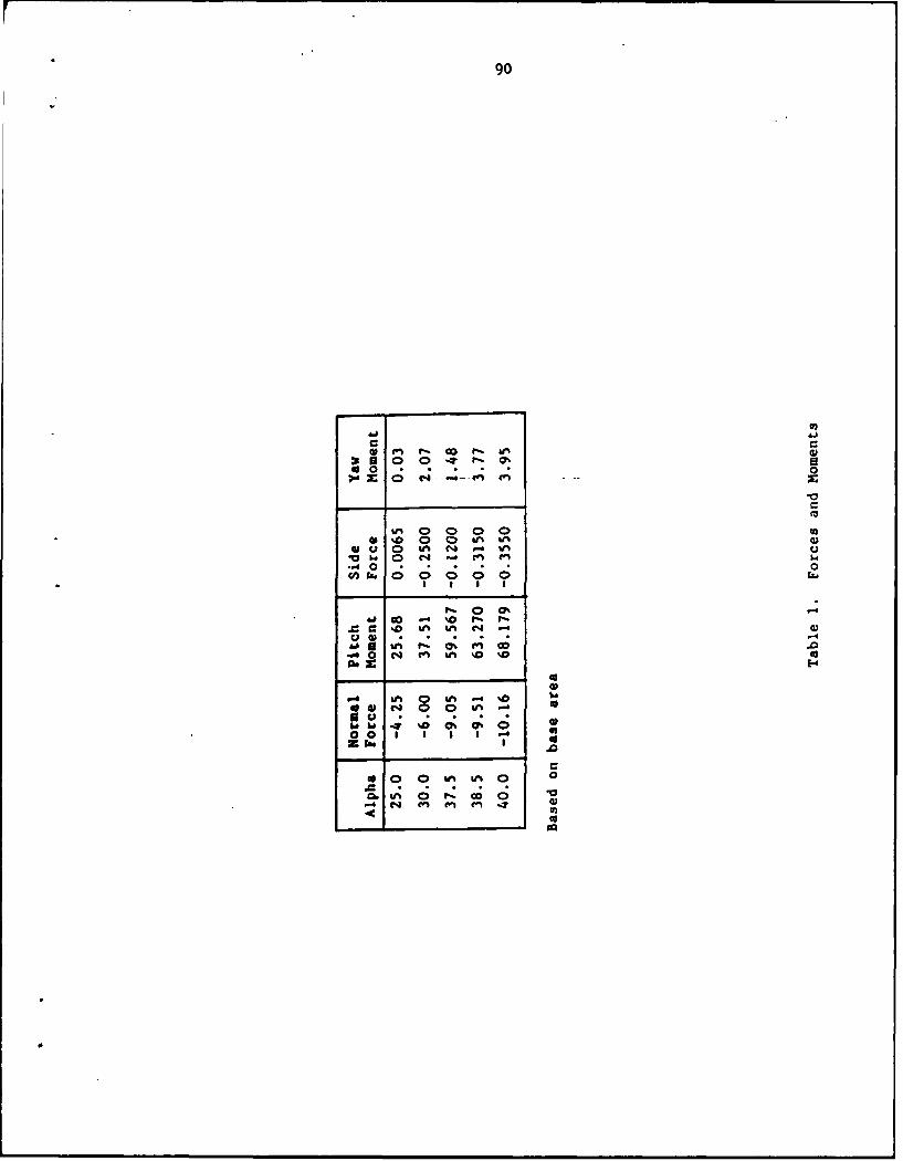
body. Table 1 gives the forces and moments for all cases calculated.
Since the free stream flow is supersonic the vortex-induced side forces
are smaller than the normal force, agreeing qualitatively with
Lamont 6 , Ericsson and Reciing34 , and Keener 9 et al.
83
-4. . . . . ... ...
84
E0,
L
-40-
9L t
85
cra)
I~- -4
C:))CQ C\Z
86
4r)
0 ./
et,,
C/a
all
to 0
- - .- 4 .-.. "" 4 O.4
. • ----+ S,- I
*1o" s II
/ -m
87
c -4
C44
4r
o to
C'? 4)
cl0 SIp
88
'0 0o4
C)
CD
CL.-
-3)
• ,4 C7%
0
III
60 10
-
89
-4
t 06
C..CV
90
00 0
0 0 1 ~4 V
0*
0. C0
4 '.4 In Inl fn .1 CU..................
CHAPER VI
CC1 CLUSIGNS
Asypmtric vortical flow has been calculated numerically using a
thin-layer Navier-Stokes algorithm. It was found that the thin-layer
aproximation models the physics acceptably in both the boundary-layer
and outer flow regions.
Both symmetric and asymnetric cases were calculated and analyzed.
The secondary flow was shown in detail. The basic structure was found to
agree qualitatively with experimental results, and a number of additional
structures and characteristics were observed. The complexity of the
secondary flow region increased with angle of attack.
Crossf low topology diagrams were given for symmetric and asymmetric
conditions to illustrate the fundamental difference between these
conditions. Asymmetry, according to this research, was characterized by
the change in the topological structure near the saddle point associated
with the primary vortices. In addition, the creation of a vortex by the
pinching of another vortex was found to occur. A saddle point was formed
in the middle of this two vortex structure. This phenomenon was observed
in both the primary and secdary flow.
In general, these results were in qualitative agreement with
experimental data, but showed additional structures not observed
previously.
91
RF CES
I. Keener, E.R., and Taleghani, J., "Wind Tunnel Investigations ofthe Aerodynamic Characteristics of Five Forexody Models at High Angles ofAttack at Mach Numbers from 0.25 to 2," National Aeronautics and SpaceAdministration Technical Mmoradum NASA TH X-73076, December 1975.
2. McElroy, G.E., and Sharp, P.S., "An Aproach to Stall/SpinDevelopment and Test,", American Institute of Aeronautics and AstronauticsPaper AIAA 71-772, July 1971.
3. Mounts, J.S., Belk, D.M., and Whitfield, D.L., "Program EAGLE -Users's Manual Volume IV: Multi-block, Implicit, Steady-State EulerAlgorithn," Air Force Armament Laboratory Technical Report AFATL-88-117,September 1988.
4. Chapman, G.T., 'Nonlinear Problems in Flight Dynamics," NationalAeronautics and Space Adinistration Technical Memrandum NASA-TM-85940,May 1984.
5. Legendre, R., 'Separation de 1'Ecoulement LaminaireTridimensional," La Recherche Aeronautique, No. 54, pp. 3-8, November-Deomter 1956.
6. Lamont, P.J., "Pressure Measur~nents on an Ogive Cylinder at HighAngles of Attack with Laminar, Transitional, or Turbulent Separation,"American Institute of Aeronautics and Astronautics Paper AIM 80-1556,1980.
7. Yanta, W.J., Wardlaw, A.B., and Sternklar, D., "Vortex AsymmetryDevelopment on a Tanget Ogive," Naval Surface Weapons Center TechnicalReport NSWC 82-394, October 1982.
8. Keener, E.R., "Flow-Separation Patterns on SymmetricForebodies," National Aeronautics and Space Administration TechnicalMauorancbkn NASA T-86016, January 1986.
9. Keener, E.R., Chapman, G.T., and Kruse, R.L., "Effects of MachNu ber and Afterbcdy Length on Aerodynamic Side Forces at Zero Sideslipon Symmetric Bodies at High Angles of Attack," American Institute ofAeronautics and Astronautics Paper AIAA 76-66, January 1976.
10. Keener, E.R., and Chapman G.T., "Onset of Aerodynamic SideForces at Zero Sideslip on Symmetric Forebodies at High Angles ofAttack," American Institute of Aeronautics and Astronautics Paper AIAA74-770, August 1974.
92
93
11. Peake, D.J., Owen, F.K., and Johnson, D.A., "Control of ForexxlyVortex Orientation to Alleviate Side Forces," American Institute ofAeronautics and Astronautics Paper AIAA 80-0183, January 1980.
12. Fidler, J.E., "Active Control of Asymmetric Vortex Effects,"American Institute of Aeronautics and Astronautics Journal of Aircraft,Volume 18, pp. 267-272, April 1981.
13. Ying, S.X., Schiff, L.B., and Steger, J.L., "A Numerical Studyof Three-Dimnsional Separated Flow Past a Hemisphere Cylinder," AericanInstitute of Aeronautics and Astronautics Paper AIAA 87-1207, June 1987.
14. Siclari, M.J., and Marconi, F., "The Ccmputation of Navier-Stokes Solutions Exhibiting Asymnetric Vortices," American Institute ofAeronautics and Astronautics Paper AIAA 89-1817, June 1989.
15. Whitfield, D.L., "Implicit Upwind Finite Volume Scheme for theThree-Dimensional Duler Epuations," Mississippi State University Report,Mr -ES-ASE-85-1, Sepetrber 1985.
16. Belk, D.M. and Whitfield, D.L., "Tize-Accurate Euler BquationsSolutions on Dynamic Blocked Grids," American Institute of Aeronauticsand Astronautics Paper AIM 87-1127, June 1987.
17. Gatlin, B. and Whitfield, D.L., "An Implicit, Upwind, Finite-Volume Method for Solving The Three-Dimensional Thin-Layer Navier-StokesBEuations," American Institute of Aeronautics and Astronautics PaperAIAA-87-1149, June 1987.
18. Simpson, L.B., "Unsteady Three-Dimensional Thin-Layer Navier-Stokes Solutions on Dynamic Blocked Grids," Ph.D. Dissertation,Mississippi State University, December 1988.
19. Roe, P.L., "AppraKidzate Riemann Solvers, Parameter Vector, andDifference Schemes," Journal of Ccmputational Physics, Volume 43, pp.357-372, 1981.
20. Davey, A., "Boundary-Layer Flow at a Saddle Point ofAttachment," Journal of Fluid Mechanics, Volume 10, pp. 593-610, 1961.
21. Lighthill, M.J., "Attachment and Separation in Three-Dimensional Flow," Laminar Boundary Layers, Section II 2.6, L. Rosenhead,ed., Oxford University Press, pp. 72-82, 1963.
22. Smith, J.H.B., "Remarks on the Structure of Conical Flow,"Royal Aircraft Establishment Technical Report RAE TR 69119, June 1969.
23. Perry, A.E., and Fairlie, B.D., "Critical Points in FlowPatterns," Advances in Geophysics, Volume 18B, pp. 299-315, 1974.
I a
94
24. Hunt, J.C.R., Abell, C.J., Peterka, J.A., and Woo, H.,"Kinematical Studies of the Flows Around Free or Surface-MountedObstacles; Applying Topology to Flow Visualization," Journal of FluidMechanics, Volume 86, Part 1, pp. 179-200, 1978.
25. Tobak, M. and Peake, D.J., "Tbpology of Three-DimensionalSeparated Fluid Flows," Annual Review of Fluid Mechanics, Volume 14, pp.61-85, 1982.
26. Sears, W.R., "The Boundary Layer of Yawed Cylinders," Journalof Aeronautical Sciences, Volume 15, Number 1, pp. 49-52, January 1948.
27. Legrdre, R., "Lignes de Courant d'un Etoulement Continu,"Rederche Aerospatiale., Number 105, pp. 3-9, 1965.
28. Thaqpon, J.F., "Program GLE - User's Manual, Volumes II andIII," Air Force Armament Laboratory Technical Report AFATL-TR-88-117,Setmer 1988.
29. Binion, T.W., and Stanewsky, E., "Observed Reynolds NurberEffects: Low Aspect Ratio Wings and Bodies," Advisory Group for AerospaceResearch and Development Conference Proceedings AGARD CP-232, 1989.
30. Walatka, P.P. and Buning, P.G., "PLOT3D User's Manual," NationalAeronautics and Space Administration Technical Memorandum NASA TM-101067,1989.
31. Bouard, R., and Coutanceau, M., 'Mhe Early Stage of Developrentof the Wake Behind an Impulsively Started Cylinder for 40<RE<10,000,"Journal of Fluid Mechanics, Volume 101, Part 3, pp. 583-607, 1980.
32. Peake, D.J., and Tobak, M., "On Issues Concerning FlowSeparation and Vortical Flows in Three Dimensions," Advisory Group forAerospace Research and Dvelopmnt Conference roceedin AGRD CP-342,April 1983.
33. Ericsson, L.E., and Reding, J.P., "Asymmetric Vortex SheddingFran Bodies of Revolution," Progress in Aeronautics and AstronauticsVolume 104, 'Tactical Missile Aerodynamics," American Institute ofAeronautics and Astronautics, 1986.
34. Ericsson, L.E., and Reding, J.P., "Vortex-Induced AsymmetricLoads in 2-D and 3-D Flows," American Institute of Aeronautics andAstronautics Paper AIAA 80-1269, 1980.