Ultra-long MicroStrip Gas Counter for Spallation Neutron Source Facilities
1
Report of the Fifth Spallation Neutron Source Accelerator Advisory Committee Meeting
SNS Accelerator Advisory Committee
July 10, 2013
Table of Contents 1 Executive Summary ............................................................................................................ 3 2 Findings, Comments and Recommendations ...................................................................... 4
2.1 Operational Priorities, Accelerator Performance .......................................................... 4
2.1.1 Findings and Comments ....................................................................................... 4 2.1.2 Recommendations ................................................................................................ 6
2.2 Ion Source and RFQ .................................................................................................... 6
2.2.1 Ion Source ............................................................................................................ 6 2.2.2 RFQ ...................................................................................................................... 7 2.2.3 Integrated Test Stand ........................................................................................... 8
2.3 Front End and Normal-Conducting (NC) Linac ............................................................. 9
2.3.1 Findings ................................................................................................................ 9 2.3.2 Comments ...........................................................................................................10 2.3.3 Recommendation .................................................................................................10
2.4 Superconducting Linac Performance ..........................................................................10
2.4.1 Findings and Comments: .....................................................................................10 2.4.2 Recommendations ...............................................................................................11
2.5 High Voltage Converter Modulators ............................................................................11
2.5.1 Findings and Comments ......................................................................................11 2.5.2 Recommendations ...............................................................................................12
2.6 RF and Electrical Systems ..........................................................................................13
2.6.1 Findings and Comments: .....................................................................................13 2.6.2 Recommendations ...............................................................................................13
2.7 Superconducting Linac Cryomodules and Cryogenics ................................................13
2.7.1 Findings and Comments ......................................................................................13 2.7.2 Recommendations ...............................................................................................14
2.8 HEBT/Ring/RTBT, Foil Development, Laser Wires and Laser Stripping ......................14
2.8.1 Findings and Comments ......................................................................................14 2.8.2 Recommendations ...............................................................................................15
2.9 Ring Beam Dynamics .................................................................................................15
2.9.1 Findings and Comments ......................................................................................15 2.9.2 Recommendations ...............................................................................................16
2.10 Target Systems ...........................................................................................................16

2
2.10.1 Findings ...............................................................................................................16 2.10.2 Comments ...........................................................................................................17 2.10.3 Recommendations ...............................................................................................18
2.11 Control Systems .........................................................................................................18
2.11.1 Findings ...............................................................................................................18 2.11.2 Comments ...........................................................................................................19 2.11.3 Recommendations ...............................................................................................19
2.12 Beam Instrumentation Systems ..................................................................................20
2.12.1 Findings ...............................................................................................................20 2.12.2 Comments ...........................................................................................................20 2.12.3 Recommendations: ..............................................................................................20
2.13 The 1.4 MW Upgrade Plan ..........................................................................................20
2.13.1 Findings and Comments ......................................................................................20 2.13.2 Recommendations ...............................................................................................21
2.14 Power Upgrade Project and Second Target Station ....................................................22
2.14.1 Findings ...............................................................................................................22 2.14.2 Comments ...........................................................................................................22 2.14.3 Recommendation .................................................................................................22
3 Responses to the Charge ..................................................................................................22
3.1 Charge 1 .....................................................................................................................22 3.2 Charge 2 .....................................................................................................................23 3.3 Charge 3 .....................................................................................................................24 3.4 Charge 4 .....................................................................................................................25 3.5 Charge 5 .....................................................................................................................25
4 Conclusion .........................................................................................................................26 5 SNS Accelerator Advisory Committee Charter ...................................................................26 6 Committee Membership .....................................................................................................28 7 Agenda for the Fifth Meeting ..............................................................................................30

3
1 Executive Summary
The Fifth Meeting of the SNS Accelerator Advisory Committee was held on May 7-9, 2013. The committee membership is shown in Section 6. Three members have retired (Alex Chao, Roland Garoby and Rod Keller) and five new members have joined (James Alessi, David Findlay, John Maclean, Eric Pitcher, and Martha Zumbro). At this meeting Gerry Dugan, Guenter Bauer and Andrew Hutton were unable to attend; Arne Freyberger stood in for Andrew Hutton.
The committee wishes to thank the SNS staff for their hospitality, well-prepared talks and helpful answers to our questions.
Several incidents and issues drove the meeting discussions. These include: several recent target failures, challenges associated with achieving higher power (1.4 MW) over the next few years, recent developments related to the Second Target Station and the associated power upgrade, and the desire on the part of the Research Accelerator Division management to hear suggestions for optimizing operational efficiencies. Accordingly, the committee heard several talks in plenary sessions on the first day, and then split into three breakout sessions on the second day. We were also given a tour of the facility. The agenda is included in Section 7.
The charge given to the committee was:
1. Assess the performance of the accelerator complex and neutron source to date. 2. Assess and provide advice on the plans for sustaining beam availability at the ≥90%
level at ~1MW beam power for 5000 operating hours per year in a constrained funding environment. In particular, assess at a high level the staffing and budget allocations for operating groups, spares inventory and management, and maintenance strategy.
3. Assess and provide advice on the plans, risks and associated mitigating activities for continuing the ramp-up in power of the accelerator complex and neutron source to the design level of 1.4 MW absent the Power Upgrade Project. Is the approach on the most critical systems (modulators, foils, SCL, target) appropriately directed?
4. Provide advice on the conceptual path toward 3MW operation and a Second Target Station.
5. Assess the response to the two unexpected target failures experienced in the fall of 2012, and plans for future target design and procurement.
Our responses to the charge are in Section 3.
The SNS accelerator complex is unique in many ways. It is the highest power pulsed neutron source, and is driven by the highest energy hadron superconducting linac, in the world. The SNS accumulator is the highest current ring. The liquid mercury target is a new technology now being pursued by others, but in which SNS has been in a leadership role. All of these factors suggest that the SNS accelerator is an outstanding place for challenging advances in accelerator science and technology. However, the committee recognizes that the SNS is primarily a production facility of pulsed neutrons for neutron science. The tension between supporting and producing science from the SNS beamlines and instruments on the one hand
4
and further developing the accelerator and target systems on the other hand lies behind most of the issues discussed at this meeting. This tension is manifest in at least three ways:
• Resources: at a high level, decisions must be made to provide resources to instruments and neutron science needs versus accelerator developments.
• Scheduling of User Beam Time: In order to advance accelerator developments, certain priorities must be given to scheduling issues. These choices will impact the facility users.
• Machine parameters: To provide the high reliability that facility users expect, it may be advantageous in the short term to run conservatively. However, the broad user community expects higher power operation in the future, and the path to ultimately realizing these improvements cannot be developed while running in this mode.
The majority of our comments and recommendations deal with these tensions and attempt to suggest a solution that is optimal for the facility as a whole. An observation noted independently in the breakout sessions, and thus a recurring theme in our recommendations, is that there are likely gains to be had by enhancing the dialog between the accelerator staff and the user community. We encourage SNS management to explore additional venues for this dialog in order to ensure that the needs of accelerator development are made known throughout the user community, while at the same time gathering feedback from the community on the impacts of the decisions.
2 Findings, Comments and Recommendations
The body of the report is broken into sections that follow both the outline from previous meetings (for sake of continuity) and additional sections that address specific newly introduced information at this meeting.
2.1 Operational Priorities, Accelerator Performance
2.1.1 Findings and Comments
As far as SNS operations are concerned, it is clear that the last few months have been dominated by the interruptions caused by the failure of two high-power neutron-producing targets in quick succession, and of course these failures have had an unfortunate effect on availability. But it is very important to note that consistent achievement of an availability of >90% for a pulsed accelerator at beam powers of ~1 MW is an excellent achievement by any standards — something for which SNS must be thoroughly congratulated.
As regards the target failures, one drawback about leading the world in spallation neutron source target technology is inevitably that unexpected events can occur; the only way out of a problematic event is to solve the problem and to move on, and this is something that SNS staff have done very professionally. Further, as a result of solving the target problem, enhanced quality assurance arrangements have been put in place which should prevent similar occurrences in the future and which have already identified a weakness in one of the targets already manufactured.

5
Of course, the performance of large accelerator facilities depends very much on the surrounding management and organizational arrangements, and here some useful changes have been made — as regards the design function, the operations function, and the interactions between design and operation. Moves are afoot here to ensure that more details of existing equipment and plant are being captured, to promote more flexible working practices (especially for maintenance-type tasks during shutdowns/outages), to encourage greater ownership of the “life cycle” of equipment from design through installation to operation and maintenance, and to try to make sure that deep and wide knowledge and experience accumulated since operations began are not lost at the end of people’s careers.
It can be tempting to let small changes march away with configuration management even though there is an effort in place to maintain and control changes for larger systems. Additional designer support is apparently needed to ensure that a number of smaller changes are captured in drawings. Similarly there is “tribal knowledge” that should be captured in checklists and procedures — for operational use as well as archival use.
Good progress has been made on developing transparent and inclusive processes for addressing overall priorities on SNS by gathering leaders for discussion and decisions, rather than leaving some decisions to be made at lower levels. Documentation of such top-level decisions is also an important tool in promoting such progress and for ensuring good communications.
To help prepare for the future, it may make sense to use formal project management tools, provided that the incorporation of excessive detail is avoided. Additionally, it is possible that greater use of formal project management techniques for planning outage activities could bring benefits.
It could make sense to develop more managed on-call arrangements for SNS. Whilst at present staff are highly motivated, have a high level of ownership, and respond well to call-in, the response to call-ins at present does seem to rely largely on the good will of staff. As original staff leave the project over time this may not continue to be the case1.
SNS may be vulnerable through not having timely access to transport casks for disposing of highly radioactive components (e.g. spent targets). The option of buying a suitably licensed cask and leasing it back to the waste transportation vendor was discussed; this may be worth following up.
It is clear that over the last year or two there has been a significant squeeze on funding for the accelerator and target, both for operations and development, but with a particular squeeze on funding for development. There appear to be several noticeable consequences of this:
• a shortfall in provision of spares — with some non-negligible operational consequences; • the gradual decay of suppliers’ skills for manufacturing specialized components
(because successions of orders to manufacturers are not being maintained); 1 More formalized arrangements involving rotations of staff should give the opportunity to cross-train staff. This may benefit the organization as a whole in spreading expertise.

6
• a lack of opportunity for accelerator and target R&D programs; and • a loss of morale amongst staff due to loss of R&D activities — which may eventually
become serious, as it is involvement in challenging and internationally recognized R&D programs that keep key staff at large accelerator-based facilities engaged in operations.
One technical operations area that seems to be particularly affected by the funding squeeze is the Vacuum Systems Team; here a lack of staff seem to be delaying operationally desirable programs — such as the replacement of ion pumps by turbo pumps on the drift tube linac. However, within the mechanical engineering functions there also seems to be a widely shared feeling that a lack of designers is their biggest staffing issue.
Overall we recognize the importance of delivering neutrons to users. This understanding is reflected the following recommendations.
2.1.2 Recommendations
1. Keep running within a cautious power régime until an adequate spare target inventory is successfully built up.
2. As regards scheduling cycle times for neutron users, it may become sensible to tailor schedules around natural time scales for targets, e.g. by arranging for operationally optimum times for changing targets to fall in the gaps between user cycles, and so:
3. Involve the user community (and the sponsor, DOE) in developing running schedules which are well matched to target lifetimes.
4. In the meantime there is considerable pressure from the sponsor to deliver routinely the design beam power of 1.4 MW to the target. However, in view of the overriding need to minimize loss of targets, the only practical way forward here is to take advantage of inevitably limited opportunities to extend pulse lengths and increase pulse currents at lower repetition rates, and so:
5. Use target-limited opportunities for beam tests to establish an optimum path towards 1.4 MW.
2.2 Ion Source and RFQ
2.2.1 Ion Source
2.2.1.1 Findings
The Committee heard from the Head of the Research Accelerator Division that the problems with source intensity decay over time is understood and remedied, antenna infant mortality is under control, and they now have three ion sources that can support routine operation. Steps taken in the process of resolving source contamination issues included setup and use of a clean room for assembly, standardization of procedures for source cleaning and assembly, and discovery and correction of a bad diaphragm pump on the vacuum storage vessel for spare sources which was contributing to contamination. Antenna failures have been reduced by very careful QA on antennas selected for use on the production sources. Issues of variability in the performance between sources is being addressed and reduced by careful comparison of

7
mechanical details of the 5 sources, measurement and matching of magnetic field profiles in the sources, and detailed comparisons of converter electrodes.
The ion source had a total of 57.7 hours of downtime for FY12 plus the first half of FY13. Using the LEBT chopper to deflect all beam onto the chopper target has proved to be very useful measure of the RFQ input current (which cannot be measured in any other way). This is becoming routine as a way to monitor source vs. RFQ performance.
The ion source current should be sufficient for 1.4MW operation, once the RFQ transmission is restored to previous levels by retuning.
2.2.1.2 Comments
The Committee was very pleased to hear that several problems that were concerns at the time of the previous review are now understood and resolved. The AAC recommended in the 2012 review: “In the short term we recommend focusing on the more limited program of thoroughly understanding the issues with the present sources.” This has been taken seriously by the source group, and there has been very good improvement in the performance of the ion sources. Three sources now predictably support 1MW operation for up to 6-week periods. They should be commended for these improvements in reliability and reproducibility, which have come from attention to details such as improved antenna QA, well defined procedures for source turn-on and conditioning, and better monitoring of LEBT electrode temperatures. These type improvements will continue to enhance performance. However, to ultimately achieve, in a robust way, reliable and stable H- intensity out of the linac, it is also desirable to increase the margin in current from the source over the requirements. To this end, the source group should be encouraged to resume source R&D, to test ideas they have for possible intensity and reliability improvements (external antenna studies to eliminate drop in source output over time, get internal antenna legs out of the plasma, try biasing the converter electrode, Cs collar improvements, etc.). The Integrated Test Stand will be heavily utilized for RFQ testing, LEBT and MEBT studies, so this source R&D needs to be a parallel effort in the ion source test stand. They should also investigate the possibility of antenna conditioning on a separate, more modest test bench that is independent from this ion source test stand.
2.2.1.3 Recommendations
6. Ion source R&D should resume in the source test stand, and this should then continue, separate and independent of the source required for the Integrated Test Stand.
2.2.2 RFQ
2.2.2.1 Findings
Since the last review, it was discovered that the RFQ transmission has dropped from ~90% to 75% at the same input current. They feel this reduction may have occurred as far back as 2011. This is the third instance of the RFQ detuning. In 2003 there was a frequency shift observed, possibly triggered by overheating of the cavity, and again in 2009 (possibly due to over pressurization of cooling lines). The suspicion is that a partial delamination of the bond

8
between copper and glidcop surfaces is occurring in the cavity. In this most recent instance, there has been no frequency shift, but rather a large change in the field profile is now measured along the RFQ. The plan is to retune the RFQ this summer. If transmission is restored, they should realize a gain of ~20% in current.
Delivery of a new RFQ is expected in July, 2013. In April, 2010 the vendor was selected, and manufacturing was started in March, 2011. Factory acceptance testing is scheduled for June, 2013. No rf high power testing will be done by the vendor. This RFQ has the same beam dynamics as the original, but is expected to be a more robust structure. It has a more rigid support, uses single layer copper, has careful design of cooling, and improved vacuum pumping. It also uses different method of cavity mode stabilization (end wall rods instead of π-mode stabilization loops ).
2.2.2.2 Comments
Since this is now the third time the RFQ performance has changed unexpectedly, it is clear that having the spare RFQ on hand and tested is very important. Considering the long lead-time on such a device, it is fortunate that the need for a spare was realized several years ago. This is a challenging device for a vendor since high duty factor RFQ’s are still relatively rare, so once delivered, it is important that SNS get as much testing as possible done in the first 4 months (time before final payment is due). Unfortunately, it does not look feasible to do beam testing within this time, but one should work hard to at least demonstrate full power, full duty factor rf operation of the cavity. The RFQ will be tested at SNS on the Integrated Test Stand (ITS), which is presently being constructed. They are planning to eventually have the diagnostics there so that they can measure beam current, RFQ transmission, output energy, energy spread, bunch structure, and transverse emittance. It is excellent that they are moving ahead with this, since it will be essential in order to gain full confidence in the performance of the new RFQ as a reliable spare.
2.2.2.3 Recommendations
None
2.2.3 Integrated Test Stand
2.2.3.1 Findings
As mentioned above, the Integrated Test Stand (ITS), which is presently being constructed, will initially be used for the testing of the new RFQ. This will include full power, full duty factor rf and beam tests. They are now designing the diagnostic beam line that goes after the RFQ (mechanical design is 85% complete). They plan to have the diagnostics line ready for use by the end of 2013, but there has been no funding yet for procurements for this beamline. Diagnostics for ITS will be such that they can measure beam parameters at full power – current, energy, transverse emittance, and longitudinal bunch shape.
Longer term, they plan to use the ITS for testing of the 2-source front end concept (i.e. magnetic LEBT), as well as for MEBT beam studies.

9
A visit to the ITS site was included in the facility tour. Much of the important infrastructure is in place, including the high power rf systems, AC power, water, and controls.
2.2.3.2 Comments:
It is important that the ITS is ready for use for high power testing of the new RFQ as soon as it arrives, followed by testing of the RFQ with beam as soon as possible (early 2014).
It appears that good progress is being made, but this schedule seems very challenging. The Committee did not see a detailed schedule for ITS work, so it is difficult to judge whether they have the time and resources to complete it on schedule.
It is clear that the ITS is essential so that the RFQ can be run extensively for shake down, prior to likely eventual use. Even beyond this important need, we expect this to be a very valuable and actively used facility, since it will also be used for testing the new magnetic LEBT, MEBT beam studies, etc.
2.2.3.3 Recommendations
7. Give a high priority to completion of the Integrated Test Stand so that RFQ testing is not delayed.
8. Make an up-to-date ITS schedule to allow tracking of progress at least through the point of the start of RFQ tests with beam.
2.3 Front End and Normal-Conducting (NC) Linac
2.3.1 Findings
In 2009, an issue of Super Conducting Linac (SCL) performance degradation was observed. This degradation was attributed to errant beam - an abrupt beam loss in the SCL. Subsequently, it was found that the machine protection system response had been slowed down too much, and this was fixed in 2010. While now reduced, there continues to be performance degradation in the SCL. They experienced ~30 errant beam trips per day, which are caused by low beam current, shorter than expected pulse width, or wrong beam energy entering the SCL. These, in turn, are the result of arcs in the normal conducting linac, or ion source or LEBT breakdowns, etc. In February, 2012 an “errant beam task force” was established. They identified the warm linac rf as major source of errant beam pulses (90% due to warm linac rf faults, and the rest mostly bad source pulses). De-tuning the warm linac cavities slightly has resulted in a reduction in cavity arcs. Improvements in the warm linac vacuum through maintenance of NEG and ion pumps has also resulted in fewer arcs. Because of this improvement in warm linac operation, they have determined that errant beam induced SCL cavity downtime has been reduced by factor of 3.
Planned future improvements for the normal conducting linac include further vacuum system maintenance and pump replacement, implementation of a 5 μs beam protection system shutoff time (summer 2013), water flow sensor improvements, and addition of window temperature interlocks.

10
While they already have horizontal collimation in the MEBT line, they plan to add vertical collimation of the beam in MEBT during summer 2013 shutdown.
A total of 3 DTL and 5 CCL windows have been replaced to date. It takes several days to replace and recondition a window. They are developing an alternative window design with an experienced vendor.
Almost all CCL ion pumps had to be replaced during the summer 2012 shutdown.
They expressed concerns about the DTL vacuum. They see a degradation in the vacuum in the DTL when rf is turned off (resulting in temperature changes in the cavity). They feel this could be an indicator of potential problems with o-rings.
2.3.2 Comments
A thorough job was done in addressing the errant beam issues, and coming up with plans for mitigation. Some of the corrective actions have already led to improvements, but the Committee is concerned that the warm linacs could be one area where reliability suffers as they move towards 1.4 MW. As was pointed out during the presentations, there are questions related to linac vacuum, windows, rf couplers, and cavity arcing at higher pulse width.
The decision on whether to replace ion pumps with turbo pumps, as they suggested, should be considered carefully before committing to the change. Turbopumps generally have better pumping speed, but can have their own problems, and require extra vacuum valves, interlocks, more maintenance, etc. If it hasn’t been done already, one should poll other labs with high power room temperature linacs to draw on their experience in this.
2.3.3 Recommendation
9. Continue to address issues with the normal conducting linacs that are contributing to errant beam in the SCL, in particular those such as window failures and cavity sparking, which will likely get worse as the duty factor is increased.
2.4 Superconducting Linac Performance
2.4.1 Findings and Comments:
The superconducting linac has demonstrated over the 2010-2012 time period the capability of operating reliably at 1.05 MW. The full complement of cryomodules is currently in place supporting operations at 935 MeV beam energy. The accelerator staff demonstrated the ability to successfully retune the linac to modestly lower energy when a medium beta cryomodule was removed for repair (and subsequently successfully returned to service). Reliability of the superconducting cavities and cryomodules are quite high, >99%; however, there exist some vulnerabilities with regard to spares – in particular the lack of a spare medium beta cryomodule.
Linac operations are currently restricted to 850 kW as part of the target preservation program. This has been achieved by reducing the beam current to 19 mA and the beam pulse width to 800 µsec.
11
Beam losses in the superconducting linac are now largely understood, following identification of the role of intra-beam stripping as a significant source and mitigation measures. Losses are consistent with hands-on maintenance requirements.
The primary issue at the moment is “errant events” – beam pulses in which some fraction of the beam pulse has an incorrect energy and hence impacts the walls of the superconducting cavities. Continuing exposure to such events can lead to the development of field emission sites that are mitigated by reducing affected cavity gradients by ~5%. While performance tends to be recovered during shutdowns, the potential for further performance degradation remains. A Task Force that was formed to address the problem has identified sources (primarily incomplete pulses within the warm linac) and implemented a reduction of the response time of the machine protection system (MPS) to 25 µsec. The result has been a decrease in errant events by a factor of 2-3, to about 15/day. A concept for further reduction of the response time to 5 µsec was presented to the Committee. This should reduce the event rate even further.
More generally speaking, the superconducting linac is well positioned to embark upon a program of higher beam power.
2.4.2 Recommendations
10. Proceed with the MPS upgrade to 5 µsec response time. 11. Complete construction of a spare medium beta cryomodule as soon as possible.
2.5 High Voltage Converter Modulators
2.5.1 Findings and Comments
The Committee recognizes the accomplishments of the HVCM system in improving reliability over the past few years. The down time in FY11 was comparable to the downtime in FY10, which was greatly reduced from previous years. The improvements in high voltage cables, correction of the termination of the pulse of the HVCM and replacement of oil-filled capacitor have paid dividends in reducing the HVCM down time.
However, downtime numbers in FY12 and FY13 have indicated that the reliability for the HVCM is lower than in FY11. Heating problems with the SCR power supply, high voltage capacitor failures, transformer voltage tracking problems, and IGBT failures have appeared causing an increase in maintenance effort, and HVCM down time. These problems may indicate a potential long-term availability problem inherent in the present design. Potential fixes for these problems are underway but have not yet demonstrated that they have fixed the difficulties for the long run.
The IGBT trigger driver and snubber improvements from our last review are not yet implemented. The resulting known IGBT failure problem remains a potential significant contributor to low availability. The present oil cooling system appears to be marginal in cooling the HVCM and is a significant maintenance problem. A major replacement of the oil cooling systems for the HVCM is in progress but has not been demonstrated to improve availability.

12
The output voltage droop during the pulse has not been resolved. A new IGBT control system with both phase shifting and frequency modulate controller has been studied and demonstrations to correct the droop problem. The new proposed IGBT controls will allow the RF system to maintain phase margin in the RF from the beginning to the end of the pulse.
To reach the 1.4MW goal the pulse length needs to be increased to > 975 µs and the pulse needs to be flattened to provide much needed phase margin in the RF system controls. For the HVCM to operate at these levels the HVCM, IGBTs will need to operate at a higher DC voltage for droop control and higher RMS currents for pulse length. This will result in higher IGBT losses, which could increase failures of the HVCM and lower availability.
In the following recommendations, the first three are believed by the committee to be urgent for present operations; the fourth addresses higher power operation at 1.4 MW.
2.5.2 Recommendations
12. Implement the replacement of the new tested IGBT gate driver as soon as possible. The present gate drivers are marginal with respect to time delay and have no protection against trigger errors or noise. The high voltage gate pulse without protection enhances the problems of IGBT failure by allowing large fault current under mistriggering of the IGBTs. The new driver design solves these IGBT driver problems.
13. Install as soon as practical the tested snubber networks on the switch plate IGBTs. Correction of the normal pulse termination reduced the potential of an IGBT over voltage which lead to a major reduction of the IGBT explosive failure and increased availability of the HVCM but did not eliminate the possibility of overvoltage on the IGBTs. The installation of the snubber network will assure that there is no overvoltage of the IGBT during any abnormal control condition.
14. Proceed with the replacement of the controller with the new flexible controller, which would allow for correct trigger control and droop correction. In addition, it will provide improve monitoring of the HVCM during operation and faults. The variable frequency and phase shifting may result in the requirement for more filters of the output voltage.
15. To make 1.4MW possible, besides implementing the trigger driver, snubber, and controller system improvements, the committee recommends that the proposed swappable 3 out of 4 redundant alternate topology be pursued vigorously. The alternative topology utilizes additional DC switches on the energy storage banks, connected to each of the four switch plates, allowing for disconnect of one of the four IGBT switch plates remotely. In addition to allowing redundancy to failure, it provides for a mechanism for clearing of the IGBT switch plate fault without exploding the IGBT. By operation the HVCM with four IGBT switch plate sections under normal condition the voltage and currents are reduced on all components increasing there availability. With a failure of one switch plate, the remaining 3 switch plates could continue to operate until an appropriate maintenance time for replacement.
13
2.6 RF and Electrical Systems
2.6.1 Findings and Comments:
The first two quarters of FY13 have indicated that the availability for the AC systems is already lower the FY12 availability.
The RF down time for the first two quarters of FY13 is almost as high as in FY11 or FY12.
The cause of this increased downtime and lower availability is not apparent.
The cause of “errant beam”, 90% of which is from the warm linac RF, has not been completely explored. The effects of the “errant beam” have been reduced by improved detection and the reducing the time to turn off the beam. The reduced turn-off time of the beam has allowed the superconducting linac to recover without warming the cavities.
The klystrons are starting to approach their projected end-of-life. However, there appears to be adequate spare klystrons at present.
2.6.2 Recommendations
16. Evaluate the increase of down time during the first two quarters of FY13 for the AC and RF systems to increase the overall availability.
17. Continue to reduce the number of “errant beam” trips by correcting the causes of the trips in the warm linac.
18. Evaluate a Supply Chain for procurement of new klystrons to insure adequate supply of klystron resulting from end of life
2.7 Superconducting Linac Cryomodules and Cryogenics
2.7.1 Findings and Comments
A variety of facilities for cavity processing (chemistry, ultrasonic cleaning, high pressure rinse, vacuum furnace), assembly (clean room, assembly rails and tooling, cavity tuning bench) and testing (Cryomodule test cave, vertical and horizontal test dewar, RF control room) are operational or near to be operational. Additional facilities are in progress (barrel polishing, CTF refrigerator, R&D vacuum furnace) or are in planning (buffered chemical polish or electro-polish, full size vacuum furnace).
A high beta spare cryomodule was developed by SNS which complies with the rules of the ASME pressure-vessel code. Worldwide this is the first module with these properties and it resolves the many discussions in the past with safety agencies about safe operation of SRF in an accelerator environment. Furthermore this module has operated since summer of 2012 with all four cavities at 16MV/m (slightly above specification).
In situ plasma processing is an innovative method to clean Niobium cavity surfaces. A mild attempt of plasma processing in 2009 resulted in a 15% increase of the accelerator gradient. In 2012 systematic R&D on plasma processing was started as part of a four step program: build

14
and operate a plasma R&D station, transfer plasma processing to multi-cell cavities, develop in situ module plasma processing and apply in situ module processing starting in FY16. The goal is to increase the cavity gradient to a level sufficient to reach the 1.4 MW SNS linac performance.
SNS has considerably upgraded the infrastructure for R&D on SRF technology, cavity treatment and testing, module repair and module conditioning. The SRF team consists of very knowledgeable and experienced individuals. The successful operation of the superconducting linac underlines the competence of SNS in SRF technology. The committee is pleased to state that SNS has developed into one of the world leading institutes of SRF technology.
One recommendation of the last AAC meeting stated high priority for building a spare medium beta cryomodule. In the present schedule this module will be finalized in the middle of FY16.
2.7.2 Recommendations
19. Take reasonable steps to shorten the long lead time on the spare medium beta cryomodule.
2.8 HEBT/Ring/RTBT, Foil Development, Laser Wires and Laser Stripping
2.8.1 Findings and Comments
By most measures the HEBT/Ring/RTBT are operating well with high availability at the present power level of ~850 KW.
There has been continued progress on development of stripper foils aimed at reliable performance and adequate lifetime at the higher beam intensities needed for 1.4 MW operations. These include:
• New lithography patterns to reduce foil shaking and curling. • Testing boron doping to improve foil conductivity and reduce charge buildup on the foil. • Simulating with beam the heat load for 1.4 MW operation in an 8 hour ring experiment at
850 kW using a modified injection painting scheme to increase the foil traversal density and heat load equivalent to 1.4 MW operation.
• Use of an electron beam lab setup for foil testing and development.
Significant efforts were made in the past year to measure beam losses in the ring from H0* (H0 excited states) in order to benchmark the results of modeling and simulations, which are used in the new power upgrade designs. It is a difficult task at SNS to separate the H0* losses from foil scattering and numerous other beam loss mechanisms present in the injection region of the SNS ring. It now appears that the H0* loss is significantly larger than predicted, but the measurement has large errors. However, these losses are not a serious problem for the present operation.
SNS has been a world leader in research and development of laser stripping for injection into accumulator rings. In 2006 the SNS team demonstrated a 90% stripping efficiency for a 7 ns

15
pulse. In past year they have successfully obtained a 3-year DOE HEP grant through the University of Tennessee (UT) for continued development of laser stripping with a goal of demonstrating 90% stripping efficiency of a 10 microsecond 1 GeV H- beam. Detailed planning is well underway with magnet fabrication to start soon and delivery expected in August 2013. Stronger research collaboration with UT is another important goal of the project.
At the 2012 review the committee heard that there were significant discrepancies (~30 %) in measurements of the proton beam density on target between the Target Imaging System (TIS) and the RTBT profile extrapolation (RTBT Wizard). There were discrepancies that were not understood and efforts to resolve them are not funded in the current budget. The spot size on target is very important input data for estimating displacements per atom (DPA) and modeling of target lifetime, but this issue was not mentioned during the present review. At the present time, the spot size obtained from RTBT profiles is smaller, more stable over time and is considered the more conservative measure for operational needs. Nonetheless the sizeable discrepancies between TIS measurements and the RTBT profile extrapolations remain unresolved and are not understood.
2.8.2 Recommendations
20. Beam tests addressing 1.4 MW issues such as foil lifetime should continue to be given high priority for beam studies time.
21. Renew efforts to resolve the significant discrepancies between TIS and RTBT Wizard measurements of the proton density on the neutron production target or obtain an independent determination by another method.
2.9 Ring Beam Dynamics
2.9.1 Findings and Comments
The SNS ring is operating very well at 850 kW with high availability with no show stopping beam dynamics issues at this intensity.
The beam physics modeling team is nearing completion of a concerted effort to “port” the SNS developed ORBIT high intensity simulation code to a more easily maintained structure with a python script interface. This will facilitate more wide spread use of this code which is very useful for accurately modeling many turn H- injection in accumulator rings and tracking beam accumulation with space charge and ring impedance effects included. In addition, the code now supports linac simulations.
Certain puzzling and very interesting high intensity beam dynamics effects in the ring have emerged from both simulations and experiments as part of a PhD dissertation project. These include:
• Significant shot-to-shot vertical profile changes observed experimentally at high intensity that are not understood.
• Intensity dependent beam profile coupling between transverse planes that appear in some simulations and experiments.

16
As part of this effort, a systematic study of the beam evolution is underway studying the influence of beam intensity, transverse betatron tune and initial emittance aspect ratio.
Another puzzling effect is the bifurcation in the beam transfer function measurements at high intensity. It is also not understood.
There has been continued progress on an active damping system with digital signal processing for the e-p instability. It is not needed for the current operation at ~1 MW but is a valuable “safety net” especially for the 3 MW goals. More development and testing of the system are warranted for the longer term.
2.9.2 Recommendations
22. Encourage and support accelerator physics studies (both experiments and modeling) of ring beam dynamic issues. These are crucial to support continuous performance improvement and to engage and retain staff involved in beam physics work for the long-term viability of SNS.
23. Continue to develop and test an active damping system for the e-p instability, which could prove to be necessary for the 3 MW goals. It is good insurance.
2.10 Target Systems
2.10.1 Findings
The SNS reached 1 MW power and realized steady operation until mid-summer 2012. Everything appeared to be going well until the premature failures of two targets. Targets 6 and 7 failed for the same reason: a welding defect at the mercury target transition cover plate. It took nine weeks to investigate the failure, which interrupted the user program and resulted in a significant reduction in the SNS availability. Inadequate attention to weld fixturing and lack of a full weld penetration led to fatigue failure and leakage of mercury. Insufficient weld inspections and lack of design attention to the region are to blame.
The premature failure of Targets 6 and 7 led to a shortage of target spares, which is compounded by the long lead time for manufacturing targets. Fabrication of four new targets (two of which are of the new jet-flow design) is under way. In the short term, the successful delivery of these targets should alleviate the shortage of target spares. Over the longer term, however, additional orders should be placed soon to avoid a lack of spares, particularly if any additional failures occur prior to the expected lifetime of 5000 MW-hours.
Beam-induced cavitation damage may shorten target life and limit the maximum beam power on target. Post-irradiation examination (PIE) of targets removed from service showed that the damage on the channel surface (where the mercury velocity is high) is much lower than that on bulk side. Regions of inner wall bulk surface show an inverse correlation between pitting damage and mercury velocity, which provides experimental evidence that cross flow mitigates damage. The team suspects that holes and fracture of the inner wall adversely impact the channel flow, thus increasing the rate of damage on the outer wall. Therefore, the team developed a new “jet flow” target to mitigate the pitting damage, based on some experimental

17
results including on-beam and off-beam tests. In particular, there is impressive evidence that the surface of the wall in the target beam window facing the narrow channels with high velocity mercury flow is hardly damaged by the pitting, while on the other hand the surface facing to bulk flow with low velocity or stagnant mercury is significantly damaged.
The team shows through the PIE and numerical simulation that the pitting damage distribution is well correlated with the macroscopic time scale pressure responses that result from the interaction with target vessel vibration rather than the proton beam current distribution, i.e. heat density. In particular, pitting damage seems to correlate with the negative pressure period, or so-called saturation time. With the new jet-flow target design, at the end of service life the outer water-cooled shroud may be removed to readily investigate the mercury inner vessel, which will greatly ease the inspection of any potential future target failures where mercury leakage occurs.
The Inner Reflector Plug (IRP) currently in service is the original one. The plan is to replace it upon the successful manufacture and delivery of the spare IRP. The manufacture has encountered some delays due to the discovery of weld cracks in aluminum parts that are already embedded in the plug assembly.
2.10.2 Comments
Post-irradiation examination of past targets shows both pitting and a horizontal crack in the baffle plate at target mid-plane. Cyclic tensile stresses due to thermal expansion at 60 Hz is strong enough to initiate the fatigue crack at the baffle mid-plane due to pitting damage combined with thermal stresses, and then the crack readily propagates with mercury erosion. With increasing beam power, the fatigue damage seems to be enhanced and ultimately results in mercury leakage.
The installation of Target 7 was performed in a record 10 days. SNS staff performed an impressive job of identifying the source of the mercury leaks in both failed targets. Staff then verified that Target 8 did not exhibit the same the manufacturing defect and assured its overall integrity prior to its installation. The short amount of time taken to accomplish this series of tasks is commendable.
The concept of two targets per year under 1 MW operation is predicated on the ductility loss due to irradiation damage, which limits the dose to 10 dpa, with some uncertainty on this value. Accumulated data obtained by the PIE of used target vessels will reduce the uncertainty in ductility loss as a function of dose. The PIE of used target vessels is therefore important for evaluating the target lifetime, independent of solving the pitting issue. The PIE of spent targets will provide critically important information that will ultimately allow higher power operation and longer service lives of the targets. The damage limit of 10 dpa is reached after ca. 5000 MW-hrs, which will be obtained by the current target in service (Target 8). The irradiation damage limit is independent of cavitation erosion. Indeed, nobody knows how much pitting damage reduction is given by the jet flow.
Since there are a lot of uncertainties on the estimation of target lifetime which is crucial for stable operation, the status of target operation might be said to be still an experiment.
18
Repair of the IRP currently being manufactured will require that some parts will need to be cut open, which could have been avoided had adequate weld inspection of the defective components occurred prior to their assembly. The IRP has a lifetime of 8 MW-years and is a big effort to replace. It is one component where significant and cost-effective gains in source performance can be made through innovation. The 2+ year fabrication time and lack of a spare IRP on the shelf could impact reliability in a big way if the next IRP fails in service.
2.10.3 Recommendations
24. The target failures can be traced directly to a lack of appropriate quality assurance during both the design analysis and the fabrication stages of the target manufacture. In addition, the delay in completing the manufacture of the next Inner Reflector Plug can also be attributed to inappropriate quality assurance. Quality assurance procedures should be improved to avoid future delays and deficiencies in target station performance.
25. In order that users and the sponsor understand the problems based on the uncertainties relating to the lifetime of targets, the communication between the SNS accelerator management, and users and the sponsor is essential. R&D on target design should be carried out to reach the high power stable operation, and avoid the risk of unscheduled outages. PIE gives a lot of worthwhile information relating to pitting and irradiation damage and is an essential element to improve target reliability and target service life extension.
26. Although the jet flow gives the possibility to mitigate the pitting damage, the fatigue damage combined with pitting damage will ultimately dominate because the tensile stress increases with increasing beam power. The typical example is the cracking of the baffle plate. Gas bubbling in mercury reduces the magnitude of the pressure waves, which reduces both cavitation damage and fatigue damage. The development of gas injection concepts should be carried out under the collaboration with JSNS. The TTF mercury loop at SNS is valuable to carry out the R&D related to gas injection.
27. In light of the long lead time to manufacture targets, additional orders should be placed soon so as to sustain a reliable supply of spares.
28. Start now to design and construct the third IRP, which should include neutronic innovations to improve source performance.
2.11 Control Systems
2.11.1 Findings
The re-organization seems to have gone well. Staff can now to move between the accelerator and instruments as required. The group is now re-implementing the instrument control systems one or two instruments at a time.
The group professes to look for “Commercial Off The Shelf” (COTS) solutions first and only if nothing is available will custom design be used. The group has a set of standard components that are used whenever possible. These standards are now being applied to instruments as the Controls group takes over responsibility for them.

19
The Control System seems to have reached a good level of maturity. The group has identified that equipment obsolescence is the major risk to Control system reliability. They have identified several commercial components as candidates for replacement as a preventative measure These include VME power supplies and fans and PLC CPUs. Some components have been replaced for performance reasons, in particular VME CPU cards.
Fiber/Fiber Fan-outs, the MPS Master and Chopper power supply interface have been identified as among critical custom built items that are in need of redesign to address component obsolescence.
Commercial computing hardware is being replaced on a planned refresh cycle. When critical equipment is renewed the old equipment is sometimes cascaded down to other systems, for example test stands.
2.11.2 Comments
Having the Controls group take responsibility for controls on instruments makes sense and is a good way to optimize use of resources. However it has the capacity to take a lot of the groups effort if not managed properly. The approach of only converting one or two instruments at a time is sensible. The use of SNS standard parts is essential if future maintenance costs are to be kept under control.
With the Controls group effort now being split between the accelerator and instrument support for experiments, there will come a time when both are competing for the same resources. This suggests that now, while there is no immediate pressure, is a good time to establish a process for establishing priorities across the SNS. The process should be transparent and ensure that all sides get the opportunity to get their voices heard.
Using COTS components where possible and having a set of standard components is a good thing.
Replacing VME PSUs is sensible if you are seeing an increase in failures and believe you are hitting the right hand side of the ‘bathtub’ curve. Experience at he APS has shown that replacement units can be less reliable than those taken out. A pilot scheme of replacing a limited number in one year would be one way to assure that the new units are in fact more reliable. At the APS the failures became apparent within a year.
Replacing commercial computing equipment is a sensible thing to do and can improve reliability and reduce the total cost of ownership. One way to gauge when to replace equipment is to look at the prices vendors charge for annual support. When this starts to rise it is a sign that the vendor knows that system reliability will begin to fall.
2.11.3 Recommendations
None
20
2.12 Beam Instrumentation Systems
2.12.1 Findings
SNS beam instrumentation has continued to support SNS operation with a diverse suite of diagnostics. The downtime attributed to these systems in FY12 and FY13 year-to-date is less than five hours.
A noteworthy initiative of the group is providing support for the protection of the superconducting rf cavities caused by “errant beam loss”. Thus is being done by developing a fast differential beam current monitor, expected to reduce the shutoff time from ~25 μs to 5-6 μs. Additionally, there has been good progress in a number of areas:
MEBT scraper development to reduce halo, to be installed in summer, 2013
Improved BPM electronics: better stability, eliminate need for majority of Windows IOCs – we encourage this
Laser wires continue to produce good results
Diagnostics being developed for Integrated Test Stand Facility
Progress on broadband high power transverse feedback system
2.12.2 Comments
There has been progress on the transverse damping system which may be needed to damp the e-p instability in the accumulator ring at 1.4MW operation. The activities are resource limited. We find it encouraging that work has resumed in this area, and further encourage the work through the recommendation below.
The Beam Instrumentation group is providing diagnostics for the Integrated Test Stand Facility. The use of existing components and designs is a good efficiency for the SNS.
We appreciate the good responses to recommendations from the previous AAC on transverse feedback system cost projection, and instrumentation project prioritization
2.12.3 Recommendations:
29. Continue to develop and test active damping system for e-p instability.
2.13 The 1.4 MW Upgrade Plan
2.13.1 Findings and Comments
The goal of the power ramp-up plan is to achieve 1.4 MW operations, with 90% reliability, in 2017. The currently demonstrated capability is in the range 1.05-1.10 MW, based on an energy of 935 MeV, a beam current of 23 mA (averaged over the pulse), and an 825 µsec pulse length. Three knobs are available for increasing the beam power (assuming the pulse frequency

21
remains fixed at 60 Hz): the beam energy (E), the beam current (I), and the beam pulse length (L). The beam power is given by the product of these numbers and the pulse frequency.
Energy: The goal is 1.0 GeV and the strategy is the development of in-situ plasma processing to increase the superconducting cavity gradients by 15%. In-situ plasma processing looks promising, following some earlier (2010) results. However, this approach will not be validated until 2015 (or later).
Beam Current: The goal is 25 mA. This is a minimal increase beyond present capabilities, and restoration of the RFQ transmission efficiency following retuning will likely be sufficient to achieve this. This retuning will take place in the upcoming shutdown. Modest improvements to the ion source would also be helpful.
Pulse Length: The goal is 975 µsec. This will require a number of improvements in the rf systems, primarily in the modulators which require implementation of closed loop operations to mitigate voltage droop. A plan exists for doing this, with (AIP) funding in place, and completion in 2016.
The simultaneous achievement of the above three goals will provide 1.4 MW of beam power. A strategy of pursuing improvements in all three directions (E, I, L) simultaneously is a sensible approach, but may result in a different parameter set once the dust settles. The committee notes that other systems will require upgrading to take full advantage of the increased beam power from the linac. Most notably the accumulation ring will operate at 40% higher beam intensity, which can lead to beam instabilities of various sorts and increased stress on the stripping foil. A digital upgrade to the beam damper system is being undertaken to address the former, while experiments mimicking aspects of 1.4 MW operation on the foil system have been initiated. These give some confidence that the foil should remain viable at this power level, but experiments should be further developed.
Perhaps the greatest uncertainty concerns extrapolation of target lifetimes to 1.4 MW. These issues are discussed in Section 2.10.
The Committee notes that identification of issues that will need to be resolved is being limited by the current operations strategy.
2.13.2 Recommendations
30. Establish an accelerator operations and development strategy based on beam tests that can be safely performed during the restrictions on operational power, followed by exploration of high power limits as soon as a sufficient spares queue is established.
31. Retain flexibility to respond to development outcomes by adjusting to new points in (E, I, L) space if the primary plan does not pan out.
32. Socialize the above strategy with the neutron user community.
22
2.14 Power Upgrade Project and Second Target Station
2.14.1 Findings
The committee was presented with a history of the Power Upgrade Project (PUP) and the Second Target Station (STS), showing that the two have now been bundled together. The second target station was ranked as absolutely central in the 2013 BESAC recommendations, with challenges remaining to be resolved before initiating construction.
SNS has done preliminary work on PUP, which remains relevant. Some work can be done off-project to prepare for the upgrade.
Presently funded STS efforts do not involve accelerator considerations. In particular we were told that there have been discussions regarding long pulse production from the neutron source, involving the accumulator ring, and short pulse production, which does not involve the accumulator ring, but could make the transfer line more challenging. This decision will have a large impact on the accelerator systems.
2.14.2 Comments
Based on the previous work for PUP, the SNS staff has identified systems and issues that need upgrading. There are things that can be done off-project that are necessary for the STS-PUP project that could bring benefit to present operation. Among these are clean-up of the linac chases, and some accelerator studies. We encourage these activities.
2.14.3 Recommendation
33. We encourage the laboratory to invest the appropriate resources in accelerator R&D to support 3MW operation for the second target station.
3 Responses to the Charge
3.1 Charge 1
Assess the performance of the accelerator complex and neutron source to date
SNS should be thoroughly congratulated on running a pulsed accelerator system routinely achieving >90% availability at beam powers of ~1 MW.
Although for the moment there has been a set back by serious target problems, nevertheless SNS has established a world-leading reputation for running high-power liquid-metal neutron-producing targets, an achievement greatly worth celebrating.
In the first half of FY13 downtimes for several systems (RF systems, high-voltage converter modulators, and several other electrical systems) appear to be similar to the corresponding downtimes for the whole of FY12 and also for the whole of FY11. The causes of these potential problems should be investigated and mitigated.
23
Recovery after the second target failure was managed very professionally; extremely thorough reviews of all conceivable routes leading to failure were carried out.
3.2 Charge 2
Assess and provide advice on the plans for sustaining beam availability at the >90% level at ~1 MW beam power for 5000 operating hours per year in a constrained funding environment. In particular, assess at a high level the staffing and budget allocations for operating groups, spares inventory and management, and maintenance strategy.
An overview of the budget and staffing allocations for groups was presented by Kevin Jones and additional detail for each group was provided by the group leaders or alternates. This information supplemented the general presentations made during the first day of the review.
SNS Accelerator Operations has successfully reorganized in the recent years and in the process the size of the staff has been reduced by about 60 people. During this same period the SNS Accelerator operations budget has decreased. This reduction of staff has mitigated the impact of the declining Accelerator operations budget. Management, to its credit, has successfully managed the reorganization, reduced budgets and staff reductions while simultaneously achieving 90% beam availability.
Clearly the present operation is able to meet the requirement for highly reliable beam delivery at 1 MW. Thus, what is being done is meeting the needs for the time being. However, continuation of the present level of operation in the longer term is not likely to succeed without a proper spares and maintenance strategy. The present ratio of procurements (17%) to labor costs (83%), excluding power costs, is on the low edge of a sustainable situation. Thus, the following evaluation is primarily designed to re-enforce efforts along a path for long-term successful operation, maintenance and development.
Continuing to match tight funding with operational excellence will require additional effort in prioritizing work to be done and adjusting funding distribution as needed to schedule routine work along with upgrades and replacements. Be flexible and keep an eye on the big picture, with each manager working at the next higher level to help see the big picture to set appropriate priorities. Continue to work toward standardization as that provides the most flexibility in spares, maintenance, and staffing. Plan for the future; ensure decisions today support the envisioned next steps (PUP, STS).
Problems (such as the target) will arise and communication is key, both internally and with users and the sponsor. Analysis of archived data is to be commended as a tool to evaluate and resolve potential problem areas. Ensure you understand failure rates as well as the failures themselves and do preventive maintenance where possible along with predictive failure studies. Dig for root causes of problems; addressing such causes rather than applying patches can save in the long run. There will be failures that impact availability so prepare for the hard ones, e.g., how to replace equipment in tight spaces. Get another medium beta cryomodule (it may be possible to shuffle ones around but it is not desirable), develop the plan for handling waste (the situation is already tight). Maintenance efficiency in the event of failures can help maintain the
24
availability; the weekly maintenance periods are an effective method to help balance required maintenance during source recycles and outages. The outage periods are intense and it would be good to determine how to reduce staff demands during those periods. More use of project management tools may help reduce the intensity of outage periods and ensure that priorities are met. The goal of low or no deferred maintenance is useful in the long-term. Use test stands wisely; to the extent that it is practical, test new hardware or operating parameters prior to installing them on the main accelerator.
As SNS matures as an operating facility, it is important to capture details of processes and procedures. Do not skimp on documentation; ensure you have enough designers to capture changes and document the reasons behind the changes. An effective configuration management program extends beyond the major changes in a facility.
Work to develop a structured on-call policy for the SNS Accelerator support staff. At present staff are highly motivated and have a high level of ownership. The present on-call policy seems to rely on the good will of staff. As original staff leave the project over time this may not continue to be the case. Having a structured on-call policy with rotations of staff will give the opportunity to cross train staff. This may benefit the organization in spreading expertise.
The overhead rates for SNS are consistent with other laboratories in the USA. For example, SNS rate for purchases is 21% vs. LANL rate of 26%. The ratio of staff costs and materials appear to be well distributed - namely groups with high material costs have a higher ratio of material to staff. Whether the ratios are optimum in absolute terms was not determined by the committee. There are some isolated concerns about staffing in particular areas, e.g., vacuum.
Good communication with the user community is important for matching the efforts of RAD with the goal of scientific results. The directive to maintain an effective and robust accelerator science and development program will help ensure that the present accelerator runs well and provides a flexible environment to meet changing needs for user experiments.
Specific recommendations are found in 2.1.
3.3 Charge 3
Assess and provide advice on the plans, risks, and associated mitigating activities for continuing the ramp-up in beam power of the accelerator complex and neutron source to the design level of 1.4 MW, absent the Power Upgrade Project. Is the approach on the most critical systems (modulators, foils, SCL, target) appropriately directed?
The committee has assessed the primary risks inherent in the 1.4 MW ramp up to be:
• SCL gradients • Pulse length, in particular the high voltage converter modules (HVCM) • Accumulator Ring at high intensity • Target lifetime
Details are contained within the corresponding sections elsewhere in this report.

25
The current operations plan is to limit beam power on the SNS target to 850 kW until five spare targets are available (currently anticipated in the summer of 2014). Hence, it is expected that efforts to raise the power above this level will take place only after the 2014 summer shutdown. The Committee notes with concern that this strategy will forestall gaining necessary knowledge supporting the 1.4 MW ramp up for more than a year, and in our view this represents a significant opportunity lost. Specific recommendations are in section 2.13.
3.4 Charge 4
Provide advice on the conceptual path toward 3MW operation and a Second Target Station
The facility has not been able to focus on aspects of the Power Upgrade Project (PUP) since the termination of the project. There are aspects of needs related to the project that can be done on operations and will bring value to the facility. It is proposed to do a number of these things (e.g., clean-up of the linac chases) as time and effort allow to prepare for the upgrade while seeking funding for project specific work.
The committee was shown a pre-conceptual plan for the Second Target Station (STS); we feel that further detail is needed before comments can be made. The highest priority regarding the PUP and STS is to move toward a conceptual design with full input from the accelerator designers.
3.5 Charge 5
Assess the response to the two unexpected target failures experienced in the fall of 2012, and plans for future target design and procurement.
Assessment of the response to target failures:
SNS staff demonstrated a continuous improvement to replace Target 6 in a record 10 days. Their outstanding effort to identify the defect that caused Targets 6 and 7 to fail, and then inspect the three spares on hand to determine if any exhibited a similar defect (which one did), and then install a good spare and return to operation in 40 days was impressive. It is reasonable to operate at a conservative power level until adequate spares are on hand to assure reliable operation. Management has responded appropriately by employing additional QA staff to monitor manufacturing of target modules and other target station components.
Plans for future target design and procurement:
The AAC feels it is imperative to perform post-irradiation examination of current and future targets in order to learn about weaknesses in their designs. Given the long lead time involved with manufacturing a target, the AAC recommends to re-establish a reliable supply pipeline, preferably from more than one vendor, and that the recent additional emphasis on QA be strengthened. Once adequate spares are in hand, the AAC believes the reasonable course of action should be to increase the beam power and run targets to failure. This approach seems the best way to learn about the inherent weaknesses of the designs, which must be determined if one wishes to minimize in-service failures in the long run. Finally, the AAC recommends that
26
SNS incorporate innovations in the target, such as helium injection, to extend target lifetimes on the path to higher power.
4 Conclusion
We commend SNS and particularly the Research Accelerator Division for continuing to provide outstanding operation of the SNS facility, while addressing challenging issues related to the forefront capabilities of the facility such as high power target performance.
As has been noted in the past, and again during this meeting, SNS management faces decisions related to prioritization of resources while attempting to maintain a number of challenging goals including:
• Provide high quality and high availability beam for neutron science research program • Perform appropriate accelerator R&D to enable higher power operation • Continue to develop well engineered solutions for systems where SNS is world leading
and will need to be world leading in the future as SNS goes to higher power • Strive to keep the current staff engaged in stimulating projects while training the next
generation of scientist and engineers on high power hadron superconducting linacs and accelerators
SNS is very much aware of these issues. Our committee, while making some specific recommendations on hardware issues, and operation concerns, focused on this balance of priorities since we feel these are the critical issues facing SNS going forward. Our repetition of recommendations regarding priorities, and the desire to more strongly draw the user community into the discussion, is intentional deriving from the number of times it came up in independent breakout sessions.
5 SNS Accelerator Advisory Committee Charter
• Committee Charge and Responsibilities The SNS Accelerator Advisory Committee (SNS AAC) will report to the Oak Ridge National Laboratory (ORNL) Associate Laboratory Director (ALD) for Neutron Sciences and will advise the Research Accelerator Division (RAD) and Instrument & Source Design Division (ISDD) directors on the operations and performance of the Spallation Neutron Source accelerator complex, which includes the target systems and the site conventional systems. The committee will assess and provide advice on accelerator performance, performance limitations, proposed improvements to overcome those limitations, operation of the facility, the ongoing program of accelerator science and technology development, and plans for future upgrades to the accelerator complex.
• Committee Membership The chair and members of the committee will be appointed by the ALD for Neutron Sciences in consultation with the RAD and ISDD directors. Members will be appointed to three-year terms with possible renewal by mutual consent.

27
• Operations The SNS AAC will meet regularly, approximately once per year, but may be called upon at other times via email or teleconference to address specific issues.
A specific charge for each meeting will be developed by the RAD and ISDD directors, and transmitted to the committee in advance. The chair, in consultation with the RAD and ISDD directors, will set the meeting agenda.
A verbal report will be presented at the end of each meeting, followed by a written report to the ALD for Neutron Sciences, submitted within 4 weeks. The SNS AAC will also be asked to provide an oral briefing to the Neutron Advisory Board, which meets yearly.
28
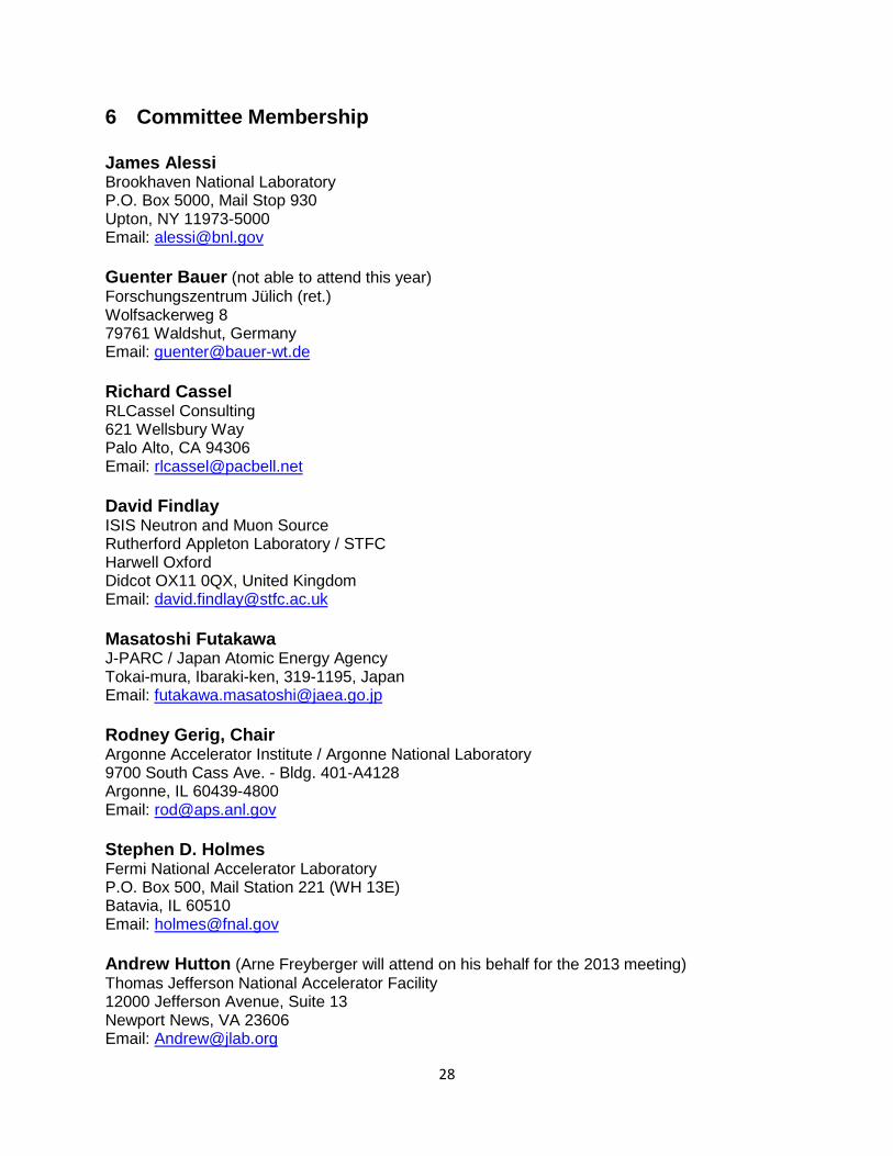
6 Committee Membership
James Alessi Brookhaven National Laboratory P.O. Box 5000, Mail Stop 930 Upton, NY 11973-5000 Email: [email protected]
Guenter Bauer (not able to attend this year) Forschungszentrum Jülich (ret.) Wolfsackerweg 8 79761 Waldshut, Germany Email: [email protected]
Richard Cassel RLCassel Consulting 621 Wellsbury Way Palo Alto, CA 94306 Email: [email protected]
David Findlay ISIS Neutron and Muon Source Rutherford Appleton Laboratory / STFC Harwell Oxford Didcot OX11 0QX, United Kingdom Email: [email protected]
Masatoshi Futakawa J-PARC / Japan Atomic Energy Agency Tokai-mura, Ibaraki-ken, 319-1195, Japan Email: [email protected]
Rodney Gerig, Chair Argonne Accelerator Institute / Argonne National Laboratory 9700 South Cass Ave. - Bldg. 401-A4128 Argonne, IL 60439-4800 Email: [email protected]
Stephen D. Holmes Fermi National Accelerator Laboratory P.O. Box 500, Mail Station 221 (WH 13E) Batavia, IL 60510 Email: [email protected]
Andrew Hutton (Arne Freyberger will attend on his behalf for the 2013 meeting) Thomas Jefferson National Accelerator Facility 12000 Jefferson Avenue, Suite 13 Newport News, VA 23606 Email: [email protected]

29
Robert J. Macek Los Alamos National Laboratory (ret.) 163 Laguna Street Los Alamos, NM 87544 Email: [email protected]
John Maclean Advanced Photon Source / Argonne National Laboratory 9700 South Cass Ave. - Bldg. 401-B4169 Argonne, IL 60439-4800 Email: [email protected]
Eric Pitcher European Spallation Source ESS AB P.O. Box 176 221 00 Lund, Sweden Email: [email protected]
Dieter Proch Buchenstr. 40 25462 Rellingen, Germany Email: [email protected]
Martha Zumbro Los Alamos National Laboratory MS H809 Los Alamos, NM 87545 Email: [email protected]
********************************* Substitutes: Freyberger, Arne Thomas Jefferson National Accelerator Facility 12000 Jefferson Avenue, Suite 19 Newport News, VA 23606 Email: [email protected]

30
7 Agenda for the Fifth Meeting
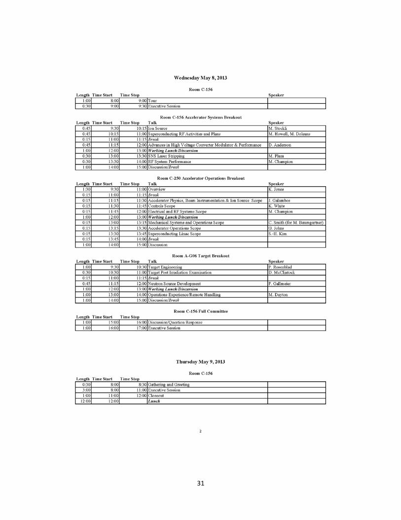
31