Report (Auto Capture Camera Sensing System)
21
1 Bachelor of Engineering / Science Electronic Engineering Module Laboratory Reports Bachelor of Engineering / Science in Electronic Engineering Data Structures and Algorithms Lee Siang Wei Semester 1 Academic Year 2014/15 Department of Engineering Technology School of Engineering Waterford Institute of Technology, Ireland.
-
Upload
jack-lee-siang-wei -
Category
Engineering
-
view
92 -
download
2
Transcript of Report (Auto Capture Camera Sensing System)

1
Bachelor of Engineering / Science
Electronic Engineering
Module Laboratory Reports
Bachelor of Engineering / Science
in Electronic Engineering
Data Structures and Algorithms
Lee Siang Wei
Semester 1
Academic Year 2014/15
Department of Engineering Technology
School of Engineering
Waterford Institute of Technology,
Ireland.

2
Table of contents
Introduction
What is mbed 3
Scope of project 4
Hardware
Details of main components 5-6
Block diagram 7
Wiring diagram 7-8
Description 8
Software
Overview 9-11
Implementation & Testing
Implementation step by step guides 12-14
Testing & Results 15-17
Problems Encountered 18
Future Recommendations 18
References 18
Appendices 19-21
3
Introduction
What is mbed?
mbed is a platform for developing smart devices that are based on 32-bit ARM
Cortex-M microcontrollers. It is designed to provide a highly productive solution for
rapid prototyping and product development, with a focus on connected Internet of
Things devices.
It is a project developed by ARM, its technology partners and a community of core
developers, and it is used by tens of thousands of professional developers to create
intelligent products that take advantage of the power of modern microcontrollers and
connectivity. The mbed microcontroller was the first hardware used to bootstrap the
mbed platform, used for creating smart devices based on ARM Cortex-M
microcontrollers.
The mbed software development kit (SDK) provides the mbed C/C++ software
platform and tools for creating microcontroller firmware that runs on smart devices. It
consists of the core libraries that provide the microcontroller peripheral drivers,
networking, RTOS and runtime environment, build tools and test and debug scripts. A
components database provides driver libraries for components and services that can
be connected to the microcontrollers to build a final product.
The mbed hardware development kit (HDK) provides the recipes to build custom
hardware for devices that support the mbed SDK. This consists of interface firmware
and schematics of the microcontroller subsystems that can be used to easily create
development boards, OEM modules and re-programmable/hackable products suitable
for production and that can take advantage of the mbed software platform and
development tools. There are various hardware platforms based on the HDK available,
with the first platform being the original mbed Microcontroller board used to
bootstrap the project.
The mbed platform now supports different ARM Cortex-M hardware though porting
of the mbed SDK to support new microcontrollers, and use of the mbed HDK to
create custom boards that support the software platform.

4
Scope of project
The scope of this project is that to capture a photo for a racing car when the sensor
detects the motion of itself before reaching the final line. The photo will then save
into a SD memory card.
5
Hardware
Details of main components
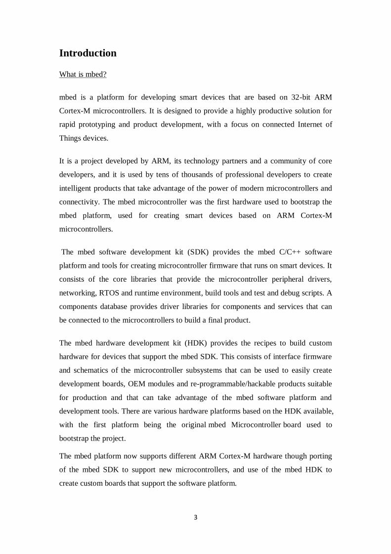
In the construction of this project, it consists of some of the main components: mbed
LPC1768, PIR Motion Sensor, LS-Y201 Camera and Breakout Board for microSD.
The mbed Microcontroller (more precisely mbed NXP LPC17680) is based around an
NXP microcontroller, which has an ARM Cortex M3 core, running at 96 MHz, with
512 KB flash, 64 KB RAM, as well as several interfaces including Ethernet, USB
Device, CAN, SPI, I²C and other I/O. It is the most important part of this project as it
control all the activities of the project.
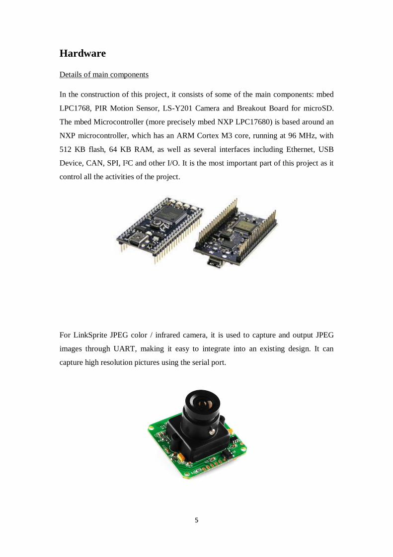
For LinkSprite JPEG color / infrared camera, it is used to capture and output JPEG
images through UART, making it easy to integrate into an existing design. It can
capture high resolution pictures using the serial port.
6
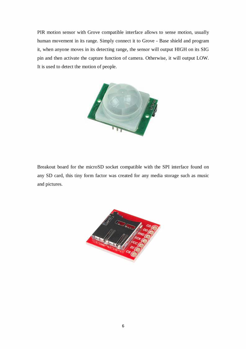
PIR motion sensor with Grove compatible interface allows to sense motion, usually
human movement in its range. Simply connect it to Grove - Base shield and program
it, when anyone moves in its detecting range, the sensor will output HIGH on its SIG
pin and then activate the capture function of camera. Otherwise, it will output LOW.
It is used to detect the motion of people.
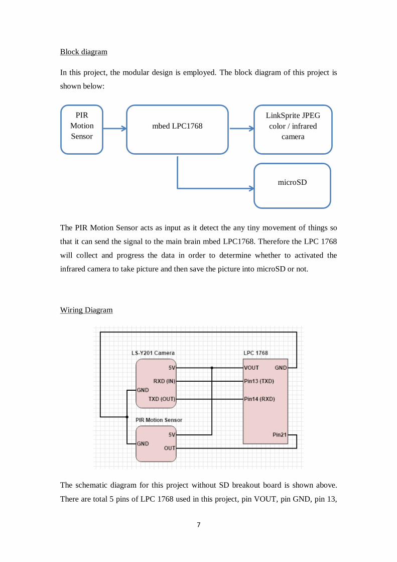
Breakout board for the microSD socket compatible with the SPI interface found on
any SD card, this tiny form factor was created for any media storage such as music
and pictures.
7
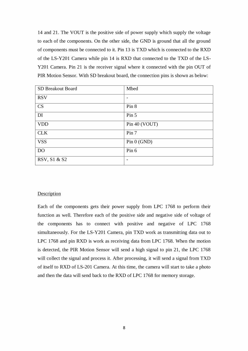
Block diagram
In this project, the modular design is employed. The block diagram of this project is
shown below:
The PIR Motion Sensor acts as input as it detect the any tiny movement of things so
that it can send the signal to the main brain mbed LPC1768. Therefore the LPC 1768
will collect and progress the data in order to determine whether to activated the
infrared camera to take picture and then save the picture into microSD or not.
Wiring Diagram
The schematic diagram for this project without SD breakout board is shown above.
There are total 5 pins of LPC 1768 used in this project, pin VOUT, pin GND, pin 13,
PIR
Motion
Sensor
mbed LPC1768
microSD
LinkSprite JPEG
color / infrared
camera
8
14 and 21. The VOUT is the positive side of power supply which supply the voltage
to each of the components. On the other side, the GND is ground that all the ground
of components must be connected to it. Pin 13 is TXD which is connected to the RXD
of the LS-Y201 Camera while pin 14 is RXD that connected to the TXD of the LS-
Y201 Camera. Pin 21 is the receiver signal where it connected with the pin OUT of
PIR Motion Sensor. With SD breakout board, the connection pins is shown as below:
SD Breakout Board Mbed
RSV -
CS Pin 8
DI Pin 5
VDD Pin 40 (VOUT)
CLK Pin 7
VSS Pin 0 (GND)
DO Pin 6
RSV, S1 & S2 -
Description
Each of the components gets their power supply from LPC 1768 to perform their
function as well. Therefore each of the positive side and negative side of voltage of
the components has to connect with positive and negative of LPC 1768
simultaneously. For the LS-Y201 Camera, pin TXD work as transmitting data out to
LPC 1768 and pin RXD is work as receiving data from LPC 1768. When the motion
is detected, the PIR Motion Sensor will send a high signal to pin 21, the LPC 1768
will collect the signal and process it. After processing, it will send a signal from TXD
of itself to RXD of LS-201 Camera. At this time, the camera will start to take a photo
and then the data will send back to the RXD of LPC 1768 for memory storage.
9
Software
The software is designed in order to support the effectiveness of the hardware device.
The software was written in C language, and was written in sections for easy
debugging and troubleshooting. Each section is tailored to meet the duty that will be
imposed on the corresponding hardware unit.
Overview
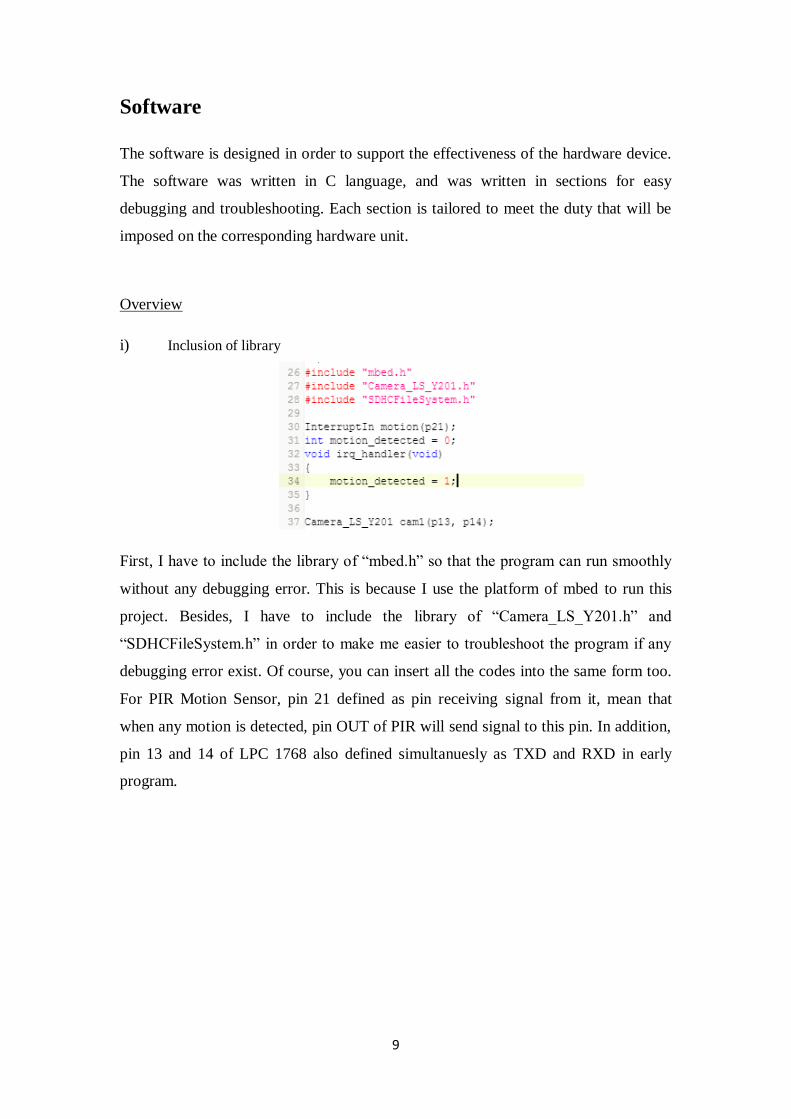
i) Inclusion of library
First, I have to include the library of “mbed.h” so that the program can run smoothly
without any debugging error. This is because I use the platform of mbed to run this
project. Besides, I have to include the library of “Camera_LS_Y201.h” and
“SDHCFileSystem.h” in order to make me easier to troubleshoot the program if any
debugging error exist. Of course, you can insert all the codes into the same form too.
For PIR Motion Sensor, pin 21 defined as pin receiving signal from it, mean that
when any motion is detected, pin OUT of PIR will send signal to this pin. In addition,
pin 13 and 14 of LPC 1768 also defined simultanuesly as TXD and RXD in early
program.
10
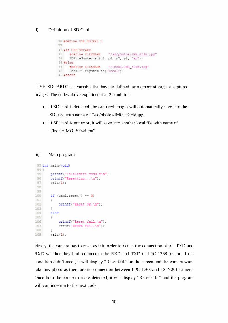
ii) Definition of SD Card
“USE_SDCARD” is a variable that have to defined for memory storage of captured
images. The codes above explained that 2 condition:
if SD card is detected, the captured images will automatically save into the
SD card with name of “/sd/photos/IMG_%04d.jpg”
if SD card is not exist, it will save into another local file with name of
“/local//IMG_%04d.jpg”
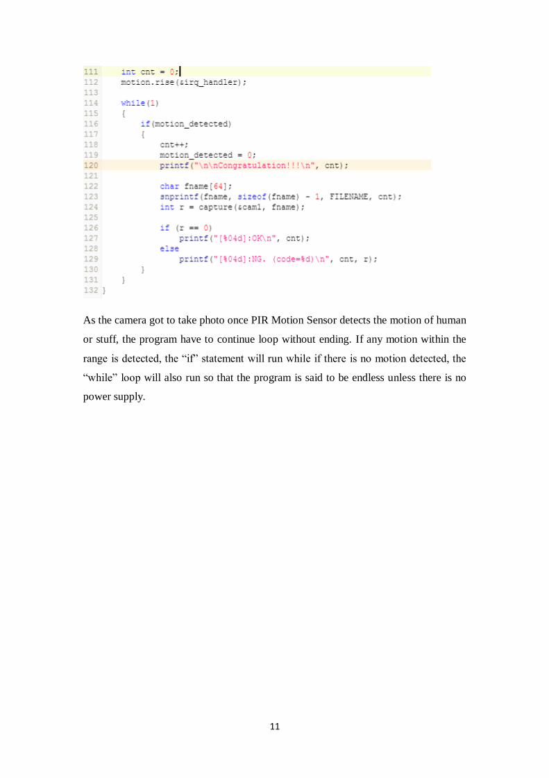
iii) Main program
Firstly, the camera has to reset as 0 in order to detect the connection of pin TXD and
RXD whether they both connect to the RXD and TXD of LPC 1768 or not. If the
condition didn’t meet, it will display “Reset fail.” on the screen and the camera wont
take any photo as there are no connection between LPC 1768 and LS-Y201 camera.
Once both the connection are detected, it will display “Reset OK.” and the program
will continue run to the next code.
11
As the camera got to take photo once PIR Motion Sensor detects the motion of human
or stuff, the program have to continue loop without ending. If any motion within the
range is detected, the “if” statement will run while if there is no motion detected, the
“while” loop will also run so that the program is said to be endless unless there is no
power supply.
12
Implementation & Testing
Implementation step by step guides
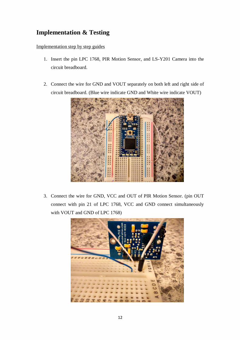
1. Insert the pin LPC 1768, PIR Motion Sensor, and LS-Y201 Camera into the
circuit breadboard.
2. Connect the wire for GND and VOUT separately on both left and right side of
circuit breadboard. (Blue wire indicate GND and White wire indicate VOUT)
3. Connect the wire for GND, VCC and OUT of PIR Motion Sensor. (pin OUT
connect with pin 21 of LPC 1768, VCC and GND connect simultaneously
with VOUT and GND of LPC 1768)
13
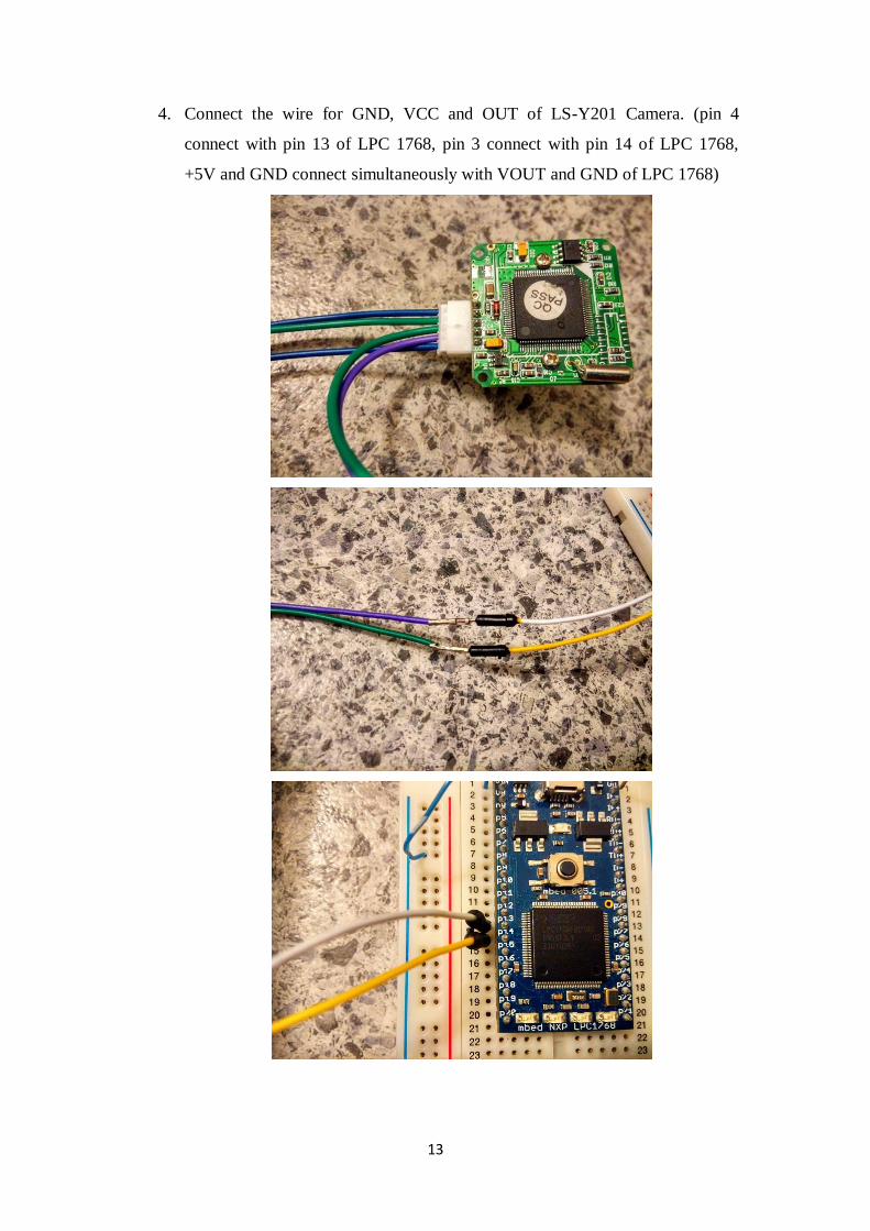
4. Connect the wire for GND, VCC and OUT of LS-Y201 Camera. (pin 4
connect with pin 13 of LPC 1768, pin 3 connect with pin 14 of LPC 1768,
+5V and GND connect simultaneously with VOUT and GND of LPC 1768)
14
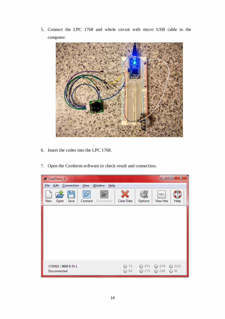
5. Connect the LPC 1768 and whole circuit with micro USB cable to the
computer.
6. Insert the codes into the LPC 1768.
7. Open the Coolterm software to check result and connection.
15
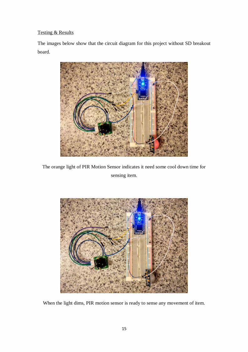
Testing & Results
The images below show that the circuit diagram for this project without SD breakout
board.
The orange light of PIR Motion Sensor indicates it need some cool down time for
sensing item.
When the light dims, PIR motion sensor is ready to sense any movement of item.
16
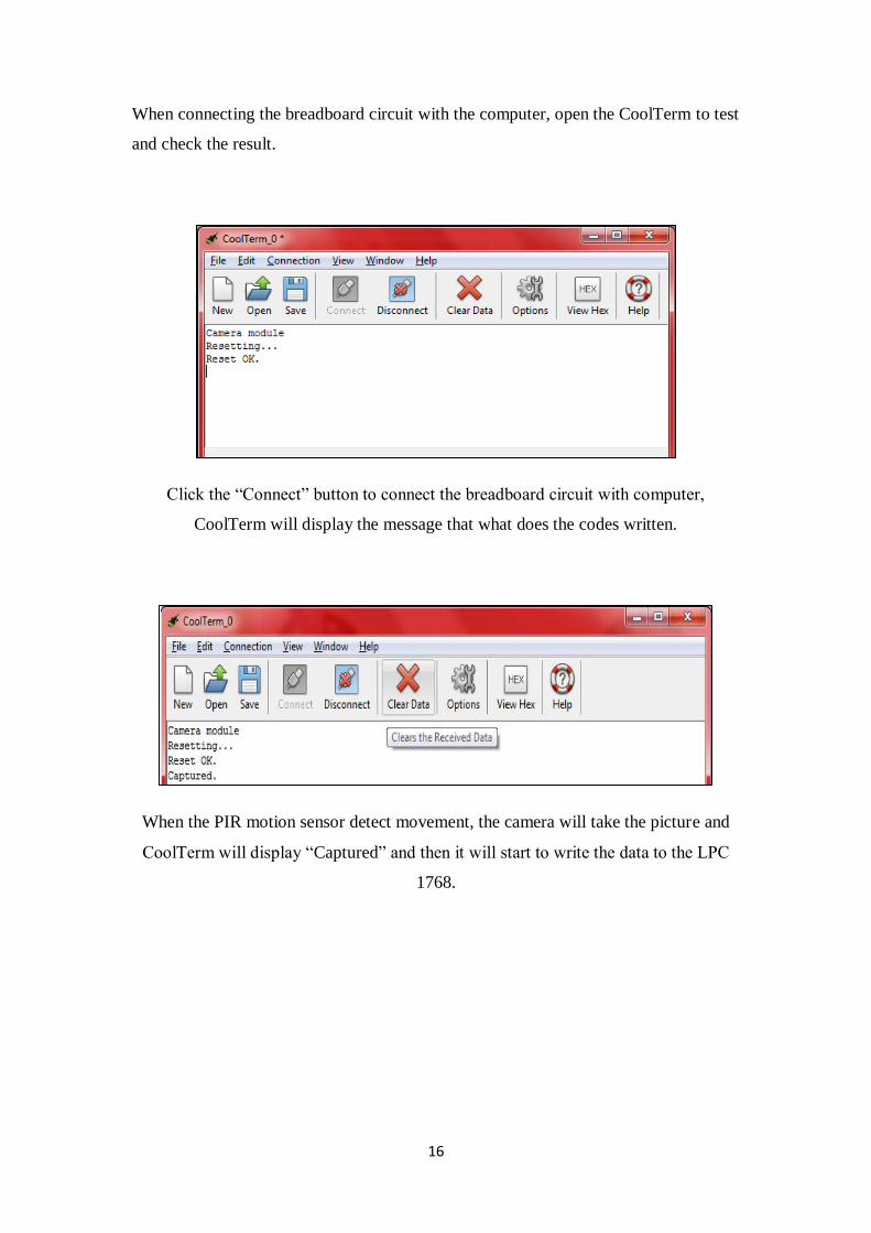
When connecting the breadboard circuit with the computer, open the CoolTerm to test
and check the result.
Click the “Connect” button to connect the breadboard circuit with computer,
CoolTerm will display the message that what does the codes written.
When the PIR motion sensor detect movement, the camera will take the picture and
CoolTerm will display “Captured” and then it will start to write the data to the LPC
1768.
17
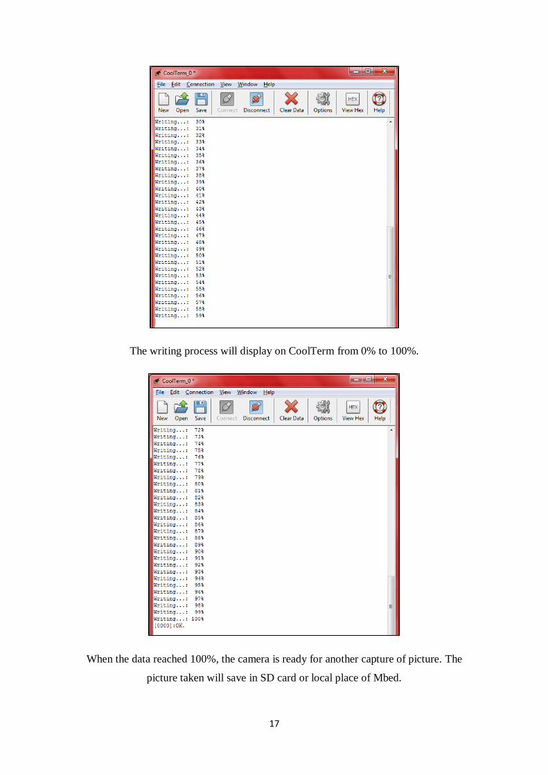
The writing process will display on CoolTerm from 0% to 100%.
When the data reached 100%, the camera is ready for another capture of picture. The
picture taken will save in SD card or local place of Mbed.
18
Problems Encountered
In this project, there are some of problems to be solved. The sensor that I used at very
early stage was infrared sensor, during implementation stage, the sensor can’t detect
any movement and this causes the camera always wait for the sensing to take the
photo. I took lots of time to troubleshoot the problem and it still no working.
Therefore, I decided to use PIR Motion Sensor to replace the infrared sensor and the
whole circuit works as well. Besides, for the coding of SD card, I also please the help
of my friends, Zhen Jing Heng to identify the problems when the photo cannot save
into the SD card. All these problems are hard to be identified with its death root
causes but luckily with the help of some friends and guidance from lecturers, the
problems are solved.
Future Recommendations for this project
As the sensor that using in this project was PIR Motion Sensor, it is very sensitive to
the motion from 360 degrees within the range of sensing. When there is a little bit of
movement within the range, it will quickly detected and then send the signal to the
LPC 1768 for further activities. Besides, it also need some cool down time to ready
for another detection of motion. Therefore, I recommend that using the infrared sensor
as it only detect the motion once the motion is cut off.
References
http://en.wikipedia.org/wiki/Mbed
http://en.wikipedia.org/wiki/Mbed_microcontroller
19
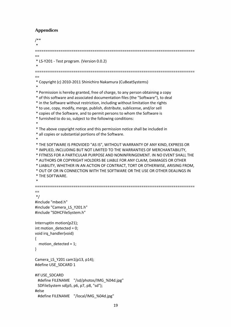
Appendices
/** * ============================================================================= * LS-Y201 - Test program. (Version 0.0.2) * ============================================================================= * Copyright (c) 2010-2011 Shinichiro Nakamura (CuBeatSystems) * * Permission is hereby granted, free of charge, to any person obtaining a copy * of this software and associated documentation files (the "Software"), to deal * in the Software without restriction, including without limitation the rights * to use, copy, modify, merge, publish, distribute, sublicense, and/or sell * copies of the Software, and to permit persons to whom the Software is * furnished to do so, subject to the following conditions: * * The above copyright notice and this permission notice shall be included in * all copies or substantial portions of the Software. * * THE SOFTWARE IS PROVIDED "AS IS", WITHOUT WARRANTY OF ANY KIND, EXPRESS OR * IMPLIED, INCLUDING BUT NOT LIMITED TO THE WARRANTIES OF MERCHANTABILITY, * FITNESS FOR A PARTICULAR PURPOSE AND NONINFRINGEMENT. IN NO EVENT SHALL THE * AUTHORS OR COPYRIGHT HOLDERS BE LIABLE FOR ANY CLAIM, DAMAGES OR OTHER * LIABILITY, WHETHER IN AN ACTION OF CONTRACT, TORT OR OTHERWISE, ARISING FROM, * OUT OF OR IN CONNECTION WITH THE SOFTWARE OR THE USE OR OTHER DEALINGS IN * THE SOFTWARE. * ============================================================================= */ #include "mbed.h" #include "Camera_LS_Y201.h" #include "SDHCFileSystem.h" InterruptIn motion(p21); int motion_detected = 0; void irq_handler(void) { motion_detected = 1; } Camera_LS_Y201 cam1(p13, p14); #define USE_SDCARD 1 #if USE_SDCARD #define FILENAME "/sd/photos/IMG_%04d.jpg" SDFileSystem sd(p5, p6, p7, p8, "sd"); #else #define FILENAME "/local/IMG_%04d.jpg"
20
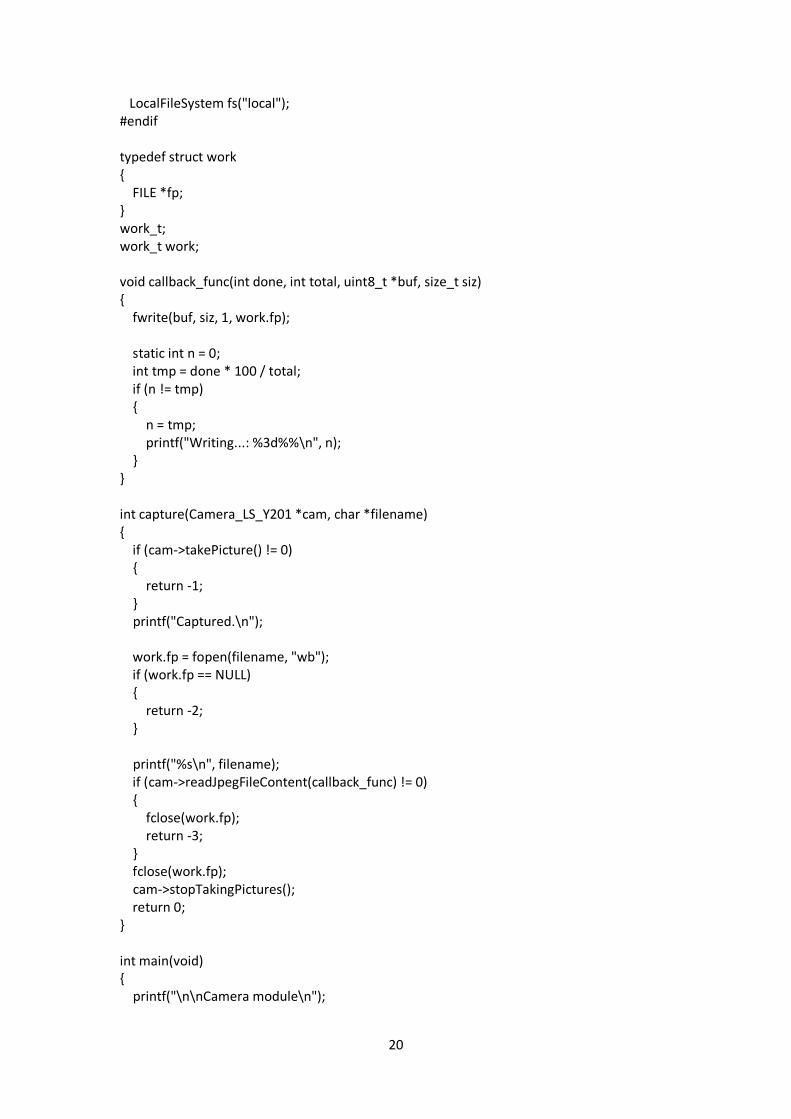
LocalFileSystem fs("local"); #endif typedef struct work { FILE *fp; } work_t; work_t work; void callback_func(int done, int total, uint8_t *buf, size_t siz) { fwrite(buf, siz, 1, work.fp); static int n = 0; int tmp = done * 100 / total; if (n != tmp) { n = tmp; printf("Writing...: %3d%%\n", n); } } int capture(Camera_LS_Y201 *cam, char *filename) { if (cam->takePicture() != 0) { return -1; } printf("Captured.\n"); work.fp = fopen(filename, "wb"); if (work.fp == NULL) { return -2; } printf("%s\n", filename); if (cam->readJpegFileContent(callback_func) != 0) { fclose(work.fp); return -3; } fclose(work.fp); cam->stopTakingPictures(); return 0; } int main(void) { printf("\n\nCamera module\n");
21
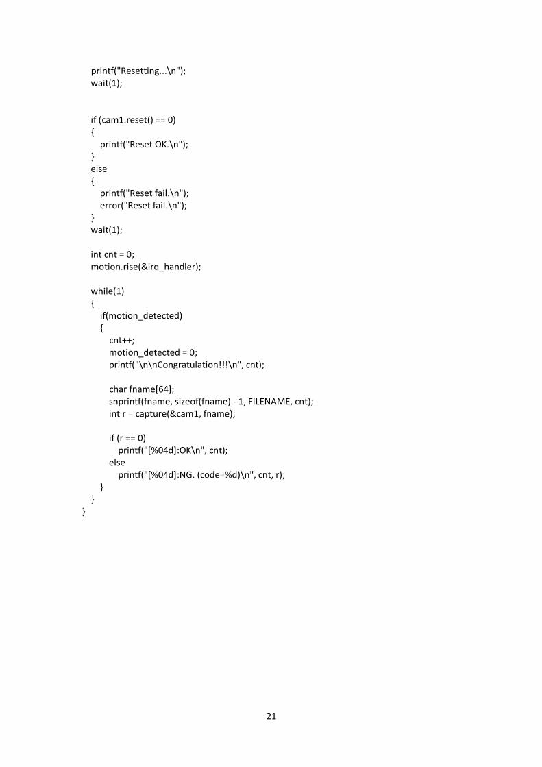
printf("Resetting...\n"); wait(1); if (cam1.reset() == 0) { printf("Reset OK.\n"); } else { printf("Reset fail.\n"); error("Reset fail.\n"); } wait(1); int cnt = 0; motion.rise(&irq_handler); while(1) { if(motion_detected) { cnt++; motion_detected = 0; printf("\n\nCongratulation!!!\n", cnt); char fname[64]; snprintf(fname, sizeof(fname) - 1, FILENAME, cnt); int r = capture(&cam1, fname); if (r == 0) printf("[%04d]:OK\n", cnt); else printf("[%04d]:NG. (code=%d)\n", cnt, r); } } }