REOI FOR KU-BAND GROUND STATION FOR GISAT -EOI-001.pdf · March, 2015 REOI FOR KU-BAND GROUND...
21
March, 2015 REOI FOR KU-BAND GROUND STATION FOR GISAT SDR&ISA / NRSC i ISRO-NRSC-STSG -EOI-001 Request for Expression of Interest (REoI) for Supply, Installation & Commissioning Of Ku-BAND GROUND STATION FOR GEO IMAGING SATELLITES March 2015 Satellite Tracking Systems Group Satellite Data Acquisition Products and Services Area National Remote Sensing Centre Indian Space Research Organization Balanagar, Hyderabad-500625
Transcript of REOI FOR KU-BAND GROUND STATION FOR GISAT -EOI-001.pdf · March, 2015 REOI FOR KU-BAND GROUND...

March, 2015 REOI FOR KU-BAND GROUND STATION FOR GISAT
SDR&ISA / NRSC i
ISRO-NRSC-STSG -EOI-001
Request for Expression of Interest (REoI) for
Supply, Installation & Commissioning
Of
Ku-BAND GROUND STATION FOR GEO IMAGING SATELLITES
March 2015
Satellite Tracking Systems Group Satellite Data Acquisition Products and Services Area
National Remote Sensing Centre Indian Space Research Organization
Balanagar, Hyderabad-500625

March, 2015 REOI FOR KU-BAND GROUND STATION FOR GISAT
SDR&ISA / NRSC ii
Contents
1 Introduction ............................................................................................................. 1
2 Scope of the work ................................................................................................... 2
3 Overall Technical Specifications ............................................................................. 4
4 System Description ................................................................................................. 6
5 RF Systems ............................................................................................................ 8
6 Antenna Control Servo Systems ............................................................................. 9
7 Mechanical Systems ............................................................................................. 12
8 Reliability & QA requirements ............................................................................... 14
9 Delivery Schedule ................................................................................................. 15
10 System Installation & Integration .......................................................................... 15
11 Acceptance Test plan ........................................................................................... 15
12 Vendor details ....................................................................................................... 16
March, 2015 REOI FOR KU-BAND GROUND STATION FOR GISAT
SDR&ISA / NRSC iii
LIST OF TABLES
Table 3-1: Technical Specifications of Ku-band Antenna System ..................................................................... 4
Table 6-1: ACSS Specifications ........................................................................................................................ 9
Table 6-2: ACU Specifications ....................................................................................................................... 10
Table 8-1: Indoor Unit Environmental Specifications .................................................................................... 14
Table 8-2: Outdoor Unit Environmental Specifications ................................................................................. 14
Table 12-1: Vendor details ........................................................................................................................... 16
LIST OF FIGURES
Figure 4-1: Ku-band antenna system .............................................................................................................. 7

March, 2015 REOI FOR KU-BAND GROUND STATION FOR GISAT
SDR&ISA / NRSC 1
1 Introduction
National Remote Sensing Centre (NRSC) is one of the prime centres of Indian Space
Research Organization (ISRO) under Department of Space, Government of India. The
prime responsibility of NRSC is acquisition of Earth Observation Data from Remote
Sensing Satellites, product generation & Dissemination as well as application
development, Aerial services and capacity building.
ISRO is planning to launch GISAT (Geo-Imaging Satellite) to meet National Disaster
Management requirements. Geo-Imaging spacecraft was conceived with the objective “
To tap new functionalities hitherto not covered by existing LEO & GEO Missions like fast
revisit capability, real time monitoring, high resolution multi spectral and Hyper spectral
imaging all on a single, agile, jitter free platform ”.
The objective of this document is to locate suitable vendors, who would be interested
and capable of establishing the Ku-band Remote Sensing Ground Station for GEO
Imaging satellites. The vendors shall have an experience in the establishment of
Antenna Systems for tracking and receiving data from LEO/GEO satellites.
Based on the information provided in this document, Vendors should come forward and
have technical discussions with NRSC to completely understand the requirements.
This document provides the preliminary information of Ku-band Remote Sensing
Ground Station intended to be established. The details and requirements identified in
this document may undergo some changes due to the on-going refinement of the
requirements and based on discussions with the vendors in order to make it most
suitable for intended applications.
The final Request for Proposal (RFP) will be prepared after detailed discussions with
vendors and will include the final specifications. The vendors should provide budgetary
estimates along with delivery schedules for different possible options/configurations.
March, 2015 REOI FOR KU-BAND GROUND STATION FOR GISAT
SDR&ISA / NRSC 2
The work includes supply, installation and commissioning of Ku-band Remotes Sensing
Ground stations at three different locations in India. The ground station should have the
capability to track the GISAT series of satellites in GEO orbit. GISAT transmits payload
data in Ku band with an EIRP of 43dBW and its frequency range is from 12.25 to 12.45
GHz at 200 Mbps data rate using QPSK Modulation scheme.
2 Scope of the work
NRSC intends to entrust the task of supply and installation of ‘Ku-band Remote sensing
Ground Station’ to an industry on turnkey basis. The implementation of the project
includes system engineering, design/development, preparation of drawings, antenna
foundation design, civil works, supply, installation and commissioning of complete Ku-
band ground station.
The Vendor as an entity is fully responsible for supply and installation of the ‘Ku-band
remote sensing ground station' either independently or with sub vendors. NRSC invites
interested vendors to submit response to Expression of Interest (EOI) for the
establishment of Ku-band Remote Sensing Ground Station. The vendor is requested to
submit following:
• Expression of interest for the execution of the work
• Vendor details as per table 12-1.
• Compliance of understanding the REoI document
• Detailed technical proposal
• Bill of material
• Budgetary proposal
• Delivery Schedules
The Supply and installation of ‘Ku-band Remote Sensing Ground Station’ will involve
(not limited to) the following minimum activities as under:
• Understanding and finalization of the requirements

March, 2015 REOI FOR KU-BAND GROUND STATION FOR GISAT
SDR&ISA / NRSC 3
• Design/ Development & System Engineering
• Supply of various Hardware/ Software systems
• Site Preparation Support (Inputs in the form of details/drawings for electrical
and other requirements for installation at user site)
• Equipment Transportation to site
• Installation and Commissioning
• Documentation, User manual and Training
• Technical support/ Technology upgrades for at least ten years
• Warranty & post warranty services
• Supply of required interfacing cables of all types, waveguides, patch panel,
patch cords, coaxial connector, etc.
The project management team of NRSC will periodically review the technical,
commercial and managerial aspects of the activity.
The typical reviews will be as under:
• Preliminary Design Review
• Critical Design Review
• Factory Acceptance Tests
• Final On Site Acceptance Tests
The vendor has to provide the appropriate drawings/ details wherever NRSC System
interface is involved.

March, 2015 REOI FOR KU-BAND GROUND STATION FOR GISAT
SDR&ISA / NRSC 4
3 Overall Technical Specifications
Table 3-1: Technical Specifications of Ku-band Antenna System
Sl. No PARAMETERS SPECIFICATIONS
1. Frequency Range 10.70 GHz to 12.75 GHz 2. Reflector size Minimum of 9 meter diameter, aluminum alloy 3. Feed Configuration Cassegrain, Monopulse, Receive only, Two port
4. Reflector surface accuracy Better than 0.3mm rms
5. Sub reflector surface accuracy Better than 0.05 mm
6. Polarization Linear, Simultaneous Vertical and Horizontal orient able
7. Ku-band G/T Better than 38dB/0K @ 200 Elevation over full range
8. Antenna Mount Elevation Over Azimuth
9. Type of Servo Drive Geared Servo motor with feedback
10. Operating modes Manual/ Slew / Auto track /Step Track/ Program Track
11. Azimuth Travel range 0 to 140deg Continuous See Note1
12. Elevation Travel range 0 to 90deg Continuous
13. Velocity(Azimuth & elevation
Minimum 0.050/sec Maximum 0.250/sec
14. Travel Limits
Hardware and Software Limits for 1) Azimuth CW, CCW 2) Elevation UP, DOWN 3) Polarization CW, CCW
15. Polarization Travel ± 55Deg, CW and CCW, Motorized, Remote Control and Manual Control.
16. Pointing Error(RSS Peak)
Maximum 1/5th of 3dB beam width at operational wind velocity and occasional gust
17. Tracking Error(RSS Peak)
Maximum 1/10th of 3dB beam width at operational wind velocity and occasional gust
18. Angle Display Resolution
0.001deg in Azimuth & Elevation 0.01deg for polarization
19. Feed VSWR 1.3:1 (Maximum)
20. Radiation patterns & side lobe levels As per ITU-R Rec.580-5
21. First Side Lobe Level Minimum 14dB below main lobe

March, 2015 REOI FOR KU-BAND GROUND STATION FOR GISAT
SDR&ISA / NRSC 5
22. Cross polarization Isolation 33dB minimum within 1dB beam width
23. LNA System Tri-redundant configuration( 2 LNA active)
24. Input Signal for Tracking
1) Beacon Signal The Beacon tracking receiver to work in AFC mode for this input tracking signal.
2) Wide band QPSK modulated carrier. 25. L-band IF frequency 950MHz – 1750 MHz
26. Spurious @ receive IF port at nominal output power
Less than – 65dBc
27. Spurious (signal independent) Less than -75 dBc
28. Modulation Type BPSK/QPSK/OQPSK/8PSK with convolution coding FEC 7/8 and RS(255,239) decoder
29. Data rate Minimum 220Mbps Option1: 250 Mbps Max Option 2 320 Mbps Max
30. BER Performance 1.0 x 10⁻⁸ at 7dB Eb/N0 31. Monitoring & Control Local/Remote (Ethernet with TCP/IP Protocol) 32. Pressurization 9 to 30 g/cm2, Nominal
33. Pressurization Leakage rate
200cc / Hour, Max
34. wind Velocity Operational: 70kmph, Min Survival (on stow): 200Kmph, Min
Vendor can suggest latest technologies to achieve better performance in their quotes.
NOTE1: If required, in future, any azimuth angle should be settable from the initial angle to
point to the other satellite at any of the orbital slots ranging from 480E to 115
0E and an
inclination of ± 5 deg, without disturbing the pedestal.

March, 2015 REOI FOR KU-BAND GROUND STATION FOR GISAT
SDR&ISA / NRSC 6
4 System Description
The required Ku-band ground station shall have G/T of 38dB/0K and its configuration is
shown in Figure 4.1. The diameter of the antenna can be between 9 to 11 Meters with
cassegrain configuration. The feed also should have the capability for polarization
adjustment. The signal is received by the Antenna after low noise amplification; it is
down converted to 720 MHz IF. All the specifications mentioned in Table-3.1 should
meet the Ku-band frequency range of 10.70 GHz to 12.75 GHz. Vendor can suggest latest
technologies to achieve better performance in their quotes. The FO links chosen for IF
data transfer is of single mode fibre with sufficient band width to support complete Ku-
band range.
The GISAT configuration does not have On-board beacon, vendor has to suggest
alternative to beacon tracking apart from Monopulse auto track as requested by NRSC.
The proposed servo system should have auto tracking capability in Ku band. As the
antenna beam width for Ku band is relatively small when compared to X-band, it is
essential to maintain the pointing accuracy within one fifth of the beam width in order to
receive maximum signal without any loss. The antenna system to withstand to heavy
winds, earth quakes, against vibrations etc. The control system along with drive units
has to be planned in the pedestal room along with necessary test equipment.
The required antenna system should consists of following:
� Ku band Antenna & feed system.
� Ku band down converter.
� Tracking receiver
� High Data rate Demodulator
� Antenna Control unit
� Antenna Motor and Drive System
� Elevation over Azimuth pedestal.
� Network Time Protocol (NTP) server.

March, 2015 REOI FOR KU-BAND GROUND STATION FOR GISAT
SDR&ISA / NRSC 7
Ku-band
Antenna &
feed system
Ku-band
Down
Converter
High data
rate
Demodulator
Tracking
Receiver
Antenna
Control Unit
Motor &
Drive System NTP Server
FO Link
Figure 4-1: Ku-band antenna system
March, 2015 REOI FOR KU-BAND GROUND STATION FOR GISAT
SDR&ISA / NRSC 8
5 RF Systems RF Systems comprises of Antenna feed, feed electronics, down converters, tracking
receivers etc.
The Antenna system shall have main reflector in parabola shape and sub reflector in
hyperbola shape and feed in Cassegrain configuration. The required G/T of 38dB/0K
has to be demonstrated at 200 Elevation. A low noise amplifier with best possible Gain
and Noise temperature has to be proposed to keep the diameter close to 9 Meters. The
feed also should support mono pulse auto track configuration.
Data and tracking signals from feed ports shall be down converted from Ku band to
720MHz IF using single/two stage down conversion. All the up-down converters should
have built in synthesizes to program LO frequency. The sub systems can be placed
near to the feed to reduce the cable loss from feed to pedestal room. First Data down
converter outputs from pedestal are driven through fibre optic link to the control room.
Independent FO links are required for RF and Tracking. Second Data down converter
will be placed in control room. The IF signals is demodulated and decoded for data
ingestion and further processing. Vendor can also offer the other solution which takes L
band input directly without the second down converter (L-band to 720 MHz).
The beacon tracking not possible to track GISAT, as On-board beacon is not available.
So an alternate tracking mechanisms have to be proposed by the vendor to meet the
real-time tracking requirements apart from Step tracking.
March, 2015 REOI FOR KU-BAND GROUND STATION FOR GISAT
SDR&ISA / NRSC 9
6 Antenna Control Servo Systems
ACSS should have access both from the control room and antenna pedestal room. The
real-time operations are supported from the control room and Antenna maintenance
activities will be carried out at pedestal room. All the sub systems should have Ethernet
interface with TCP/IP support. Encoder & limit switch assembly should use precision
gearing mechanism with anti backlash facility, directly fixed to SRB with hollow shaft as
main encoder along with redundant encoder. The resolution of encoder should be 22
bits or better.
Table 6-1: ACSS Specifications
SL NO Parameter Description
1. Position display Resolution 0.001 deg or better
2. Programmable control
parameters
PID / LQG control gains and torque bias for
single/ dual drive configurations.
3. Position loop bandwidth 0.1 to 1.0 Hz typically Field programmable for
BW for single/ dual drive configurations.
4. Rate loop bandwidth 5.0 to 10.0 Hz Field programmable for single/
dual drive configurations.
5. Operating modes
Standby, Ready, Slew, Manual, Program,
Designate, Ku-Auto, Step, Sun/Star, Slave
modes.
6. Type of control system Type II Closed loop position control
7. Drive configuration Two motor Counter-torque (Torque bias)
8. Type of Motor Brushless AC servo motor with resolver
feedback and built in brake.
9. Type of Drive Space vector PWM drive compatible to above
motor
10. Digital Controller
Advanced controllers can be explored in
addition to PID and feed forward control
schemes.
Antenna Control Unit
Servo Controller must be a software configurable digital controller for implementing
precision closed loop servo control system for two axes. It must implement the functions
of Position loop through position feedback and torque bias function.

March, 2015 REOI FOR KU-BAND GROUND STATION FOR GISAT
SDR&ISA / NRSC 10
Table 6-2: ACU Specifications
SL No Parameter Value
1. Tracking modes Program Track,
Ku band Auto track
2. Manual Modes Standby, Manual, step, Slew, Stow, Designate & command
angle
3. Axes supported Azimuth, Elevation
4. Digital I/O channel 48 opto isolated
5. Analog – Digital
channels
12 channels with ± 10 Volts differential input and 16 bit
output
6. Digital – Analog
channel 10 channels with 16 bit input and ± 10 Volts output
Required features of ACU are:
• Software Configurable servo loops
• Real time data logging, fault indication and event logging
• Provision to give offsets to Azimuth, elevation and time during Real time
• Polarization control
• Time Synchronization to be better than 500 micro seconds
• Programmable Software and Hardware limits
• Self test diagnostic tools for all sub systems
• Antenna brake Protection circuit.
• safety limits and Interlocks
The antenna control software should have the capability track the satellite in real-time in
Auto track / step track / program track mode. The required functions of the Antenna
Control software are
• GUI to display the station configuration
• Positioning the antenna to satellite lookup angles
• Automatic configuration of the sub systems
• Control system software tools for modeling, estimation & compensation of
systematic errors of Antenna mount, Antenna droop etc.,
• Dynamic friction compensation
• Real time monitoring and data logging

March, 2015 REOI FOR KU-BAND GROUND STATION FOR GISAT
SDR&ISA / NRSC 11
• Implementing different tracking modes
• Implementing different acquisition modes
• Utilities to carryout different servo tests like velocity and acceleration tests,
gradient measurements, S curve, step response etc.
• Data logger to monitor and log different engineering parameters of ACSS
system.
• Display of safety limits and Interlocks
• Utilities to track Sun/Star
Antenna Motor & Drive System
Digital Drive Amplifiers must be high efficient 3 phase Space Vector PWM IGBT based
power amplifier to drive the brushless AC servo motor. There are total four power
amplifiers each axis will have two power amplifiers. Servo Controller with built in power
supply and Ethernet interface for configuration, control & monitoring of current, velocity,
fault & status indication. Suitable drive amplifier with the following features is required.
• Integrated Power Supply and controller with all the protection circuits.
• Dynamic brake facility.
• Configurable for Velocity / Torque modes
• Programmable control parameters
• Potential free contacts for interlocking the drive amplifier.
• Resolver/encoder interface
• Ethernet interface for remote monitoring & control
• Provision for monitoring current, faults, status etc.,
• Protection features

March, 2015 REOI FOR KU-BAND GROUND STATION FOR GISAT
SDR&ISA / NRSC 12
7 Mechanical Systems
Antenna Mount
The antenna required be mounted on Elevation over Azimuth drive Pedestal with
steerability of 0 to 90 deg in Elevation and 0 to 140 Deg in Azimuth in Continuous
mode to enable pointing the antenna to any GEO satellite. The Rigidity of the
mount, reflector & foundation should be able to provide the required pointing &
Tracking accuracies.
Mechanical considerations for Antenna Design
Following main factors have to be taken into account while designing the Structural and
mechanical elements of Antenna Reflector and Mount:
1. The 2 axes Antenna mount supporting structure shall be used for above assembly.
2. Axis Alignment i.e. Orthogonality between Azimuth and elevation axis.
3. Structural deformation due to wind, Temperature and gravity. The reflector back up
structure needs to be strengthened.
4. Minimum Gear backlash, less thermal deformation of reflector and encoder
alignment directly to the axis shaft to achieve the overall pointing accuracy.
5. Precise fabrication of mechanical components from reputable suppliers with proper
attention to stiffness of reducers, individual component testing and tight quality
control over tolerances specified.
6. Vendor shall be considered materials like oxygen free copper for the fabrication of
feed components.
7. The antenna pointing also depend upon precision structure that provide structural
stiffness in wind and low thermal effects, proper mechanical alignments of critical
components which requires care and skill during field installation.
March, 2015 REOI FOR KU-BAND GROUND STATION FOR GISAT
SDR&ISA / NRSC 13
8. The geometrical optics of the reflector – sub-reflector and feed alignment.
9. Antenna focusing – antenna focus alignment is very sensitive. Photogrammetric
and computer aided algorithm techniques are to be adopted for the antenna
alignment process along with skilled and experienced technician.
10. Total Antenna Error budget for pointing error has to be made and listed. The
overall pointing error should be less than the specified specifications.
11. The parameters considered for the pointing error should include all the systematic
and random errors.
12. The pedestal errors have to be made bare minimum with optimum design and high
precision machining and quality control.
13. Due to high pointing accuracy requirement, high precision fabrication of
mechanical components and sub-assemblies are to be carried. Stringent tolerance
specifications are to be made, measured and accounted properly.
14. Thermal protection and custom built high precision bearings (SRB) can be
explored. High precision Slew Ring Bearings with low bearing wobble are to be
chosen.
March, 2015 REOI FOR KU-BAND GROUND STATION FOR GISAT
SDR&ISA / NRSC 14
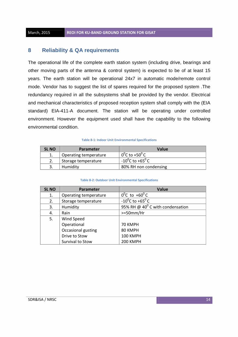
8 Reliability & QA requirements The operational life of the complete earth station system (including drive, bearings and
other moving parts of the antenna & control system) is expected to be of at least 15
years. The earth station will be operational 24x7 in automatic mode/remote control
mode. Vendor has to suggest the list of spares required for the proposed system .The
redundancy required in all the subsystems shall be provided by the vendor. Electrical
and mechanical characteristics of proposed reception system shall comply with the (EIA
standard) EIA-411-A document. The station will be operating under controlled
environment. However the equipment used shall have the capability to the following
environmental condition.
Table 8-1: Indoor Unit Environmental Specifications
SL NO Parameter Value
1. Operating temperature 00C to +50
0 C
2. Storage temperature -100C to +65
0 C
3. Humidity 80% RH non condensing
Table 8-2: Outdoor Unit Environmental Specifications
SL NO Parameter Value
1. Operating temperature 00C to +60
0 C
2. Storage temperature -100C to +65
0 C
3. Humidity 95% RH @ 400 C with condensation
4. Rain >=50mm/Hr
5. Wind Speed
Operational
Occasional gusting
Drive to Stow
Survival to Stow
70 KMPH
80 KMPH
100 KMPH
200 KMPH
March, 2015 REOI FOR KU-BAND GROUND STATION FOR GISAT
SDR&ISA / NRSC 15
9 Delivery Schedule
Vendor has to provide delivery schedules with major milestones like design reviews,
installation, Factory Acceptance Test etc.
10 System Installation & Integration
The vendor shall be responsible for installation and commissioning of the Ku-band
reception system at NRSC locations. Vendor should demonstrate its functionality in its
full configuration at user site for final acceptance. Final acceptance of the system will be
done only after installation at user site in its full configuration.
11 Acceptance Test plan
The system will undergo the acceptance tests as per the mutually agreed test plans at
the vendor’s site (factory acceptance test) as well as at the installation site (site
acceptance test) and user validation. The vendor will be responsible to arrange the tests
in the presence of NRSC engineers. The tests may be as per the sequence given below
with a detailed test plan and will be finalized latter.
• Subsystem level tests at Vendor’s/Manufacturer’s premises
• Sub system level test at user site after receipt of the systems
• Testing of antenna control and tacking system.
• Testing with complete antenna systems
• Simulation checks
• Testing of the earth station with spacecraft
• Final acceptance test plan as per NRSC laid down procedures
March, 2015 REOI FOR KU-BAND GROUND STATION FOR GISAT
SDR&ISA / NRSC 16
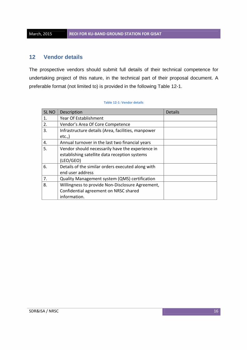
12 Vendor details
The prospective vendors should submit full details of their technical competence for
undertaking project of this nature, in the technical part of their proposal document. A
preferable format (not limited to) is provided in the following Table 12-1.
Table 12-1: Vendor details
SL NO Description Details
1. Year Of Establishment
2. Vendor’s Area Of Core Competence
3. Infrastructure details (Area, facilities, manpower
etc.,)
4. Annual turnover in the last two financial years
5. Vendor should necessarily have the experience in
establishing satellite data reception systems
(LEO/GEO)
6. Details of the similar orders executed along with
end user address
7. Quality Management system (QMS) certification
8. Willingness to provide Non-Disclosure Agreement,
Confidential agreement on NRSC shared
information.
March, 2015 REOI FOR KU-BAND GROUND STATION FOR GISAT
SDR&ISA / NRSC 17
NOTICE OF INTENT TO PRE-BID
REoI Title: Supply, Installation and Commissioning of Ku-band Ground station for
GEO imaging satellite
Vendors must complete and return this form to NRSC/ISRO. The undersigned person
has read all EoI instructions and requirements and will submit a proposal in compliance
with those instructions. Return this form to the name and address listed in this
document.
Company Name:
Name:
Title:
Address:
Telephone:
Fax:
Email:
Website:
Signature: Date:

March, 2015 REOI FOR KU-BAND GROUND STATION FOR GISAT
SDR&ISA / NRSC 18
Contact persons for any technical clarification
1. Group Head, STSG
National Remote Sensing Centre (NRSC), ISRO, Hyderabad-500625 Telephone: 23884296 Email: [email protected]
2. Group Head, SDSG
National Remote Sensing Centre (NRSC), ISRO, Hyderabad-500625 Telephone: 23884336 Email: [email protected]
3. Deputy Director, SDAPSA
National Remote Sensing Centre (NRSC), ISRO, Hyderabad-500625 Telephone: 2388 4434 Email: [email protected]
For further commercial information 4. Head, Purchase & Stores
National Remote Sensing Centre (NRSC), ISRO, Hyderabad-500625 Telephone: 2388 4072 Email: [email protected]
![Mott MacDonald Report Templatekwsb.gos.pk/SitePdfFiles/REOI Revenue Improvement Document.d… · Web view20201010 R00 REOI Revenue Improvement [Clean Sep 2020] GUL.docx i 29 October](https://static.fdocuments.us/doc/165x107/60a1b6a38361b41fdd3464de/mott-macdonald-report-revenue-improvement-documentd-web-view-20201010-r00-reoi.jpg)