Renewable Generation Project Guidelines - Nashville ...€¦ · Renewable Generation Project...
26
Renewable Generation Project Guidelines Version 1 Published by Nashville Electric Service Effective Date: August 15, 2012
Transcript of Renewable Generation Project Guidelines - Nashville ...€¦ · Renewable Generation Project...
Renewable Generation Project
Guidelines Version 1
Published by Nashville Electric Service Effective Date: August 15, 2012

TABLE OF CONTENTS
CHAPTER I: GENERAL INFORMATION ............................................................................. 3 CHAPTER II: APPLICATION PROCESS ............................................................................. 6 CHAPTER III: METERING .................................................................................................. 10 CHAPTER IV: INTERCONNECTION .................................................................................. 14
Generation Projects
Page 3
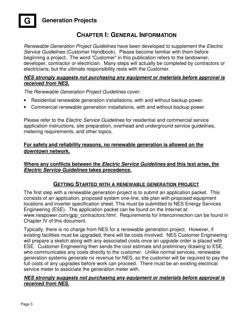
CHAPTER I: GENERAL INFORMATION
Renewable Generation Project Guidelines have been developed to supplement the Electric Service Guidelines (Customer Handbook). Please become familiar with them before beginning a project. The word “Customer” in this publication refers to the landowner, developer, contractor or electrician. Many steps will actually be completed by contractors or electricians, but the ultimate responsibility rests with the Customer.
NES strongly suggests not purchasing any equipment or materials before approval is received from NES.
The Renewable Generation Project Guidelines cover:
• Residential renewable generation installations, with and without backup power.
• Commercial renewable generation installations, with and without backup power.
Please refer to the Electric Service Guidelines for residential and commercial service application instructions, site preparation, overhead and underground service guidelines, metering requirements, and other topics.
For safety and reliability reasons, no renewable generation is allowed on the
downtown network.
Where any conflicts between the Electric Service Guidelines and this text arise, the Electric Service Guidelines takes precedence.
GETTING STARTED WITH A RENEWABLE GENERATION PROJECT
The first step with a renewable generation project is to submit an application packet. This consists of an application, proposed system one-line, site plan with proposed equipment locations and inverter specification sheet. This must be submitted to NES Energy Services Engineering (ESE). The application packet can be found on the Internet at: www.nespower.com/gpp_contractors.html. Requirements for Interconnection can be found in Chapter IV of this document.
Typically, there is no charge from NES for a renewable generation project. However, if existing facilities must be upgraded, there will be costs involved. NES Customer Engineering will prepare a sketch along with any associated costs once an upgrade order is placed with ESE. Customer Engineering then sends the cost estimate and preliminary drawing to ESE, who communicates any costs directly to the customer. Unlike normal services, renewable generation systems generate no revenue for NES, so the customer will be required to pay the full costs of any upgrades before work can proceed. There must be an existing electrical service meter to associate the generation meter with.
NES strongly suggests not purchasing any equipment or materials before approval is received from NES.
G
Generation Projects
Page 4
SITE PLAN REQUIREMENTS
The following information is needed before NES can engineer the electrical layout:
• Location of existing meter.
• Location of proposed generation meter.
• Location of inverters.
• Site plans (digital copy preferred, hard copy is acceptable).
• Street name.
• Building envelopes shown on drawings.
• Easements on Final Plat (twenty feet (20’) adjacent to roads), if applicable.
• Indicate if service will be overhead or underground.
• Location of main electrical service panel/switchboard.
FREQUENTLY ASKED QUESTIONS
Question: When should I contact NES about my renewable generation project?
Answer: As early as possible, even before hiring an electrician or consultant. NES is happy to meet with you at your site to go over your plans or ideas.
Question: How long will my job take?
Answer: This depends on a lot of variables. Submitting a thorough and complete application packet (one-line, site plan, inverter specification sheet, and application) greatly speeds up the process. Notifying NES of your project as early as possible helps address potential roadblocks early on. Contract creation and approval also takes time. It may take eight to ten weeks or longer to get approval. Hard deadlines between contractors and customers should not be established. Payments should be made on “substantial completion” type language. Dates for final completion and commissioning are not under the control of the contractor or the customer.
Question: When should I purchase the equipment and materials for my project?
Answer: NES strongly recommends that you not purchase any project equipment or materials until you have received approval. This is to protect the Customer and Contractor from any undue financial burden caused by a project not being approved, or the wrong equipment being purchased.
Question: Why is the street address so important, and where do I get it?
Answer: The street address is used to match the NES order to the Codes release. Contact your county Codes official to obtain a valid street address.
Question: Will I need a release?
Answer: Yes, since new conductor is being added. Contact your local Codes department for a permit, inspection, and release.
G
Generation Projects
Page 5
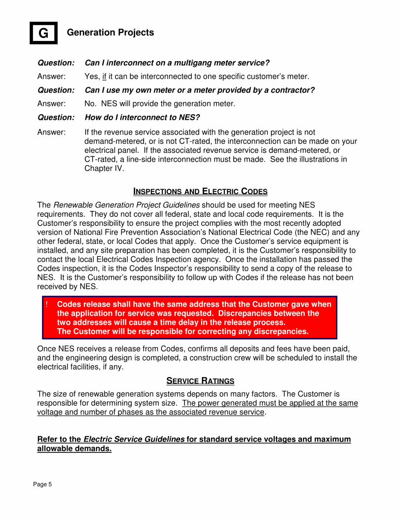
Question: Can I interconnect on a multigang meter service?
Answer: Yes, if it can be interconnected to one specific customer’s meter.
Question: Can I use my own meter or a meter provided by a contractor?
Answer: No. NES will provide the generation meter.
Question: How do I interconnect to NES?
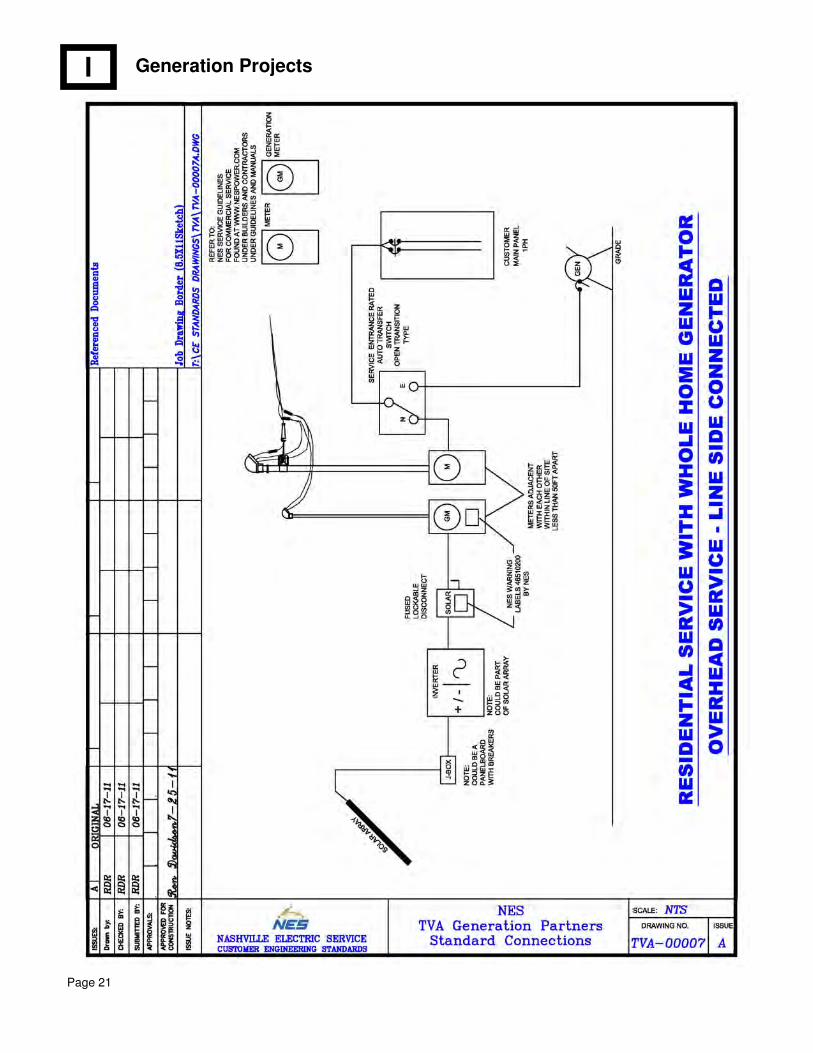
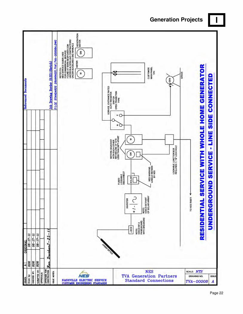
Answer: If the revenue service associated with the generation project is not demand-metered, or is not CT-rated, the interconnection can be made on your electrical panel. If the associated revenue service is demand-metered, or CT-rated, a line-side interconnection must be made. See the illustrations in Chapter IV.
INSPECTIONS AND ELECTRIC CODES
The Renewable Generation Project Guidelines should be used for meeting NES requirements. They do not cover all federal, state and local code requirements. It is the Customer’s responsibility to ensure the project complies with the most recently adopted version of National Fire Prevention Association’s National Electrical Code (the NEC) and any other federal, state, or local Codes that apply. Once the Customer’s service equipment is installed, and any site preparation has been completed, it is the Customer’s responsibility to contact the local Electrical Codes Inspection agency. Once the installation has passed the Codes inspection, it is the Codes Inspector’s responsibility to send a copy of the release to NES. It is the Customer’s responsibility to follow up with Codes if the release has not been received by NES.
Once NES receives a release from Codes, confirms all deposits and fees have been paid, and the engineering design is completed, a construction crew will be scheduled to install the electrical facilities, if any.
SERVICE RATINGS
The size of renewable generation systems depends on many factors. The Customer is responsible for determining system size. The power generated must be applied at the same voltage and number of phases as the associated revenue service.
Refer to the Electric Service Guidelines for standard service voltages and maximum allowable demands.
G
! Codes release shall have the same address that the Customer gave when the application for service was requested. Discrepancies between the two addresses will cause a time delay in the release process. The Customer will be responsible for correcting any discrepancies.
Generation Projects
Page 6
A
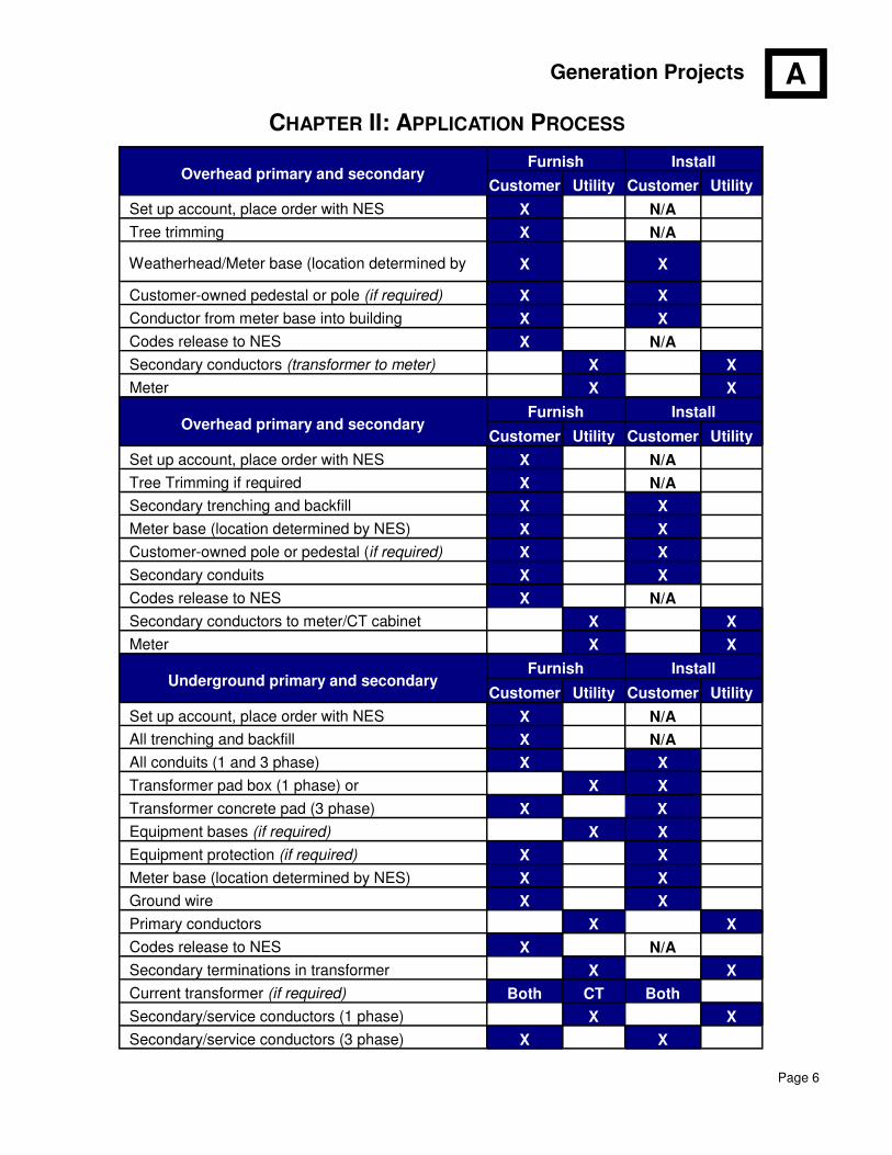
CHAPTER II: APPLICATION PROCESS
Overhead primary and secondary Furnish Install
Customer Utility Customer Utility
Set up account, place order with NES X N/A
Tree trimming X N/A
Weatherhead/Meter base (location determined by X X
Customer-owned pedestal or pole (if required) X X
Conductor from meter base into building X X
Codes release to NES X N/A
Secondary conductors (transformer to meter) X X
Meter X X
Overhead primary and secondary Furnish Install
Customer Utility Customer Utility
Set up account, place order with NES X N/A
Tree Trimming if required X N/A
Secondary trenching and backfill X X
Meter base (location determined by NES) X X
Customer-owned pole or pedestal (if required) X X
Secondary conduits X X
Codes release to NES X N/A
Secondary conductors to meter/CT cabinet X X
Meter X X
Underground primary and secondary Furnish Install
Customer Utility Customer Utility
Set up account, place order with NES X N/A
All trenching and backfill X N/A
All conduits (1 and 3 phase) X X
Transformer pad box (1 phase) or X X
Transformer concrete pad (3 phase) X X
Equipment bases (if required) X X
Equipment protection (if required) X X
Meter base (location determined by NES) X X
Ground wire X X
Primary conductors X X
Codes release to NES X N/A
Secondary terminations in transformer X X
Current transformer (if required) Both CT Both
Secondary/service conductors (1 phase) X X
Secondary/service conductors (3 phase) X X
Generation Projects
Page 7
A
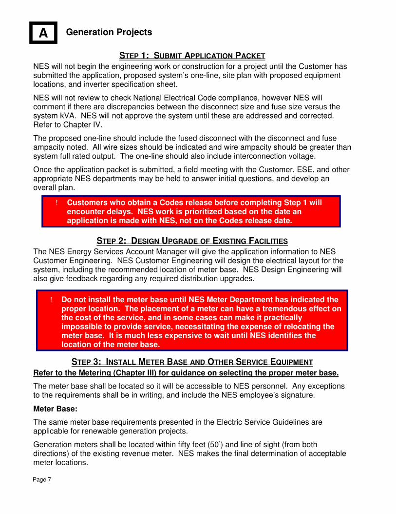
! Customers who obtain a Codes release before completing Step 1 will encounter delays. NES work is prioritized based on the date an application is made with NES, not on the Codes release date.
STEP 1: SUBMIT APPLICATION PACKET
NES will not begin the engineering work or construction for a project until the Customer has submitted the application, proposed system’s one-line, site plan with proposed equipment locations, and inverter specification sheet.
NES will not review to check National Electrical Code compliance, however NES will comment if there are discrepancies between the disconnect size and fuse size versus the system kVA. NES will not approve the system until these are addressed and corrected. Refer to Chapter IV.
The proposed one-line should include the fused disconnect with the disconnect and fuse ampacity noted. All wire sizes should be indicated and wire ampacity should be greater than system full rated output. The one-line should also include interconnection voltage.
Once the application packet is submitted, a field meeting with the Customer, ESE, and other appropriate NES departments may be held to answer initial questions, and develop an overall plan.
STEP 2: DESIGN UPGRADE OF EXISTING FACILITIES The NES Energy Services Account Manager will give the application information to NES Customer Engineering. NES Customer Engineering will design the electrical layout for the system, including the recommended location of meter base. NES Design Engineering will also give feedback regarding any required distribution upgrades.
STEP 3: INSTALL METER BASE AND OTHER SERVICE EQUIPMENT
Refer to the Metering (Chapter III) for guidance on selecting the proper meter base.
The meter base shall be located so it will be accessible to NES personnel. Any exceptions to the requirements shall be in writing, and include the NES employee’s signature.
Meter Base:
The same meter base requirements presented in the Electric Service Guidelines are applicable for renewable generation projects.
Generation meters shall be located within fifty feet (50’) and line of sight (from both directions) of the existing revenue meter. NES makes the final determination of acceptable meter locations.
! Do not install the meter base until NES Meter Department has indicated the proper location. The placement of a meter can have a tremendous effect on the cost of the service, and in some cases can make it practically impossible to provide service, necessitating the expense of relocating the meter base. It is much less expensive to wait until NES identifies the location of the meter base.

Generation Projects
Page 8
A
Figure 1: Generation Service Mast Installation
Drawing Notes:
1. NES will not connect service wire to attachment hardware deemed unsafe, such as screw in knobs.
2. Communication lines shall not attach to the electric service mast.
3. NES may require a guy wire opposing the wire tension depending on the wire size and length. If a guy wire is required by NES, it shall have a rated tensile strength of at least 2,500 pounds. Codes may also require a guy depending on the service mast height. If Codes requires a guy, the specifications for the guy wire will need to be provided by local Codes.
4. Minimum vertical clearance from service conductor to roof shall be eighteen inches (18”) within a six-foot (6’) radius of the service mast, and three and one half feet (3.5’) outside of the six-feet (6’) radius. Roofs that are readily accessible to pedestrian traffic shall have a minimum of ten feet (10’) of vertical clearance.
5. Service mast shall meet all NEC and local codes. Check with local Codes inspector for complete list of Code requirements.
6. Required conductor clearances are eighteen feet (18’) over roads, sixteen feet (16’) over a driveway. For lines crossing land that will not be subject to traffic of any kind (including vehicles, trucks, and horseback riders), the absolute minimum clearance is twelve feet (12’).
7. Point of delivery shall be less than twenty-two feet (22’) above final grade unless truck access is available. However, clearance issues overrule this requirements.
Generation Projects
Page 9
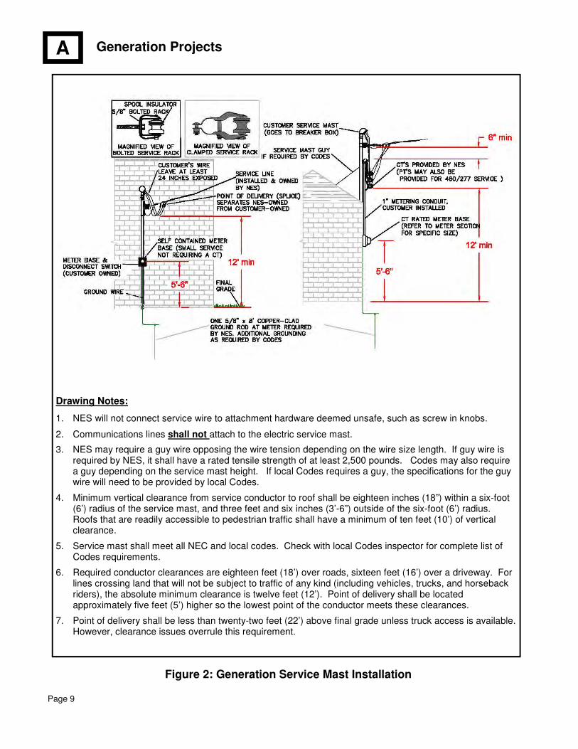
Drawing Notes:
1. NES will not connect service wire to attachment hardware deemed unsafe, such as screw in knobs.
2. Communications lines shall not attach to the electric service mast.
3. NES may require a guy wire opposing the wire tension depending on the wire size length. If guy wire is required by NES, it shall have a rated tensile strength of at least 2,500 pounds. Codes may also require a guy depending on the service mast height. If local Codes requires a guy, the specifications for the guy wire will need to be provided by local Codes.
4. Minimum vertical clearance from service conductor to roof shall be eighteen inches (18”) within a six-foot (6’) radius of the service mast, and three feet and six inches (3’-6”) outside of the six-foot (6’) radius. Roofs that are readily accessible to pedestrian traffic shall have a minimum of ten feet (10’) of vertical clearance.
5. Service mast shall meet all NEC and local codes. Check with local Codes inspector for complete list of Codes requirements.
6. Required conductor clearances are eighteen feet (18’) over roads, sixteen feet (16’) over a driveway. For lines crossing land that will not be subject to traffic of any kind (including vehicles, trucks, and horseback riders), the absolute minimum clearance is twelve feet (12’). Point of delivery shall be located approximately five feet (5’) higher so the lowest point of the conductor meets these clearances.
7. Point of delivery shall be less than twenty-two feet (22’) above final grade unless truck access is available. However, clearance issues overrule this requirement.
Figure 2: Generation Service Mast Installation
A
Generation Projects
Page 10
M
See the Electric Service Guidelines for Metering Requirements.
Note that if a renewable generation system is over 200A, a CT-rated meter will be required. You must purchase the CT’s and PT’s from NES for renewable generation projects.
If the nameplate capacity of the renewable generation system is over 10 kW, an interval meter must be ordered. Commissioning of systems over 10 kW may be delayed dependent upon receipt of interval meter from our vendor.
Note that if a meter pedestal is used, it must be made from unistrut, unless special permission is granted in writing prior to construction. Wood is not acceptable for meter pedestals.
NES must approve all generation meter locations. If a customer moves meter equipment post commissioning, NES must approve the new location.
The distance between a renewable disconnect and the generation meter must allow for an NES hasp lock. NES reserves the right to require disconnects and meters to be adequately spaced. See the Electric Service Guidelines for these clearance requirements.
Renovations/Additions
If a meter is made inaccessible after installation (for example, if a sunroom is built next to the wall with the meter base), the Customer will bear the cost for moving the metering facilities to an accessible outside location approved by NES Engineering.
Refer to Customer Handbook for underground customer meter pedestal requirements, and for overhead customer meter pole requirements.
CHAPTER III: METERING
! All NES approved meter bases can be found at www.nespower.com under the “Builders & Contractors” tab. Contact the NES Meter Department (615-747-3805) with any metering concerns or questions.
Generation Projects
Page 11
M
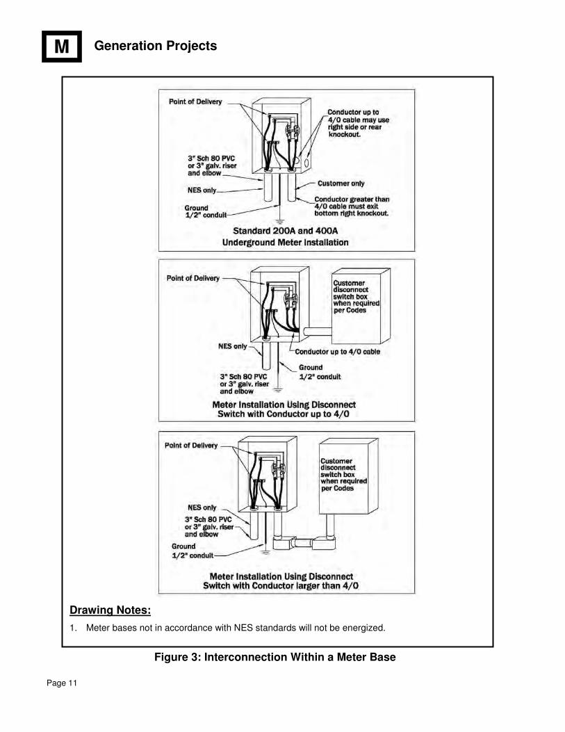
Drawing Notes:
1. Meter bases not in accordance with NES standards will not be energized.
Figure 3: Interconnection Within a Meter Base
Generation Projects
Page 12
M
19"
32"
28"
32"
15"
17"
Stainless steel
handle
with provision for
padlock
Mounting emboss for 38" lag boltFour (4) places
Front View End View
Bottom View
#14 - 2/0
CU-AL
Ground
Connector
18" drain hole
34"D x 26" H x
30" W
Grade BB
Plywood
17"
32"
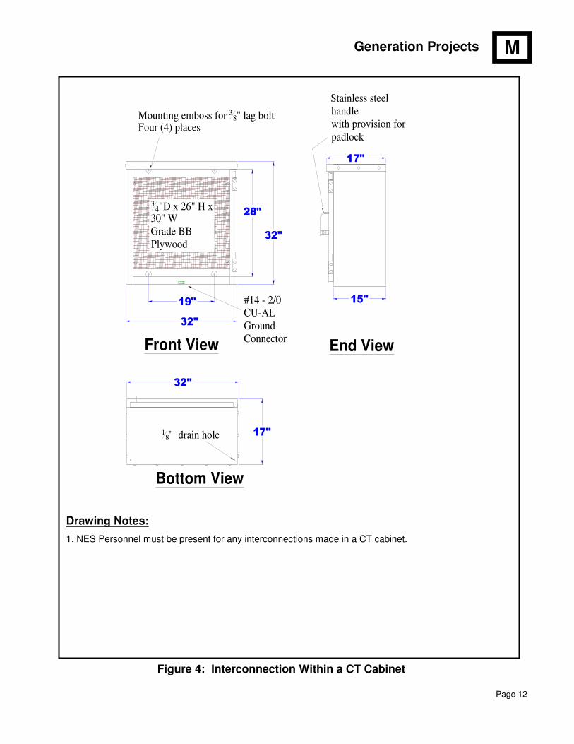
Drawing Notes:
1. NES Personnel must be present for any interconnections made in a CT cabinet.
Figure 4: Interconnection Within a CT Cabinet
Generation Projects
Page 13
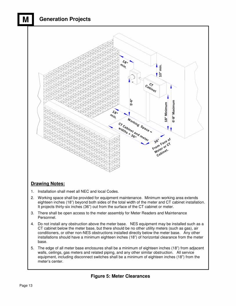
Drawing Notes:
1. Installation shall meet all NEC and local Codes.
2. Working space shall be provided for equipment maintenance. Minimum working area extends eighteen inches (18”) beyond both sides of the total width of the meter and CT cabinet installation. It projects thirty-six inches (36”) out from the surface of the CT cabinet or meter.
3. There shall be open access to the meter assembly for Meter Readers and Maintenance Personnel.
4. Do not install any obstruction above the meter base. NES equipment may be installed such as a CT cabinet below the meter base, but there should be no other utility meters (such as gas), air conditioners, or other non-NES obstructions installed directly below the meter base. Any other installations should have a minimum eighteen inches (18”) of horizontal clearance from the meter base.
5. The edge of all meter base enclosures shall be a minimum of eighteen inches (18”) from adjacent walls, ceilings, gas meters and related piping, and any other similar obstruction. All service equipment, including disconnect switches shall be a minimum of eighteen inches (18”) from the meter’s center.
M
Figure 5: Meter Clearances
widths + 36"
CTCabinet
18" M
inim
um
10" m
in.
5'-6
"
CT Cabinet and meter
Cabinet.Meter o
r CT
From Face
of
min.
18"
min.
18"
Space =
Working
36"
6'-8
" M
axi
mum
Generation Projects
Page 14
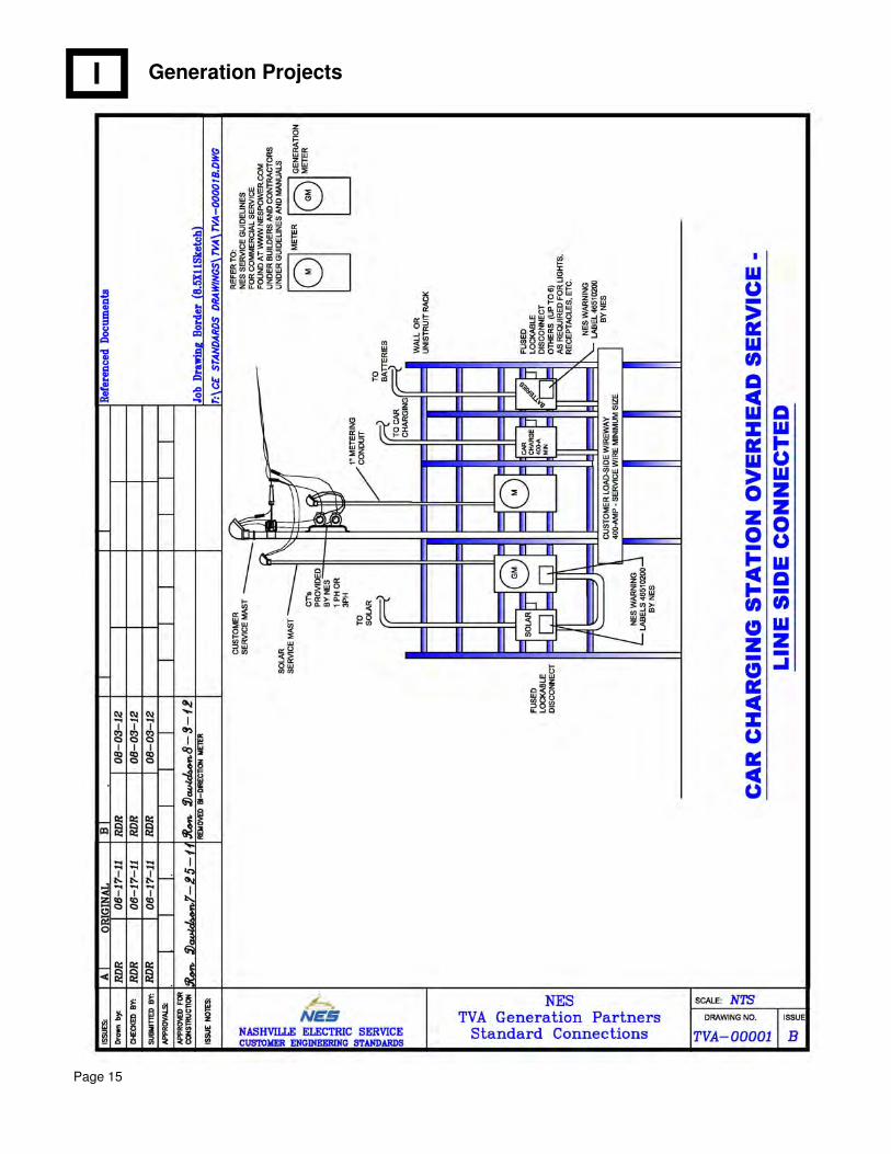
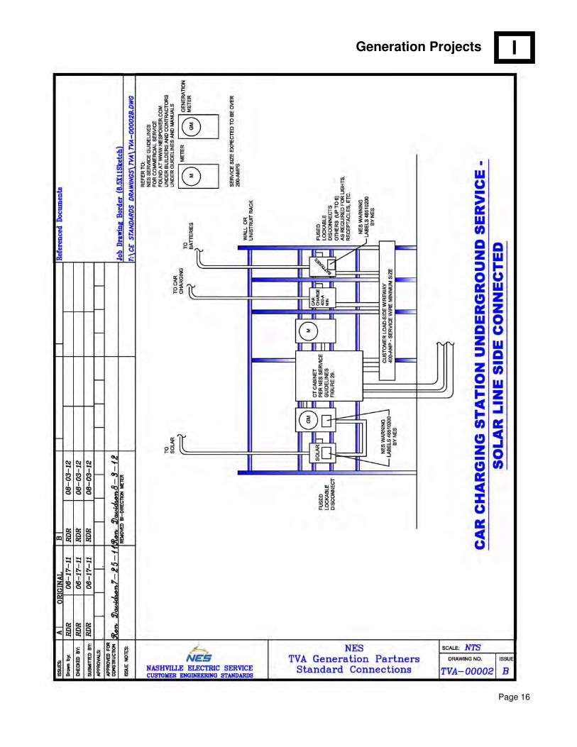
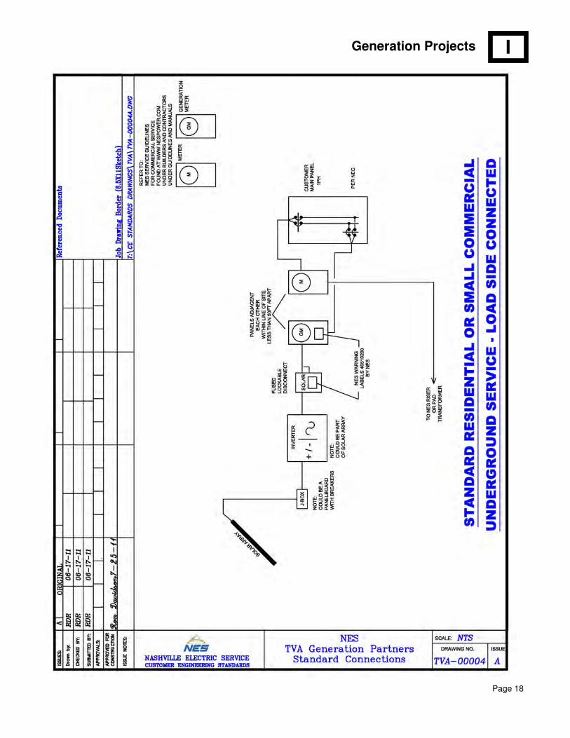
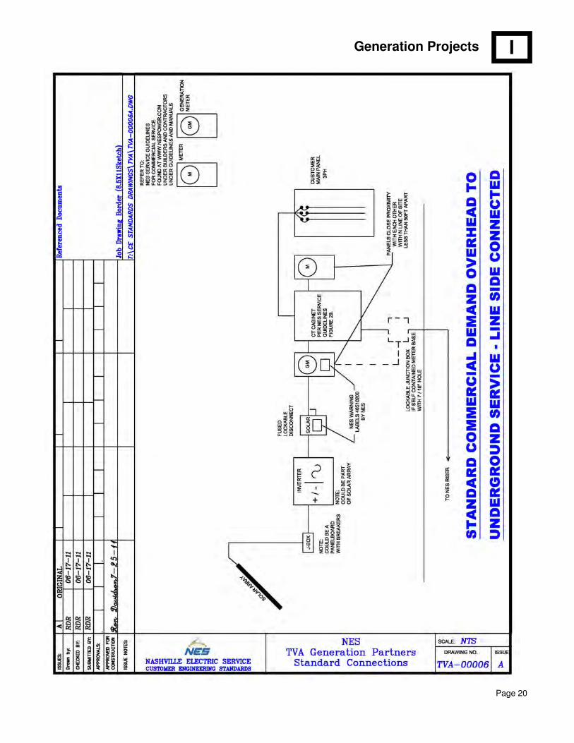
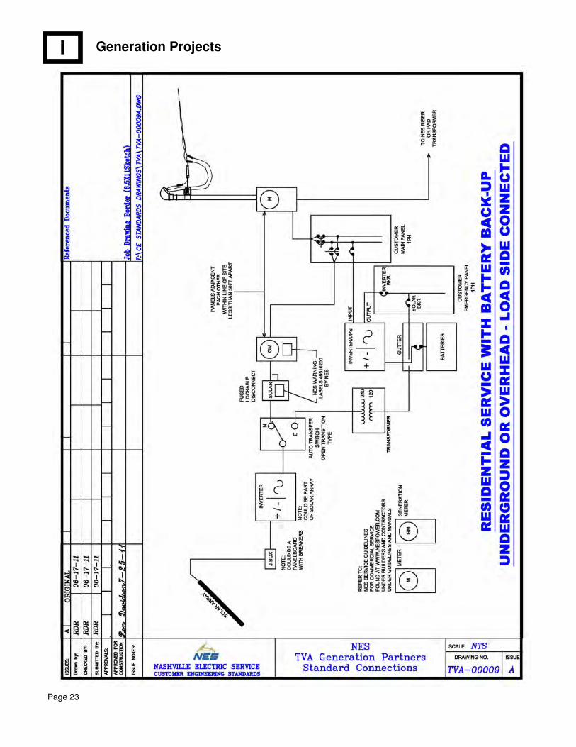
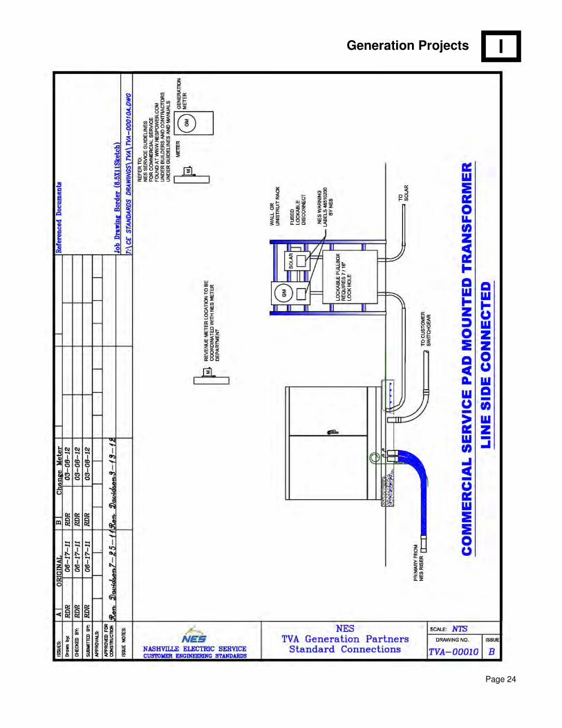
This section contains sample one-line diagrams for different system configurations. NES strongly urges customers to use this format in their designs. In addition to the basic drawing elements, make note of the following:
1. Wire size and fuse size shall be included. NES will not specify wire or fuse sizes for the customer.
2. Wire size should be at least the same ampacity as the fuse, and should be greater than the fully rated output of the system.
3. The number of inverters and combiners shall be shown.
4. The system voltage should be indicated.
A renewable generation system must interconnect at the same voltage that NES delivers to the customer’s revenue meter. If the revenue service is primary metered, the system must deliver primary voltage back.
NES may reject a single phase battery system on a three phase system that places a large imbalance on the feeding transformer.
I
CHAPTER IV: INTERCONNECTION
Generation Projects
Page 15
I
Generation Projects
Page 16
I

Generation Projects
Page 17
I
Generation Projects
Page 18
I

Generation Projects
Page 19
I
Generation Projects
Page 20
I
Generation Projects
Page 21
I
Generation Projects
Page 22
I
Generation Projects
Page 23
I
Generation Projects
Page 24
I

Generation Projects
Page 25
I