Renewable energy grid integration
141
Renewable Energy Grid Integration Raquel Garde PhD Granada, April 26, 2016
-
Upload
rcreee -
Category
Data & Analytics
-
view
382 -
download
0
Transcript of Renewable energy grid integration

Renewable Energy Grid Integration
Raquel Garde PhD
Granada, April 26, 2016

s u m m a r y
1. Renewable energies context in Spain 2. Impact of RE in the system3. System Operation 4. Smart Grids5. Energy Storage6. Regulatory & Market Framework

1. Renewable energies context in Spain

1. Renewable energies context in Spain
• Target 20-20-20 for 2020:• 20% of improvement in energy efficiency• 20% of reduction of greenhouse emissions• 20% of the final gross energy consumption must be supplied by renewable energy
• New Spanish plan for 2011-2020:• Design of new energy scenarios• Set the objectives for Spain to be consistent with the 2009/28/CE Directive from
European Parliament• Binding minimal target for every member state and EU as a whole
• Minimum share of renewable energy of 20% in the final gross consumption of energy
• Minimum share of renewable energy of 10% in the energy consumption from transport

1. Renewable energies context in Spain

1. Renewable energies context in Spain
Source: REE

1. Renewable energies context in Spain

1. Renewable energies context in Spain
1. Renewable energies context in Spain
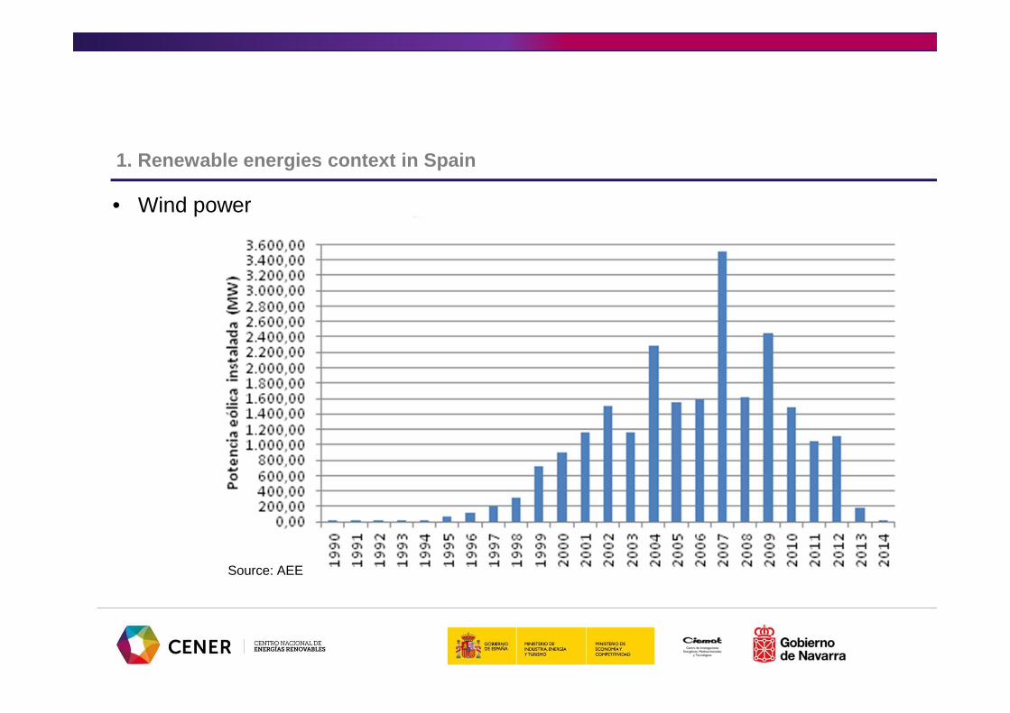
• Wind power
Source: AEE

1. Renewable energies context in Spain
• Wind power
Wind generation and variation rate in 2012

1. Renewable energies context in Spain
• Solar energy-PV
Evolution of the power capacity installed per year and accumulated (period 2007-2013). Source: UNEF

1. Renewable energies context in Spain
• Solar thermal energy
Evolution of installed Concentrated Solar Power cap acity (left axis) and electricity generation (right axis) (2007-2014)

1. Renewable energies context in Spain
• Biofuels
Penetration of biofuels in Spain in terms of energy content. Source: APPA.

1. Renewable energies context in Spain
• Renewable thermal (biomass)
The evolution of the accumulated capacity (left) an d the electricity sold (right) in the Biomass Secto r

1. Renewable energies context in Spain
• Small Hydro Power
Evolution of the accumulated capacity (left) and el ectricity generation (right) of Small Hydro Power ( period 2005-2014)

1. Renewable energies context in Spain
• Spain expects RES to contribute to the total energy with the 22.7% and 42.3% to the electric energy in 2020.
• 35 GW of wind power, 16.6 GW of hydraulic energy and 7 GW of photovoltaic energy

1. Renewable energies context in Spain
• Some key figures…
• Electricity consumption in Spain recovered in 2015 a positive rate of growth not seen since 2010
• In 2015 CO2 emissions of the electricity sector rise as a result of the increase in coal-fired generation
• The percentage over total from renewables in demand coverage was 37.4% in 2015

2. Impact of RE in the system

2. Impact of RE in the system
• The share of renewable energy in the Spanish mix has increased over the years significantly and is supposed to increase even more. Therefore it is paramount to know:
• Which are the issues and problems renewable energy poses to the power system
• Which are the means to overcome these problems
• Which are the regulatory measures adopted and if they are suitable or not
Main issues to consider:• New and in-depth focus on system planning . Steady-state and dynamic considerations
are crucial.• Accurate resource and load forecasting becomes highly valuable and important.• Voltage support . Managing reactive power compensation is critical to grid stability. This
also• includes dynamic reactive power requirements of intermittent resources.• Evolving operating and power balancing requirements . Sensitivity to existing generator
ramp rates to balance large scale RES generation, providing regulation and minimizing start-stop operations for load following generators.
• Increased requirements on ancillary services . Faster ramp rates and a larger percentage of
• regulation services will be required which can be supplied by responsive storage facilities.• Equipment selection . Variable Speed Generation (VSG) turbines and advanced solar
inverters have the added advantage of independent regulation of active and reactive power. • Strong interconnections and large storage systems . Larger regional control areas make
balancing possible.
2. Impact of RE in the system

• Grid stability : • When RES share is high, sudden and large loss of power generation can
happen due to different causes:• Weather changes (wind and sun availability) • Some old wind turbine technologies disconnected from the grid when facing
voltage dips• It must be balanced by using additional generation as support or by international
exchanges• Because conventional generation does not react as quickly as RES typically
does, the grid operator on the transmission network has to deal with rapid changes in voltage on the grid.
• The balance between generation and demand is jeopardized, putting in risk the stability of the grid
2. Impact of RE in the system
• Grid operation:• Variable renewable energy depends on the resources availability• Manageable generation (conventional and renewable) is needed for
“security of supply” purposes• The intermittency of RES has an impact on:
• The scheduling of the generation• The market operation as new ancillary services are needed
• To smooth these effects it is necessary to have renewable resources forecast as accurate as possible.
2. Impact of RE in the system

• Power quality:
• Availability of resources not always is close to consumption centres(mainly for large RES plants connected to the transmission network)
• Large transmission links introduce new issues with power quality and voltage management that can be solved with proper ancillary services
• But the suitable technology to provide them is not yet available
2. Impact of RE in the system

• Variability and intermittency of RES could potentially cause grid reliability issues related to reverse power flows .
• It happens when the amount of renewable power generated exceeds current consumption levels.
• Supply and demand have to be balanced at all times. If they are not, voltage and frequency fluctuations could disrupt or even destroy electronic equipment.
• New challenges are related to:
• system stability
• voltage quality & harmonics
• peak load management & congestion mitigation
• Distribution network
2. Impact of RE in the system

2. Impact of RE in the system
~ ~
~
~
Large centralised power generation (6 - 20kV)
Boost Transformer Station (132, 220, 400, 500, 700, … kV)Transmission Grid
> 132kV
Primary Distribution Network (132, 66, 45 kV)
Secondary Distribution Network (20, 15, 6.6 kV)
Substations HV
Substations HV/MV
Small consumers
Very large consumers
Large consumers
Medium consumers
Transformer Stations (220,380 V)
Small power generation plants
Small power generation plants

• The integration of the renewable energy in the power system must done in a safe way. It is necessary:
• To define the needed grid reinforcements
• To take into account the stability of the grid
• Forecasting ability
• To improve the observability and controllability:• Generator and System operator control• Management system
GRID DEVELOPMENT
ASSURING STABILITY
(Operational procedures)
ENHANCE DISPATCHABILITY
2. Impact of RE in the system

3. Methodology

• The methodology to integrate RES into the grid in a safe way should comprise several steps:
• Technical analysis of the Grid capacity by using specific software such as PSS/E, DigSilent, Apros, etc.
• Application of technical requirements defined in the network codes• Monitoring and control of the system by the System Operator (SO)• Economical analysis of energy scenarios with specific software
such as TIMES, PRIMES, Plexos, etc.
3. Methodology

•Red Eléctrica de España is the Spanish TSO
•It manages the operation in real time to match generation and demand
•Management is based on forecasts
•Responsible of drawing up the transmission grid development plans, approved by the Ministry of Industry, Tourism and Trade.
•REE handles the so-called adjustment services as well
3. Methodology: Technical analysis/Grid development

• A good integration of RES into the grid must consider (according REE-Spanish TSO) regarding Grid Development that:
• The decision about new transmission installations should include 2 coordinated process:
• Access to grid. It MUST BE regulated to evaluate the capacity. • Grid reinforcement planning is made by national and regional
governments
• Development of transmission lines
3. Methodology: Technical analysis/Grid development

• GRID CAPACITY STUDIES• Evaluation of the generation limits to maintain sustainability and security of
the system according the planning and operation criteria
• SUSTAINABILITY. Capacity studies to define the generation limits in each node and zone
• Static behavior: power flow and contingencies analysis• Short-circuit: 5% Scc
• SECURITY• Dynamic analysis: behavior of grid after a short-circuit
• DESIGN CRITERIA OF GRID
3. Methodology: Technical analysis/Grid development
� The Siemens PTI PSS®E simulator is a software tool that is composed of acomprehensive set of programs for studies of power system transmission network andgeneration performance in both steady-state and dynamic conditions.
� It facilitates calculations for a variety of analyses:� Power Flow� Optimal Power Flow� Balanced & Unbalanced faults� Dynamic Simulation
� It presents 2 power simulators, one for static analysis and the other one for dynamicanalysis• Power flow analysis• Voltage and overvoltage analysis• Contingency analysis (N-1).• Fault analysis (balance and unbalance)• Dynamic analysis (generation and load loss, triggered lines, short-circuits, …)
3. Methodology: Technical analysis/Grid development

� N-1 are related to all elements are in service except one that it is out� It considers the loss of transmission lines. It analyzes the overloads and the
voltages out of range in each node
Static Analysis: Contingency N-1
Static Analysis: Short-circuit
� REE procedure includes a shortcircuit study to analysis the capability ofthe grid
Dynamic Analysis
� Dynamic models: PSS/E library has dynamic models for generators� Three-phase short-circuit to analyse the behavior of the grid during this
fault and the stability recovery
3. Methodology: Technical analysis/Grid development

Infrastructure Development Plans
•REE is responsible for developing and extending the grid, for maintaining it and managing the transmission of electricity between external systems and the peninsula
•41,200 km of high voltage electricity lines, more than 5,000 substation bays, and more than 78,000 MVA of transformer capacity
•International interconnections <3% with France (electrical island)
•Strategic Plan 2011-2015: reinforcements of Spain-France connection, Peninsula-Baleares Islands and Ibiza-Mallorca
3. Methodology: Technical analysis/Grid development

3. Methodology: Technical analysis/Grid development

•Throughout the grid capacity analysis it is possible to:
• Identify grid reinforcement and new investments needs
• Define Infrastructure Development Plans
• Establish connection priorities and identify most suitable connection emplacements (nodes)
• Identify congestion points
• Achieve RES integration goals
3. Methodology: Technical analysis/Grid development

• Network codes or operational procedures are approved by the Ministry with consultation to the CNE.
• Some of the Operational Procedures (PO) apply also to RES units:• PO 3.2. Technical constraint management (D-1, real-time...)• PO 8.2. System operation of generation and transmission• PO 9 Information exchanged with the System Operator (observability)
• Some are specific for RES generation:• RD 661/2007 Voltage control aspects• PO 3.7 Controllability of non-manageable RES generation• PO 12.3 Voltage dip ride-through capabilities of wind generation• PO 12.2 Requirements for new generators.
• At draft stage:• PO 7.5 Voltage control by RES.
3. Methodology: Assuring Stability/Operational Proced ures
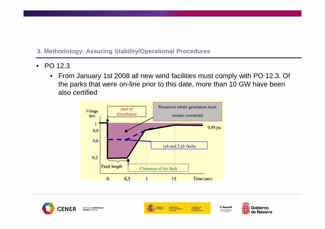
• PO 12.3• From January 1st 2008 all new wind facilities must comply with PO 12.3. Of
the parks that were on-line prior to this date, more than 10 GW have been also certified
3. Methodology: Assuring Stability/Operational Proced ures

• RD 661/2007 Art. 29: Reactive power bonus or penalization.
• From +8 to -4% of 7.8441 c€/kWh depending on the power factor.
• Periods do not distinguish between labor days or holidays so producers might behave contrary to system requirements.
• In reality it leads to simultaneous connection/disconnection of capacitors.
• SO may issue instructions to modify these table values for plants larger than 10 MW if voltage problems are detected. This is done regularly
3. Methodology: Assuring Stability/Operational Proced ures

• PO12.2 and PO 7.5 (Pending Approval) impose New Requirements: Specific requirements for plants connected synchronously or with power electronics.
• P>10 MW• The installation must remain connected and
certain amount of time according to the following voltage vs frequency zones
• The installation must not be disconnected• Neither by the action of the minimum
voltage protection • Nor due to the failure of automation and
control equipment during voltage dips with residual tension lower than 0,85 pu with a duration of less than 1 sg
• The installation must not be disconnected facing deviate of frequency ±2Hz/sg
3. Methodology: Assuring Stability/Operational Proced ures

• Overvoltage requirements• Voltage control requirements:
• Installation must have the ability • To perform a set-point voltage control
with the capacity of real time set-point changes
• To perform a reactive power control • Delivery of reactive power will be made
through and Automatic Voltage Regulator• 0,95≤V≤1,05 pu installation: ability to
deliver/absorb reactive power in a minimum range to collaborate in the maintenance of the voltage
3. Methodology: Assuring Stability/Operational Proced ures

• Voltage dip• The profile may change depending on the kind of short-circuit
3. Methodology: Assuring Stability/Operational Proced ures

• Other requirements• Possibility of providing frequency
control• Disturbed regime voltage control• Inertia emulation• Oscillation damping
• New Operational Procedures will be developed or updated to use these future capacities.
3. Methodology: Assuring Stability/Operational Proced ures
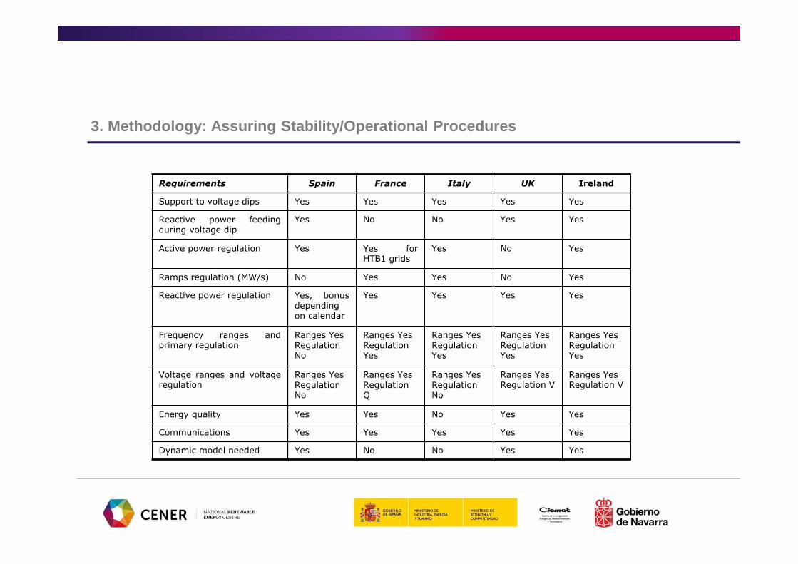
Requirements Spain France Italy UK Ireland
Support to voltage dips Yes Yes Yes Yes Yes
Reactive power feedingduring voltage dip
Yes No No Yes Yes
Active power regulation Yes Yes forHTB1 grids
Yes No Yes
Ramps regulation (MW/s) No Yes Yes No Yes
Reactive power regulation Yes, bonusdependingon calendar
Yes Yes Yes Yes
Frequency ranges andprimary regulation
Ranges YesRegulationNo
Ranges YesRegulationYes
Ranges YesRegulationYes
Ranges YesRegulationYes
Ranges YesRegulationYes
Voltage ranges and voltageregulation
Ranges YesRegulationNo
Ranges YesRegulationQ
Ranges YesRegulationNo
Ranges YesRegulation V
Ranges YesRegulation V
Energy quality Yes Yes No Yes Yes
Communications Yes Yes Yes Yes Yes
Dynamic model needed Yes No No Yes Yes
3. Methodology: Assuring Stability/Operational Proced ures

Requirements Poland Romania USA Germany Scandinavia
Support to voltage dips Yes Yes Yes, but notspecified
Yes Yes
Reactive power feedingduring voltage dip
Yes No No Yes No
Active power regulation Yes Yes No Yes Yes
Ramps regulation (MW/s) Yes Yes No Yes Yes
Reactive power regulation Yes Yes Yes Yes Yes
Frequency ranges andprimary regulation
Ranges YesRegulationYes
Ranges YesRegulationYes
Ranges NoRegulationNo
Ranges YesRegulationYes
Ranges YesRegulation Yes
Voltage ranges and voltageregulation
Ranges YesRegulation Qo V
Ranges YesRegulationNo
Ranges NoRegulationNo
Ranges YesRegulation Q
Ranges YesRegulation Q
Energy quality Yes Yes No Yes Yes
Communications Yes Yes Yes Yes Yes
Dynamic model needed Yes Yes No No Yes
3. Methodology: Assuring Stability/Operational Proced ures

•REE requires real-time communication with the generating stations
•By CECRE control centre of renewable energies
•Integrated in the main Power Control Centre CECOEL
3. Methodology: Enhancing Dispatchability

• WHY A CONTROL CENTER FOR RENEWABLE ENERGIES?
• Renewable energies unlike conventional ones are difficult to operate. Therefore, a control center improves:
• Profitability• Operation• Integration in the process
• Moreover it contributes to solve some of the issues inherent to Renewable Sources:
• Deviations• Regulation difficulties• Resource Variability
3. Methodology: Enhancing Dispatchability

• SPECIAL CHARACTERISTICS OF A CONTROL CENTER FOR RENEWABLE ENERGIES
• Relatively low generation per plant and geographical dispersion• Unlike the conventional generation• Complex communication
• Many different technologies• High amount of data
• Wind turbine: 300 variables/MW approx.• Thermal plant : up to 30 variables/MW with an average of 10
variables/MW• A medium-high owner with 500 MW must be able to handle 150.000
points in real time. Complex SCADAS.
3. Methodology: Enhancing Dispatchability
• REE published a procedure with the minimum requirements to the Generation Control Centers (CCG) imposed by the CECRE
• Requirements for CCGs :• Communication CCG – CECRE:
• CCG sends in real time (12 s) at least the following information from each group of generators (in case of wind energy by wind farm)
• Active Power• Reactive Power• State of the connection with transmission or distribution grid• Voltage measurement
• Additionally for wind farms it will be send:• Wind speed (intensity and direction)• Temperature
3. Methodology: Enhancing Dispatchability

• Requirements for CCGs:• Communication CCG – CECRE:
• CCG must:• Capture the information of each generator that will be sent to
CECRE• Assure the data logic
• CECRE sends the set points to the generators• For wind energy, CCG receives, with a minimum period of 1 minute, the
set points of power for each node and type of RES plant calculated by CECRE. This production must be reached in maximum time of 15 minutes
• To assure the fulfillment of the set points for each CCG, the SO admits deviations higher than 10% of the set point for a time less than 5 minutes.
3. Methodology: Enhancing Dispatchability

• Requirements for CCGs:• CCG must be connected through broadband communication lines to assure
the data exchange ratio (typical minimum value 256 kbps) • Technical and human resources to guarantee 24 hours x 365 days• It has a SCADA system 24x7 that will cover any equipment and/or
performance failure• The control system must assure that a problem in a critical function can be
solved in 1 hour maximum• The communication protocol will be ICCP (IEC-60870-6-503)
• According to RD661/2007 all special regime facilities >10 MW must be connected to a CCG.
• Plants with P > 1 MW must send via the distribution control center the real-time measurement of P
3. Methodology: Enhancing Dispatchability

3. Methodology: Economical analysis
• Economical analysis of energy scenarios in order to:
– Determine the feasibility of RES deployment plans
– Confirm the cost-effectiveness of the energy system configuration
• Developed with specific software:
– TIMES is an economical model generator of energy scenarios
– TIMES estimates the evolution of the energy system along the time and the penetration of new technologies (e.g. hydrogen, electric cars, solar energy, etc.)
– TIMES can be applied to the whole energy system or to specific sectors (e.g. electricity)
– TIMES studies the influence in the energy market of different parameters as incentives to new technologies, GHE penalties, environmental policies, natural resources costs, etc
3. Methodology: Economical analysis
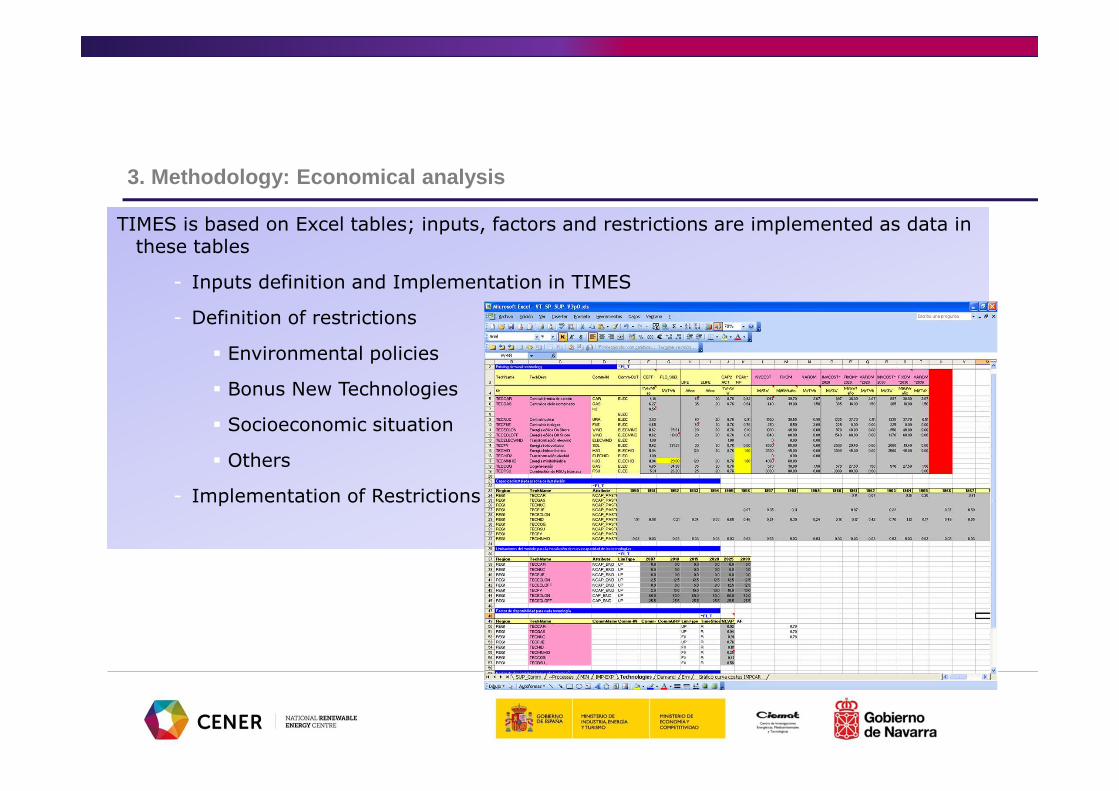
TIMES is based on Excel tables; inputs, factors and restrictions are implemented as data in these tables
- Inputs definition and Implementation in TIMES
- Definition of restrictions
� Environmental policies
� Bonus New Technologies
� Socioeconomic situation
� Others
- Implementation of Restrictions

3. Methodology: Economical analysis
- Analysis of sensibility
- Definition of factors
- Definition of scenarios
- Analysis of factors influence
Evolution of energy demand coverage by technology

3. Methodology: Economical analysis
- Results
- Generation mix (evolution of energy demand coverage by technology)
- Contribution of renewable energies and previsions (penetration capacity of new technologies)
- GHG reduction
- Imports reduction
Evolution of energy demand coverage by technology i n low, medium and high penetration of H2 scenarios

3. Methodology: Conclusions
• Renewable energies integration provokes some concerns and challenges in the grid operation
• A basic methodology to ensure a proper integration includes:
• Grid capacity studies and infrastructure planning• Networkcodes development• System Operator Controllability
• Additionally, economical analysis for diverse energy scenarios may be complementary
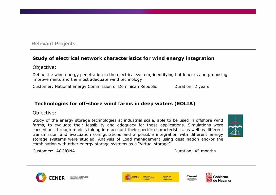
Study of electrical network characteristics for wind energy integration
Objective:
Define the wind energy penetration in the electrical system, identifying bottlenecks and proposing improvements and the most adequate wind technology
Customer: National Energy Commission of Dominican Republic Duration: 2 years
Relevant Projects
Technologies for off-shore wind farms in deep waters (EOLIA)
Objective:
Study of the energy storage technologies at industrial scale, able to be used in offshore windfarms, to evaluate their feasibility and adequacy for these applications. Simulations werecarried out through models taking into account their specific characteristics, as well as differenttransmission and evacuation configurations and a possible integration with different energystorage systems were studied. Analysis of Load management using desalination and/or thecombination with other energy storage systems as a “virtual storage”.
Customer: ACCIONA Duration: 45 months

Relevant Projects
CENIT SPHERA
Objective:
Strategic Industrial Research developed by a large industrial-public partnership related to the technical development of production, distribution, storage and use of hydrogen
Customer: ACCIONA ENERGIA Duration: 4 years
REVE (Management of Wind Power with Electric Vehicles )
Objective:
Detailed study of key technical and economical challenges to develop a network that facilitates electric vehicles to be used as energy storage systems and increase the integration of wind power into the electric grid
Partners: AEE, ENDESA, CIRCE Duration: 18 months
4. Smart Grids

4. Smart Grids
Source: “Gestión activa de la energía”, Agustín Escob ar, Siemens

4. Smart Grids
The SmartGrid is an electricity network that can intelligently integrate the actions of all users connected to it - generators, consumers and those that do both - in order to efficiently deliver sustainable, economic and secure electricity supplies. A smart grid employs innovative products and services together with intelligent monitoring, control, communication, and self-healing technologies in order to:
•Better facilitate the connection and operation of generators of all sizes and technologies;•Allow consumers to play a part in optimising the operation of the system;•Provide consumers with greater information and options for choice of supply;•Significantly reduce the environmental impact of the whole electricity supply system;•Maintain or even improve the existing high levels of system reliability, quality and security of supply;•Maintain and improve the existing services efficiently;•Foster market integration towards an European integrated market.

• The technologies gathered in the smart grid will accomplish the following goals:
• Make the grid more robust and optimized for improved operation and quality indices while minimizing electrical losses.
• Improve connection in areas with renewable resources, optimizing connection capacities and diminishing the cost of their connection
• Develop decentralized generating architectures that allow smaller power plants to work in a coordinated and cooperative manner with the power system.
• Improve integration of intermittent generation resources (renewable) and storage technologies.
• Further develop the power market, providing new functionalities and services to electricity market agents and final users
• Promote active management of demand so consumers become “prosumers”• Allow incorporation of the electric vehicle in the grid and its predictable large-scale
penetration
4. Smart Grids

• Global smart grid concept:• Smartly managed DERs• Prosumers• Smart meters• Inner smart grids:
• Virtual power plants• Microgrids• Cells
4. Smart Grids
• Smart Grid approaches:• Microgrids
• A low-voltage distribution system with distributed generation resources and storage devices. The microgrid may be operated either islanded or connected to the grid, and operation of its components can provide overall benefits to the system if they are managed and coordinated efficiently
• Virtual Power Plant• A Virtual Power Plant is a flexible representation of a portfolio of aggregated DERs. A VPP not
only clusters the capacity of many diverse DERs, but also creates a unique operating profile of the set of characteristics that define each DER and incorporates the spatial restrictions (e.g., of the power grid) in the description of its capacities in the portfolio
• Individual DERs can gain access and visibility on power markets.• System operation benefits from optimum use of the whole capacity available and increase
operating efficiency.
• Cell architecture• A distribution grid equipped with a controller which incorporates a communications network with
all of the distributed generation units and local users as well as the substation switching synchronization equipment connection between the distribution and transmission grids
• May be operated in isolated mode
4. Smart Grids

4. Smart Grids

• Smart Grid barriers• Technological maturity and “first mover” risk: Lack of standardized and mature
technologies• “Business case”:
• The investment and operational cost are still too high and • The expected benefits are hard to quantify and attribute to each agent.
• The regulatory bodies are not aware of the big role the smart grids could take to achieve the renewable boost, energy efficiency and CO2 reduction objectives and of the need to encourage the electrical infrastructure investment.
• Regulatory issues:• Technical barriers and limitations to the smart grid development• Inadequate incentive plan to encourage the investments.
• Access to funds: If the business model changes and the risks associated to regulated activity increase, the financial costs also increase making investments less profitable.
• Confidentiality and privacy of the data: The info available could potentially generate damages and problems if misused
4. Smart Grids

• The European Industrial Initiative on the electricity grid (SET-Plan)
• Enable the transmission and distribution of up to 35 % of electricity from dispersed and concentrated renewable sources by 2020 and make electricity production completely decarbonised by 2050.
• Further integrate national networks into a truly pan-European, market based network.
• Optimise the investments and operational costs involved in upgrading the European electricity networks to respond to the new challenges.
• Guarantee a high quality of electricity supply to all customers and engage them as active participants in energy efficiency.
• Anticipate new developments such as the electrification of transport
Smart meters interoperability is a MUST
4. Smart Grids

• Types of microgrids
• Voltage• AC microgrid• DC Microgrid• Mixed Microgrid
• Installation configuration• Centralized• Decentralized
• Operation mode• On-grid• Off-grid
4. Smart Grids: Microgrids
• Microgrid definition FP5 Project MICROGRIDS (ENK5-CT-2002-00610)
• Microgrids comprise Low Voltage distribution systems with distributed energy sources, storage devices and controllable loads, operated connected to the main power network or islanded, in a controlled, coordinated way.

Applications and Markets
• By 2020 the most important segment would correspond to the commercial and industry,
military and off-grid microgrids
• Microgrids market could grow up to $2.1 billion by 2015, with $7.8 billion invested over
that time
• Analysis of the Asia-Pacific Microgrid Market (Frost & Sullivan) estimates:
• market earned revenues of US$84.2 million in 2013
• this to reach US$814.3 million in 2020 at a compound annual growth rate (CAGR)
of 38.3 %.
3. Smart Grids: Microgrids

• Advantages:• Energy efficiency • Greenhouse emissions reduction• Increasing of the RES penetration• Increasing of the security of supply and
participation in the provision of ancillary services
• Reduction of electric losses
4. Smart Grids: Microgrids
Source: Navigant Research

4. Smart Grids: Microgrids

� A microgrid is smart grid� Generation, loads and storage systems management
� Microgrid Central Controller (MGCC) is the only interlocutor with the external grid:
� Inner balance between generation and demand� Effective coordination of all the devices to provide a
clear and aggregated response to the upstream grid
� The SO observes the microgrid as a controlled entity, a single aggregated load/generator
� Increasing of the penetration of RES. Manageability and observability improved.
� Microgrid concept allows a clear and transparent shift from the current model to bigger smart grids
� They can work as a building blocks of smart grids� Useful experiences and results
4. Smart Grids: Microgrids

� Functionalities during connected mode:� Forecasting� Economical dispatch� Emissions calculation
� MGCC receives inputs from:� Market prices� Energy sources bids� Demand side bids for low and high
priority loads
� MGCC sends the power setpoints to every device in the microgrid and the load shedding signals if needed
� Technical constraints imposed to the microgrid must be fulfilled and it must not disturb the upstream grid performance
� Increase generation � Disconnect generation
4. Smart Grids: Microgrids
•During connected mode the upstream grid provides voltage and frequency references to the microgrid devices

4. Smart Grids: Microgrids
• Isolated mode:• Generators must respond fast to load changes• Use of power electronic converters and no mechanical inertia• Some equipment have a slow response to setpoint changes• The use of storage systems is paramount to secure the initial energy
balance• Compensate the instantaneous unbalances between generation and
consumption• Provide voltage and frequency references to the rest of the elements• They are connected to the microgrid through a VSI controlled power
converter with adequate controls to keep the microgrid stable (voltage and frequency stability)

Sizing
Define equipments and installations
Define control strategies
Simulations
Define communication
protocols & protections
Implementation and final
validations
4. Smart Grids: Microgrids Deployment Methodology

Sizing
• Many parameters to take into account:
• Energy consumption profiles
• Natural resources availability
• Services to be provided
• Budget and economical feasibility
• Software to analyse and size the microgrid is needed
• HOMER
• HOGA/GRYSO
• WHG
• H2A
Microgrid Basic Configuration
4. Smart Grids: Microgrids Deployment Methodology

4. Smart Grids: Microgrids Deployment Methodology

Sizing
Define equipments and installations
Define control strategies
Simulations
Implementation and final
validations
Define communication
protocols & protections
4. Smart Grids: Microgrids Deployment Methodology

Define equipments and installations
• Defining scope of supply for equipment
• Technical requirements
• Auxiliaries
• Security needs
• Developing tenders
• Defining supporting infrastructures (electrical, venting, safety, water, etc.)
• Administrative and regulatory issues
Microgrid Draft Project
4. Smart Grids: Microgrids Deployment Methodology
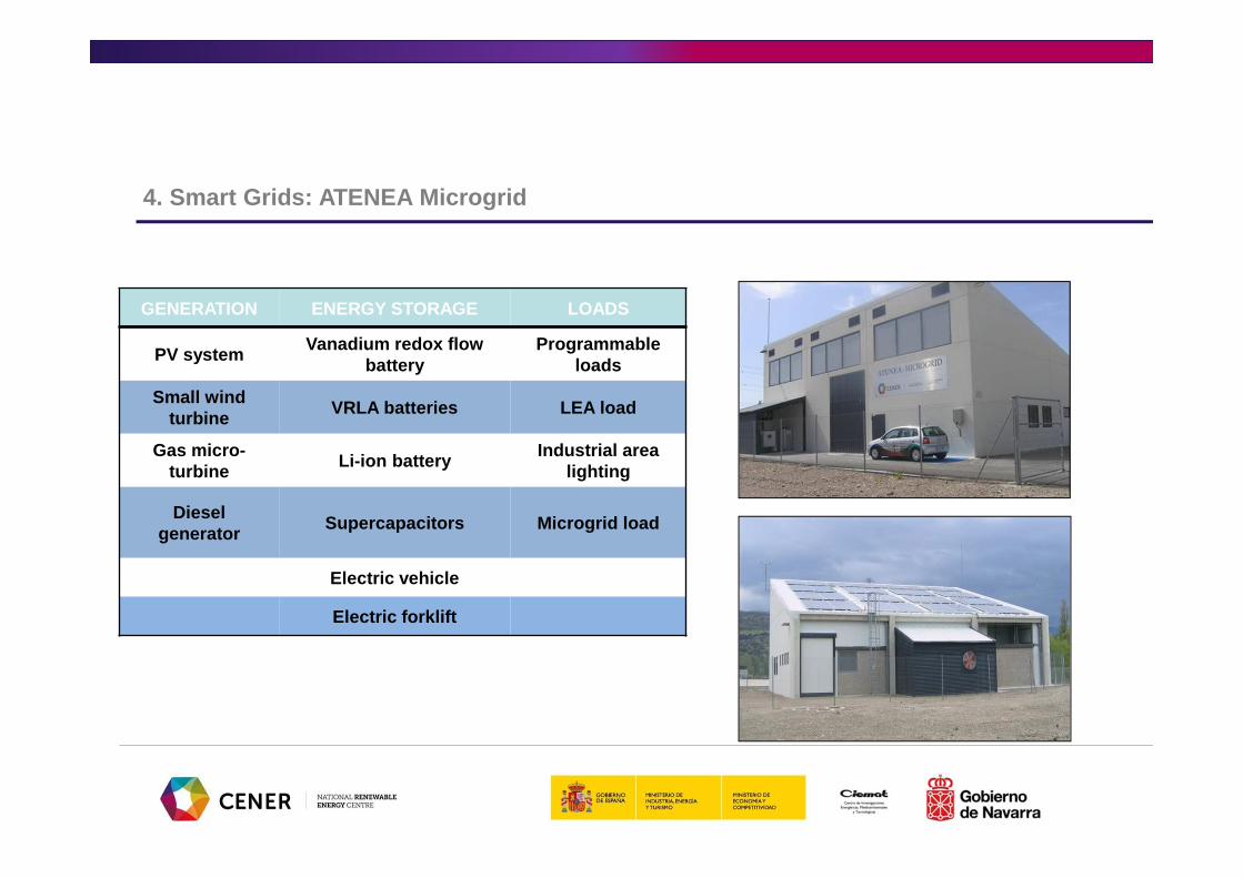
GENERATION ENERGY STORAGE LOADS
PV systemVanadium redox flow
batteryProgrammable
loads
Small wind turbine
VRLA batteries LEA load
Gas micro-turbine
Li-ion batteryIndustrial area
lighting
Diesel generator
Supercapacitors Microgrid load
Electric vehicle
Electric forklift
4. Smart Grids: ATENEA Microgrid

GENERATION
G- Photovoltaic Installation 25 kWp
G- Wind turbine 20 kW full-converter
G- Diesel Generator 55 kVA and gas microturbine 30 kW (CHP-
trigeneration)
4. Smart Grids: ATENEA Microgrid

STORAGE SYSTEMS
S- Lead Acid Batteries, 50 kW x 2 hours S- Redox Battery 50 kW x 4 hours
4. Smart Grids: ATENEA Microgrid

S- Lithium Ion, 50 kW x 1/2 hour S- Supercapacitors 30 kW, 4 sg
STORAGE SYSTEMS
4. Smart Grids: ATENEA Microgrid

LOAD
L- Three-phase load 120 kVA
L- Industrial Area Lighting and
Office lighting
L/S- Electric Vehicle
4. Smart Grids: ATENEA Microgrid

Sizing
Define equipments and installations
Define control strategies
Simulations
Implementation and final
validations
Define communication
protocols & protections
4. Smart Grids: Microgrids Deployment Methodology

Define control strategies
Energy Control Strategies
• Determining microgrid objectives
• Defining Control Model (master/slaves, decentralised, droop control, etc.)
• Defining Merit Order according to services and objectives
• Developing control algorithms
• Economical issues
4. Smart Grids: Microgrids Deployment Methodology

� Renewable Generation
� Conventional Generation
� Storage Systems
� Loads
� Measurement systems
� Meteorological station
COMMUNICATION
� Ethernet
� Modbus
� Profibus
� Modem
� ….
MASTER CONTROL SYSTEM
ENERGY
MANAGEMENT
SYSTEM (STRATEGIES)
PLC
BOARDSCADA
USER INTERFACE
4. Smart Grids: Microgrids Deployment Methodology

Sizing
Define equipments and installations
Define control strategies
Simulations
Implementation and final
validations
Define communication
protocols & protections
4. Smart Grids: Microgrids Deployment Methodology

Simulations Microgrid Operation Analysed
• Modelling components
• Studying the Microgrid Performance (short and long time)
• Optimising microgrid design and energy management strategy
• Identifying new capabilities and services
• Determining economical profits
4. Smart Grids: Microgrids Deployment Methodology

CENER Management Optimization Software: CeMOS
Installation definition:The user could configure the installation by
choosing among multiple systems (Storage
and generation systems, loads)
1. Installation definition
2. Parameterization
3. Control strategy definition
4. Tariff bids and
simulation period
5. Strategy Management
Code6. Results
4. Smart Grids: Microgrids Deployment Methodology

Sizing
Define equipments and installations
Define control strategies
Simulations
Implementation and final
validations
Define communication
protocols & protections
4. Smart Grids: Microgrids Deployment Methodology

ICT and Protection System
• Defining communication codes & Harmonising protocols
• Defining ICT architecture
• Ensuring adequate communication between equipment and control
• Designing protection system (on/off-grid mode)
• Ensuring safe microgrid operation & defining connection protocols
Define communication
protocols & protections
4. Smart Grids: Microgrids Deployment Methodology

- Modbus RTU- Ethernet- Optical Fiber
� Data storage in CENER server
� Integrated into the CENER network
� Access from any point (from CENER or external)
Optical Fiber to Ethernet converter
Communication cabinet and Server
MODBUS Modules
4. Smart Grids: Microgrids Deployment Methodology

PROTECTION AND MEASUREMENT SYSTEM
� Protection system for connected and isolated mode
� The integrated measurement system enables an optimal energy control
� Internal measurement calibration to assure the right operation and quality standards
GRID PROTECTION SYSTEM
� Relay communication assisted by DSO in case of fail in the medium voltage grid to which our installation is connected (Immediate tripping of the header switch)
� Relay of minimum/maximum voltage detection (Immediate tripping of the header switch)
4. Smart Grids: Microgrids Deployment Methodology

Sizing
Define equipments and installations
Define control strategies
Simulations
Implementation and final
validations
Define communication
protocols & protections
4. Smart Grids: Microgrids Deployment Methodology

Implementation and final
validationsMicrogrid Operation Validated
• Testing Microgrid Operation in Real Conditions
• Validating Microgrid Design and Operation
• Warranting Microgrid Operation
4. Smart Grids: Microgrids Deployment Methodology

• Management system validation1
• Development different energy management strategies2
• System response due to different events3
4. Smart Grids: Microgrids Deployment Methodology

4. Smart Grids: Microgrids Deployment Methodology

-70
-60
-50
-40
-30
-20
-10
0
10
20
0 144 288 432 576
kW
Flow battery power input/output
Real Simulated
4. Smart Grids: Microgrids Deployment Methodology

Relevant Projects
Energy systems in microgrids
Objective:
Development of a methodology for the implementation of microgrids in urban environments
Funding by: IDAE Duration: 12 months
Optimagrid
Objective:
The project aims to define, design, develop and implement intelligent control systems of energy that facilitate the management real-time of a microgrid of electric energy applied to an industrial area with high penetration rate of renewable energy, in order to change the concept 'pollutant' associated to industrial areas, by different another: "ecological industrial areas capable of developing its own technology".
Partners: 8 for 3 countries (SUDOE Interreg IV B) Duration: 30 months
P2P-SmartTest - Peer to Peer Smart Energy Distribution Networks
Objetive:
P2P-SmarTest project investigates and demonstrates a smarter electricity distribution system based on the regional markets and innovate business models enabled by advanced ICT. It will employ Peer-to-Peer (P2P) approaches to ensure the integration of demand side flexibility and the optimum operation of DER and other resources within the network while maintaining the energy balance, second-by-second power balance and the quality and security of the supply.
Partners: 9 from 4 countries (Horizon 2020, LCE-07-2014 ) Duration: 36 months
Relevant Projects
Life Factory Microgrid
Objective:
To demonstrate that microgrids are the power generation solution for industry in terms of environmental impact, especially in areas with a high share of RES. The proposed approach involves a first full-scale demonstration of a microgrid in a factory in Peralta (Navarra, Spain), where near 80% of electricity comes from renewable intermittent sources.
Partners: Jofemar (LIFE13 ENV/ES/000700) Duration: 36 months

5. Energy Storage

5. Energy Storage
•Energy Storage Systems have been used for decades in different applications:
•Grid support
•UPS (telecom, off-grid systems,…)
•New electronic technologies (portable)
•Renewable Energies deployment and European 20/20/20 goals are the main drivers for the actual interest about storage
•The expected development of energy storage systems (ESS) will be with a major integration of RES at every scale
5. Energy Storage
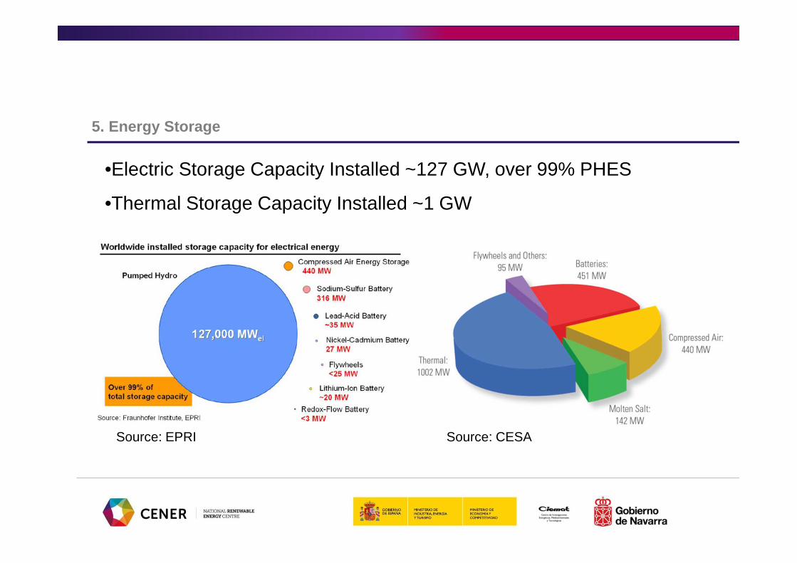
•Electric Storage Capacity Installed ~127 GW, over 99% PHES
•Thermal Storage Capacity Installed ~1 GW
Source: EPRI Source: CESA

5. Energy Storage
• Due to the high diversity of technologies used for energy storage, their role is poorly described in many pathways to a low-carbon economy

5. Energy Storage

5. Energy Storage
Technologies applications Energy vs Power. Source: CENER

5. Energy Storage
Costs reduction Storage supplies or consumes energy whennecessary increasing the efficiency of the gridoperation and reducing the need for newinfrastructures (Managing Transmission & Distributiongrids, supporting Smart Grids,…)
Higher RES share
Storage capabilities make the grid more robust andensure the power supply (new energy servicesMarket, Cross-sector applications,…)
Security of supply & Reliability
What energy storage provides?
Storage smooths the RES variability allowing anenergy system more sustainable (Balancing Demand& Supply)

5. Energy Storage
At distribution level RES integration provokes some concerns mainly related to:• Security of electricity supply (SoES) & System stability
• Voltage control
• Load management & congestion mitigation
Energy Storage can solve these problems providing many ancillary services such as:
• Capacity firming
• Voltage control
• Reactive power compensation
• Power quality

•Main challenges are:
•Maturity of technologies
•Costs (CAPEX & OPEX)
•Regulatory & Market Framework
•Some progress are being done in the last years
•EASE launch (September 2011)
•EERA Storage
•Joint EASE/EERA Recommendations for a European Roadmap Development 2030 (April 2013)
5. Energy Storage

Summary actual state-of-the art repartition
5. Energy Storage

•Main technologies:•Hydrogen
•Batteries
•Supercapacitors
•CAES
•Flywheels
•PHES
•Thermal energy storage
5. Energy Storage

Hydrogen• As electricity H2 is an energy vector and both are complementary
Hydrogen Electricity• Energy is stored as a chemical and fuel• Generally RES are stored as H2 by means of water electrolysis to produce
the gas• Technology chain:
• Applications:• Energy arbitrage, grid services and even seasonal storage• Electrolysers can provide many types of ancillary services• Transport, chemicals
Generation Electrolysis
Transport & Storage
Conversion UseR E S
5. Energy Storage

Hydrogen• Gaps:
• Investment costs (EUR/kW) too high• Efficient large scale components availability• High pressure compression of hydrogen from atmospheric pressure electrolysers is
expensive • Lack of up-scaling experience, e.g. system optimisation packaging and large-scale dynamic
response ability • Efficiency of electrolysis at high cell current density too low • Efficiency of chemical processes to form other synthetic fuels from hydrogen too low • Hydrogen storage materials still in R&D status
• R&D Needs:• Materials (components, electrochemistry, etc.), catalysts, chemical process• Large scale tests• Demo Projects
5. Energy Storage

Batteries• Electricity is stored as chemical energy in electrochemical devices• Different types depending on the chemicals or redox pairs.
• Lead Acid (Pb) • Sodium Sulfur (NaS) • Nickel-based (Ni) • Lithium (Li) • Metal/Air (Zn, Mg, etc.)
• Characteristics:• Rapid response, flexibility and adequate load following• High efficiency charge/discharge cycles, mature technologies• Some of them are toxic and/or pollutants, low energy density/kg and m3
• High costs and limited lifetimes.
5. Energy Storage

Flow Batteries• Electricity is stored as chemical energy in liquid electrolytes pumped from tanks to the
electrochemical stacks• Several types: Vanadium (VRB) , ZnBr
• Characteristics:• Charge: 2 ways• Flexibility and high efficiency• Independent Power (stack cells) and Energy (electrolyte tanks) capacities• Low energy density and technologies under development• High costs
5. Energy Storage
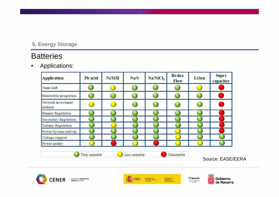
Batteries• Applications:
Source: EASE/EERA
5. Energy Storage
Batteries• Gaps:
• costs • energy density and charging capabilities • power performance • lifetime - degradation during shelf storage as well as during use • Specific functionalities for grid balancing, such as supporting primary and
secondary reserve power, contributing to reserve capacity building and ancillary services to support transmission.
• Electric vehicles
• R&D Needs:• Materials (components, electrochemistry, etc.), catalysts, chemical process• System designs, power electronics for integration with RES & grid• Degradation mechanisms• Modelling
5. Energy Storage

Supercapacitors• An electrochemical capacitor is a device which accumulates electrical energy
in an electric double layer (EDL) which is formed between an electron conducting surface and an electrolyte.
• Characteristics:• Fast charge and high number of cycles• They can operate at very low temperature (<25ºC)• They can absorb a limited amount of electric charge• High efficiency
• Applications• High power applications• Transmission line stability• Spinning reserve • Area and frequency control
5. Energy Storage

Supercapacitors• Gaps:
• High capital costs• Low energy density• Limited use at 10 MW
• R&D Needs: • Electrolytes with higher voltages (>2.7 V)• Proof of concept of asymmetric Li Ion Capacitor (LIC) systems• proof of concept of ceramic EC with dielectric or insulator with very high
permittivity • Basic and applied research on aqueous hybrid systems for very low cost and low
environmental impact using activated carbons • New materials
5. Energy Storage

Compressed Air Energy Storage (CAES) • Off-peak electricity is used to compress air into an underground storage reservoir. The
compressed air is heated by natural gas (diabatic) in combustors or heat from compression (adiabatic) and run through high-pressure and low pressure expanders to produce electricity.
• Characteristics:• Large range of energy stored and long time of storage• Limited natural reservoirs preferred• Low efficiency (diabatic)• Short times to start up and shut down, • high design flexibility and applications, low costs.
• Applications:• Balancing generation and demand, • Provision of secondary and tertiary balancing power, • Black start capability
5. Energy Storage

Compressed Air Energy Storage (CAES) • Gaps:
• Too high investment costs • Nowadays, low round trip efficiency• Use of natural gas for preheating of the compressed air. Not CO2 neutral • Technology Development for Efficient Air Turbines/Expanders• Turbo machinery design for these plants is not “off the shelf” components.
Optimised expanders are not available• Complete System Analysis and Integration with Grid Operation • Cost of Constructing Air Reservoirs & Underground Storage Resources
• R&D Needs:• Adiabatic CAES & components development• New CAES concepts (Low temperature adiabatic systems, Isobaric CAES,
Isothermal CAES, …)• long term impact to the environment assessments
5. Energy Storage

Flywheels• Flywheels store energy mechanically in the form of kinetic energy.• Characteristics:
• Long lifetime (20 years), thousand cycles• Rapid response, high efficiency• Safe devices• High CAPEX, low OPEX
• Applications• High power pulses in milliseconds (particles accelerators)• Nowadays, small flywheels for UPS and transport sector• Renewable energy generation, to ensure the grid stability, frequency regulation and
voltage support. • Military and space control dispositive, industrial applications
5. Energy Storage

Flywheels• Gaps:
• higher energy density flywheels at a lower cost• Electrical machines improvements (related to the speed)• Bearings (conventional, magnetic, superconducting levitation, etc.)• Power electronics suitability (for STATCOM uses)• Digital control and communications• Security case or frame
• R&D Needs: • Better materials for fiber flywheels • High performance Electrical machines at lower cost• Better bearings response and more efficient actuators• Demonstration plants
5. Energy Storage

Pumped Hydro• Energy is stored as potential energy throughout two large water reservoirs
located at different elevations, and once it is released it becomes kinetic energy
• Applications:• peak-load energy supply and grid balancing• primary and secondary regulation and black start
• Characteristics:• Large range of energy and power stored.• High efficiency, connection/disconnection flexibility, rapid start up and shut down and kWh low cost.• High capital costs and long time to install• Large surfaces flooded, high environmental impact, dependent of natural resources
5. Energy Storage
Pumped Hydro• Gaps:
• More flexibility for new applications (frequency regulation)• Pump turbines performance improvements (variable speed)• New PHES concepts (avoiding geographical concerns)• Suitable and available equipment for very high head and low head sites.
• R&D Needs:• Develop new turbines (upgrading existing PHES and new services)• Sea water PHES and new concepts as Energy Island • Minimisation of environmental impacts • smaller demonstration projects for new PHES concept • Development of standardised mini/micro cost-competitive PHES and hybrid PHES-
wind/photovoltaic applications for centralised and decentralised solutions
5. Energy Storage

Thermal storage• Energy is stored as heat in solids and fluids even at low temperature• Mechanisms:
• Sensible heat (temperature)• Latent heat (phase change)• Thermochemical Heat Storage
• Especially adequate to solar thermal plants• Heating and cooling of buildings
Absorber tube
Reflector
5. Energy Storage
Thermal storage• Gaps:
• Too high investment costs• Low energy density and Low heat conductivity of thermal storage systems• Reliability of thermal energy storage systems • Too large loss of heat over time• Insufficient knowledge about system integration and Demand Side Management (DMS)
in combination with Electric Storage Heaters. • Insufficient knowledge about environmental impacts
• R&D Needs:• New materials development and integration of phase change materials in building
element materials • Research of large scale solar heating systems • Identify advanced heat transfer mechanisms for charging and discharging • Optimisation of hydraulics in advanced water stores
SgID9mKt
5. Energy Storage

Objective:
Theoretical and experimental studies in the experimental plant for hydrogen production and storage installed in Parque de Sotavento (Galicia)
Customer: Gas Natural Duration: 30 months
Study of the hydrogen production and storage plant in Parque Eólico Experimental de Sotavento
Relevant projects
Conceptual engineering of a zinc-bromine flow battery of 1 kW power
Objective:
Conceptual design of a 1kW ZnBr battery prototype and economical analysis
Customer: Sun to Market Solutions (S2M) Duration: 6 months

stoRE- Facilitating energy storage to allow high penetration of intermittent renewable energy
Objective :
Analysis of storage needs in Europe mid-term and study of regulatory and market framework as in Europe as national level to propose recommendations and improvements
Financed by: Intelligent Energy Europe Duration: 36 months
Relevant projects
Characterization and testing of redox batteries ZnBr for Smart-Grids (Prower Flow)
Objective:
Testing, characterizations and validation of a ZnBr flow battery according the procedures in a real microgrid
Customer: Jofemar Duration: 18 months

Objetive:
LIFE+ ZAESS project aims to demonstrate an energy storage technology based on Zn-air batteries for increasing the share of intermittent renewable energies in the European energy mix and reducing CO2 emissions thereby
Partners: Técnicas Reunidas (LIFE13 ENV/ES/001159) Duration: 40 meses
Life-ZAESS-Demonstration of a low cost and environmentally friendly Zinc Air Energy Storage System for renewable energy integration
STORY-added value of STORage in distribution sYstems
Objetive:
to show the added value of using storage in the low and medium voltage grid. 8 demonstrations are set up to feed knowledge into the further analysis on large scale impact assessment and on market models, policy & regulation.
Partners: 18 from 7 countries H2020-LCE-2014-8 Duration: 5 years
Relevant projects

6. Regulatory and Market Framework

6. Regulatory and Market Framework
Electricity Market
•Royal Decree 2019/1997 regulates the market of power generation
•RD 1435/2002 regulates the energy purchase and access to the Distribution Network
•RD 134&1221/2010 modify the RD 2019/1997 and define the procedure for restrictions of guaranty of supply
•RD-Law 14/2010 “actions to correct the tariff deficit of the electricity sector”

Renewables General
•Law 54/1997 of electric sector:
•defined the electricity sector operation (liberalization)
•added the goal of RES contribution of 12% to the total energy consumption in 2010.
•RES Promotion Plan December 1999
•RES Plan 2005-2010 [PER]:
•Additional goals: +5.83% biofuels and +29.4% of RES contribution to electricity
•Directive 2009/28/CE: binding goals 20-20-20 + 10% in transport
6. Regulatory and Market Framework

Renewables
•RD 661/2007 regulates the power generation in Special Regime (RES and cogeneration <50 MW)
•Classification of Special Regime Power Generators
•Feed-in tariffs depending on the technology
•RD 1699/2011 “Grid connection of low power facilities (self-consumption)”
•RD-Law 1/2012 “Moratorium for RES incentives”
•RD-Law 2/2013 “Actions in the energy and financial sectors”
6. Regulatory and Market Framework
6. Regulatory and Market Framework
Renewables
•RD-law 9/2013, 12 July, “Emergency Actions for ensuringfinancial stability of electricity sector”
•Law 24/2013, 26 December, “Electricity Sector”
•RD 413/2014, 6 June, regulates the power generation from renewable energies, cogeneration and waste
•RD 900/2015, 9 October, “self-consumption plants”

OMIE
Market Management:
auctions & operation
REE
Technical Management:
ancillary services,
restrictions & deviations
CNMC
Subsidies & Complements
Utilities
Interlocution
•Participants
6. Regulatory and Market Framework

OMIE
Offers Day & Intraday Markets
REE
Deviations
CNMC
Subsidies & Complements
Utilities
Financial balances &
Incomes from OMIE and
REE
•Roles
6. Regulatory and Market Framework

•Smart Grids & Storage
•Communications from the Commission
• Smart Grids: from innovation to deployment (COM(2011) 202 final)
• Progress towards Completing the Internal Energy Market (COM (2014) 634).
• Delivering a New Deal for Energy Consumers, (COM(2015) 339 final)
• Best practices on Renewable Energy Self-consumption
• Others in progress…
6. Regulatory & Market Framework

7. Conclusions

7. Conclusions
• Successful integration of high shares of renewables in Spain
• Regulatory and Market Framework is key for the development of the renewable energy sector
• Control and supervision of RES generation needed to maximize RES integration maintaining security of supply. Technical concerns solved by the TSO throughout CECRE
• Evolution of the centralised & conventional power generation based energy model towards a decentralised & RES based model.
• New grid challenges to be addressed due to RES integration at distribution level
• Smart Grids and Energy Storage as key solutions• They provide new energy services and support new market schemes