Rendering(Complex(Scenes(with( Memory7CoherentRay(Tracing(
17
Rendering Complex Scenes with MemoryCoherent Ray Tracing Ma: Pharr, Craig Kolb, Reid Gershbein, Pat Hanrahan Ma: Patchin
Transcript of Rendering(Complex(Scenes(with( Memory7CoherentRay(Tracing(

Rendering Complex Scenes with Memory-‐Coherent Ray Tracing
Ma: Pharr, Craig Kolb, Reid Gershbein, Pat Hanrahan
Ma: Patchin

The Goal
• Rendering Systems are challenged by three types of complexity: – Geometric – Surface – IlluminaEon
• Handling all three at one had not been previously possible.
The Goal
• Generally speaking, some sacrifices were made with respect to these complexiEes in order to achieve reasonable run Emes
• Sought to recEfy this by improving the coherence of the scene.

Overview
• Developed algorithms based two main ideas: – Caching –cached a subset of large geometric objects and textures in memory for fast access.
– Reordering-‐ In order to ensure coherent access, scene data and ray intersecEon calculaEons were reordered and placed into memory.
• These algorithms made it possible to efficiently compute incredibly complex images

Overview
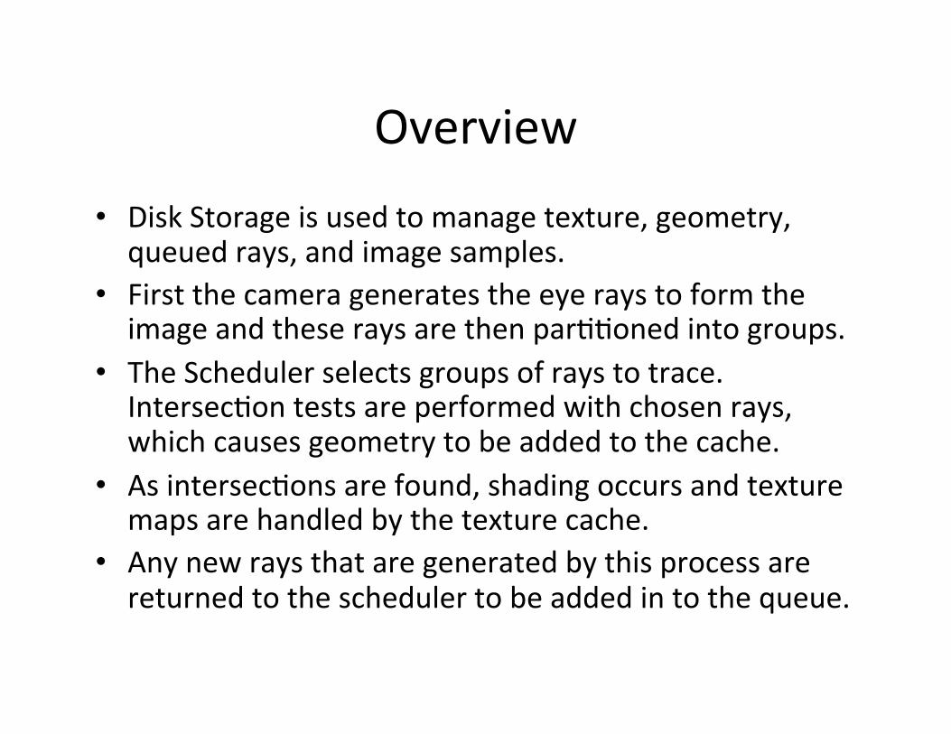
Overview • Disk Storage is used to manage texture, geometry, queued rays, and image samples.
• First the camera generates the eye rays to form the image and these rays are then parEEoned into groups.
• The Scheduler selects groups of rays to trace. IntersecEon tests are performed with chosen rays, which causes geometry to be added to the cache.
• As intersecEons are found, shading occurs and texture maps are handled by the texture cache.
• Any new rays that are generated by this process are returned to the scheduler to be added in to the queue.

Caching Scene Data
• Cache texture and geometric informaEon to manage scene complexity.
• Limited amount is stored in memory and lazy loading limits what is added to the cache.
• Both caches use a least recently used replacement policy.

Caching Scene Data
• Geometric Sources – Only use triangles. – Advantages • Ray intersecEon can be opEmized. • Memory management for geometry cache is easier. • Other parts of the renderer can be opEmized when only one type of primiEve is supported.
– Disadvantage • Some primiEves, such as spheres, require more space to store aUer tessellaEon.

Caching Scene Data
• Geometry Cache ProperEes – Organized around voxel grids called Geometry grids. – All geometry in a voxel occupies a conEguous block of memory independent of geometry in other voxels. ParEcularly, triangles that span mulEple voxels are stored independently in each of them.
– Reasoning for this was that the spaEal locality in the 3D space of the scene is Eed to the spaEal locality in memory. This way coherent access in 3D space generates coherent access in memory.

Caching Scene Data
• Geometry Cache ProperEes – Memory management in the geometry cache is more complicated than in the texture cache.
– Fixed this by introducing their own allocaEon rouEnes.
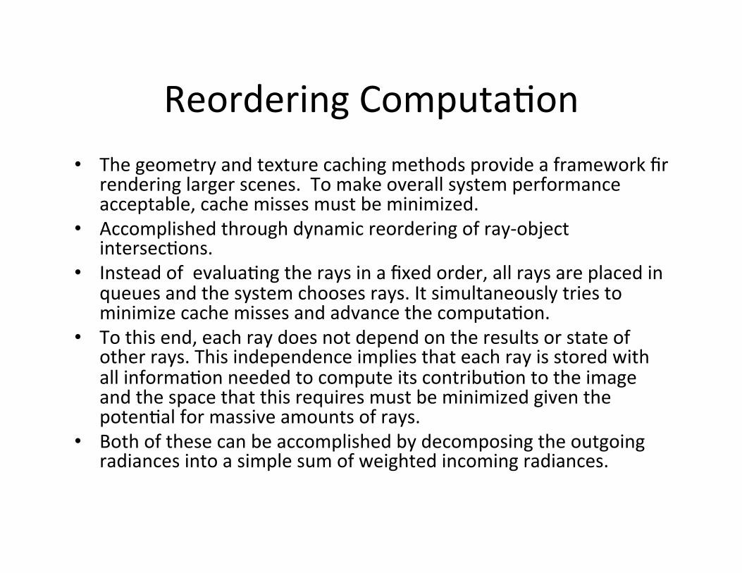
Reordering ComputaEon • The geometry and texture caching methods provide a framework fir
rendering larger scenes. To make overall system performance acceptable, cache misses must be minimized.
• Accomplished through dynamic reordering of ray-‐object intersecEons.
• Instead of evaluaEng the rays in a fixed order, all rays are placed in queues and the system chooses rays. It simultaneously tries to minimize cache misses and advance the computaEon.
• To this end, each ray does not depend on the results or state of other rays. This independence implies that each ray is stored with all informaEon needed to compute its contribuEon to the image and the space that this requires must be minimized given the potenEal for massive amounts of rays.
• Both of these can be accomplished by decomposing the outgoing radiances into a simple sum of weighted incoming radiances.

Reordering ComputaEon
• ComputaEon DecomposiEon
Reordering ComputaEon
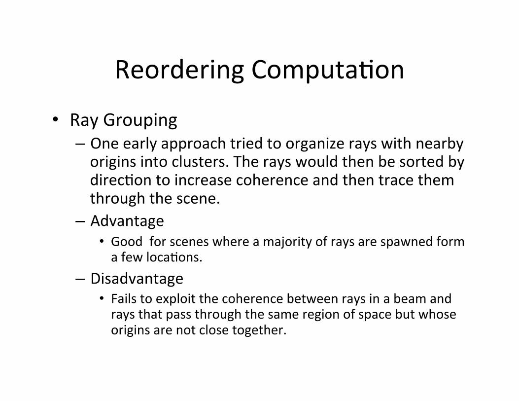
• Ray Grouping – One early approach tried to organize rays with nearby origins into clusters. The rays would then be sorted by direcEon to increase coherence and then trace them through the scene.
– Advantage • Good for scenes where a majority of rays are spawned form a few locaEons.
– Disadvantage • Fails to exploit the coherence between rays in a beam and rays that pass through the same region of space but whose origins are not close together.

Reordering ComputaEon
• Ray Grouping – The approach they decide on was designed to account fir spaEal coherence between all rays.
– Scene was divided into another set of voxels called the scheduling grid. Associated with each voxel is a queue of the rays currently inside it and informaEon regarding its geometry.
– If an intersecEon is found, shade and calculate spawned rays. Otherwise the ray is advanced to the next non-‐empty voxel and placed on the voxels ray queue.

Results They tested their algorithms with three complex scenes

Results
• Caching – Rendered the Cathedral Scene twice and Office Scene once.
– Texture cache also performed extremely well.

Results
• Reordering – Lake scene was used to test performance of reordering.


![Ray Tracing Dynamic Scenes using Selective Restructuringgamma.cs.unc.edu/SR/Selective.pdf · Ray Tracing Dynamic Scenes using Selective Restructuring ... [LM03, TKH 05]. A BVH is](https://static.fdocuments.us/doc/165x107/5c8d871f09d3f219388cac81/ray-tracing-dynamic-scenes-using-selective-ray-tracing-dynamic-scenes-using.jpg)