A Graphics Pipeline for Directly Rendering 3D Scenes on Web Browsers
A Graphics Pipeline for DirectlyRendering 3D Scenes on Web Browsers
Master’s Thesis
!
Edgar Marchiel Pinto

A Graphics Pipeline for DirectlyRendering 3D Scenes on Web Browsers
DISSERTATION
concerning to the investigation work done to obtain the degree of
MASTER OF SCIENCE
in
COMPUTER SCIENCE AND ENGINEERING
by
Edgar Marchiel Pintonatural of Covilha, Portugal
!
Computer Graphics and Multimedia GroupDepartment of Computer Science
University of Beira InteriorCovilha, Portugalwww.di.ubi.pt

Copyright c© 2009 by Edgar Marchiel Pinto. All right reserved. No part of this publica-tion can be reproduced, stored in a retrieval system, or transmitted, in any form or by anymeans, electronic, mechanical, photocopying, recording, or otherwise, without the previouswritten permission of the author.
A Graphics Pipeline for DirectlyRendering 3D Scenes on Web Browsers
Author: Edgar Marchiel PintoStudent Id: M1489
Resumo
Nesta dissertacao propomos um pipeline grafico, na forma de uma biblioteca Web-3D, para a renderizacao de cenas 3D directamente no browser. Esta biblioteca decodigo livre chama-se Glyper3D. Foi desenvolvida usando a linguagem de programacaoJavaScript, em conjunto com o elemento canvas do HTML5, permitindo a criacao, ma-nipulacao e renderizacao de conteudos 3D no browser, sem ser necessaria a instalacaode qualquer tipo de plug-in ou add-on para o browser, ou seja, nao tira partido deaceleracao grafica. Esta e a principal diferenca em relacao a outras tecnologias Web3D.Como e uma biblioteca direccionada para um ambiente web, foi desenvolvida para pro-porcionar maior usabilidade, proporcionando assim uma forma mais simples e intuitivapara desenvolver conteudos 3D directamente no browser. Glypher3D pode ser usadapara melhorar uma pagina web em varios aspectos, pois permite a criacao de logoti-pos em 3D, modelos geometricos, entre outros propositos. E uma biblioteca multi-plataforma e funciona em todos os browsers compatıveis com o elemento canvas doHTML5, como o Firefox, Safari, Opera e Chrome.
Supervisor: Prof. Dr. Abel Gomes, DI, University of Beira Interior

A Graphics Pipeline for DirectlyRendering 3D Scenes on Web Browsers
Author: Edgar Marchiel PintoStudent Id: M1489
Abstract
In this dissertation we propose a graphics pipeline, in the form of a Web3D graph-ics library, for directly rendering 3D scenes on web browsers. This open source Web3Dgraphics library is called Glypher3D. It is entirely written in JavaScript (together withthe HTML5 canvas element) and aims at enabling the creation, manipulation and ren-dering of 3D contents within a browser, without the need of installing any type ofweb browser plug-ins or add-ons (i.e. it does not take advantage of hardware acceler-ation), which is the main difference when compared to other Web3D technologies. Asa library intended for the web environment, it was developed having in mind usabil-ity, therefore it is a simple and more intuitive way to deploy 3D contents on browser.Glypher3D can be used to enhance an web page, by allowing the creation of 3D logos,models, advertisements, among other purposes. Its a multi-platform library and worksin the HTML5 canvas-compatible browsers like Firefox, Safari, Opera and Chrome.
Supervisor: Prof. Dr. Abel Gomes, DI, University of Beira Interior

Preface
First, I would like to thank to my supervisor Prof. Dr. Abel Gomes for all the patience,dedication and transmitted knowledge during the realization of this dissertation.
I am also thankful to all my family and friends for all the support provided during myacademic and personal life.
Edgar Marchiel Pinto
vii

Contents
Preface vii
Contents ix
List of Figures xiii
1 Introduction 11.1 Motivation . . . . . . . . . . . . . . . . . . . . . . . . . . . . . . . . . . . 11.2 Research Issues and Contributions . . . . . . . . . . . . . . . . . . . . . . 21.3 Organization of the Thesis . . . . . . . . . . . . . . . . . . . . . . . . . . 3
2 3D Web Graphics: The State-of-the-Art 52.1 VRML . . . . . . . . . . . . . . . . . . . . . . . . . . . . . . . . . . . . . 52.2 X3D . . . . . . . . . . . . . . . . . . . . . . . . . . . . . . . . . . . . . . 82.3 Java3D . . . . . . . . . . . . . . . . . . . . . . . . . . . . . . . . . . . . 122.4 Flash 3D . . . . . . . . . . . . . . . . . . . . . . . . . . . . . . . . . . . . 152.5 C3DL . . . . . . . . . . . . . . . . . . . . . . . . . . . . . . . . . . . . . 182.6 Other Web3D Technologies . . . . . . . . . . . . . . . . . . . . . . . . . . 20
2.6.1 Ajax3D . . . . . . . . . . . . . . . . . . . . . . . . . . . . . . . . 212.6.2 3DMLW . . . . . . . . . . . . . . . . . . . . . . . . . . . . . . . 212.6.3 O3D . . . . . . . . . . . . . . . . . . . . . . . . . . . . . . . . . . 22
2.7 Summary . . . . . . . . . . . . . . . . . . . . . . . . . . . . . . . . . . . 23
3 Glypher3D 253.1 The Canvas Element . . . . . . . . . . . . . . . . . . . . . . . . . . . . . 253.2 Client-Side Architecture . . . . . . . . . . . . . . . . . . . . . . . . . . . 263.3 Rendering Pipeline . . . . . . . . . . . . . . . . . . . . . . . . . . . . . . 283.4 Creation of the Canvas 2D Rendering Context . . . . . . . . . . . . . . . . 303.5 Creation of the 3D Scene . . . . . . . . . . . . . . . . . . . . . . . . . . . 32
3.5.1 Glypher3D 3D Coordinate System . . . . . . . . . . . . . . . . . . 323.5.2 Points . . . . . . . . . . . . . . . . . . . . . . . . . . . . . . . . . 32
ix
CONTENTS
3.5.3 Shape . . . . . . . . . . . . . . . . . . . . . . . . . . . . . . . . . 333.5.4 Lines . . . . . . . . . . . . . . . . . . . . . . . . . . . . . . . . . 343.5.5 Triangles . . . . . . . . . . . . . . . . . . . . . . . . . . . . . . . 353.5.6 Quads . . . . . . . . . . . . . . . . . . . . . . . . . . . . . . . . . 363.5.7 Scene . . . . . . . . . . . . . . . . . . . . . . . . . . . . . . . . . 36
3.6 Geometric Transformations . . . . . . . . . . . . . . . . . . . . . . . . . . 363.6.1 Rotation . . . . . . . . . . . . . . . . . . . . . . . . . . . . . . . . 373.6.2 Translation . . . . . . . . . . . . . . . . . . . . . . . . . . . . . . 393.6.3 Scaling . . . . . . . . . . . . . . . . . . . . . . . . . . . . . . . . 393.6.4 Shearing . . . . . . . . . . . . . . . . . . . . . . . . . . . . . . . 40
3.7 Light and Viewer Positions . . . . . . . . . . . . . . . . . . . . . . . . . . 413.8 Hidden Surface Removal Algorithms . . . . . . . . . . . . . . . . . . . . . 41
3.8.1 Painter’s Algorithm . . . . . . . . . . . . . . . . . . . . . . . . . . 423.8.2 Back-Face Culling Algorithm . . . . . . . . . . . . . . . . . . . . 43
3.9 Coloring and Shading . . . . . . . . . . . . . . . . . . . . . . . . . . . . . 453.9.1 Background Color . . . . . . . . . . . . . . . . . . . . . . . . . . 453.9.2 Wireframe Color . . . . . . . . . . . . . . . . . . . . . . . . . . . 463.9.3 Fill Color . . . . . . . . . . . . . . . . . . . . . . . . . . . . . . . 473.9.4 Flat Shading . . . . . . . . . . . . . . . . . . . . . . . . . . . . . 483.9.5 Gouraud Shading . . . . . . . . . . . . . . . . . . . . . . . . . . . 49
3.9.5.1 Vertex Normals . . . . . . . . . . . . . . . . . . . . . . 493.9.5.2 Color Intensity of Vertices . . . . . . . . . . . . . . . . . 493.9.5.3 Color Intensity of Pixels . . . . . . . . . . . . . . . . . . 51
3.10 Projection Transformations . . . . . . . . . . . . . . . . . . . . . . . . . . 533.10.1 Parallel Projection . . . . . . . . . . . . . . . . . . . . . . . . . . 533.10.2 Perspective Projection . . . . . . . . . . . . . . . . . . . . . . . . 54
3.11 Display . . . . . . . . . . . . . . . . . . . . . . . . . . . . . . . . . . . . 553.12 Summary . . . . . . . . . . . . . . . . . . . . . . . . . . . . . . . . . . . 58
4 Results 594.1 Glypher3D Scenes . . . . . . . . . . . . . . . . . . . . . . . . . . . . . . 594.2 Rendering Performance . . . . . . . . . . . . . . . . . . . . . . . . . . . . 62
4.2.1 Mac Platform . . . . . . . . . . . . . . . . . . . . . . . . . . . . . 634.2.2 Windows Platform . . . . . . . . . . . . . . . . . . . . . . . . . . 644.2.3 HTML5 and SVG . . . . . . . . . . . . . . . . . . . . . . . . . . 66
4.3 Summary . . . . . . . . . . . . . . . . . . . . . . . . . . . . . . . . . . . 67
5 Conclusions and Future Work 695.1 Conclusions . . . . . . . . . . . . . . . . . . . . . . . . . . . . . . . . . . 695.2 Future Work . . . . . . . . . . . . . . . . . . . . . . . . . . . . . . . . . . 70
Bibliography 73
A Glossary 77
x
CONTENTS
B Web3D Technologies Resources 79B.1 VRML and X3D . . . . . . . . . . . . . . . . . . . . . . . . . . . . . . . 79
B.1.1 Players . . . . . . . . . . . . . . . . . . . . . . . . . . . . . . . . 79B.1.2 Authoring Tools . . . . . . . . . . . . . . . . . . . . . . . . . . . 80B.1.3 Online Resources . . . . . . . . . . . . . . . . . . . . . . . . . . . 80
B.2 Java3D . . . . . . . . . . . . . . . . . . . . . . . . . . . . . . . . . . . . 81B.2.1 Online Resources . . . . . . . . . . . . . . . . . . . . . . . . . . . 81
B.3 Flash 3D . . . . . . . . . . . . . . . . . . . . . . . . . . . . . . . . . . . . 81B.3.1 Flash engines . . . . . . . . . . . . . . . . . . . . . . . . . . . . . 81B.3.2 Online Resources . . . . . . . . . . . . . . . . . . . . . . . . . . . 82
B.4 C3DL . . . . . . . . . . . . . . . . . . . . . . . . . . . . . . . . . . . . . 83B.4.1 Online Resources . . . . . . . . . . . . . . . . . . . . . . . . . . . 83
B.5 Ajax3D . . . . . . . . . . . . . . . . . . . . . . . . . . . . . . . . . . . . 84B.5.1 Online Resources . . . . . . . . . . . . . . . . . . . . . . . . . . . 84
B.6 3DMLW . . . . . . . . . . . . . . . . . . . . . . . . . . . . . . . . . . . . 84B.6.1 Online Resources . . . . . . . . . . . . . . . . . . . . . . . . . . . 84
B.7 O3D . . . . . . . . . . . . . . . . . . . . . . . . . . . . . . . . . . . . . . 84B.7.1 Online Resources . . . . . . . . . . . . . . . . . . . . . . . . . . . 84
xi

List of Figures
2.1 Box rendered through the VRML browser plug-in Cortona3D Viewer 6, withFirefox 3.0 on Windows XP SP3. . . . . . . . . . . . . . . . . . . . . . . . . . 7
2.2 Virtual chamber rendered through the VRML browser plug-in Cortona3D Viewer6, with Firefox 3.0 on Windows XP SP3. Retrieved from [32]. . . . . . . . . . 8
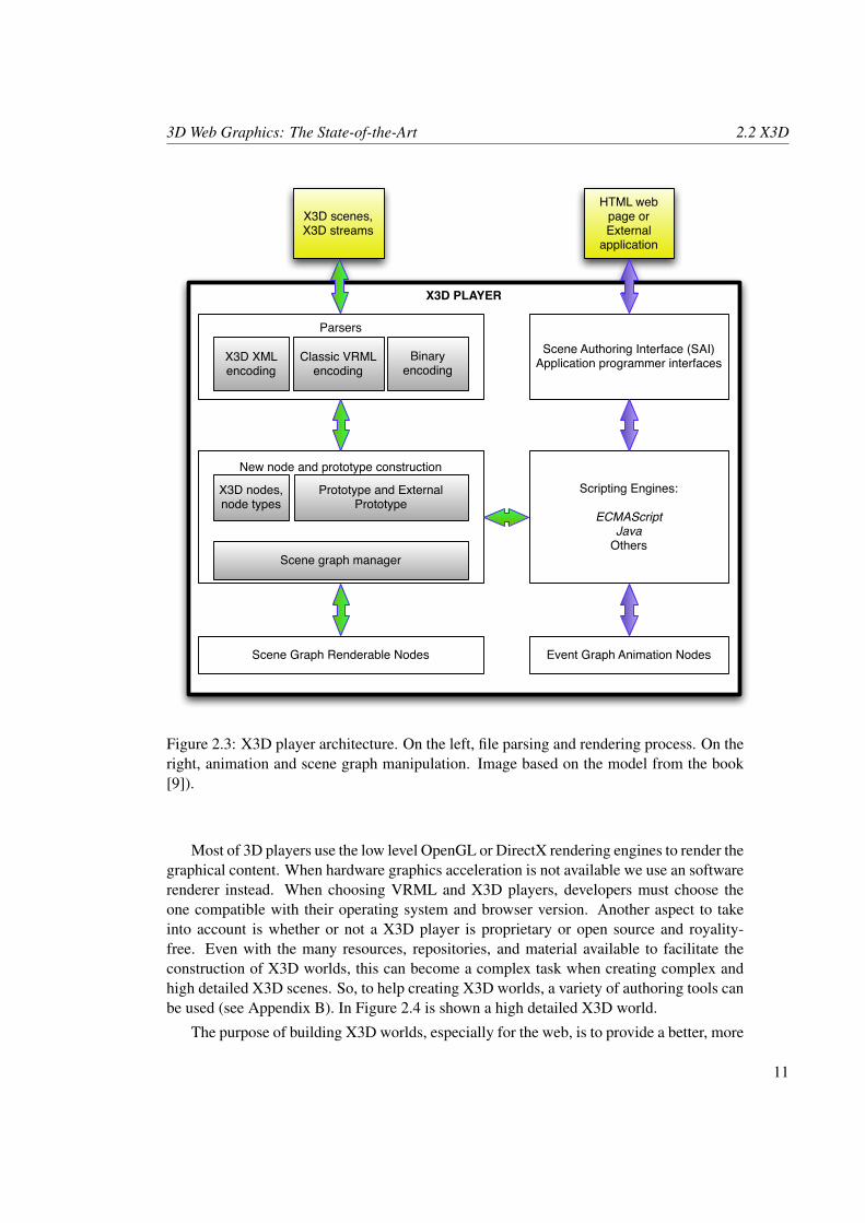
2.3 X3D player architecture. On the left, file parsing and rendering process. Onthe right, animation and scene graph manipulation. Image based on the modelfrom the book [9]). . . . . . . . . . . . . . . . . . . . . . . . . . . . . . . . . 11
2.4 Shark rendered through the X3D browser plug-in Octaga Player 2.30.05, withFirefox 3.0 on Windows XP SP3. Retrieved from [32]. . . . . . . . . . . . . . 12
2.5 HelloJava3Dd.class applet running in Firefox 3.0 on Windows XP SP3.The client machine as installed the Java 2 Runtime Environment SE v1.6.0, Java3D 1.5.1 and Java plug-in 1.6.0. . . . . . . . . . . . . . . . . . . . . . . . . . 14
2.6 Enigma Cipher Machine applet running in Firefox 3.0 on Windows XP SP3.Retrieved from [24]. . . . . . . . . . . . . . . . . . . . . . . . . . . . . . . . 14
2.7 Flash CS4 Simple 3D Cube running in Windows XP SP3 with Firefox 3.0 andAdobe Flash Player 10. Flash file downloaded from [15]. . . . . . . . . . . . . 17
2.8 Rich and interactive web 3D scene achieved through the Sophie3D flash engine.Retrieved from [13]. . . . . . . . . . . . . . . . . . . . . . . . . . . . . . . . 17
2.9 This scene shows a duck model loaded from a COLLADA file with textureapplied. C3DL scene rendered using the Canvas 3D add-on 0.4.3 with Firefox3.5 on Mac OS X v.10. Source code and model downloaded from [8]. . . . . . 19
2.10 This scene shows a motion capture demo with spheres. C3DL scene renderedusing the Canvas 3D add-on v.0.4.3 with Firefox 3.5 on Mac OS X v.10. Re-trieved from [8]. . . . . . . . . . . . . . . . . . . . . . . . . . . . . . . . . . . 20
2.11 Ajax3D logotype rendered using the Vivaty plug-in v.0.9 with Internet Explorer7 on Windows XP SP3. Retrieved from [6]. . . . . . . . . . . . . . . . . . . . 21
2.12 3DMLW band room scene rendered using the 3DMLW plug-in v.1.0.5 withFirefox 3.0 on Windows XP SP3. Retrieved from [35]. . . . . . . . . . . . . . 22
2.13 Earth surface with complex textures. O3D scene rendered using the O3D plug-in v.0.1 with Firefox 3.5 on Mac OS X v.10. Retrieved from [18]. . . . . . . . . 23
xiii
List of Figures List of Figures
3.1 Glypher3D Client-Side Architecture. . . . . . . . . . . . . . . . . . . . . . . . 273.2 Glypher3D Rendering Pipeline. . . . . . . . . . . . . . . . . . . . . . . . . . . 293.3 Glypher3D 2D coordinate system. . . . . . . . . . . . . . . . . . . . . . . . . 323.4 Glypher3D right-handed 3D coordinate system. . . . . . . . . . . . . . . . . . 333.5 Glypher3D graphics primitives. . . . . . . . . . . . . . . . . . . . . . . . . . . 353.6 Glypher3D scene composition. . . . . . . . . . . . . . . . . . . . . . . . . . . 373.7 Glypher3D light position. . . . . . . . . . . . . . . . . . . . . . . . . . . . . . 423.8 Glypher3D painter’s algorithm. On the left, a cube without the algorithm, on
the right, a cube with the algorithm. . . . . . . . . . . . . . . . . . . . . . . . 433.9 Surface normal vector on a quad shape, as well as the vectors created with three
of the four vertices. . . . . . . . . . . . . . . . . . . . . . . . . . . . . . . . . 443.10 Glypher3D back-face culling algorithm. On the left, a cube without the algo-
rithm, on the right, a cube with the algorithm. . . . . . . . . . . . . . . . . . . 453.11 Illustration of applying the background, wireframe, and fill coloring methods.
On the left, a red wireframe cube, on the right, a red filled cube. . . . . . . . . 473.12 Glypher3D flat shading and Gouraud shading algorithms. On the left, a flat
shaded pyramid, on the right, a Gouraud shaded pyramid. . . . . . . . . . . . . 493.13 Intensities for each pixel of the triangle along scan lines using linear interpolation. 513.14 Glypher3D parallel and perspective projections applied to a pyramid. . . . . . . 553.15 Glypher3D drawing methods. On the left, a wireframe tetrahedron, on the right,
a shaded cube. For both, all visible vertices are drawn. . . . . . . . . . . . . . 57
4.1 Glypher3D triangle fan shape with rotation, painter’s algorithm, Gouraud shad-ing, and perspective projection facilities. Scene rendered with Safari 4 on MacOS X v.10.5.7. . . . . . . . . . . . . . . . . . . . . . . . . . . . . . . . . . . . 61
4.2 Glypher3D scene with multiple shapes, i.e, compounded of lines, triangles andquad primitives. Scene rendered with Safari 4 on Mac OS X v.10.5.7. . . . . . 61
4.3 Fully functional Glypher3D web application running with Firefox 3.5 on MacOS X v.10.5.7. . . . . . . . . . . . . . . . . . . . . . . . . . . . . . . . . . . . 62
4.4 Glypher3D rendering performance of Gouraud shaded objects with Firefox 3.5,Safari 4 and Opera 10 on Mac OS X v.10.5.7. . . . . . . . . . . . . . . . . . . 63
4.5 Glypher3D rendering performance of flat shaded objects with Firefox 3.5, Sa-fari 4 and Opera 10 on Mac OS X v.10.5.7. . . . . . . . . . . . . . . . . . . . 64
4.6 Glypher3D rendering performance of Gouraud shaded objects with Firefox 3.5,Safari 4, Opera 10 and Chrome 2 on Windows XP SP3 . . . . . . . . . . . . . . 65
4.7 Glypher3D rendering performance of flat shaded objects with Firefox 3.5, Sa-fari 4, Opera 10, Chrome 2 and Internet Explorer 7 on Windows XP SP3. . . . 66
4.8 Rendering performance between the HTML5 canvas element and SVG withFirefox 3.5 on Mac OS X v.10.5.7. . . . . . . . . . . . . . . . . . . . . . . . . 67
4.9 Rendering performance between the HTML5 canvas element and SVG withFirefox 3.5 on Windows XP SP3. . . . . . . . . . . . . . . . . . . . . . . . . . 68
xiv
Chapter 1
Introduction
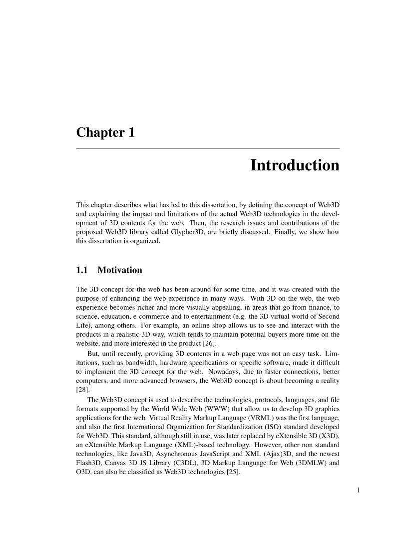
This chapter describes what has led to this dissertation, by defining the concept of Web3Dand explaining the impact and limitations of the actual Web3D technologies in the devel-opment of 3D contents for the web. Then, the research issues and contributions of theproposed Web3D library called Glypher3D, are briefly discussed. Finally, we show howthis dissertation is organized.
1.1 Motivation
The 3D concept for the web has been around for some time, and it was created with thepurpose of enhancing the web experience in many ways. With 3D on the web, the webexperience becomes richer and more visually appealing, in areas that go from finance, toscience, education, e-commerce and to entertainment (e.g. the 3D virtual world of SecondLife), among others. For example, an online shop allows us to see and interact with theproducts in a realistic 3D way, which tends to maintain potential buyers more time on thewebsite, and more interested in the product [26].
But, until recently, providing 3D contents in a web page was not an easy task. Lim-itations, such as bandwidth, hardware specifications or specific software, made it difficultto implement the 3D concept for the web. Nowadays, due to faster connections, bettercomputers, and more advanced browsers, the Web3D concept is about becoming a reality[28].
The Web3D concept is used to describe the technologies, protocols, languages, and fileformats supported by the World Wide Web (WWW) that allow us to develop 3D graphicsapplications for the web. Virtual Reality Markup Language (VRML) was the first language,and also the first International Organization for Standardization (ISO) standard developedfor Web3D. This standard, although still in use, was later replaced by eXtensible 3D (X3D),an eXtensible Markup Language (XML)-based technology. However, other non standardtechnologies, like Java3D, Asynchronous JavaScript and XML (Ajax)3D, and the newestFlash3D, Canvas 3D JS Library (C3DL), 3D Markup Language for Web (3DMLW) andO3D, can also be classified as Web3D technologies [25].
1
1.2 Research Issues and Contributions Introduction
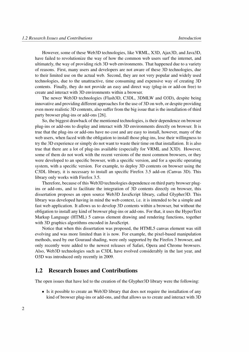
However, some of these Web3D technologies, like VRML, X3D, Ajax3D, and Java3D,have failed to revolutionize the way of how the common web users surf the internet, andultimately, the way of providing rich 3D web environments. That happened due to a varietyof reasons. First, many users and developers are not aware of these 3D technologies, dueto their limited use on the actual web. Second, they are not very popular and widely usedtechnologies, due to the unattractive, time consuming and expensive way of creating 3Dcontents. Finally, they do not provide an easy and direct way (plug-in or add-on free) tocreate and interact with 3D environments within a browser.
The newer Web3D technologies (Flash3D, C3DL, 3DMLW and O3D), despite beinginnovative and providing different approaches for the use of 3D on web, or despite providingeven more realistic 3D contents, also suffer from the big issue that is the installation of thirdparty browser plug-ins or add-ons [26].
So, the biggest drawback of the mentioned technologies, is their dependence on browserplug-ins or add-ons to display and interact with 3D environments directly on browser. It istrue that the plug-ins or add-ons have no cost and are easy to install, however, many of theweb users, when faced with the obligation to install those plug-ins, lose their willingness totry the 3D experience or simply do not want to waste their time on that installation. It is alsotrue that there are a lot of plug-ins available (especially for VRML and X3D). However,some of them do not work with the recent versions of the most common browsers, or theywere developed to an specific browser, with a specific version, and for a specific operatingsystem, with a specific version. For example, to deploy 3D contents on browser using theC3DL library, it is necessary to install an specific Firefox 3.5 add-on (Canvas 3D). Thislibrary only works with Firefox 3.5.
Therefore, because of this Web3D technologies dependence on third party browser plug-ins or add-ons, and to facilitate the integration of 3D contents directly on browser, thisdissertation proposes an open source Web3D JavaScript library, called Glypher3D. Thislibrary was developed having in mind the web context, i.e. it is intended to be a simple andfast web application. It allows us to develop 3D contents within a browser, but without theobligation to install any kind of browser plug-ins or add-ons. For that, it uses the HyperTextMarkup Language (HTML) 5 canvas element drawing and rendering functions, togetherwith 3D graphics algorithms encoded in JavaScript.
Notice that when this dissertation was proposed, the HTML5 canvas element was stillevolving and was more limited than it is now. For example, the pixel-based manipulationmethods, used by our Gouraud shading, were only supported by the Firefox 3 browser, andonly recently were added to the newest releases of Safari, Opera and Chrome browsers.Also, Web3D technologies such as C3DL have evolved considerably in the last year, andO3D was introduced only recently in 2009.
1.2 Research Issues and Contributions
The open issues that have led to the creation of the Glypher3D library were the following:
• Is it possible to create an Web3D library that does not require the installation of anykind of browser plug-ins or add-ons, and that allows us to create and interact with 3D
2
Introduction 1.3 Organization of the Thesis
contents directly on browser?
• By not using any plug-in or add-on, as those used by all the mentioned Web3D tech-nologies to take advantage of software or hardware acceleration (through OpenGL1
or DirectX 2), how would it be the rendering performance of the library?
• Also, by not using any plug-in or add-on, would it be the HTML5 canvas element,together with JavaScript, the best technology to draw 2D graphics for the web?
• By using this technology, would Glypher3D be a cross platform and a browser-independent library?
So, the goal of this dissertation is to answer to those questions, by describing in whataspects Glypher3D differentiates itself from the most used Web3D technologies, as well asby explaining in detail the Glypher3D library architecture, rendering pipeline and all of itsfunctionalities.
The main contribution of this dissertation is then to facilitate the integration of 3D con-tents within a web page, by proposing an open source Web3D graphics library (Glypher3D),that allows us to create, manipulate, and display 3D contents directly on browser, in a moreintuitive and easier way (without browser plug-ins or add-ons) than other Web3D technolo-gies.
1.3 Organization of the Thesis
This dissertation is organized into five chapters, as follows:
• Chapter 1. In this chapter we overview the Web3D concept and Web3D technologies.The research issues that led to the Glypher3D library, as well its contributions to theadvance of knowledge, are briefly enumerated.
• Chapter 2. In this chapter, we explain in detail how the more relevant and used Web3Dtechnologies work, and what results can be obtained with them.
• Chapter 3. In this chapter, we describe and explain in detail the HTML5 canvas ele-ment, the Glypher3D architecture, its rendering pipeline and all of its functionalities.
• Chapter 4. In this chapter, we show how to use Glypher3D in the development ofWeb3D applications. It is also tested the rendering performance of this library ondifferent platforms and browsers.
• Chapter 5. In this last chapter, we draw some conclusions from the development ofthe Glypher3D library, and indicate some directions for future work, in particular howto improve its performance.
1OpenGL is the most widely used and supported 2D and 3D Application Programming Interface (API). Itallows hardware acceleration and is an open and multi-platform graphics standard [21].
2DirectX is a set of API’s developed by Microsoft. It allows for graphics or multimedia applications,running on the Windows platform, to take advantage of hardware acceleration [30].
3

Chapter 2
3D Web Graphics: TheState-of-the-Art
This chapter describes the more relevant Web3D technologies to design, display and interactwith 3D web contents. It will be discussed how the concept of Web3D evolved, since thecreation of VRML to the widely used Flash platform, and even to the newest O3D. Wealso show how to integrate such technologies within a web page, and the results that canbe obtained with each one of them in the development of Web3D applications. Also, thesetechnologies will be compared to each other, and finally with Glypher3D.
2.1 VRML
Created in 1994, by the VRML Consortium, this high level 3D content development lan-guage was responsible for introducing the concept of Web3D, and was the first ISO standardfor the creation and visualization of 3D contents on the Internet [43]. With a 3D environ-ment on the web, VRML would enhance the web browsing experience in many ways. ThisWeb3D technology has evolved through a series of releases:
• VRML 1.0.
• VRML 2.0 or VRML97.
• X3D.
The VRML 1.0, officially released in 1995, was proposed to be a common language forthe creation of 3D scenes distributed over the Internet. For that, it was created with the intentof being a cross platform, extensible, and bandwidth conservative language, i.e. allowingthe 3D contents to be accessible through multiple operating systems, multiple web browsersand distributed over low-bandwidth connections. These goals made VRML the foundationlanguage for Web3D contents for the masses, because they allowed any web developers orweb 3D enthusiasts to develop 3D contents, even if they had slow Internet connections orslow computers [43].
5
2.1 VRML 3D Web Graphics: The State-of-the-Art
With this VRML release, developers started to code 3D scenes, and tool vendors startedto build VRML plug-ins, standalone VRML players, and tools to deliver these scenes overthe Internet or on desktop applications. Therefore, it can be said that VRML 1.0 broughtthe platform-independent 3D concept for the web. However, this release was very limitedbecause it only allowed to create non-realistic and static 3D scenes, and was not possible tointeract with the 3D objects within that scene [43].
Due to these limitations, and in order to provide a more immersive, realistic and inter-active 3D world, a second major version of VRML was released, the VRML 2.0 (definedlater as VRML97). This release brought support for interactivity, sound, animation, andultimately the ability to create more complex 3D worlds, e.g. worlds with light sources,fog, etc [43].
It was in 1997 that ISO recognized the VRML97 specification as an international stan-dard, although the Web3D consortium (old VRML consortium) had considered the VRML1.0 and also VRML 2.0 specifications obsoletes [43].
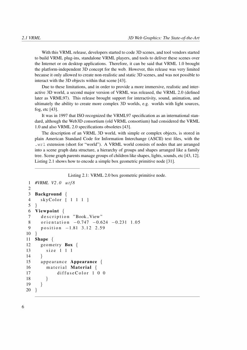
The description of an VRML 3D world, with simple or complex objects, is stored inplain American Standard Code for Information Interchange (ASCII) text files, with the.wrl extension (short for “world”). A VRML world consists of nodes that are arrangedinto a scene graph data structure, a hierarchy of groups and shapes arranged like a familytree. Scene graph parents manage groups of children like shapes, lights, sounds, etc [43, 12].Listing 2.1 shows how to encode a simple box geometric primitive node [31].
Listing 2.1: VRML 2.0 box geometric primitive node.
1 #VRML V2 . 0 u t f 823 Background {4 s k y C o lo r [ 1 1 1 ]5 }6 Viewpoint {7 d e s c r i p t i o n ”Book View”8 o r i e n t a t i o n −0.747 −0.624 −0.231 1 . 0 59 p o s i t i o n −1.81 3 . 1 2 2 . 5 9
10 }11 Shape {12 geomet ry Box {13 s i z e 1 1 114 }15 a p p e a r a n c e Appearance {16 m a t e r i a l Mater ia l {17 d i f f u s e C o l o r 1 0 018 }19 }20 }
6
3D Web Graphics: The State-of-the-Art 2.1 VRML
In order to display, interact, and navigate on the VRML 3D world described in the .wrlfile, we must use a VRML web browser plug-in or a standalone player to interpret thisfile. The .wrl file is parsed by the installed VRML web browser plug-in (player), and the3D contents are rendered into the browser window [31]. VRML players use 3D graphicsengines like OpenGL or DirectX to take advantage of the 3D graphics card in the clientcomputer.
Listing 2.2 shows how to embed a VRML file within a web page, usually index.html.Notice that the VRML Box.wrl file must be in the same directory as the index.htmlfile.
Listing 2.2: VRML file included in a web page through the HTML tag EMBED .
1 <html>2 <head>3 < t i t l e>VRML 2 . 0 Box g e o m e t r i c p r i m i t i v e node< / t i t l e>4 < / head>5 <body>6 <embed s r c =”Box . wr l ” width=” 300 ” h e i g h t =” 250 ”>7 < / body>8 < / html>
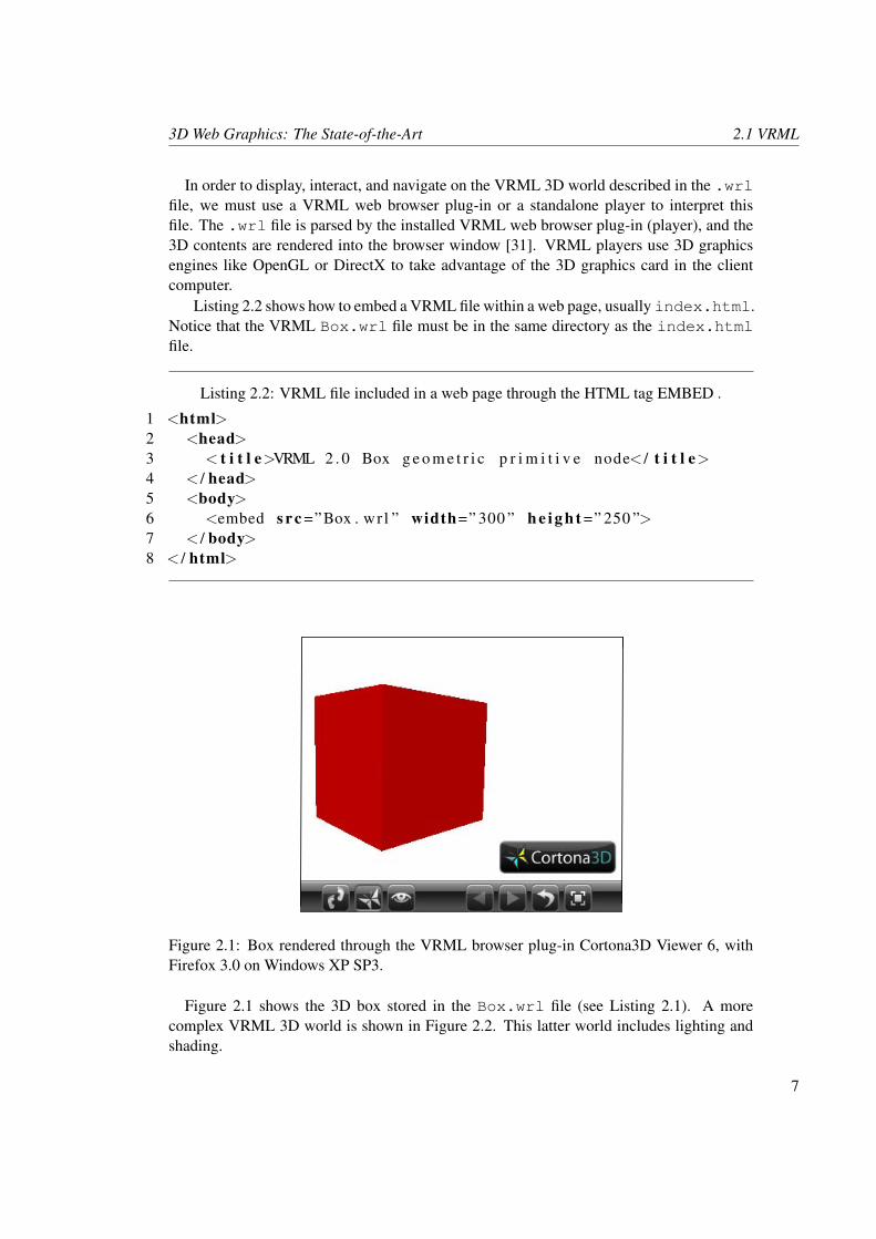
Figure 2.1: Box rendered through the VRML browser plug-in Cortona3D Viewer 6, withFirefox 3.0 on Windows XP SP3.
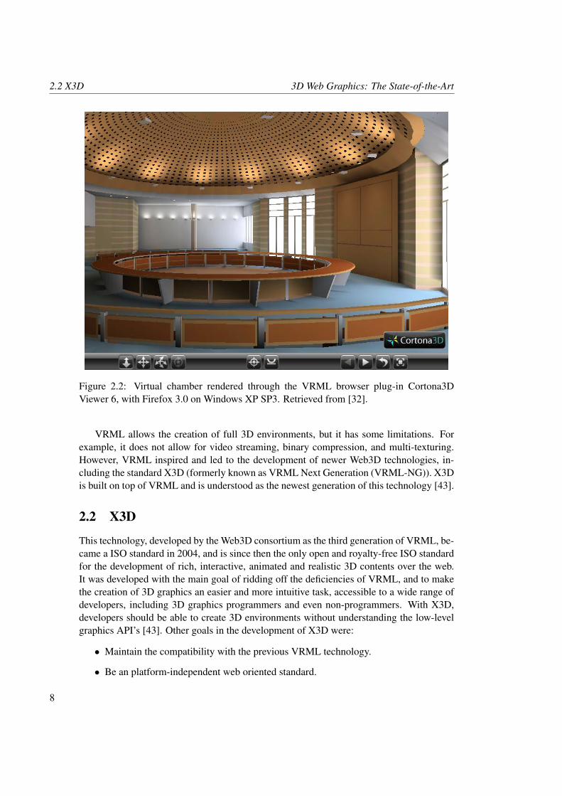
Figure 2.1 shows the 3D box stored in the Box.wrl file (see Listing 2.1). A morecomplex VRML 3D world is shown in Figure 2.2. This latter world includes lighting andshading.
7
2.2 X3D 3D Web Graphics: The State-of-the-Art
Figure 2.2: Virtual chamber rendered through the VRML browser plug-in Cortona3DViewer 6, with Firefox 3.0 on Windows XP SP3. Retrieved from [32].
VRML allows the creation of full 3D environments, but it has some limitations. Forexample, it does not allow for video streaming, binary compression, and multi-texturing.However, VRML inspired and led to the development of newer Web3D technologies, in-cluding the standard X3D (formerly known as VRML Next Generation (VRML-NG)). X3Dis built on top of VRML and is understood as the newest generation of this technology [43].
2.2 X3D
This technology, developed by the Web3D consortium as the third generation of VRML, be-came a ISO standard in 2004, and is since then the only open and royalty-free ISO standardfor the development of rich, interactive, animated and realistic 3D contents over the web.It was developed with the main goal of ridding off the deficiencies of VRML, and to makethe creation of 3D graphics an easier and more intuitive task, accessible to a wide range ofdevelopers, including 3D graphics programmers and even non-programmers. With X3D,developers should be able to create 3D environments without understanding the low-levelgraphics API’s [43]. Other goals in the development of X3D were:
• Maintain the compatibility with the previous VRML technology.
• Be an platform-independent web oriented standard.
8
3D Web Graphics: The State-of-the-Art 2.2 X3D
To fulfill these goals, X3D defined three equivalent encoding formats: a classic VRMLversion, an XML-based version, and a compressed binary version to encode X3D scenefiles.
The classic VRML encoding maintains the same structure as the one of VRML97. TheXML encoding allows that the X3D contents can be used by a broader audience, devicesand applications, on different platforms across the web. Finally, the compressed binaryencoding makes the file size smaller, and increases the parsing speed, the transmission, andthe loading times [10, 26].
With the XML encoding, X3D allows developers to create and manipulate 3D contentsusing only XML tags, as opposed to the classic VRML encoding or VRML97, which requirea specific knowledge of the language to create 3D contents.
To encode information in an X3D scene, we can use the XML encoding file format.x3d or the classic VRML encoding file format .x3dv. Notice that the classic VRMLencoding has the same syntax as VRML97, with only two differences: the classic VRMLencoding supports X3D nodes, and the first line header changes from VRML V2.0 utf 8to X3D V3.1 utf 8 (compare headers from Listings 2.1 and 2.3). The binary encodingfile format .x3db, just compresses any X3D scene (.x3d, .x3dv or even .wrl) forfaster scene loading at run time and network streaming, and adds (if desired) XML securityfor content protection. Listing 2.3, with the classic VRML encoding, and Listing 2.4, withthe XML encoding, show the commands necessary to create the same box of Figure 2.1[9, 10].
Embedding an X3D file within a web page is done just like in VRML (Listing 2.2).
Listing 2.3: Classic VRML (.x3dv) encoding.1 #X3D V3 . 1 u t f 82 Background {3 s k y C o l o r [ 1 1 1 ]4 }5 Viewpoint {6 d e s c r i p t i o n ”Book View”7 o r i e n t a t i o n −0.747 −0.624 −0.231 1 . 0 58 p o s i t i o n −1.81 3 . 1 2 2 . 5 99 }
10 Shape {11 geomet ry Box {12 s i z e 1 1 113 }14 a p p e a r a n c e Appearance {15 m a t e r i a l Mater ia l {16 d i f f u s e C o l o r 1 0 017 }18 }19 }
9
2.2 X3D 3D Web Graphics: The State-of-the-Art
Listing 2.4: XML (.x3d) encoding.
1 <? xml v e r s i o n =” 1 . 0 ” e n c o d i n g =”UTF−8” ?>2 <!DOCTYPE X3D PUBLIC ” ISO / / Web3D / / DTD X3D 3 . 1 / / EN”3 ” h t t p : / /www. web3d . o rg / s p e c i f i c a t i o n s / x3d −3 .1 . d t d ”>4 <X3D p r o f i l e = ’ I n t e r c h a n g e ’ v e r s i o n = ’ 3 . 1 ’ x m l n s : x s d =5 ’ h t t p : / /www. w3 . org / 2 0 0 1 / XMLSchema−i n s t a n c e ’6 xsd :noNamespaceSchemaLoca t ion = ’ h t t p : / /www. web3d . o rg /7 s p e c i f i c a t i o n s / x3d −3 .1 . xsd ’>8 <Scene>9 <Background s k y Co l o r = ’ 1 1 1 ’ />
10 <Viewpoin t d e s c r i p t i o n = ’ Book View ’ o r i e n t a t i o n =11 ’−0.747 −0.624 −0.231 1 . 0 5 ’ p o s i t i o n = ’−1.81 3 . 1 2 2 . 5 9 ’ />12 <Shape>13 <Box s i z e = ’ 1 1 1 ’ />14 <Appearance>15 <M a t e r i a l d i f f u s e C o l o r = ’ 1 0 0 ’ />16 < / Appearance>17 < / Shape>18 < / Scene>19 < /X3D>
X3D uses a tree-structured scene graph to represent the graphics nodes that make part ofthe 3D world. This scene graph includes the geometry, appearance, animation and eventrouting. In addition to the geometry and animation behaviors expressed in XML, X3Dallows scripting (mainly through JavaScript programming) and node prototyping, that to-gether provide support for scene graph extensions, like complex animations and user in-teractions. Other advanced X3D functionalities, that VRML does not support, are multi-texturing surfaces, Non-Uniform Rational Bezier Spline (NURBS) parametric surfaces,geospatial positioning, interchangeable Humanoid Animation (H-Anim) bodies, and theIEEE Distributed Interactive Simulation (DIS) network protocol [9, 10, 12].
Just like VRML, X3D needs a player to parse and render an encoded X3D scene, whichmay also allows for user interaction and object animation. In fact, every browser needs aX3D player plug-in in order to render X3D scenes. These players can also be delivered asstandalone or desktop applications. For a full description of the available VRML and X3Dplayers see Appendix B. Figure 2.3 shows the architecture of an X3D player.
An X3D player has parsers that read the X3D files formats encodings. After that, thenodes are created and sent to the scene graph manager, which is responsible to managethe geometry, appearance, location and orientation of objects. Then, the scene graph isrendered. On the other hand, the event graph is responsible of all animation nodes. Theseanimations can be extended or enhanced through scripting languages like JavaScript. TheScene Authoring Interface (SAI) enables that an application external to the X3D player canperform operations inside the X3D scene during run time. HTML web pages or externalapplications can embed X3D players to display and interact with the 3D objects [9, 10].
10
3D Web Graphics: The State-of-the-Art 2.2 X3D
X3D PLAYER
X3D scenes, X3D streams
Parsers
X3D XML encoding
Classic VRML encoding
Binary encoding
New node and prototype construction
X3D nodes, node types
Prototype and External Prototype
Scene graph manager
Scene Authoring Interface (SAI)Application programmer interfaces
Scripting Engines:
ECMAScriptJava
Others
Scene Graph Renderable Nodes Event Graph Animation Nodes
HTML web page or External
application
Figure 2.3: X3D player architecture. On the left, file parsing and rendering process. On theright, animation and scene graph manipulation. Image based on the model from the book[9]).
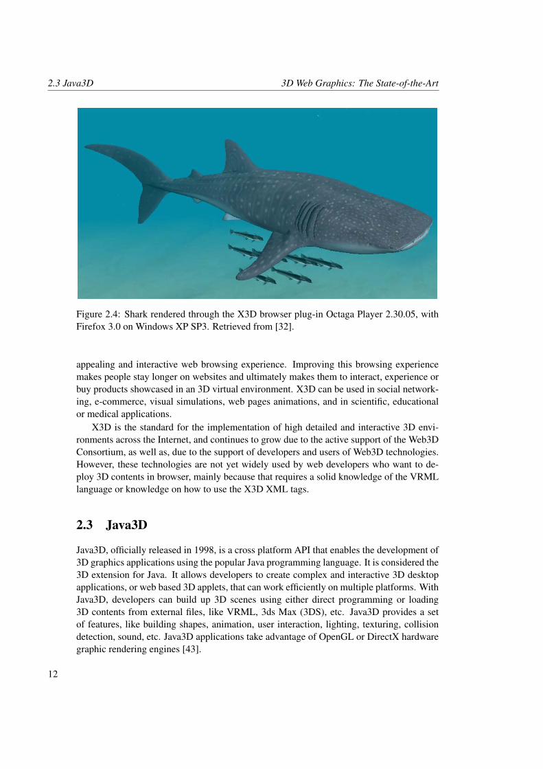
Most of 3D players use the low level OpenGL or DirectX rendering engines to render thegraphical content. When hardware graphics acceleration is not available we use an softwarerenderer instead. When choosing VRML and X3D players, developers must choose theone compatible with their operating system and browser version. Another aspect to takeinto account is whether or not a X3D player is proprietary or open source and royality-free. Even with the many resources, repositories, and material available to facilitate theconstruction of X3D worlds, this can become a complex task when creating complex andhigh detailed X3D scenes. So, to help creating X3D worlds, a variety of authoring tools canbe used (see Appendix B). In Figure 2.4 is shown a high detailed X3D world.
The purpose of building X3D worlds, especially for the web, is to provide a better, more
11
2.3 Java3D 3D Web Graphics: The State-of-the-Art
Figure 2.4: Shark rendered through the X3D browser plug-in Octaga Player 2.30.05, withFirefox 3.0 on Windows XP SP3. Retrieved from [32].
appealing and interactive web browsing experience. Improving this browsing experiencemakes people stay longer on websites and ultimately makes them to interact, experience orbuy products showcased in an 3D virtual environment. X3D can be used in social network-ing, e-commerce, visual simulations, web pages animations, and in scientific, educationalor medical applications.
X3D is the standard for the implementation of high detailed and interactive 3D envi-ronments across the Internet, and continues to grow due to the active support of the Web3DConsortium, as well as, due to the support of developers and users of Web3D technologies.However, these technologies are not yet widely used by web developers who want to de-ploy 3D contents in browser, mainly because that requires a solid knowledge of the VRMLlanguage or knowledge on how to use the X3D XML tags.
2.3 Java3D
Java3D, officially released in 1998, is a cross platform API that enables the development of3D graphics applications using the popular Java programming language. It is considered the3D extension for Java. It allows developers to create complex and interactive 3D desktopapplications, or web based 3D applets, that can work efficiently on multiple platforms. WithJava3D, developers can build up 3D scenes using either direct programming or loading3D contents from external files, like VRML, 3ds Max (3DS), etc. Java3D provides a setof features, like building shapes, animation, user interaction, lighting, texturing, collisiondetection, sound, etc. Java3D applications take advantage of OpenGL or DirectX hardwaregraphic rendering engines [43].
12
3D Web Graphics: The State-of-the-Art 2.3 Java3D
As opposed to VRML, that is an human readable 3D content development language,stored in plain ASCII text files, that are interpreted by VRML players, and unlike X3D, thatcan use classic VRML, XML or a compressed binary version to encode X3D scenes, alsointerpreted by X3D players, Java3D is an extension to Java. It is a fully high-level 3D API.Java3D source code is only human readable while being written. The source code is thencompiled into a platform-independent Java byte-code format that, as an intermediary formof code (not human readable and not binary machine code), provides the platform indepen-dence. This Java byte-code format must pass through a Java Virtual Machine (JVM), on theclient side, to be converted into machine code in order to be executed. Because this con-version occurs at runtime, the Java byte-code can be executed in any platform, as long as aJVM is installed to allow the conversion and execution of the Java3D application. Becausethe Java byte-code format can be converted to machine code faster than the ASCII text ofVRML files, in part due to its proximity to the machine code, Java3D applications end upto be executed faster than VRML applications [43].
Despite the mentioned differences, Java3D has some similar aspects with VRML andX3D. In fact, the Java3D API encapsulates the low level 3D details, allowing developers,even those without experience in 3D programming, to develop 3D applications. As saidearlier, Java3D can load, among others, VRML files, allowing users to take advantage ofthe existing VRML models. Also like VRML and X3D, Java3D uses a tree-structured scenegraph programming model, to store, organize and render all the components of an 3D scene.Java3D is also a royalty-free technology [43].
To use Java3D, their classes have to be downloaded separately from the standard Javadistribution. This is to avoid a multiple set of options, that might be unnecessary for someusers, in the standard Java distribution. After writing or downloading the source code of anJava3D application, a Java3D applet must be embedded within a web page, in order to runsuch application within that web page. This embedding process is illustrated in Listing 2.5.Notice that the class file HelloJava3Dd.class must be in the same directory as theone of the html file where is included.
Listing 2.5: Applet included in a web page through the HTML tag APPLET .
1 <html>2 <head>3 < t i t l e>Hel loJava3Dd . j a v a example< / t i t l e>4 < / head>5 <body>6 <a p p l e t code=” Hel loJava3Dd . c l a s s ” width=” 300 ”7 h e i g h t =” 300 ”>8 < / a p p l e t>9 < / body>
10 < / html>
To run the applet, the Java plug-in must be installed first to enable its execution underthe Java Runtime Environment (JRE) within the browser. Installing the JRE on a computer
13
2.3 Java3D 3D Web Graphics: The State-of-the-Art
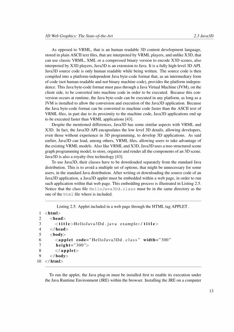
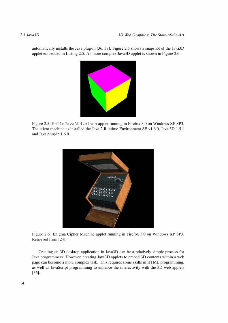
automatically installs the Java plug-in [36, 37]. Figure 2.5 shows a snapshot of the Java3Dapplet embedded in Listing 2.5. An more complex Java3D applet is shown in Figure 2.6.
Figure 2.5: HelloJava3Dd.class applet running in Firefox 3.0 on Windows XP SP3.The client machine as installed the Java 2 Runtime Environment SE v1.6.0, Java 3D 1.5.1and Java plug-in 1.6.0.
Figure 2.6: Enigma Cipher Machine applet running in Firefox 3.0 on Windows XP SP3.Retrieved from [24].
Creating an 3D desktop application in Java3D can be a relatively simple process forJava programmers. However, creating Java3D applets to embed 3D contents within a webpage can become a more complex task. This requires some skills in HTML programming,as well as JavaScript programming to enhance the interactivity with the 3D web applets[36].
14
3D Web Graphics: The State-of-the-Art 2.4 Flash 3D
2.4 Flash 3D
The Adobe Flash Player is one of the most, if not the most, popular platforms to createinteractive and visually outstanding 2D and/or 3D text, animations, web games, Rich In-ternet Applications (RIA), and websites for the web. Usually, in the development of Flashapplications, we use the Adobe ActionScript language. This scripting language, created byMacromedia (now owned by Adobe Systems) in 1998, is based on ECMAScript (the samestandard for JavaScript), and can be used for enhancing and complementing the functionali-ties of the Flash Player, in the same way that JavaScript enhances and complements HTML[4, 1].
In the earlier releases of the Flash Player (still from Macromedia), only some buttonactions and mouse interactions (through action scripting) were available, but with the releaseof Macromedia Flash Player 5 and with the introduction of ActionScript 1, more actionsto provide better interactivity became available. It was in this Flash Player release thatthe ActionScript language took a JavaScript-like form, becoming a prototyped language,which allowed simple object-oriented functionalities. ActionScript 2.0 was introduced inMacromedia Flash MX 2004, or release 7 [4, 1].
This release brought two major improvements that allowed the creation of more com-plex actions: variable data typing and a new class syntax. With this two ActionScript re-leases was possible, for example, to create some complex 2D animations. ActionScript 1and 2 use the ActionScript Virtual Machine (AVM) version 1, that is the underlying softwarewithin the Flash Player that executes ActionScript during playback [4, 1].
After the acquisition of Macromedia by Adobe, Flash was integrated in the Adobe CS3package, and the ninth release of the Flash Player was released as Adobe Flash CS3, as wellas a new version of ActionScript. With ActionScript 3, a new AVM was created (AVM2).This virtual machine only execute ActionScript 3 code, and was developed to provide gainsin runtime performance and to improve developers productivity, providing resources for thecreation of RIAs with audio and video streaming, as well as web games. For enhancing theperformance speed, AVM2 includes a Just In Time compiler (JIT) that translates Action-Script byte-code to native machine code. ActionScript 3 introduced hardware acellerationthrough DirectX or OpenGL to speed up the running process of Flash in browser [4, 1].
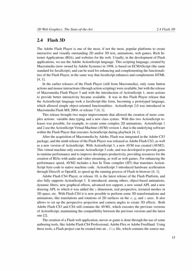
Adobe Flash CS4 Player, or release 10, is the latest release of the Flash Platform, andalso fully supports ActionScript 3. It introduced, among others, object-based animations,dynamic filters, new graphical effects, advanced text support, a new sound API, and a newdrawing API, to which it was added the z dimension, real perspective, textured meshes in3D space, etc. With Flash CS4 it is now possible to perform some 3D transformations andanimations, like translations and rotations of 2D surfaces on the x, y, and z axes. It alsoallows to set up the perspective projection and camera angles to create 3D effects. BothAdobe Flash CS3 and CS4 still contains the AVM1, which executes the previous versionsof ActionScript, maintaining the compatibility between the previous versions and the latestone [2].
The creation of a Flash web application, movie or game is done through the use of someauthoring tools, like Adobe Flash CS4 Professional, Adobe Flex or Adobe FreeHand. Usingthese tools, a Flash project can be created into an .fla file, which contains the source ma-
15
2.4 Flash 3D 3D Web Graphics: The State-of-the-Art
terial of the Flash application. ActionScript enhancements can also be created and appliedto this project using an .as file. Terminated a project, the .fla file is compiled into anon-editable and final .swf file. This file is ready to be manipulated, played or visualizedthrough the Adobe Flash Player web browser plug-in. Originally .swf was the shorthandof “Shockwave Flash”, but now stands for “Small Web Format”. Today, a Shockwave fileformat has the .dcr extension and is generated by the Adobe Director authoring applica-tion. Shockwave aims at creating more complex web and multimedia applications, whileFlash is used for the creation of visually appealing and interactive web interfaces, as well asweb games. To interact and display a Shockwave application we use the Adobe ShockwavePlayer [5]. Embedding a Flash file within a web page is shown in Listing 2.6. Figure 2.7shows the result of the Flash CS4 .swf file embedded in Listing 2.6.
Listing 2.6: Flash CS4 .swf file embedded in a web page through the HTML tag OBJECT.
1 <html>2 <head>3 < t i t l e>F l a s h CS4 3D Cube< / t i t l e>4 < / head>5 <body>67 <o b j e c t data=” c s 4 s i m p l e 3 d c u b e . swf ”8 type =” a p p l i c a t i o n / x−shockwave−f l a s h ” width=” 640 ”9 h e i g h t =” 440 ”>
10 <param value =” c s 4 s i m p l e 3 d c u b e . swf ” />11 < / o b j e c t>1213 < / body>14 < / html>
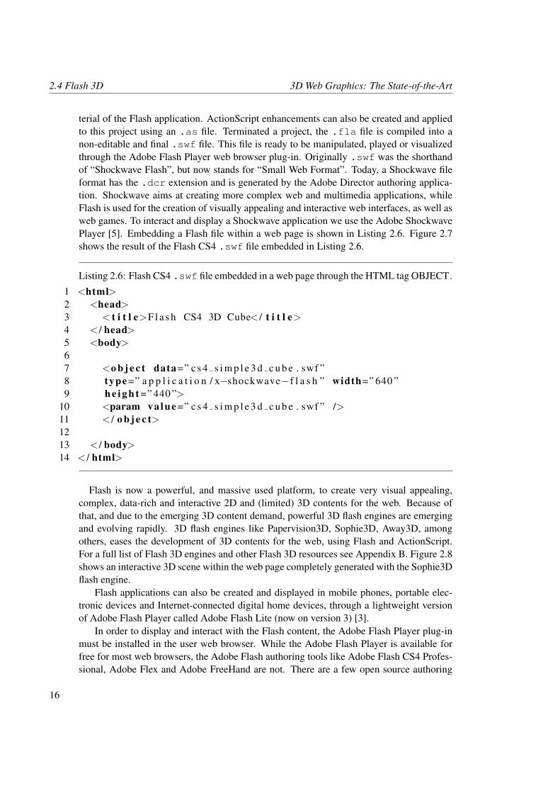
Flash is now a powerful, and massive used platform, to create very visual appealing,complex, data-rich and interactive 2D and (limited) 3D contents for the web. Because ofthat, and due to the emerging 3D content demand, powerful 3D flash engines are emergingand evolving rapidly. 3D flash engines like Papervision3D, Sophie3D, Away3D, amongothers, eases the development of 3D contents for the web, using Flash and ActionScript.For a full list of Flash 3D engines and other Flash 3D resources see Appendix B. Figure 2.8shows an interactive 3D scene within the web page completely generated with the Sophie3Dflash engine.
Flash applications can also be created and displayed in mobile phones, portable elec-tronic devices and Internet-connected digital home devices, through a lightweight versionof Adobe Flash Player called Adobe Flash Lite (now on version 3) [3].
In order to display and interact with the Flash content, the Adobe Flash Player plug-inmust be installed in the user web browser. While the Adobe Flash Player is available forfree for most web browsers, the Adobe Flash authoring tools like Adobe Flash CS4 Profes-sional, Adobe Flex and Adobe FreeHand are not. There are a few open source authoring
16
3D Web Graphics: The State-of-the-Art 2.4 Flash 3D
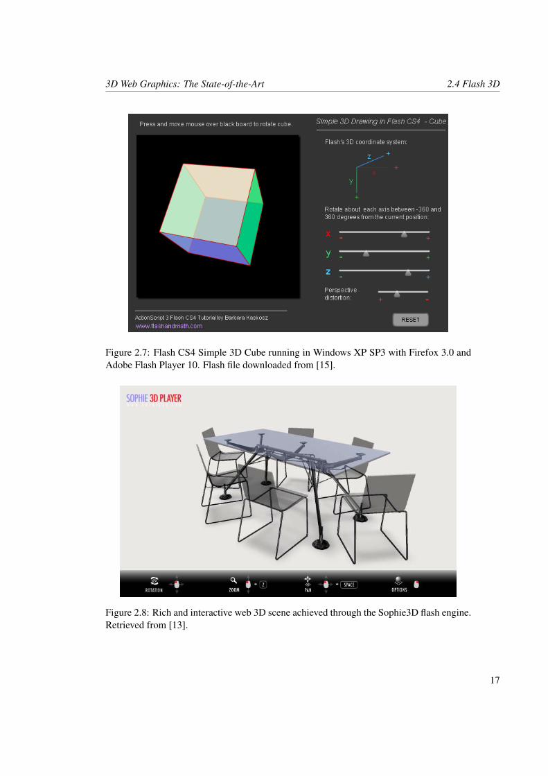
Figure 2.7: Flash CS4 Simple 3D Cube running in Windows XP SP3 with Firefox 3.0 andAdobe Flash Player 10. Flash file downloaded from [15].
Figure 2.8: Rich and interactive web 3D scene achieved through the Sophie3D flash engine.Retrieved from [13].
17
2.5 C3DL 3D Web Graphics: The State-of-the-Art
tools to develop Flash, but developers are forced to use the Adobe proprietary tools if theywant to take full advantage of all the Flash functionalities. Flash, with its new drawingAPI, tries to involve non-3D developers in the creation of 3D contents, by allowing the de-signing in 2D and the transformation and animation in 3D. However, to create 3D contents,developers must have a solid knowledge of Flash and ActionScript. Like VRML, X3D andJava3D, Flash 3D tries to facilitate the development of 3D contents for the web, and usesa web browser plug-in for the display and interaction with these contents. But, unlike thementioned Web3D technologies, where exists a variety of free authoring tools, Flash3Drequires the use of proprietary tools to create 3D web applications. Besides, it may be adifficult development platform to use for 3D non-developers.
2.5 C3DL
The C3DL has been under development since 2007, and is an open source Web3D graphicslibrary written in JavaScript that allows the creation of 3D contents in browser. It has beendeveloped with the purpose of simplifying the creation and manipulation of 3D contents.For that, it provides a set of math, scene, and 3D objects classes to developers with little 3Dprogramming experience. This library is built on top of the Mozilla Firefox Canvas 3D add-on. This add-on (browser specific and still experimental), provides the low level renderingfunctionality to C3DL, through the HTML5 canvas element (discussed in detail in Chapter3) and an OpenGL ES 2.0 API-based rendering context written in JavaScript, allowing thedisplay of 3D scenes and 3D objects within an area of an web page, defined by the canvastag [27, 8].
As said before, the Canvas 3D add-on provides access to an OpenGL ES 2.0 API-basedrendering context via the HTML5 canvas element. This context is called “moz-glweb20”and is a simplified and web oriented set of OpenGL ES 2.0 API-based functions. Becausethe “moz-glweb20” context is built on top of desktop OpenGL, users should have supportfor OpenGL 2.0 on the desktop if they want to take full advantage of C3DL [41, 39].
Initially, the Canvas 3D add-on provided both an OpenGL ES 1.1-based context (“moz-gles11”) and an OpenGL ES 2.0-based context (“moz-glweb20”), but due to the quick adop-tion of OpenGL ES 2.0 by mobile devices, and due to the complexity on maintaining the“moz-gles11” context, the currently supported context available is the “moz-glweb20” [40].
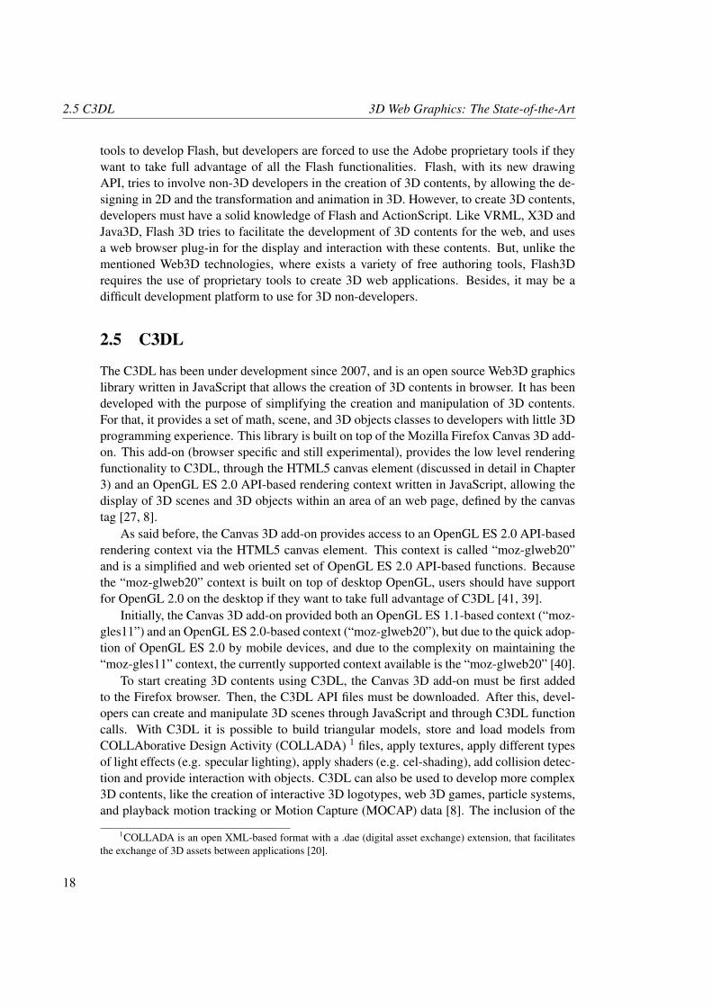
To start creating 3D contents using C3DL, the Canvas 3D add-on must be first addedto the Firefox browser. Then, the C3DL API files must be downloaded. After this, devel-opers can create and manipulate 3D scenes through JavaScript and through C3DL functioncalls. With C3DL it is possible to build triangular models, store and load models fromCOLLAborative Design Activity (COLLADA) 1 files, apply textures, apply different typesof light effects (e.g. specular lighting), apply shaders (e.g. cel-shading), add collision detec-tion and provide interaction with objects. C3DL can also be used to develop more complex3D contents, like the creation of interactive 3D logotypes, web 3D games, particle systems,and playback motion tracking or Motion Capture (MOCAP) data [8]. The inclusion of the
1COLLADA is an open XML-based format with a .dae (digital asset exchange) extension, that facilitatesthe exchange of 3D assets between applications [20].
18
3D Web Graphics: The State-of-the-Art 2.5 C3DL
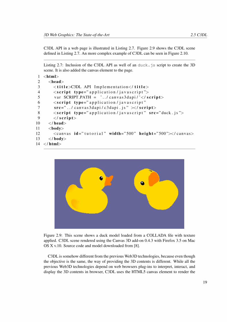
C3DL API in a web page is illustrated in Listing 2.7. Figure 2.9 shows the C3DL scenedefined in Listing 2.7. An more complex example of C3DL can be seen in Figure 2.10.
Listing 2.7: Inclusion of the C3DL API as well of an duck.js script to create the 3Dscene. It is also added the canvas element to the page.
1 <html>2 <head>3 < t i t l e>C3DL API I m p l e m e n t a t i o n< / t i t l e>4 <s c r i p t type =” a p p l i c a t i o n / j a v a s c r i p t ”>5 v a r SCRIPT PATH = ’ . . / c a n v a s 3 d a p i / ’< / s c r i p t>6 <s c r i p t type =” a p p l i c a t i o n / j a v a s c r i p t ”7 s r c =” . . / c a n v a s 3 d a p i / c 3 d a p i . j s ” >< / s c r i p t>8 <s c r i p t type =” a p p l i c a t i o n / j a v a s c r i p t ” s r c =” duck . j s ”>9 < / s c r i p t>
10 < / head>11 <body>12 <c an va s id =” t u t o r i a l ” width=” 500 ” h e i g h t =” 500 ”>< / c a nv as>13 < / body>14 < / html>
Figure 2.9: This scene shows a duck model loaded from a COLLADA file with textureapplied. C3DL scene rendered using the Canvas 3D add-on 0.4.3 with Firefox 3.5 on MacOS X v.10. Source code and model downloaded from [8].
C3DL is somehow different from the previous Web3D technologies, because even thoughthe objective is the same, the way of providing the 3D contents is different. While all theprevious Web3D technologies depend on web browsers plug-ins to interpret, interact, anddisplay the 3D contents in browser, C3DL uses the HTML5 canvas element to render the
19
2.6 Other Web3D Technologies 3D Web Graphics: The State-of-the-Art
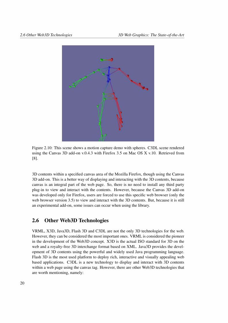
Figure 2.10: This scene shows a motion capture demo with spheres. C3DL scene renderedusing the Canvas 3D add-on v.0.4.3 with Firefox 3.5 on Mac OS X v.10. Retrieved from[8].
3D contents within a specified canvas area of the Mozilla Firefox, though using the Canvas3D add-on. This is a better way of displaying and interacting with the 3D contents, becausecanvas is an integral part of the web page. So, there is no need to install any third partyplug-in to view and interact with the contents. However, because the Canvas 3D add-onwas developed only for Firefox, users are forced to use this specific web browser (only theweb browser version 3.5) to view and interact with the 3D contents. But, because it is stillan experimental add-on, some issues can occur when using the library.
2.6 Other Web3D Technologies
VRML, X3D, Java3D, Flash 3D and C3DL are not the only 3D technologies for the web.However, they can be considered the most important ones. VRML is considered the pioneerin the development of the Web3D concept. X3D is the actual ISO standard for 3D on theweb and a royalty-free 3D interchange format based on XML. Java3D provides the devel-opment of 3D contents using the powerful and widely used Java programming language.Flash 3D is the most used platform to deploy rich, interactive and visually appealing webbased applications. C3DL is a new technology to display and interact with 3D contentswithin a web page using the canvas tag. However, there are other Web3D technologies thatare worth mentioning, namely:
20
3D Web Graphics: The State-of-the-Art 2.6 Other Web3D Technologies
2.6.1 Ajax3D
Ajax3D stands for Asynchronous JavaScript and XML for the development of 3D contentsfor the web. To allow the creation of 3D web contents, it combines Ajax with X3D. Ajaxallows the development of rapid, dynamic, interactive and rich web applications, while X3Dprovides the Scene Authoring Interface (SAI), the API that controls an X3D scene [34].
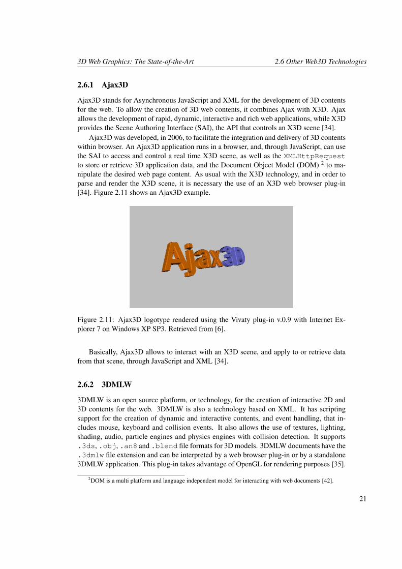
Ajax3D was developed, in 2006, to facilitate the integration and delivery of 3D contentswithin browser. An Ajax3D application runs in a browser, and, through JavaScript, can usethe SAI to access and control a real time X3D scene, as well as the XMLHttpRequestto store or retrieve 3D application data, and the Document Object Model (DOM) 2 to ma-nipulate the desired web page content. As usual with the X3D technology, and in order toparse and render the X3D scene, it is necessary the use of an X3D web browser plug-in[34]. Figure 2.11 shows an Ajax3D example.
Figure 2.11: Ajax3D logotype rendered using the Vivaty plug-in v.0.9 with Internet Ex-plorer 7 on Windows XP SP3. Retrieved from [6].
Basically, Ajax3D allows to interact with an X3D scene, and apply to or retrieve datafrom that scene, through JavaScript and XML [34].
2.6.2 3DMLW
3DMLW is an open source platform, or technology, for the creation of interactive 2D and3D contents for the web. 3DMLW is also a technology based on XML. It has scriptingsupport for the creation of dynamic and interactive contents, and event handling, that in-cludes mouse, keyboard and collision events. It also allows the use of textures, lighting,shading, audio, particle engines and physics engines with collision detection. It supports.3ds, .obj, .an8 and .blend file formats for 3D models. 3DMLW documents have the.3dmlw file extension and can be interpreted by a web browser plug-in or by a standalone3DMLW application. This plug-in takes advantage of OpenGL for rendering purposes [35].
2DOM is a multi platform and language independent model for interacting with web documents [42].
21
2.6 Other Web3D Technologies 3D Web Graphics: The State-of-the-Art
3DMLW has been evolving to become a cross platform and cross browser compatibletechnology. By now, it is fully functional for Firefox, Safari, Opera, Chrome and InternetExplorer browsers, and for Microsoft Windows applications. The Mac OS X and Linuxdistributions are in beta versions and still cause problems.
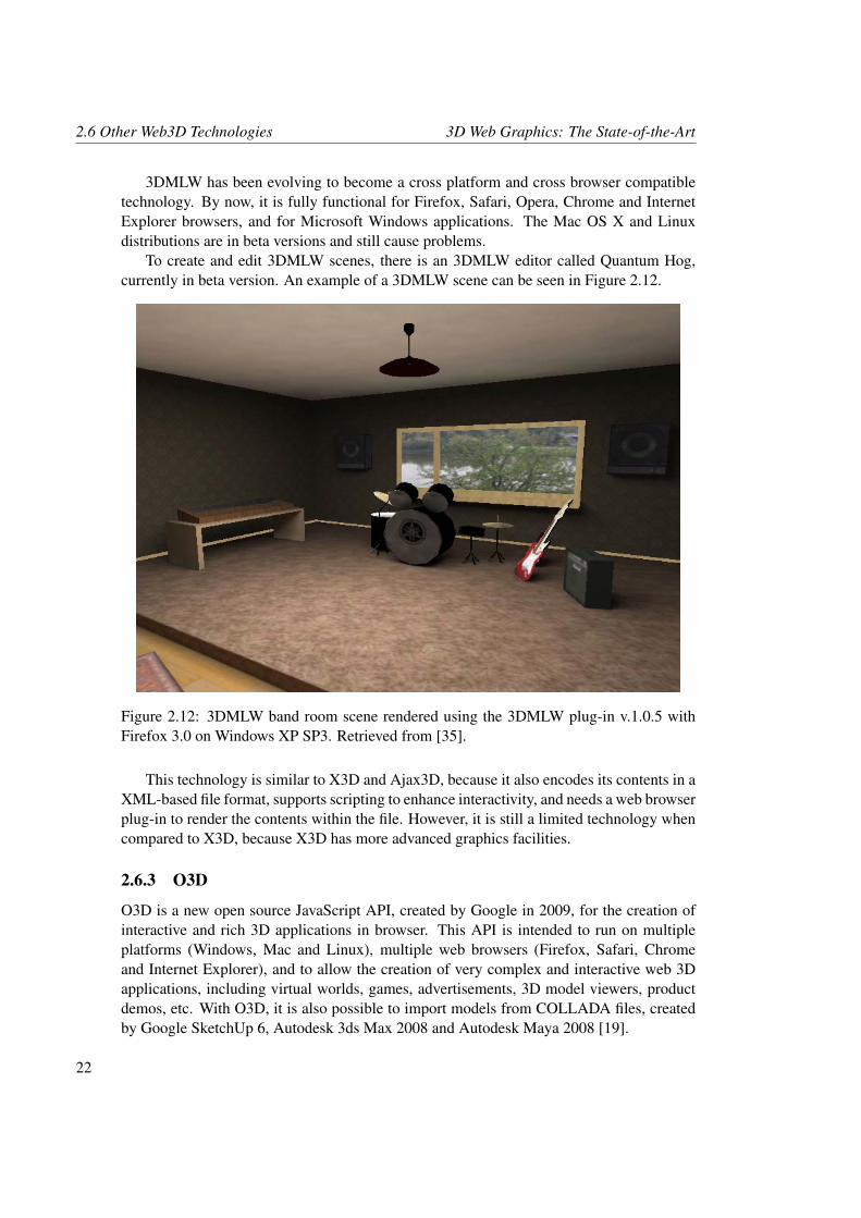
To create and edit 3DMLW scenes, there is an 3DMLW editor called Quantum Hog,currently in beta version. An example of a 3DMLW scene can be seen in Figure 2.12.
Figure 2.12: 3DMLW band room scene rendered using the 3DMLW plug-in v.1.0.5 withFirefox 3.0 on Windows XP SP3. Retrieved from [35].
This technology is similar to X3D and Ajax3D, because it also encodes its contents in aXML-based file format, supports scripting to enhance interactivity, and needs a web browserplug-in to render the contents within the file. However, it is still a limited technology whencompared to X3D, because X3D has more advanced graphics facilities.
2.6.3 O3D
O3D is a new open source JavaScript API, created by Google in 2009, for the creation ofinteractive and rich 3D applications in browser. This API is intended to run on multipleplatforms (Windows, Mac and Linux), multiple web browsers (Firefox, Safari, Chromeand Internet Explorer), and to allow the creation of very complex and interactive web 3Dapplications, including virtual worlds, games, advertisements, 3D model viewers, productdemos, etc. With O3D, it is also possible to import models from COLLADA files, createdby Google SketchUp 6, Autodesk 3ds Max 2008 and Autodesk Maya 2008 [19].
22
3D Web Graphics: The State-of-the-Art 2.7 Summary
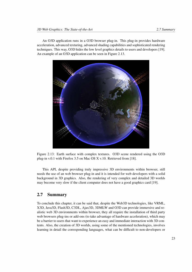
An O3D application runs in a O3D browser plug-in. This plug-in provides hardwareacceleration, advanced texturing, advanced shading capabilities and sophisticated renderingtechniques. This way, O3D hides the low level graphics details to users and developers [19].An example of an O3D application can be seen in Figure 2.13.
Figure 2.13: Earth surface with complex textures. O3D scene rendered using the O3Dplug-in v.0.1 with Firefox 3.5 on Mac OS X v.10. Retrieved from [18].
This API, despite providing truly impressive 3D environments within browser, stillneeds the use of an web browser plug-in and it is intended for web developers with a solidbackground in 3D graphics. Also, the rendering of very complex and detailed 3D worldsmay become very slow if the client computer does not have a good graphics card [19].
2.7 Summary
To conclude this chapter, it can be said that, despite the Web3D technologies, like VRML,X3D, Java3D, Flash3D, C3DL, Ajax3D, 3DMLW and O3D can provide immersive and re-alistic web 3D environments within browser, they all require the installation of third partyweb browsers plug-ins or add-ons (to take advantage of hardware acceleration), which maybe a barrier to users that want to experience an easy and immediate interaction with 3D con-tents. Also, the creation of 3D worlds, using some of the mentioned technologies, involveslearning in detail the corresponding languages, what can be difficult to non-developers or
23
2.7 Summary 3D Web Graphics: The State-of-the-Art
even to web developers (see Appendix B for additional information about all the mentionedWeb3D technologies). So, Glypher3D can become a useful technology to render 3D con-tents over the web, because it does not need the installation of any web browser plug-in oradd-on. The fact that it is fully encoded in JavaScript, makes it more accessible to learn fornon-developers and especially to web developers. However, it does not take advantage ofhardware acceleration. Consequently, it cannot provide the level of realism and renderingspeed of other Web3D technologies yet. Glypher3D only uses HTML specifications andJavaScript to provide the creation, manipulation and rendering of 3D contents within a webpage. Glypher3D will be described in detail in Chapter 3.
24
Chapter 3
Glypher3D
Glypher3D is an open source Web3D API, entirely written in JavaScript, that aims at en-abling the creation, manipulation and rendering of 3D contents within a web browser, with-out the need for installing any type of web browser plug-in or add-on. For that, we usethe HTML5 canvas element together with 3D graphics algorithms encoded in JavaScript.Glypher3D attempts to provide a more intuitive way to develop and interact with the 3Dcontents using only JavaScript. It is a multi-platform and cross browser compatible librarythat runs on Windows, Mac and Linux, and within most browsers like Firefox (3+), Sa-fari (4+), Opera (10+) and Chrome (2+). Its main drawback is the incompatibility withMicrosoft Internet Explorer, but this happens so because the Internet Explorer does notsupport the HTML5 canvas element (used for drawing and rendering purposes).
Glypher3D can be used to create 3D scenes with points, lines, triangular or quadrangularshapes. It also allows for shading effects (e.g. flat shading), geometric transformations(e.g. rotation on the x-axis), hidden surface removal algorithms (e.g. back-face culling),and projection transformations (e.g. perspective projection). Additionally, it allows forwireframe and color filling objects. With Glypher3D, every object has to be created fromscratch using JavaScript, because it does not allow us to import any 3D model in a specificformat file. Also, it does not support texturing.
3.1 The Canvas Element
As said before, the HTML5 canvas element is the essential technology for Glypher3D,because it allow us to create a rectangular area within the browser, where it is possible todraw 3D scenes, without the need for installing any browser plug-in or add-on.
Basically, the HTML5 canvas element is just a HTML element that can be used to draw2D graphics on its rendering context, and is normally used to make photo compositions,simple games, graphs, charts or animations. This element was introduced by Apple in itsMac OS X Dashboard, but it was soon adopted by the WebKit (Safari) and Gecko (Fire-fox) browsers. Currently, all browsers, except Internet Explorer, support this element. Thecanvas element is now part of the HTML5 specification [11, 23].
25
3.2 Client-Side Architecture Glypher3D
However, there are other technologies, like Scalable Vector Graphics (SVG), that canprovide graphics for the web. SVG is an XML markup language, as well as World WideWeb Consortium (W3C) standard, for describing 2D vector graphics. It allows to drawhigh quality graphics (shapes) through its graphics primitives specified by XML and it has ascene DOM, what makes event handling easy (interaction with objects, e.g. mouse events).However, it is somehow difficult to integrate with HTML, has a slower rendering perfor-mance, and the process of creating graphics is more complex than with the canvas element[38].
Therefore, what led to the choice of the canvas element to provide the drawing andrendering functions to the Glypher3D library was, mainly, the simpler, faster, practical,and immediate way to draw pixel-based graphics through its 2D API. Besides, the canvaselement is an integral element of the web page, which facilitates the access to its functionsthrough JavaScript, as needed for Glypher3D. This element has a few drawbacks, namelythe inexistence of a scene DOM (event handling harder) and, like SVG, it is not supportedby Internet Explorer. However, some efforts are being done to make the canvas elementaccessible for this browser, like the Google Internet Explorer plugin called ExplorerCanvas[17]. This plugin only translates canvas commands to Vector Markup Language (VML)(XML language to develop vector graphics for Internet Explorer), because it only supportssimple drawing functions and has a slower rendering process [38].
3.2 Client-Side Architecture
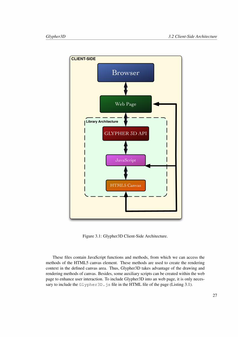
The Glypher3D architecture is illustrated in Figure 3.1. This architecture shows that Glypher-3D is a client-side JavaScript web library. This means that a client does not need to down-load it in order to run a Glypher3D application. If Glypher3D is included in a web page,this page, as well as all Glypher3D JavaScript files, are loaded, and run locally in the webbrowser of the client.
However, if web developers intend to create Glypher3D-based applications in their webpages, they must download the Glypher3D library. This library will be in a folder named“glypher3dlib”, which includes the following 10 JavaScript files:
• Glypher3D.js.
• Main.js.
• ContextRenderer.js.
• ShapePoints.js.
• Transformations.js.
• Perspectives.js.
• Illumination.js.
• ColorAndShading.js.
• DrawingPrimitives.js.
• UtilitiesAux.js.
26
Glypher3D 3.2 Client-Side Architecture
CLIENT-SIDE
Library Architecture
Browser
Web Page
JavaScript
HTML5 Canvas
GLYPHER 3D API
Figure 3.1: Glypher3D Client-Side Architecture.
These files contain JavaScript functions and methods, from which we can access themethods of the HTML5 canvas element. These methods are used to create the renderingcontext in the defined canvas area. Thus, Glypher3D takes advantage of the drawing andrendering methods of canvas. Besides, some auxiliary scripts can be created within the webpage to enhance user interaction. To include Glypher3D into an web page, it is only neces-sary to include the Glypher3D.js file in the HTML file of the page (Listing 3.1).
27
3.3 Rendering Pipeline Glypher3D
Listing 3.1: Inclusion of Glypher3D into a web page.
1 <head>2 <s c r i p t type =” t e x t / j a v a s c r i p t ”3 s r c =” g l y p h e r 3 d l i b / Glypher3D . j s ”>4 < / s c r i p t>5 < / head>
The inclusion of this JavaScript file in the HTML document sets up an association be-tween the HTML document and all the JavaScript files of the Glypher3D library.
3.3 Rendering Pipeline
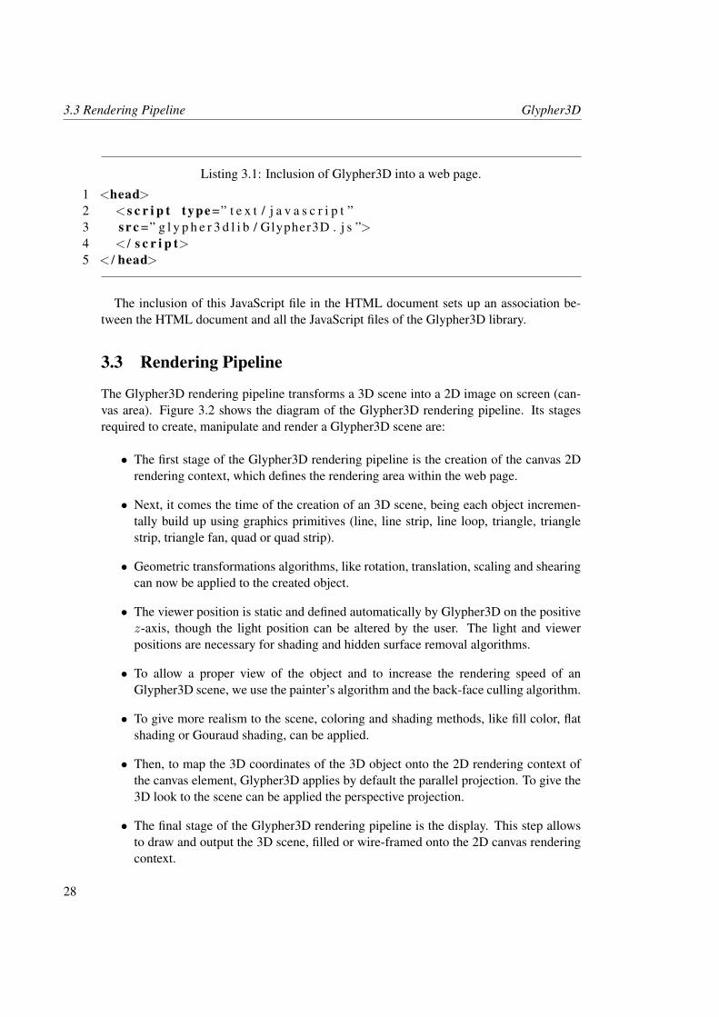
The Glypher3D rendering pipeline transforms a 3D scene into a 2D image on screen (can-vas area). Figure 3.2 shows the diagram of the Glypher3D rendering pipeline. Its stagesrequired to create, manipulate and render a Glypher3D scene are:
• The first stage of the Glypher3D rendering pipeline is the creation of the canvas 2Drendering context, which defines the rendering area within the web page.
• Next, it comes the time of the creation of an 3D scene, being each object incremen-tally build up using graphics primitives (line, line strip, line loop, triangle, trianglestrip, triangle fan, quad or quad strip).
• Geometric transformations algorithms, like rotation, translation, scaling and shearingcan now be applied to the created object.
• The viewer position is static and defined automatically by Glypher3D on the positivez-axis, though the light position can be altered by the user. The light and viewerpositions are necessary for shading and hidden surface removal algorithms.
• To allow a proper view of the object and to increase the rendering speed of anGlypher3D scene, we use the painter’s algorithm and the back-face culling algorithm.
• To give more realism to the scene, coloring and shading methods, like fill color, flatshading or Gouraud shading, can be applied.
• Then, to map the 3D coordinates of the 3D object onto the 2D rendering context ofthe canvas element, Glypher3D applies by default the parallel projection. To give the3D look to the scene can be applied the perspective projection.
• The final stage of the Glypher3D rendering pipeline is the display. This step allowsto draw and output the 3D scene, filled or wire-framed onto the 2D canvas renderingcontext.
28
Glypher3D 3.3 Rendering Pipeline
Canvas 2D Rendering Context
3D Scene Primitives
Geometric Transformations
Projection Transformations
Light and Viewer Positions
Hidden Surface Removal Algorithms
Shading
Rasterization and Display
Points | Line | Line Strip | Line LoopTriangle | Triangle Strip | Triangle Fan
Quad | Quad Strip
Rotation | TranslationScaling | Shearing
Perspective | Parallel
Back-Face Culling | Painter's
Fill Color | Flat ShadingGouraud Shading
Filled | Wire-Framed
Figure 3.2: Glypher3D Rendering Pipeline.
As shown in Figure 3.2, the Glypher3D rendering pipeline is somehow simpler (hasless steps) than the classic rendering pipeline. This happens, because the Glypher3D ren-dering pipeline is intended to provide more usability and to allow the render of 3D scenesin a more intuitive and faster way. Therefore, some steps of the classic rendering pipelinewere discarded due to avoid extra and unnecessary calculations. The steps discarded werethe clipping and coordinate normalization. The clipping process cuts the objects that areoutside the rendering (volume) area. In Glypher3D, the positioning of the objects withinthe rendering area is up to the developer, and if the object is placed or moved outside therendering area, it maintains its geometry and can be placed again within the rendering area.The normalization process of coordinates consists in ensuring that the the 3D scene (re-gardless of its size) will fit into the 2D rendering area. In Glypher3D, the developer must
29
3.4 Creation of the Canvas 2D Rendering Context Glypher3D
create objects within the rendering area. The full and detailed explanation of the Glypher3Drendering pipeline stages will be described in the next sections.
3.4 Creation of the Canvas 2D Rendering Context
As shown in Figure 3.2, the creation of a canvas 2D rendering context is the first stage ofthe rendering pipeline. This is done by adding the HTML canvas tag to the body of the webpage, as shown in Listing 3.2. The canvas tag is used to define a rectangular region of pixels(i.e. a viewport or canvas), where the 3D contents will be output to.
Listing 3.2: Canvas tag added on web page.
1 <body>2 <c an va s id =” a r e a ” width=” 600 ” h e i g h t =” 600 ”>< / c a nv as>3 < / body>
Listing 3.2 shows that the canvas tag has a string identifier (id=”area”), a width and heightparameters. The string identifier is necessary to get access to the canvas tag. It is not specificto this tag, but it is the default HTML parameter that can be applied to almost every HTMLtag. The width and height parameters are optional, and serve to define the size of the canvasarea in pixels. If no width and height are specified, the canvas area is created with thedefault size, which is 300 pixels wide and 150 pixels high. The size of the canvas area canalso be defined using an Cascading Style Sheet (CSS) file. Optional HTML style attributesas, for example, border size and background color can be applied to the canvas tag. Theseattributes do not affect in any way the rendering of Glypher3D objects onto the canvas area.By default, the background color of the canvas area is white [11].
After adding the canvas tag to the web page, this tag become accessible through itsidentifier, i.e. id=”area”. Accessing to the canvas tag and retrieval of the canvas DOM nodeis done as in Listing 3.3.
Listing 3.3: Retrieval of the canvas DOM node using the getElementById method.
1 <s c r i p t type =” t e x t / j a v a s c r i p t ”>2 v a r ca n va s = document . ge tE lemen tById ( ’ a r ea ’ ) ;3 < / s c r i p t>
Now, it is possible to access to the 2D rendering context using the canvas getContextmethod. The access to the rendering context is done using the following Glypher3D method:
• GLY INIT 2D(canvas DOM node).
This method must be used as in Listing 3.4.
30
Glypher3D 3.4 Creation of the Canvas 2D Rendering Context
Listing 3.4: Creation of the canvas 2D rendering context.
1 <s c r i p t type =” t e x t / j a v a s c r i p t ”>2 GLY INIT 2D ( c an v as ) ;3 < / s c r i p t>
This method creates a global CanvasRenderingContext2D object as needed to ren-der scenes on the rendering area. A full example that illustrates the creation of a canvas 2Drendering context, as a starting point to create, manipulate and display 3D contents usingGlypher3D, is shown in Listing 3.5.
Listing 3.5: Creation of the canvas 2D rendering context within a web page.
1 <html>2 <head>3 < t i t l e>I n c l u d e ” ca nv as ” on page< / t i t l e>4 <s c r i p t type =” t e x t / j a v a s c r i p t ”5 s r c =” g l y p h e r 3 d l i b / Glypher3D . j s ”>6 < / s c r i p t>7 <s c r i p t type =” t e x t / j a v a s c r i p t ”>8 v a r ca n va s = document . ge tE lemen tById ( ’ a r ea ’ ) ;9 GLY INIT 2D ( c an v as ) ;
10 < / s c r i p t>11 < / head>12 <body>13 <c an va s id =” a r e a ” width=” 600 ” h e i g h t =” 600 ”>< / c a nv a s>14 < / body>15 < / html>
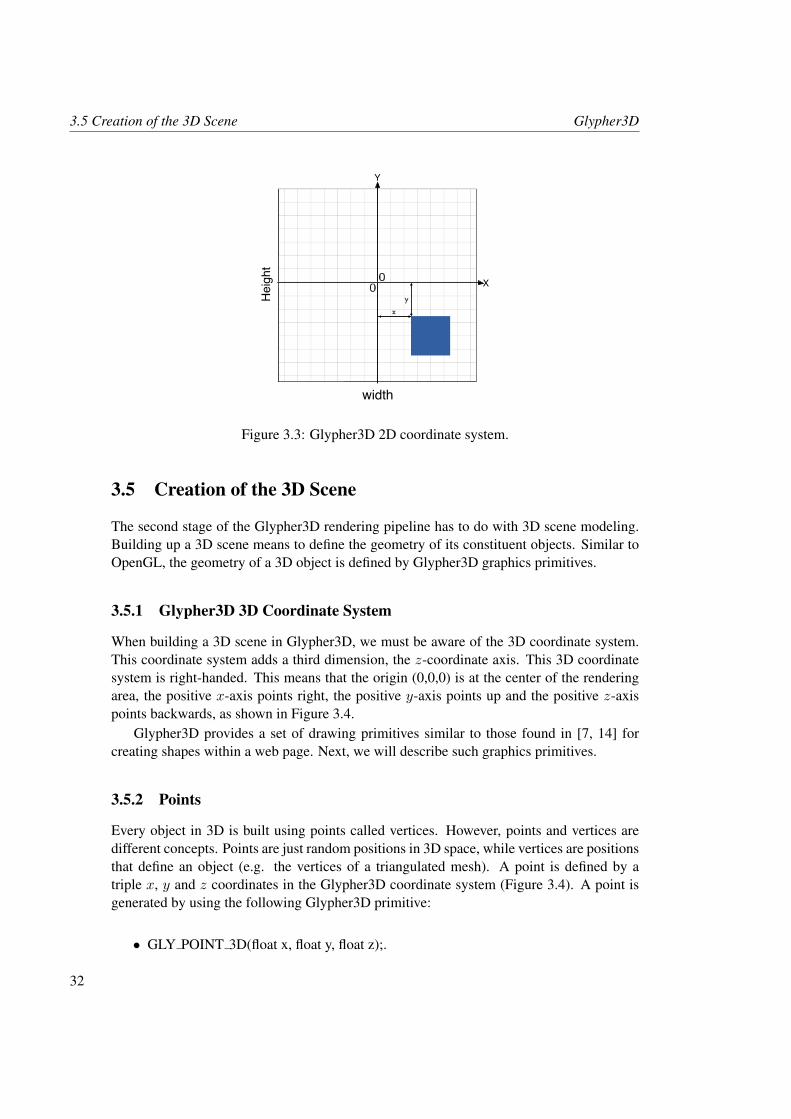
By default, the canvas 2D rendering context represents a discrete coordinate system (i.e.grid of pixels) whose origin (0,0) is at the top left corner, with the positive y-axis pointingdown. In Glypher3D, the origin of this coordinate system is considered to be at the center,with the positive x-axis pointing right and the positive y-axis pointing up, as illustrated inFigure 3.3.
To change the default canvas y-axis orientation (down) to the standard orientation (up),we internally invert the signal of the y-coordinates of all vertices used in the scene. Tochange the origin of the default coordinate system, from the top left corner to the centerof the canvas area, we internally add the values width/2 and height/2 to the x- and y-coordinates of every vertex used in the scene. This process is done before rendering thescene.
31
3.5 Creation of the 3D Scene Glypher3D
Y
width
Height
X
Figure 3.3: Glypher3D 2D coordinate system.
3.5 Creation of the 3D Scene
The second stage of the Glypher3D rendering pipeline has to do with 3D scene modeling.Building up a 3D scene means to define the geometry of its constituent objects. Similar toOpenGL, the geometry of a 3D object is defined by Glypher3D graphics primitives.
3.5.1 Glypher3D 3D Coordinate System
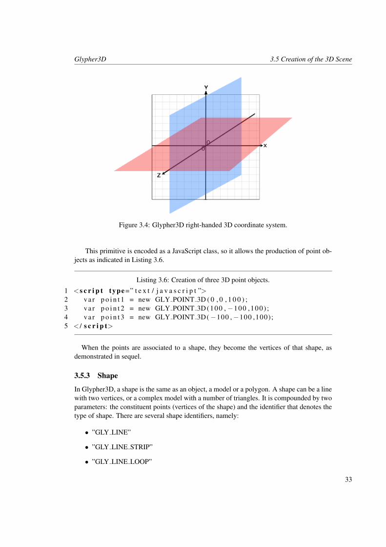
When building a 3D scene in Glypher3D, we must be aware of the 3D coordinate system.This coordinate system adds a third dimension, the z-coordinate axis. This 3D coordinatesystem is right-handed. This means that the origin (0,0,0) is at the center of the renderingarea, the positive x-axis points right, the positive y-axis points up and the positive z-axispoints backwards, as shown in Figure 3.4.
Glypher3D provides a set of drawing primitives similar to those found in [7, 14] forcreating shapes within a web page. Next, we will describe such graphics primitives.
3.5.2 Points
Every object in 3D is built using points called vertices. However, points and vertices aredifferent concepts. Points are just random positions in 3D space, while vertices are positionsthat define an object (e.g. the vertices of a triangulated mesh). A point is defined by atriple x, y and z coordinates in the Glypher3D coordinate system (Figure 3.4). A point isgenerated by using the following Glypher3D primitive:
• GLY POINT 3D(float x, float y, float z);.
32
Glypher3D 3.5 Creation of the 3D Scene
Figure 3.4: Glypher3D right-handed 3D coordinate system.
This primitive is encoded as a JavaScript class, so it allows the production of point ob-jects as indicated in Listing 3.6.
Listing 3.6: Creation of three 3D point objects.
1 <s c r i p t type =” t e x t / j a v a s c r i p t ”>2 v a r p o i n t 1 = new GLY POINT 3D ( 0 , 0 , 1 0 0 ) ;3 v a r p o i n t 2 = new GLY POINT 3D (100 , −100 ,100) ;4 v a r p o i n t 3 = new GLY POINT 3D(−100 ,−100 ,100);5 < / s c r i p t>
When the points are associated to a shape, they become the vertices of that shape, asdemonstrated in sequel.
3.5.3 Shape
In Glypher3D, a shape is the same as an object, a model or a polygon. A shape can be a linewith two vertices, or a complex model with a number of triangles. It is compounded by twoparameters: the constituent points (vertices of the shape) and the identifier that denotes thetype of shape. There are several shape identifiers, namely:
• ”GLY LINE”
• ”GLY LINE STRIP”
• ”GLY LINE LOOP”
33
3.5 Creation of the 3D Scene Glypher3D
• ”GLY TRIANGLE”
• ”GLY TRIANGLE STRIP”
• ”GLY TRIANGLE FAN”
• ”GLY QUAD”
• ”GLY QUAD STRIP”
The vertices of the shape are the first parameter of the Glypher3D shape class, and haveto be inserted as an array of points. The second parameter specifies the type of shape, astring, i.e. the shape identifier. Note that, internally, the vertices in the array are all orderedin a clock-wise order for shading purposes. To create an shape object, it is used the followingGlypher3D shape class:
• GLY SHAPE(array of points, primitive string).
The Glypher3D shape class must be coded as in Listing 3.7.
Listing 3.7: Creation of a triangle shape object, using the points created in Listing 3.6.
1 <s c r i p t type =” t e x t / j a v a s c r i p t ”>2 v a r t r i a n g l e = new GLY SHAPE( new Array ( p o i n t 1 , p o i n t 2 , p o i n t 3 )3 , ”GLY TRIANGLE” ) ;4 < / s c r i p t>
Figure 3.5 illustrates how to use all the Glypher3D primitives. The line strip, line loop,triangle strip, triangle fan, and quad strip primitives are just to avoid the duplication ofshared vertices. But, internally, all line strips and line loops are transformed into lines, alltriangle strips and triangle fans are transformed into triangles and all the quad strips aretransformed into quads, meaning that Glypher3D will draw redundant vertices and edgeswhen using the mentioned primitives. This is done to ease the drawing process and not toslow the rendering performance. Next, we will describe the shape identifiers.
3.5.4 Lines
In 3D graphics, lines are considered as line segments, and there is not the concept of infinitelines as it happens in mathematics. The endpoints of an line are defined by vertices. Justlike in OpenGL, it is possible to create three types of line primitives, whose identifiers arethe following:
• ”GLY LINE”.
• ”GLY LINE STRIP”.
• ”GLY LINE LOOP”.
34
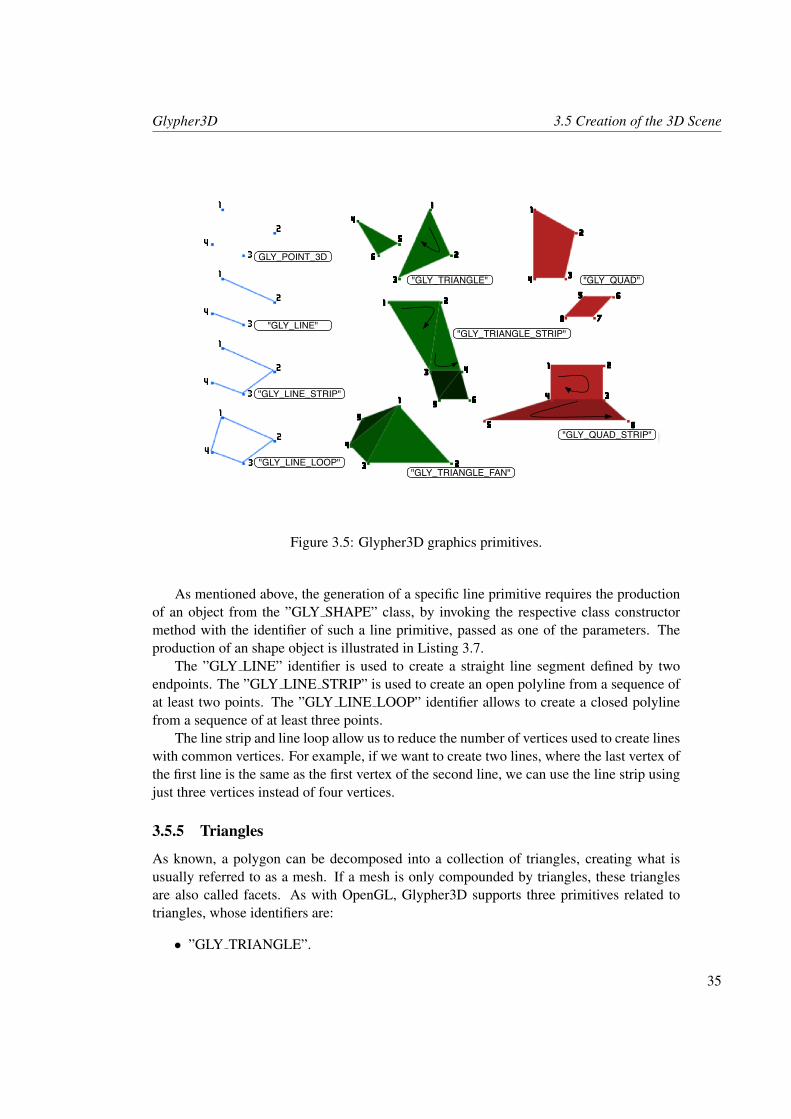
Glypher3D 3.5 Creation of the 3D Scene
1
2
3
4
1 2
3 4
1
23
4
5
1
2
34
5 6
78
1 2
34
5 6
5 6
5
6GLY_POINT_3D
"GLY_LINE"
"GLY_LINE_STRIP"
"GLY_LINE_LOOP"
"GLY_TRIANGLE"
"GLY_TRIANGLE_STRIP"
"GLY_TRIANGLE_FAN"
"GLY_QUAD"
"GLY_QUAD_STRIP"
Figure 3.5: Glypher3D graphics primitives.
As mentioned above, the generation of a specific line primitive requires the productionof an object from the ”GLY SHAPE” class, by invoking the respective class constructormethod with the identifier of such a line primitive, passed as one of the parameters. Theproduction of an shape object is illustrated in Listing 3.7.
The ”GLY LINE” identifier is used to create a straight line segment defined by twoendpoints. The ”GLY LINE STRIP” is used to create an open polyline from a sequence ofat least two points. The ”GLY LINE LOOP” identifier allows to create a closed polylinefrom a sequence of at least three points.
The line strip and line loop allow us to reduce the number of vertices used to create lineswith common vertices. For example, if we want to create two lines, where the last vertex ofthe first line is the same as the first vertex of the second line, we can use the line strip usingjust three vertices instead of four vertices.
3.5.5 Triangles
As known, a polygon can be decomposed into a collection of triangles, creating what isusually referred to as a mesh. If a mesh is only compounded by triangles, these trianglesare also called facets. As with OpenGL, Glypher3D supports three primitives related totriangles, whose identifiers are:
• ”GLY TRIANGLE”.
35
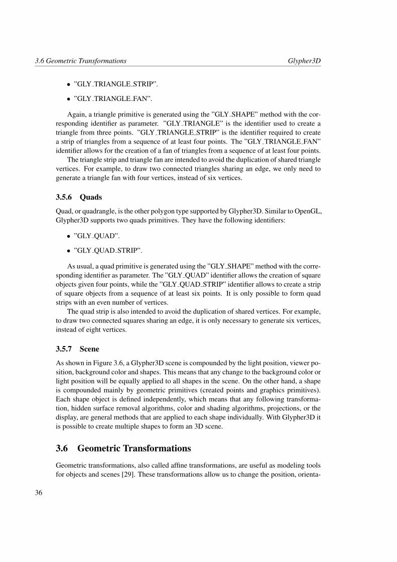
3.6 Geometric Transformations Glypher3D
• ”GLY TRIANGLE STRIP”.
• ”GLY TRIANGLE FAN”.
Again, a triangle primitive is generated using the ”GLY SHAPE” method with the cor-responding identifier as parameter. ”GLY TRIANGLE” is the identifier used to create atriangle from three points. ”GLY TRIANGLE STRIP” is the identifier required to createa strip of triangles from a sequence of at least four points. The ”GLY TRIANGLE FAN”identifier allows for the creation of a fan of triangles from a sequence of at least four points.
The triangle strip and triangle fan are intended to avoid the duplication of shared trianglevertices. For example, to draw two connected triangles sharing an edge, we only need togenerate a triangle fan with four vertices, instead of six vertices.
3.5.6 Quads
Quad, or quadrangle, is the other polygon type supported by Glypher3D. Similar to OpenGL,Glypher3D supports two quads primitives. They have the following identifiers:
• ”GLY QUAD”.
• ”GLY QUAD STRIP”.
As usual, a quad primitive is generated using the ”GLY SHAPE” method with the corre-sponding identifier as parameter. The ”GLY QUAD” identifier allows the creation of squareobjects given four points, while the ”GLY QUAD STRIP” identifier allows to create a stripof square objects from a sequence of at least six points. It is only possible to form quadstrips with an even number of vertices.
The quad strip is also intended to avoid the duplication of shared vertices. For example,to draw two connected squares sharing an edge, it is only necessary to generate six vertices,instead of eight vertices.
3.5.7 Scene
As shown in Figure 3.6, a Glypher3D scene is compounded by the light position, viewer po-sition, background color and shapes. This means that any change to the background color orlight position will be equally applied to all shapes in the scene. On the other hand, a shapeis compounded mainly by geometric primitives (created points and graphics primitives).Each shape object is defined independently, which means that any following transforma-tion, hidden surface removal algorithms, color and shading algorithms, projections, or thedisplay, are general methods that are applied to each shape individually. With Glypher3D itis possible to create multiple shapes to form an 3D scene.
3.6 Geometric Transformations
Geometric transformations, also called affine transformations, are useful as modeling toolsfor objects and scenes [29]. These transformations allow us to change the position, orienta-
36
Glypher3D 3.6 Geometric Transformations
Glypher 3D SceneLight
PositionViewer Position
Background Color
Shapes
Transformations Projections
Hidden Surface Removal
Color and Shading Display
Geometric Primitives
Figure 3.6: Glypher3D scene composition.
tion, size, and shape of the 3D objects through transformation matrices. With them, we canrotate an object, translate an object to a new location, or to change the size of an object.
3.6.1 Rotation
The rotation allows us to change the orientation of an 3D object. The Glypher3D rotationmatrices allow us to rotate an object around the x, y and z axes, given an angle in degrees.
If we want to rotate an object around the x axis, we only change the y and z coordinates.Thus, we do not change the x coordinate, as in the equation system (3.1).
x′ = x
y′ = cos θ.y − sin θ.zz′ = sin θ.y + cos θ.z
(3.1)
This equation system translates into the following matrix form:x′
y′
z′
1
=
1 0 0 00 cos θ − sin θ 00 sin θ cos θ 00 0 0 1
.xyz1
(3.2)
The x, y and z values, correspond to the initial object position. The x′, y′ and z′ values,correspond to the final object position after a rotation around the x axis.
37
3.6 Geometric Transformations Glypher3D
Similar to the rotation around the x axis, to rotate an object around the y axis, we onlychange the x and z coordinates, as expressed in the equation system (3.3).
x′ = cos θ.x+ sin θ.zy′ = y
z′ = − sin θ.x+ cos θ.z(3.3)
This equation system translates into the following matrix form:x′
y′
z′
1
=
cos θ 0 sin θ 0
0 1 0 0− sin θ 0 cos θ 0
0 0 0 1
.xyz1
(3.4)
Similarly to the previous two rotations, to rotate an object around the z axis, we onlychange the x and y coordinates, as expressed in the equation system (3.5).
x′ = cos θ.x− sin θ.yy′ = sin θ.x+ cos θ.yz′ = z
(3.5)
This equation system translates into the following matrix form:x′
y′
z′
1
=
cos θ − sin θ 0 0sin θ cos θ 0 0
0 0 1 00 0 0 1
.xyz1
(3.6)
The Glypher3D rotation methods around the x, y, and z axes are, respectively:
• GLY ROTATION X(float angle).
• GLY ROTATION Y(float angle).
• GLY ROTATION Z(float angle).
Listing 3.8 illustrates the rotation of a triangle, around each coordinate axes, beingθ = 0.8 the rotation angle.
Listing 3.8: All three rotations applied to the triangle shape created in Listing 3.7.
1 <s c r i p t type =” t e x t / j a v a s c r i p t ”>2 t r i a n g l e . GLY ROTATION X ( 0 . 8 ) ;3 t r i a n g l e . GLY ROTATION Y ( 0 . 8 ) ;4 t r i a n g l e . GLY ROTATION Z ( 0 . 8 ) ;5 < / s c r i p t>
38
Glypher3D 3.6 Geometric Transformations
3.6.2 Translation
The translation allow us to change the position of an object, and to place the object in space.Every positional change is a composition of changes along the coordinates axes. Thus, thetranslation can be expressed through the equation system (3.7).
x′ = x+ ∆x
y′ = y + ∆y
z′ = z + ∆z
(3.7)
In equation system (3.7), the ∆x, ∆y, and ∆z stand for the displacement along eachcoordinate axis, x, y, z, respectively.
This equation system translates into the following matrix form:x′
y′
z′
1
=
1 0 0 ∆x
0 1 0 ∆y
0 0 1 ∆z
0 0 0 1
.xyz1
(3.8)
The Glypher3D translation method is:
• GLY TRANSLATION(float x, float y, float z).
In Listing 3.9, we have a translation of a triangle by ∆x = −100, ∆y = 0, and ∆z = 0.
Listing 3.9: Translation applied to the triangle shape created in Listing 3.7.
1 <s c r i p t type =” t e x t / j a v a s c r i p t ”>2 t r i a n g l e . GLY TRANSLATION( −100 ,0 , 0 ) ;3 < / s c r i p t>
3.6.3 Scaling
The scaling transformation allow us to increase or decrease the original size of the objectalong the x, y, and z axes. Let us denote λx, λy, and λz as the scaling factors along thex-, y-, and z-axis, respectively. Dilating an object requires that at least one of the scalingfactors is greater than 1. On the contrary, a contraction is performed using a positive scalingfactor lesser than 1.
The scaling transformation can be expressed through the equation system (3.9).x′ = x.λx
y′ = y.λy
z′ = z.λz
(3.9)
39
3.6 Geometric Transformations Glypher3D
This equation system translates into the following matrix form:x′
y′
z′
1
=
λx 0 0 00 λy 0 00 0 λz 00 0 0 1
.xyz1
(3.10)
The Glypher3D scaling method is:
• GLY SCALING(float x, float y, float z).
In Listing 3.10, the triangle has been applied a non-uniform scaling with factors λx =0.5, λy = 0.8, and λy = 1.
Listing 3.10: Scaling applied to the triangle shape created in Listing 3.7.
1 <s c r i p t type =” t e x t / j a v a s c r i p t ”>2 t r i a n g l e . GLY SCALING ( 0 . 5 , 0 . 8 , 1 ) ;3 < / s c r i p t>
3.6.4 Shearing
In Glypher3D, the shearing transformation is performed along the x, y, and z-axes. Shear-ing distorts the shape and changes the position of the object along the coordinate axes. Theκx, κy, and κz are the shearing factors along the x, y and z-axes.
The shearing transformation can be expressed through the equation system (3.11).x′ = x+ (κx.y) + (κx.z)y′ = y + (κy.x) + (κy.z)z′ = z + (κz.x) + (κz.y)
(3.11)
This equation system translates into the following matrix form:x′
y′
z′
1
=
1 κx κx 0κy 1 κy 0κz κz 1 00 0 0 1
.xyz1
(3.12)
The Glypher3D shearing method is:
• GLY SHEARING(float x, float y, float z).
In Listing 3.11, the triangle is distorted along the x-axis with a shearing factor ofκx = 0.8, κy = 0 and κz = 0.
40
Glypher3D 3.7 Light and Viewer Positions
Listing 3.11: Shearing applied to the triangle shape created in Listing 3.7. Shape sheared inthe x axis.
1 <s c r i p t type =” t e x t / j a v a s c r i p t ”>2 t r i a n g l e . GLY SHEARING ( 0 . 8 , 0 , 0 ) ;3 < / s c r i p t>
3.7 Light and Viewer Positions
In 3D, we must define the positions of viewer and light. This is mandatory for back-face culling, as well as for illumination purposes (flat shading and Gouraud shading). InGlypher3D, the viewer position is always static, defined by default on the positive z-axisand pointing in a negative direction towards the center (0,0,0) of the canvas area. It is es-sential for the back-face culling and Gouraud shading. On the other hand, the position ofthe light in a scene is mandatory for illumination and shading algorithms (flat shading andGouraud shading), as needed to provide realistic scenes. In short, the viewer and light areconstituent objects of a scene. The light and viewer positions influence in the same mannerall the objects within an Glypher3D scene.
The final position of these vectors is always the center of the canvas area (0,0,0), andit is only possible the change the initial position of the light vector. The viewer vector isalways in the z-axis. For example, by changing the light position to the left, while applyinga flat shading algorithm, the faces of the object will be brighter on the left side and darkeron the opposite side.
The light position method is:
• GLY LIGHT POSITION(float x, float y, float z).
To apply this method to an Glypher3D scene, we proceed as in Listing 3.12.
Listing 3.12: Changes on the light vector position applied to an Glypher3D scene.1 <s c r i p t type =” t e x t / j a v a s c r i p t ”>2 GLY LIGHT POSITION ( −100 ,0 ,100) ;3 < / s c r i p t>
An example of the light vector in action can be seen in Figure 3.7.
3.8 Hidden Surface Removal Algorithms
Glypher3D implements two hidden surface removal algorithms: the painter’s algorithm andthe back-face culling algorithm. Although the painter’s algorithm does not remove any faceof the object, we have included it in this category because it deals with the face positions ofthe objects in the scene. It can be considered as a depth sorting algorithm. These algorithms
41
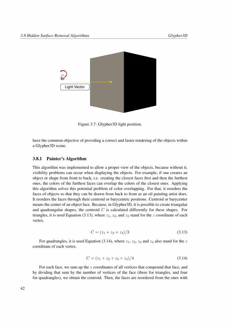
3.8 Hidden Surface Removal Algorithms Glypher3D
Light Vector
Figure 3.7: Glypher3D light position.
have the common objective of providing a correct and faster rendering of the objects withina Glypher3D scene.
3.8.1 Painter’s Algorithm
This algorithm was implemented to allow a proper view of the objects, because without it,visibility problems can occur when displaying the objects. For example, if one creates anobject or shape from front to back, i.e. creating the closest faces first and then the furthestones, the colors of the furthest faces can overlap the colors of the closest ones. Applyingthis algorithm solves this potential problem of color overlapping. For that, it reorders thefaces of objects so that they can be drawn from back to front as an oil painting artist does.It reorders the faces through their centroid or barycentric positions. Centroid or barycentermeans the center of an object face. Because, in Glypher3D, it is possible to create triangularand quadrangular shapes, the centroid C is calculated differently for these shapes. Fortriangles, it is used Equation (3.13), where z1, z2, and z3 stand for the z coordinate of eachvertex.
C = (z1 + z2 + z3)/3 (3.13)
For quadrangles, it is used Equation (3.14), where z1, z2, z3 and z4 also stand for the zcoordinate of each vertex.
C = (z1 + z2 + z3 + z4)/4 (3.14)
For each face, we sum up the z coordinates of all vertices that compound that face, andby dividing that sum by the number of vertices of the face (three for triangles, and fourfor quadrangles), we obtain the centroid. Then, the faces are reordered from the ones with
42
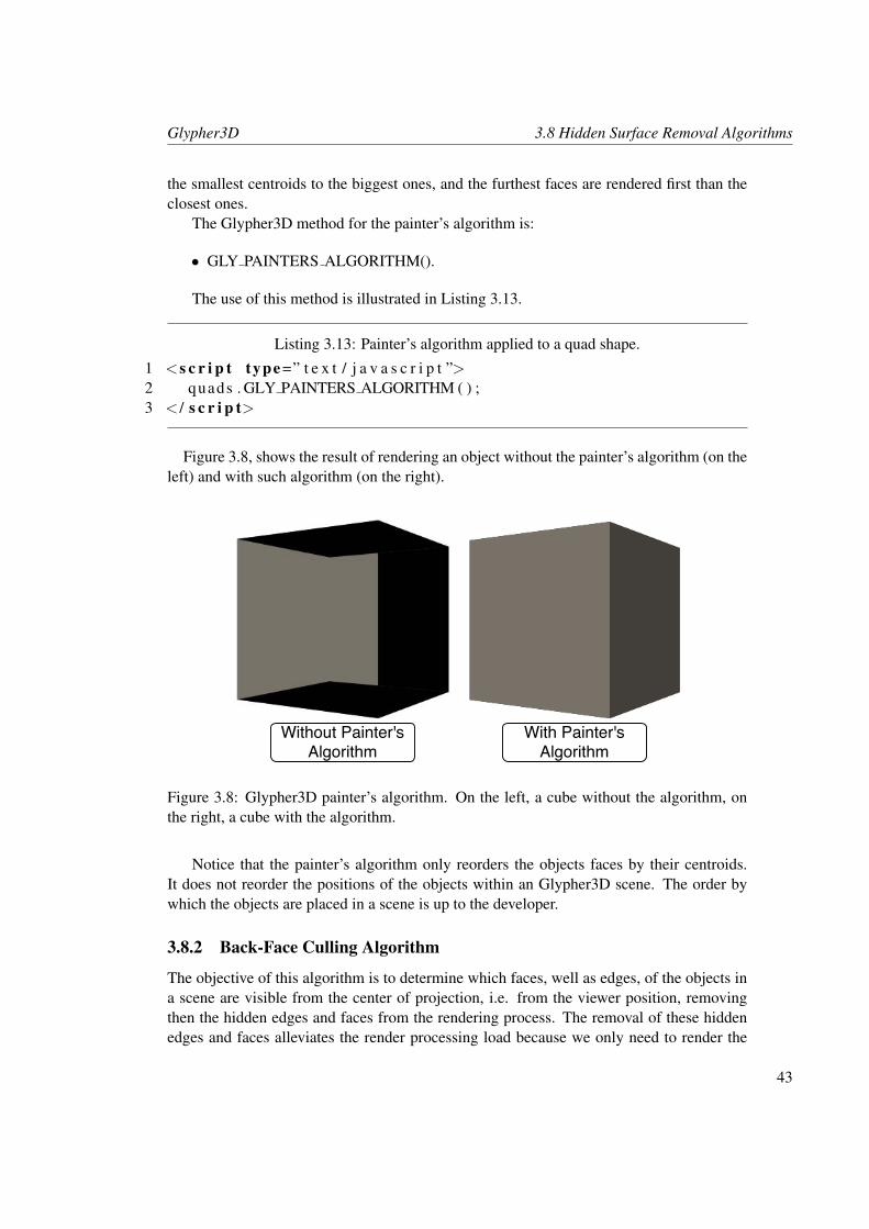
Glypher3D 3.8 Hidden Surface Removal Algorithms
the smallest centroids to the biggest ones, and the furthest faces are rendered first than theclosest ones.
The Glypher3D method for the painter’s algorithm is:
• GLY PAINTERS ALGORITHM().
The use of this method is illustrated in Listing 3.13.
Listing 3.13: Painter’s algorithm applied to a quad shape.
1 <s c r i p t type =” t e x t / j a v a s c r i p t ”>2 quads . GLY PAINTERS ALGORITHM ( ) ;3 < / s c r i p t>
Figure 3.8, shows the result of rendering an object without the painter’s algorithm (on theleft) and with such algorithm (on the right).
Without Painter's Algorithm
With Painter's Algorithm
Figure 3.8: Glypher3D painter’s algorithm. On the left, a cube without the algorithm, onthe right, a cube with the algorithm.
Notice that the painter’s algorithm only reorders the objects faces by their centroids.It does not reorder the positions of the objects within an Glypher3D scene. The order bywhich the objects are placed in a scene is up to the developer.
3.8.2 Back-Face Culling Algorithm
The objective of this algorithm is to determine which faces, well as edges, of the objects ina scene are visible from the center of projection, i.e. from the viewer position, removingthen the hidden edges and faces from the rendering process. The removal of these hiddenedges and faces alleviates the render processing load because we only need to render the
43
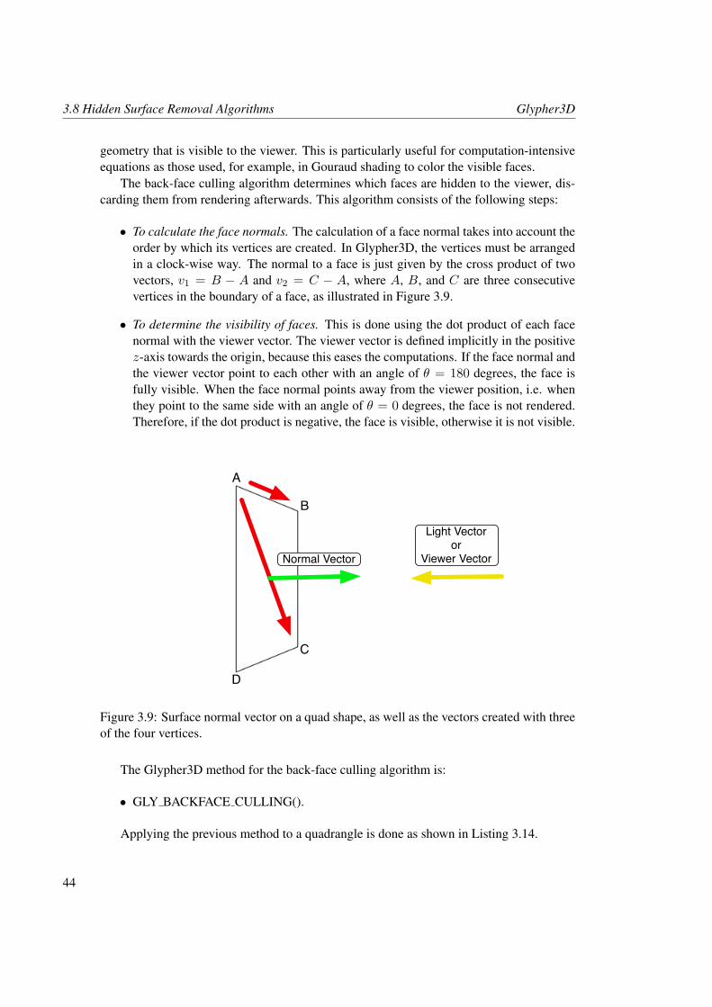
3.8 Hidden Surface Removal Algorithms Glypher3D
geometry that is visible to the viewer. This is particularly useful for computation-intensiveequations as those used, for example, in Gouraud shading to color the visible faces.
The back-face culling algorithm determines which faces are hidden to the viewer, dis-carding them from rendering afterwards. This algorithm consists of the following steps:
• To calculate the face normals. The calculation of a face normal takes into account theorder by which its vertices are created. In Glypher3D, the vertices must be arrangedin a clock-wise way. The normal to a face is just given by the cross product of twovectors, v1 = B − A and v2 = C − A, where A, B, and C are three consecutivevertices in the boundary of a face, as illustrated in Figure 3.9.
• To determine the visibility of faces. This is done using the dot product of each facenormal with the viewer vector. The viewer vector is defined implicitly in the positivez-axis towards the origin, because this eases the computations. If the face normal andthe viewer vector point to each other with an angle of θ = 180 degrees, the face isfully visible. When the face normal points away from the viewer position, i.e. whenthey point to the same side with an angle of θ = 0 degrees, the face is not rendered.Therefore, if the dot product is negative, the face is visible, otherwise it is not visible.
A
B
C
D
Light Vectoror
Viewer VectorNormal Vector
Figure 3.9: Surface normal vector on a quad shape, as well as the vectors created with threeof the four vertices.
The Glypher3D method for the back-face culling algorithm is:
• GLY BACKFACE CULLING().
Applying the previous method to a quadrangle is done as shown in Listing 3.14.
44
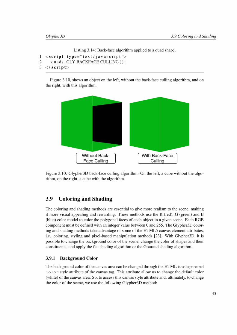
Glypher3D 3.9 Coloring and Shading
Listing 3.14: Back-face algorithm applied to a quad shape.1 <s c r i p t type =” t e x t / j a v a s c r i p t ”>2 quads . GLY BACKFACE CULLING ( ) ;3 < / s c r i p t>
Figure 3.10, shows an object on the left, without the back-face culling algorithm, and onthe right, with this algorithm.
Without Back-Face Culling
With Back-Face Culling
Figure 3.10: Glypher3D back-face culling algorithm. On the left, a cube without the algo-rithm, on the right, a cube with the algorithm.
3.9 Coloring and Shading
The coloring and shading methods are essential to give more realism to the scene, makingit more visual appealing and rewarding. These methods use the R (red), G (green) and B(blue) color model to color the polygonal faces of each object in a given scene. Each RGBcomponent must be defined with an integer value between 0 and 255. The Glypher3D color-ing and shading methods take advantage of some of the HTML5 canvas element attributes,i.e. coloring, styling and pixel-based manipulation methods [23]. With Glypher3D, it ispossible to change the background color of the scene, change the color of shapes and theirconstituents, and apply the flat shading algorithm or the Gouraud shading algorithm.
3.9.1 Background Color
The background color of the canvas area can be changed through the HTML backgroundColor style attribute of the canvas tag. This attribute allow us to change the default color(white) of the canvas area. So, to access this canvas style attribute and, ultimately, to changethe color of the scene, we use the following Glypher3D method:
45
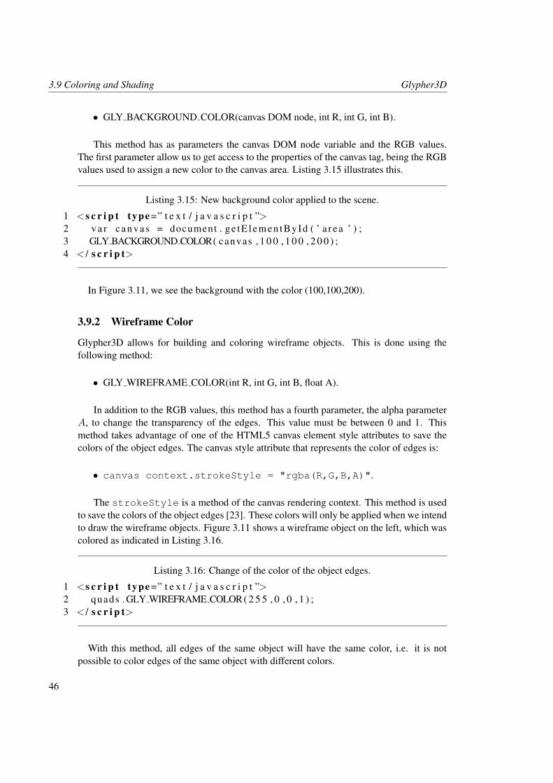
3.9 Coloring and Shading Glypher3D
• GLY BACKGROUND COLOR(canvas DOM node, int R, int G, int B).
This method has as parameters the canvas DOM node variable and the RGB values.The first parameter allow us to get access to the properties of the canvas tag, being the RGBvalues used to assign a new color to the canvas area. Listing 3.15 illustrates this.
Listing 3.15: New background color applied to the scene.
1 <s c r i p t type =” t e x t / j a v a s c r i p t ”>2 v a r ca n va s = document . ge tE lemen tById ( ’ a r ea ’ ) ;3 GLY BACKGROUND COLOR( canvas , 1 0 0 , 1 0 0 , 2 0 0 ) ;4 < / s c r i p t>
In Figure 3.11, we see the background with the color (100,100,200).
3.9.2 Wireframe Color
Glypher3D allows for building and coloring wireframe objects. This is done using thefollowing method:
• GLY WIREFRAME COLOR(int R, int G, int B, float A).
In addition to the RGB values, this method has a fourth parameter, the alpha parameterA, to change the transparency of the edges. This value must be between 0 and 1. Thismethod takes advantage of one of the HTML5 canvas element style attributes to save thecolors of the object edges. The canvas style attribute that represents the color of edges is:
• canvas context.strokeStyle = "rgba(R,G,B,A)".
The strokeStyle is a method of the canvas rendering context. This method is usedto save the colors of the object edges [23]. These colors will only be applied when we intendto draw the wireframe objects. Figure 3.11 shows a wireframe object on the left, which wascolored as indicated in Listing 3.16.
Listing 3.16: Change of the color of the object edges.
1 <s c r i p t type =” t e x t / j a v a s c r i p t ”>2 quads . GLY WIREFRAME COLOR( 2 5 5 , 0 , 0 , 1 ) ;3 < / s c r i p t>
With this method, all edges of the same object will have the same color, i.e. it is notpossible to color edges of the same object with different colors.
46
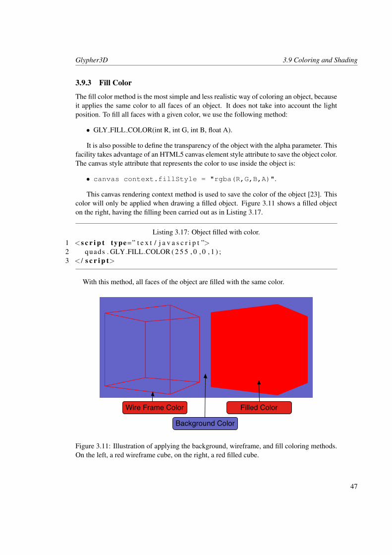
Glypher3D 3.9 Coloring and Shading
3.9.3 Fill Color
The fill color method is the most simple and less realistic way of coloring an object, becauseit applies the same color to all faces of an object. It does not take into account the lightposition. To fill all faces with a given color, we use the following method:
• GLY FILL COLOR(int R, int G, int B, float A).
It is also possible to define the transparency of the object with the alpha parameter. Thisfacility takes advantage of an HTML5 canvas element style attribute to save the object color.The canvas style attribute that represents the color to use inside the object is:
• canvas context.fillStyle = "rgba(R,G,B,A)".
This canvas rendering context method is used to save the color of the object [23]. Thiscolor will only be applied when drawing a filled object. Figure 3.11 shows a filled objecton the right, having the filling been carried out as in Listing 3.17.
Listing 3.17: Object filled with color.1 <s c r i p t type =” t e x t / j a v a s c r i p t ”>2 quads . GLY FILL COLOR ( 2 5 5 , 0 , 0 , 1 ) ;3 < / s c r i p t>
With this method, all faces of the object are filled with the same color.
Wire Frame Color Filled Color
Background Color
Figure 3.11: Illustration of applying the background, wireframe, and fill coloring methods.On the left, a red wireframe cube, on the right, a red filled cube.
47
3.9 Coloring and Shading Glypher3D
3.9.4 Flat Shading
Until know, the only way to assign a color to an object was by filling all object faces withthe same color. However, this filling process is not realistic in 3D. A more realistic shadingtechnique is given by the flat shading algorithm. For that, it shades each face of the objecttaking into account the light position-defined vector and each face normal. If these vectorsform an angle of θ = 180 degrees (point to each other), the surface has maximum colorintensity and becomes brighter, but when this angle decreases to zero, the color intensityalso decreases and becomes darker.
The flat shading algorithm has thus the following steps:
• To calculate the face normals. This step is identical to the first step of the back-faceculling.
• To compute the color intensity of each face. This is done by computing the dot productof two vectors: face normal and light position-defined vector. This product providesus with the color intensity.
• To compute the color of each face. Calculated the color intensity I , between 0 and 1,of each face in the previous step, it remains to compute its color by using Equations(3.15):
R′ = R.I (3.15a)
G′ = G.I (3.15b)
B′ = B.I (3.15c)
Where R, G, and B values are the color parameters introduced by the user, and R′, G′,andB′ values compound to the final color of each face. Now, we have different RGB colorsfor each face of the object. Notice that the color is constant for the same face, but differentfaces have different intensities, i.e. it is brighter or darker due to the intensities values. TheGlypher3D flat shading method is specified as follows:
• GLY FLAT SHADING(int R, int G, int B, float A).
Like the wireframe and fill color methods, it is possible the change the transparency ofthe object. Again, the flat shading method uses the canvas context fillStyle methodto save the color of each face of the object. This color is only applied to the faces of theobject when the object is drawn. As an example, let us apply the flat shading algorithm to atriangle as in Listing 3.18.
Listing 3.18: Flat shading an object.1 <s c r i p t type =” t e x t / j a v a s c r i p t ”>2 t r i a n g l e . GLY FLAT SHADING ( 2 5 5 , 0 , 0 , 1 ) ;3 < / s c r i p t>
48
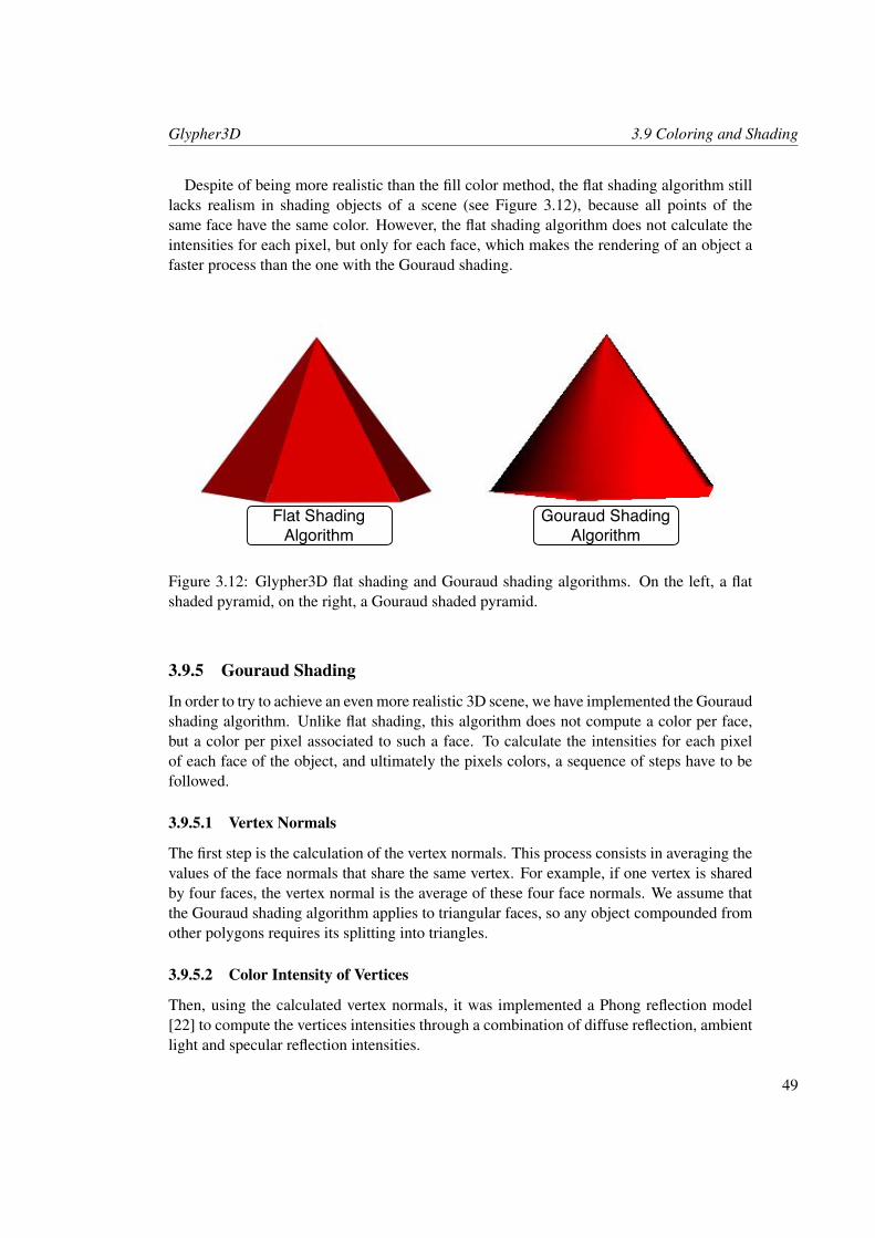
Glypher3D 3.9 Coloring and Shading
Despite of being more realistic than the fill color method, the flat shading algorithm stilllacks realism in shading objects of a scene (see Figure 3.12), because all points of thesame face have the same color. However, the flat shading algorithm does not calculate theintensities for each pixel, but only for each face, which makes the rendering of an object afaster process than the one with the Gouraud shading.
Gouraud Shading Algorithm
Flat Shading Algorithm
Figure 3.12: Glypher3D flat shading and Gouraud shading algorithms. On the left, a flatshaded pyramid, on the right, a Gouraud shaded pyramid.
3.9.5 Gouraud Shading
In order to try to achieve an even more realistic 3D scene, we have implemented the Gouraudshading algorithm. Unlike flat shading, this algorithm does not compute a color per face,but a color per pixel associated to such a face. To calculate the intensities for each pixelof each face of the object, and ultimately the pixels colors, a sequence of steps have to befollowed.
3.9.5.1 Vertex Normals
The first step is the calculation of the vertex normals. This process consists in averaging thevalues of the face normals that share the same vertex. For example, if one vertex is sharedby four faces, the vertex normal is the average of these four face normals. We assume thatthe Gouraud shading algorithm applies to triangular faces, so any object compounded fromother polygons requires its splitting into triangles.
3.9.5.2 Color Intensity of Vertices
Then, using the calculated vertex normals, it was implemented a Phong reflection model[22] to compute the vertices intensities through a combination of diffuse reflection, ambientlight and specular reflection intensities.
49
3.9 Coloring and Shading Glypher3D
Objects do not emit light, but they reflect any light that illuminates them. The diffuselight or diffuse reflection depends on the light and object positions. To calculate the diffusereflection intensity Id, first, it is calculated the dot product between each vertex normals VN
and the light vector L. Then, this value is multiplied by aKd constant between 0 and 1, as itis done in Equation (3.16). This constant is an parameter of the Gouraud shading algorithmand represents an approximated value of the diffuse reflectivity.
Id = Kd(L.VN ) (3.16)
The ambient light does not have direction or position and is a result of multiple reflec-tions. It illuminates a face from all directions. The intensity of the ambient light Iambient,is calculated using Equation (3.17).
Iambient = Ia.Ka (3.17)
In Equation (3.17), Ia is the intensity of the ambient light and Ka is the ambient refec-tion coefficient. Ia and Ka are two constants with values between 0 and 1, also passed asparameters to the Gouraud shading algorithm.
The specular light or specular reflection is intended to create glossy regions on thesurface of the object. It takes into account the light position, the viewer position and theobject position. The calculation of the specular intensity involves two steps: first, it iscalculated the S term, which is an approximation of the reflection vector, using Equations(3.18):
Sx = (Lx + Vx)/2 (3.18a)
Sy = (Ly + Vy)/2 (3.18b)
Sz = (Lz + Vz)/2 (3.18c)
Where L = (Lx, Ly, Lz) and V = (Vx, Vy, Vz) are the light vector and the viewervector respectively.
Because the calculation of the reflection vector requires more computational work, in-stead of this vector, it is calculated the S term, which basically is a unit normal with adirection between the light vector L and the viewer vector V .
Finally, to obtain the specular intensity Is, it is first calculated the dot product betweenthe vertices normals vector VN and the S term. Then, this value is multiplied by a Ks con-stant between 0 and 1, as is done in Equation (3.19). The Ks constant is also an parameterof the Gouraud shading algorithm and denotes the specular reflection coefficient.
Is = Ks(S.VN ) (3.19)
By combining the diffuse reflection, the ambient light and the specular reflection, weobtain Equation (3.20) for the calculation of the intensities Ivertex for each vertex.
Ivertex = Iambient + Li.(Id + Ins ) (3.20)
50
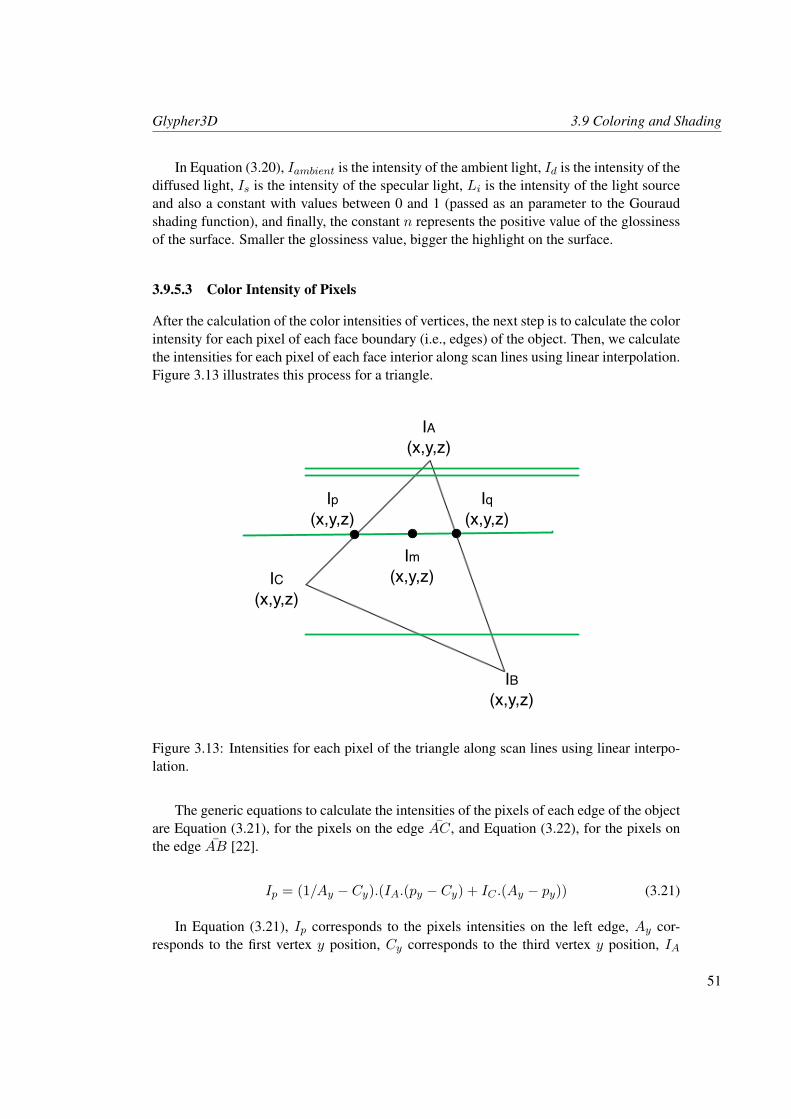
Glypher3D 3.9 Coloring and Shading
In Equation (3.20), Iambient is the intensity of the ambient light, Id is the intensity of thediffused light, Is is the intensity of the specular light, Li is the intensity of the light sourceand also a constant with values between 0 and 1 (passed as an parameter to the Gouraudshading function), and finally, the constant n represents the positive value of the glossinessof the surface. Smaller the glossiness value, bigger the highlight on the surface.
3.9.5.3 Color Intensity of Pixels
After the calculation of the color intensities of vertices, the next step is to calculate the colorintensity for each pixel of each face boundary (i.e., edges) of the object. Then, we calculatethe intensities for each pixel of each face interior along scan lines using linear interpolation.Figure 3.13 illustrates this process for a triangle.
C
IA(x,y,z)
IB(x,y,z)
IC(x,y,z)
Ip(x,y,z)
Iq(x,y,z)
Im(x,y,z)
Figure 3.13: Intensities for each pixel of the triangle along scan lines using linear interpo-lation.
The generic equations to calculate the intensities of the pixels of each edge of the objectare Equation (3.21), for the pixels on the edge AC, and Equation (3.22), for the pixels onthe edge AB [22].
Ip = (1/Ay − Cy).(IA.(py − Cy) + IC .(Ay − py)) (3.21)
In Equation (3.21), Ip corresponds to the pixels intensities on the left edge, Ay cor-responds to the first vertex y position, Cy corresponds to the third vertex y position, IA
51
3.9 Coloring and Shading Glypher3D
corresponds to the intensity on the first vertex, py corresponds to the y positions of the leftpixels, and IC corresponds to the intensity on the third vertex.
Iq = (1/Ay −By).(IA.(qy −By) + IB.(Ay − qy)) (3.22)
In Equation (3.22), Iq corresponds to the pixels intensities on the right edge, Ay cor-responds to the first vertex y position, By corresponds to the second vertex y position, IAcorresponds to the intensity on the first vertex, qy corresponds to the y positions of the rightpixels, and IB corresponds to the intensity on the second vertex.
To obtain just the positions of the pixels from the edges was used the Bresenham linealgorithm. To calculate the intensities for each pixel of each face interior along scan linesusing linear interpolation, we use Equation (3.23).
Im = (1/qx − px).(Ip.(qx −mx) + Iq.(mx − px)) (3.23)
In Equation (3.23), Im corresponds to the pixels intensities in the interior of a face, qxcorresponds to the x positions of the right pixels, px corresponds to the x positions of theleft pixels, Ip corresponds to the pixel intensities on the left edge, mx corresponds to the xpositions of the pixels in the interior of a face, and Iq corresponds to the pixel intensities onthe right edge.
To obtain the positions of the pixels in the interior of a face (mx), were covered all thepixels between the pixels on the left edge (px) and the pixels on the right edge (qx).
Now that all the pixels intensities are calculated, the last step on the Gouraud shadingalgorithm is to set the pixels colors. To do that, we use Equations (3.24):
R′ = R.Ipixel (3.24a)
G′ = G.Ipixel (3.24b)
B′ = B.Ipixel (3.24c)
The R, G, and B values are the color parameters introduced by the user, and the R′, G′,and B′ values correspond to the colors intensities of pixels.
Then, the Glypher3D Gouraud shading algorithm uses the following HTML5 canvaselement, pixel-based manipulation methods, to save the pixels colors (only applied to pixelswhen drawing):
• imagedata = canvas context.createImageData(int width, intheight). This method returns an imagedata object with the given dimensions. Theimagedata object can access to the pixels methods to change their size or color. Thewidth and height attributes correspond to the initial pixel size [23]. This method issupported by the Firefox, Safari and Chrome browsers.
• imagedata = canvas context.getImageData(int x, int y, intwidth, int height). This method also returns an imagedata object, however,this object can access to the pixel data from the given rectangle position of the canvas[23]. This method is only supported by the Opera browser.
52
Glypher3D 3.10 Projection Transformations
Both methods provides an imagedata object to manipulate the pixel data inside thecanvas area. However, because not all canvas-compatible browsers support the create-ImageData method, was also implemented the getImageData method. Through theimagedata object is possible to access to each one of the object pixels positions and settheir new RGB colors.
The Glypher3D Gouraud shading method is the following:
• GLY GOURAUD SHADING(float Ia, float Ka, float Kd, float Li, float Ks, int n,int R, int G, int B, int A).
Similar to the previous shading methods, Gouraud shading allows for changing thetransparency of the object. The difference is that now the alpha value is between 0 and255, where the maximum value (255) corresponds to an object without transparency (thesame as 1 on the previous shading methods).
As an example, let us apply the Gouraud shading to a triangle fan, as illustrated in List-ing 3.19 and Figure 3.12.
Listing 3.19: Gouraud shading an object.
1 <s c r i p t type =” t e x t / j a v a s c r i p t ”>2 t r i a n g l e . GLY GOURAUD SHADING( 0 . 2 , 0 . 2 , 1 , 1 , 1 , 0 , 2 5 5 , 0 , 0 , 2 5 5 ) ;3 < / s c r i p t>
In Glypher3D, the Gouraud shading algorithm is the only method that directly handlespixels of the HTML5 canvas element. Because of all the mathematical calculations areperformed in JavaScript, on the client-side, Gouraud shading is slower on browser thanOpenGL on desktop applications that use the capabilities of graphics cards. However, asexpected, the Gouraud technique provides a better and smoother look of the object, as acolor gradient exists on the surface.
3.10 Projection Transformations
A scene and the objects therein are defined in the 3D space. But, in order to display thisscene and its objects onto a 2D rectangular canvas area of the browser, the scene mustbe projected onto a plane in 3D, which is then mapped onto the 2D context of canvas.Therefore, before displaying a scene, we must apply projection transformations to map3D coordinates onto 2D coordinates. There are two main projection techniques: parallelprojection and perspective projection [16, 29].
3.10.1 Parallel Projection
The parallel projection (front orthographic projection), is a less realistic projection, becauseit ignores the z coordinate or depth coordinate, i.e. all the points are projected along parallellines (i.e. the visual rays) because we assume that the viewer is located at infinity. Therefore,
53
3.10 Projection Transformations Glypher3D
there is no foreshortening, i.e. if we had two objects within the scene, one closer and anotherfurther away, they would be rendered with the same size [16, 29]. Glypher3D uses by defaultthe parallel projection, because the rendering process only involves the x and y coordinates.The z coordinate is simply discarded.
3.10.2 Perspective Projection
The perspective projection provides a more realistic visualization (similar to the humanvisual system) of the object and does not ignore the z coordinate, as it happens in parallelprojection. This means that the more distant an object is from the center of projection(origin), smaller it appears, i.e. there is foreshortening. Unlike the parallel projection, inwhich the parallel lines only meet at infinity, in perspective projection, parallel lines meetat the viewer position who is located to a finite distance in the positive z-axis [16, 29]. Inthese circumstances, the perspective projection is given by the equation system (3.25).
x′ = x/z
y′ = y/z
z′ = z
(3.25)
The higher the value of z, smaller the values of x′ and y′, and the final point becomescloser to the viewer. Equation system (3.25) present a problem because the z value cannotbe zero (division by zero). To solve this problem, we introduced two new variables: thewidth and height of the canvas area, changing the equation system (3.25), to the equationsystem (3.26).
x′ = x/(width− z)y′ = y/(height− z)z′ = z
(3.26)
The width and height variables represent the dimensions of the canvas area (in pixels),and are used to maintain the object within it. However, all points still converge to the viewer,and the object continues very small. Therefore, to put the object on a visible scale and withperspective, we multiply the x and y values, respectively, by the width and height values,as shown in equation system (3.27).
x′ = (width.x)/(width− z)y′ = (height.y)/(height− z)z′ = z
(3.27)
This method of perspective projection bypasses the normalization process of coordi-nates as a way to speed up the rendering process. The perspective projection method is thefollowing:
• GLY PERSPECTIVE PROJECTION().
54
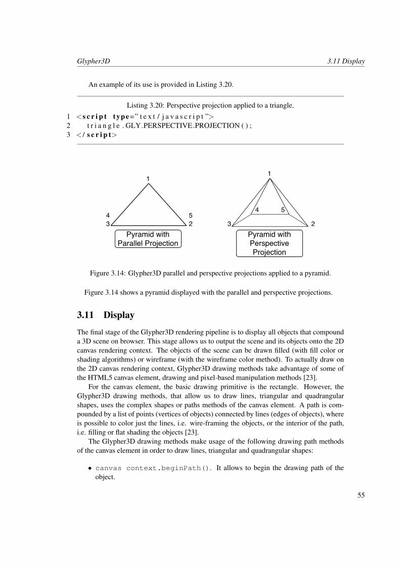
Glypher3D 3.11 Display
An example of its use is provided in Listing 3.20.
Listing 3.20: Perspective projection applied to a triangle.
1 <s c r i p t type =” t e x t / j a v a s c r i p t ”>2 t r i a n g l e . GLY PERSPECTIVE PROJECTION ( ) ;3 < / s c r i p t>
Pyramid with Parallel Projection
1
Pyramid with Perspective Projection
234 5
1
23
4 5
Figure 3.14: Glypher3D parallel and perspective projections applied to a pyramid.
Figure 3.14 shows a pyramid displayed with the parallel and perspective projections.
3.11 Display
The final stage of the Glypher3D rendering pipeline is to display all objects that compounda 3D scene on browser. This stage allows us to output the scene and its objects onto the 2Dcanvas rendering context. The objects of the scene can be drawn filled (with fill color orshading algorithms) or wireframe (with the wireframe color method). To actually draw onthe 2D canvas rendering context, Glypher3D drawing methods take advantage of some ofthe HTML5 canvas element, drawing and pixel-based manipulation methods [23].
For the canvas element, the basic drawing primitive is the rectangle. However, theGlypher3D drawing methods, that allow us to draw lines, triangular and quadrangularshapes, uses the complex shapes or paths methods of the canvas element. A path is com-pounded by a list of points (vertices of objects) connected by lines (edges of objects), whereis possible to color just the lines, i.e. wire-framing the objects, or the interior of the path,i.e. filling or flat shading the objects [23].
The Glypher3D drawing methods make usage of the following drawing path methodsof the canvas element in order to draw lines, triangular and quadrangular shapes:
• canvas context.beginPath(). It allows to begin the drawing path of theobject.
55
3.11 Display Glypher3D
• canvas context.moveTo(x,y). It specifies the starting point of the path, i.e.it starts drawing from this point.
• canvas context.lineTo(x,y). It draws a line from the previous point to thecurrent point. It draws the edges of 3D objects.
• canvas context.closePath(). It closes the path of the object by drawing aline from the current point to the starting point. It forms a closed path.
• canvas context.stroke(). It colors the lines or edges of the object with thestrokeStyle attribute defined with the Glypher3D wireframe color method.
• canvas context.fill(). It fills the object with the fillStyle attributedefined with the Glypher3D fill color or flat shading methods.
These drawing path methods are not used in Gouraud shading. Instead, we use thefollowing pixel-based manipulation drawing method:
• canvas context.putImageData(image data object, int x, inty). This method uses the imagedata object (that contains all information of thepixels, including their size and colors) to draw the pixels at specific positions [23].
Also, through this pixel-based manipulation method, we can draw just the vertices ofthe object through the following Glypher3D method:
• GLY DRAW VERTEXS(int size, int R, int G, int B).
The previous method is used as in Listing 3.21.
Listing 3.21: Drawing the vertices of an object.1 <s c r i p t type =” t e x t / j a v a s c r i p t ”>2 quads . GLY DRAW VERTEXS( 5 , 0 , 2 5 0 , 0 ) ;3 < / s c r i p t>
As mentioned before, Glypher3D allows for drawing filled or wireframe objects. To drawa specific object, we use the following method:
• GLY DRAW(string).
If this method is used without parameters, the object will be drawn with color or withshading. However, if we pass the identifier ”GLY WIREFRAMED” as argument, the objectwill be drawn as a wireframe object.
Therefore, the drawing of an specific object with color or shading is done as in List-ing 3.22. But drawing a wireframe object is done as in Listing 3.23. Figure 3.15 shows ascene with two objects. The first is a wireframe object, while the second is a filled object.The vertices of both objects appear drawn with square marks.
56
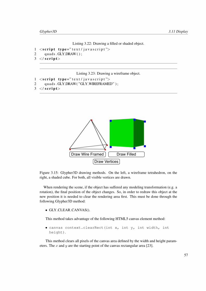
Glypher3D 3.11 Display
Listing 3.22: Drawing a filled or shaded object.
1 <s c r i p t type =” t e x t / j a v a s c r i p t ”>2 quads .GLY DRAW ( ) ;3 < / s c r i p t>
Listing 3.23: Drawing a wireframe object.
1 <s c r i p t type =” t e x t / j a v a s c r i p t ”>2 quads .GLY DRAW( ”GLY WIREFRAMED” ) ;3 < / s c r i p t>
Draw Wire Framed
Draw Vertices
Draw Filled
Figure 3.15: Glypher3D drawing methods. On the left, a wireframe tetrahedron, on theright, a shaded cube. For both, all visible vertices are drawn.
When rendering the scene, if the object has suffered any modeling transformation (e.g. arotation), the final position of the object changes. So, in order to redraw this object at thenew position it is needed to clear the rendering area first. This must be done through thefollowing Glypher3D method:
• GLY CLEAR CANVAS().
This method takes advantage of the following HTML5 canvas element method:
• canvas context.clearRect(int x, int y, int width, intheight).
This method clears all pixels of the canvas area defined by the width and height param-eters. The x and y are the starting point of the canvas rectangular area [23].
57
3.12 Summary Glypher3D
3.12 Summary
To conclude this chapter, it can be said that it is possible to create a 3D graphics pipelineusing only graphics algorithms encoded in JavaScript, together with the HTML5 canvaselement. This Glypher3D rendering pipeline, although simpler than a classic renderingpipeline, provides the essential facilities to create 3D scenes directly on browser. It allows usto create a viewport, 3D scenes with graphics primitives (i.e. with points, lines, line strips,line loops, triangles, triangle strips, triangle fans, quad and quad strips), apply geometrictransformations (i.e. rotation, translation, scaling and shearing), define the light position,apply hidden surface removal algorithms (i.e. back-face culling and painter’s algorithm),apply shading (i.e. flat shading and Gouraud shading), projections transformations (i.e.perspective projection) and finally to display the 3D scene on the 2D viewport.
58
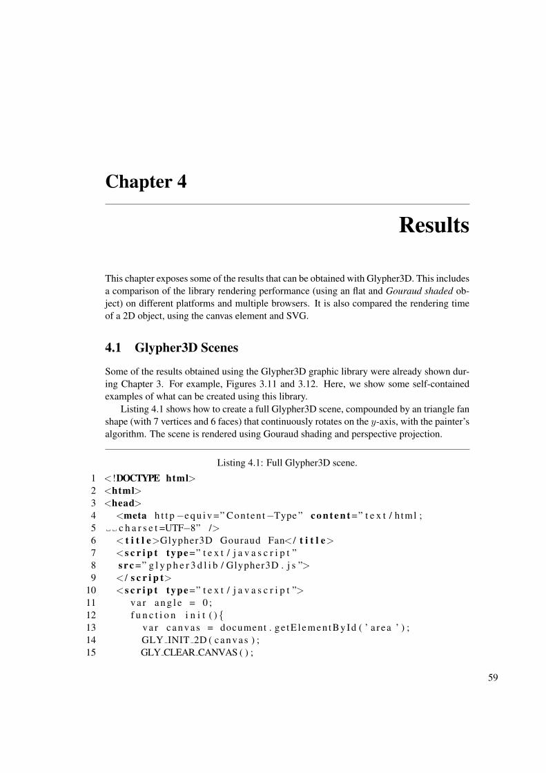
Chapter 4
Results
This chapter exposes some of the results that can be obtained with Glypher3D. This includesa comparison of the library rendering performance (using an flat and Gouraud shaded ob-ject) on different platforms and multiple browsers. It is also compared the rendering timeof a 2D object, using the canvas element and SVG.
4.1 Glypher3D Scenes
Some of the results obtained using the Glypher3D graphic library were already shown dur-ing Chapter 3. For example, Figures 3.11 and 3.12. Here, we show some self-containedexamples of what can be created using this library.
Listing 4.1 shows how to create a full Glypher3D scene, compounded by an triangle fanshape (with 7 vertices and 6 faces) that continuously rotates on the y-axis, with the painter’salgorithm. The scene is rendered using Gouraud shading and perspective projection.
Listing 4.1: Full Glypher3D scene.
1 <!DOCTYPE html>2 <html>3 <head>4 <meta h t t p−e q u i v =” Conten t−Type ” c o n t e n t =” t e x t / h tml ;5 c h a r s e t =UTF−8” />6 < t i t l e>Glypher3D Gouraud Fan< / t i t l e>7 <s c r i p t type =” t e x t / j a v a s c r i p t ”8 s r c =” g l y p h e r 3 d l i b / Glypher3D . j s ”>9 < / s c r i p t>
10 <s c r i p t type =” t e x t / j a v a s c r i p t ”>11 v a r a n g l e = 0 ;12 f u n c t i o n i n i t ( ) {13 v a r ca n va s = document . ge tE lemen tById ( ’ a r ea ’ ) ;14 GLY INIT 2D ( c an v as ) ;15 GLY CLEAR CANVAS ( ) ;
59
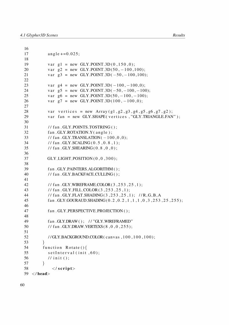
4.1 Glypher3D Scenes Results
1617 a n g l e + = 0 . 0 2 5 ;1819 v a r g1 = new GLY POINT 3D ( 0 , 1 5 0 , 0 ) ;20 v a r g2 = new GLY POINT 3D (50 , −100 ,100) ;21 v a r g3 = new GLY POINT 3D(−50 ,−100 ,100);2223 v a r g4 = new GLY POINT 3D(−100 ,−100 ,0) ;24 v a r g5 = new GLY POINT 3D(−50 ,−100 ,−100);25 v a r g6 = new GLY POINT 3D(50 ,−100 ,−100);26 v a r g7 = new GLY POINT 3D (100 , −100 ,0 ) ;2728 v a r v e r t i c e s = new Array ( g1 , g2 , g3 , g4 , g5 , g6 , g7 , g2 ) ;29 v a r f a n = new GLY SHAPE( v e r t i c e s , ”GLY TRIANGLE FAN” ) ;3031 / / f a n . GLY POINTS TOSTRING ( ) ;32 f a n . GLY ROTATION Y( a n g l e ) ;33 / / f a n . GLY TRANSLATION( −100 ,0 ,0 ) ;34 / / f a n . GLY SCALING ( 0 . 5 , 0 . 8 , 1 ) ;35 / / f a n . GLY SHEARING ( 0 . 8 , 0 , 0 ) ;3637 GLY LIGHT POSITION ( 0 , 0 , 3 0 0 ) ;3839 f a n . GLY PAINTERS ALGORITHM ( ) ;40 / / f a n . GLY BACKFACE CULLING ( ) ;4142 / / f a n . GLY WIREFRAME COLOR( 3 , 2 5 3 , 2 5 , 1 ) ;43 / / f a n . GLY FILL COLOR ( 3 , 2 5 3 , 2 5 , 1 ) ;44 / / f a n . GLY FLAT SHADING ( 3 , 2 5 3 , 2 5 , 1 ) ; / / R , G, B ,A45 f a n . GLY GOURAUD SHADING( 0 . 2 , 0 . 2 , 1 , 1 , 1 , 0 , 3 , 2 5 3 , 2 5 , 2 5 5 ) ;4647 f a n . GLY PERSPECTIVE PROJECTION ( ) ;4849 f a n .GLY DRAW ( ) ; / / ”GLY WIREFRAMED”50 / / f a n . GLY DRAW VERTEXS( 8 , 0 , 0 , 2 5 5 ) ;5152 / / GLY BACKGROUND COLOR( canvas , 1 0 0 , 1 0 0 , 1 0 0 ) ;53 }54 f u n c t i o n R o t a t e ( ) {55 s e t I n t e r v a l ( i n i t , 6 0 ) ;56 / / i n i t ( ) ;57 }58 < / s c r i p t>59 < / head>
60
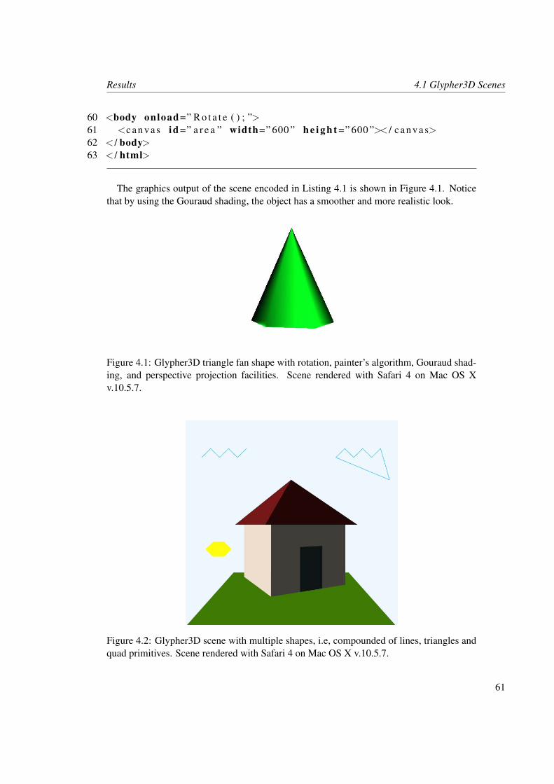
Results 4.1 Glypher3D Scenes
60 <body onload=” R o t a t e ( ) ; ”>61 <c an va s id =” a r e a ” width=” 600 ” h e i g h t =” 600 ”>< / c a nv a s>62 < / body>63 < / html>
The graphics output of the scene encoded in Listing 4.1 is shown in Figure 4.1. Noticethat by using the Gouraud shading, the object has a smoother and more realistic look.
Figure 4.1: Glypher3D triangle fan shape with rotation, painter’s algorithm, Gouraud shad-ing, and perspective projection facilities. Scene rendered with Safari 4 on Mac OS Xv.10.5.7.
Figure 4.2: Glypher3D scene with multiple shapes, i.e, compounded of lines, triangles andquad primitives. Scene rendered with Safari 4 on Mac OS X v.10.5.7.
61
4.2 Rendering Performance Results
Figure 4.2 shows a more complex Glypher3D scene, i.e. with multiple objects. In thatscene we use various Glypher3D graphics primitives. For the house, floor, and door we usequad primitives. The roof and sun are modeled using triangle fan primitives. Finally, theclouds are build up using two lines primitives: a line strip on the left and a line loop on theright.
An example of a Glypher3D web application is shown in Figure 4.3. In this applicationit is possible to see a fully functional web site with a Glypher3D scene, in which we caninteract with the object through various interaction buttons.
Figure 4.3: Fully functional Glypher3D web application running with Firefox 3.5 on MacOS X v.10.5.7.
4.2 Rendering Performance
Let us now compare how the Glypher3D library performs on different platforms (Windowsand Mac), and how it performs on the most common, canvas-compatible browsers, likeFirefox 3.5, Safari 4, Opera 10 Beta and Chrome 2, by comparing the rendering performancebetween an flat shaded object and an Gouraud shaded object. It is also tested the Glypher3Dlibrary on Internet Explorer 7 with the ExplorerCanvas plug-in release 3, and the rendering
62
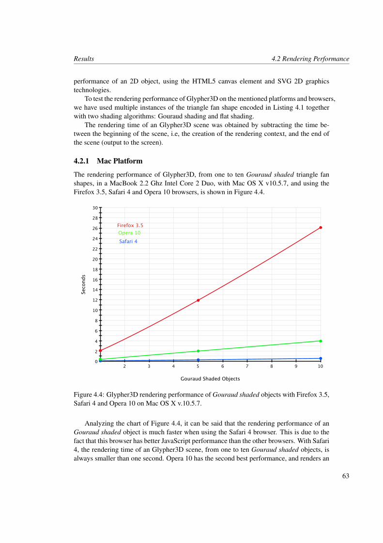
Results 4.2 Rendering Performance
performance of an 2D object, using the HTML5 canvas element and SVG 2D graphicstechnologies.
To test the rendering performance of Glypher3D on the mentioned platforms and browsers,we have used multiple instances of the triangle fan shape encoded in Listing 4.1 togetherwith two shading algorithms: Gouraud shading and flat shading.
The rendering time of an Glypher3D scene was obtained by subtracting the time be-tween the beginning of the scene, i.e, the creation of the rendering context, and the end ofthe scene (output to the screen).
4.2.1 Mac Platform
The rendering performance of Glypher3D, from one to ten Gouraud shaded triangle fanshapes, in a MacBook 2.2 Ghz Intel Core 2 Duo, with Mac OS X v10.5.7, and using theFirefox 3.5, Safari 4 and Opera 10 browsers, is shown in Figure 4.4.
10 2 3 4 5 6 7 8 9
30
0
2
4
6
8
10
12
14
16
18
20
22
24
26
28
Gouraud Shaded Objects
Seco
nds
Firefox 3.5Opera 10Safari 4
Figure 4.4: Glypher3D rendering performance of Gouraud shaded objects with Firefox 3.5,Safari 4 and Opera 10 on Mac OS X v.10.5.7.
Analyzing the chart of Figure 4.4, it can be said that the rendering performance of anGouraud shaded object is much faster when using the Safari 4 browser. This is due to thefact that this browser has better JavaScript performance than the other browsers. With Safari4, the rendering time of an Glypher3D scene, from one to ten Gouraud shaded objects, isalways smaller than one second. Opera 10 has the second best performance, and renders an
63
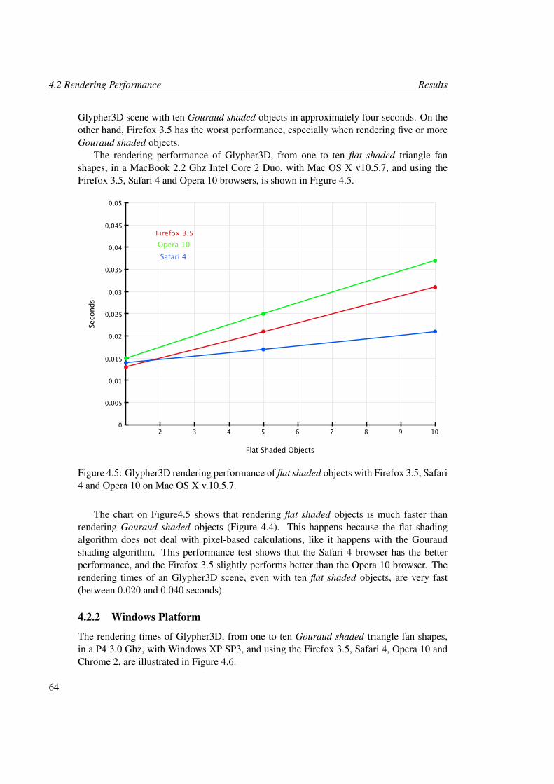
4.2 Rendering Performance Results
Glypher3D scene with ten Gouraud shaded objects in approximately four seconds. On theother hand, Firefox 3.5 has the worst performance, especially when rendering five or moreGouraud shaded objects.
The rendering performance of Glypher3D, from one to ten flat shaded triangle fanshapes, in a MacBook 2.2 Ghz Intel Core 2 Duo, with Mac OS X v10.5.7, and using theFirefox 3.5, Safari 4 and Opera 10 browsers, is shown in Figure 4.5.
10 2 3 4 5 6 7 8 9
0,05
0
0,005
0,01
0,015
0,02
0,025
0,03
0,035
0,04
0,045
Flat Shaded Objects
Seco
nds
Firefox 3.5Opera 10Safari 4
Figure 4.5: Glypher3D rendering performance of flat shaded objects with Firefox 3.5, Safari4 and Opera 10 on Mac OS X v.10.5.7.
The chart on Figure4.5 shows that rendering flat shaded objects is much faster thanrendering Gouraud shaded objects (Figure 4.4). This happens because the flat shadingalgorithm does not deal with pixel-based calculations, like it happens with the Gouraudshading algorithm. This performance test shows that the Safari 4 browser has the betterperformance, and the Firefox 3.5 slightly performs better than the Opera 10 browser. Therendering times of an Glypher3D scene, even with ten flat shaded objects, are very fast(between 0.020 and 0.040 seconds).
4.2.2 Windows Platform
The rendering times of Glypher3D, from one to ten Gouraud shaded triangle fan shapes,in a P4 3.0 Ghz, with Windows XP SP3, and using the Firefox 3.5, Safari 4, Opera 10 andChrome 2, are illustrated in Figure 4.6.
64
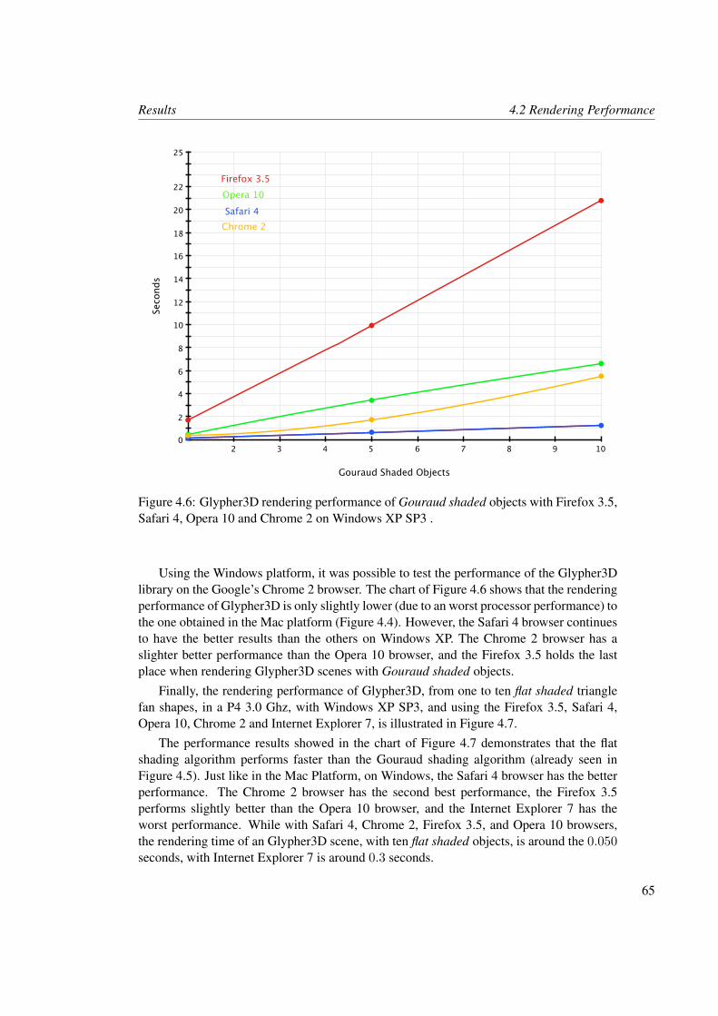
Results 4.2 Rendering Performance
10 2 3 4 5 6 7 8 9
25
0
2
4
6
8
10
12
14
16
18
20
22
Gouraud Shaded Objects
Seco
nds
Firefox 3.5Opera 10Safari 4
Chrome 2
Figure 4.6: Glypher3D rendering performance of Gouraud shaded objects with Firefox 3.5,Safari 4, Opera 10 and Chrome 2 on Windows XP SP3 .
Using the Windows platform, it was possible to test the performance of the Glypher3Dlibrary on the Google’s Chrome 2 browser. The chart of Figure 4.6 shows that the renderingperformance of Glypher3D is only slightly lower (due to an worst processor performance) tothe one obtained in the Mac platform (Figure 4.4). However, the Safari 4 browser continuesto have the better results than the others on Windows XP. The Chrome 2 browser has aslighter better performance than the Opera 10 browser, and the Firefox 3.5 holds the lastplace when rendering Glypher3D scenes with Gouraud shaded objects.
Finally, the rendering performance of Glypher3D, from one to ten flat shaded trianglefan shapes, in a P4 3.0 Ghz, with Windows XP SP3, and using the Firefox 3.5, Safari 4,Opera 10, Chrome 2 and Internet Explorer 7, is illustrated in Figure 4.7.
The performance results showed in the chart of Figure 4.7 demonstrates that the flatshading algorithm performs faster than the Gouraud shading algorithm (already seen inFigure 4.5). Just like in the Mac Platform, on Windows, the Safari 4 browser has the betterperformance. The Chrome 2 browser has the second best performance, the Firefox 3.5performs slightly better than the Opera 10 browser, and the Internet Explorer 7 has theworst performance. While with Safari 4, Chrome 2, Firefox 3.5, and Opera 10 browsers,the rendering time of an Glypher3D scene, with ten flat shaded objects, is around the 0.050seconds, with Internet Explorer 7 is around 0.3 seconds.
65
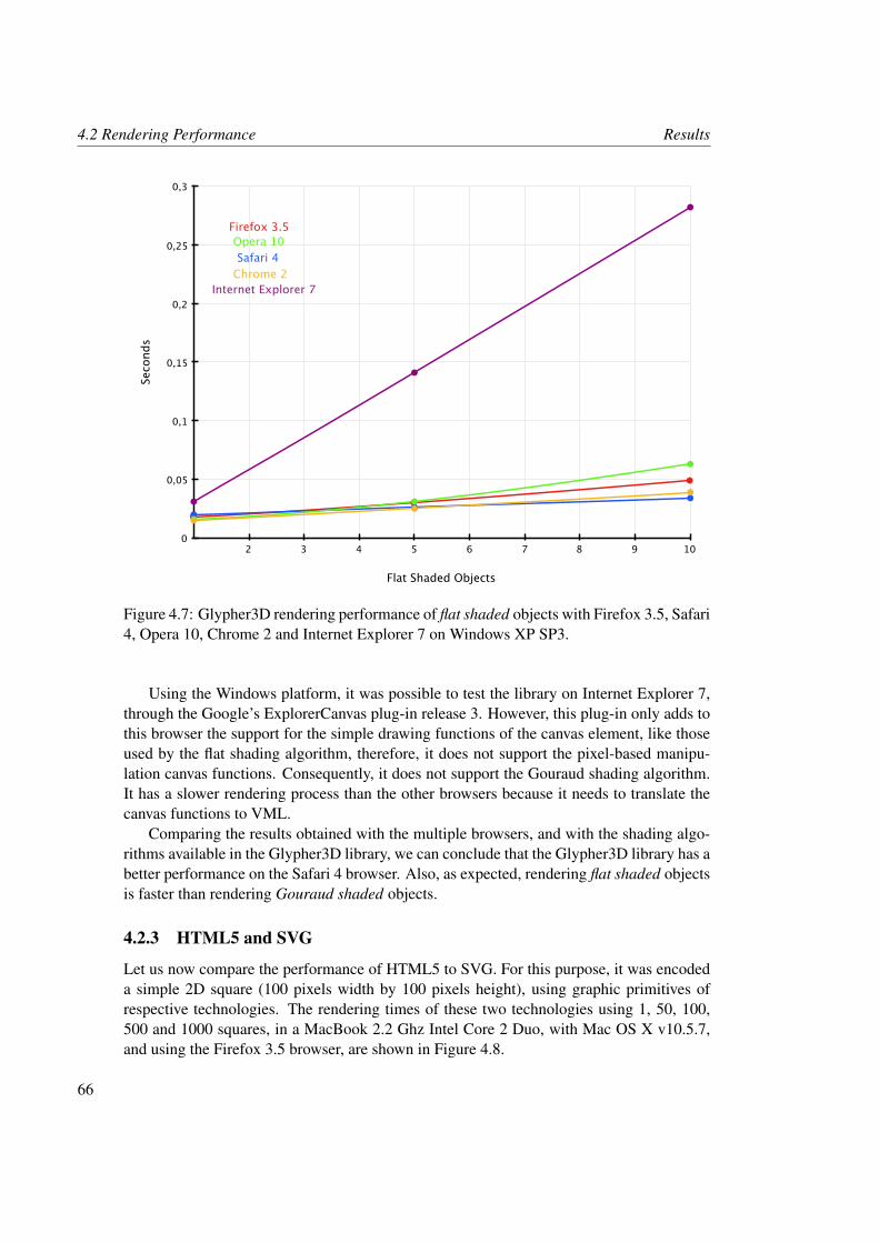
4.2 Rendering Performance Results
10 2 3 4 5 6 7 8 9
0,3
0
0,05
0,1
0,15
0,2
0,25
Flat Shaded Objects
Seco
nds
Firefox 3.5Opera 10Safari 4
Chrome 2Internet Explorer 7
Figure 4.7: Glypher3D rendering performance of flat shaded objects with Firefox 3.5, Safari4, Opera 10, Chrome 2 and Internet Explorer 7 on Windows XP SP3.
Using the Windows platform, it was possible to test the library on Internet Explorer 7,through the Google’s ExplorerCanvas plug-in release 3. However, this plug-in only adds tothis browser the support for the simple drawing functions of the canvas element, like thoseused by the flat shading algorithm, therefore, it does not support the pixel-based manipu-lation canvas functions. Consequently, it does not support the Gouraud shading algorithm.It has a slower rendering process than the other browsers because it needs to translate thecanvas functions to VML.
Comparing the results obtained with the multiple browsers, and with the shading algo-rithms available in the Glypher3D library, we can conclude that the Glypher3D library has abetter performance on the Safari 4 browser. Also, as expected, rendering flat shaded objectsis faster than rendering Gouraud shaded objects.
4.2.3 HTML5 and SVG
Let us now compare the performance of HTML5 to SVG. For this purpose, it was encodeda simple 2D square (100 pixels width by 100 pixels height), using graphic primitives ofrespective technologies. The rendering times of these two technologies using 1, 50, 100,500 and 1000 squares, in a MacBook 2.2 Ghz Intel Core 2 Duo, with Mac OS X v10.5.7,and using the Firefox 3.5 browser, are shown in Figure 4.8.
66
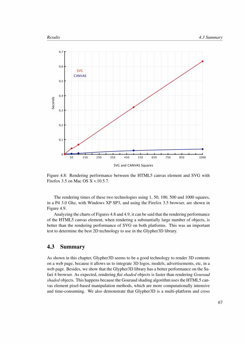
Results 4.3 Summary
1000 50 150 250 350 450 550 650 750 850
0,7
0
0,1
0,2
0,3
0,4
0,5
0,6
SVG and CANVAS Squares
Seco
nds
SVGCANVAS
Figure 4.8: Rendering performance between the HTML5 canvas element and SVG withFirefox 3.5 on Mac OS X v.10.5.7.
The rendering times of these two technologies using 1, 50, 100, 500 and 1000 squares,in a P4 3.0 Ghz, with Windows XP SP3, and using the Firefox 3.5 browser, are shown inFigure 4.9.
Analyzing the charts of Figures 4.8 and 4.9, it can be said that the rendering performanceof the HTML5 canvas element, when rendering a substantially large number of objects, isbetter than the rendering performance of SVG on both platforms. This was an importanttest to determine the best 2D technology to use in the Glypher3D library.
4.3 Summary
As shown in this chapter, Glypher3D seems to be a good technology to render 3D contentson a web page, because it allows us to integrate 3D logos, models, advertisements, etc, in aweb page. Besides, we show that the Glypher3D library has a better performance on the Sa-fari 4 browser. As expected, rendering flat shaded objects is faster than rendering Gouraudshaded objects. This happens because the Gouraud shading algorithm uses the HTML5 can-vas element pixel-based manipulation methods, which are more computationally intensiveand time-consuming. We also demonstrate that Glypher3D is a multi-platform and cross
67
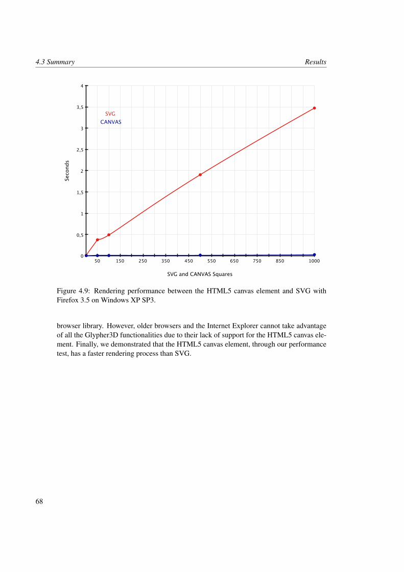
4.3 Summary Results
1000 50 150 250 350 450 550 650 750 850
4
0
0,5
1
1,5
2
2,5
3
3,5
SVG and CANVAS Squares
Seco
nds
SVGCANVAS
Figure 4.9: Rendering performance between the HTML5 canvas element and SVG withFirefox 3.5 on Windows XP SP3.
browser library. However, older browsers and the Internet Explorer cannot take advantageof all the Glypher3D functionalities due to their lack of support for the HTML5 canvas ele-ment. Finally, we demonstrated that the HTML5 canvas element, through our performancetest, has a faster rendering process than SVG.
68
Chapter 5
Conclusions and Future Work
This chapter explains how the research issues of this work have been solved, and discussesthe advantages and disadvantages in using the Glypher3D library, as well as points out inwhat aspects this library can be improved in the near future.
5.1 Conclusions
This dissertation shows that it is possible to create a Web3D graphics library without theobligation of installing any type of browser plug-ins or add-ons. In a way this means thatthe Glypher3D library provides an easier and more direct way of creating and interactingwith 3D contents directly on browser. Also, by not depending on these plug-ins or add-ons,it differentiates itself from all the Web3D technologies mentioned on Chapter 2. On theother hand, this also means that Glypher3D its a cross platform API in terms of operatingsystems and browser technologies.
By combining graphics algorithms encoded in JavaScript with the HTML5 canvas ele-ment drawing and rendering functions, it is a library accessible to those with some knowl-edge of JavaScript and HTML. To use this library it is only necessary to set up the canvastag and to call the library functions within a script in the HTML page (as shown in Chapter3). The HTML5 canvas element, proved to be a good technology to draw the Glypher3Dscenes within the canvas area, because it provides a good and simpler (than SVG) set ofdrawing functions, even at the level of individual pixels, and because has better renderingperformance than SVG, as shown in Figure 4.8. However, because it does not provide sceneDOM, interacting with the objects (for example, with mouse events) can be a complex task.Because the canvas tag it is just an HTML tag, any Glypher3D scene is full integrated onthe web page.
The main drawback of the HTML5 canvas element, and also of the Glypher3D library, isits incompatibility with Internet Explorer, however, it is compatible with all the other majorbrowsers, like Firefox, Safari, Opera and Chrome. To take advantage of all the HTML5canvas element functions, it is recommended to use the latest browsers versions. This is dueto the fact of the HTML5 markup language is a recent technology and is still in development.So, to take full advantage of the Glypher3D library, we recommend the following browsers
69
5.2 Future Work Conclusions and Future Work
and versions: Firefox (3+), Safari (4+), Opera (10+) and Chrome (2+). To make the HTML5canvas element accessible (only the simple drawing functions) to Internet Explorer, theExplorerCanvas plug-in was developed by Google (see Chapter 3).
All the technologies mentioned in Chapter 2, take advantage of software or hardwareacceleration (OpenGL or Directx), what allows them to provide fluid and high detailed 3Denvironments. On the other hand, Glypher3D does not use any plug-in to access the men-tioned graphical engines, and due to the fact that all its algorithms are encoded in JavaScript(processed on the client machine), it has slower rendering performance than those Web3Dtechnologies, especially when rendering complex objects with Gouraud shading (the onlyshading algorithm with pixel-based calculations).
However, when rendering simple objects, with color or shading algorithms that do notuse the HTML5 canvas element pixel-based manipulation methods directly, Glypher3D iseffective and the rendering is fast and fluid. The access to an web page with an Glypher3Dscene is instantaneous and direct. On the other hand, a web page with other Web3D tech-nologies (plug-ins or add-ons dependent) have higher loading times. With the results ob-tained in Chapter 4, it is possible to conclude that the Glypher3D library has a better perfor-mance on the Safari 4 browser, and that the rendering performance of an Glypher3D sceneusing flat shaded objects is much better than an Glypher3D scene using Gouraud shadedobjects. Therefore, it can be said that Glypher3D is a good tool to directly draw and ma-nipulate simple 3D scenes on browser. However, it cannot provide the level of realism andrendering speed of the studied Web3D technologies yet.
Only recently, we were advised about the existence of another Web3D library calledOpenJSGL [33] with the same purposes and technologies (plug-in free through the HTML5canvas element) of Glypher3D. However, while this library replicates the facilities of OpenGL,in order to ease the programming process to OpenGL developers, Glypher3D aims at cre-ating graphics algorithms from scratch, but as simple and intuitive as possible, providing adifferent way in the creation and manipulation of an 3D scene. Notice that when this dis-sertation was proposed, we were unaware of the existence of OpenJSGL library. Besides,with the rapid growth of the Internet and browser capabilities, new technologies to deliver3D contents over the web, without the obligation to install browser plug-ins or add-ons, areemerging at a rapid rate.
5.2 Future Work
Glypher3D can be improved in some aspects. For now, it does not allow to load or importmodels from external files, as it happens with other Web3D technologies. Consequently,all the models have to be created by programming in JavaScript. Importing models wouldsave a lot of time, especially in the creation of very complex models. Also, the use oftext, textures and a dynamic viewer position, would provide another level of realism to theGlypher3D scenes. We believe that the Gouraud shading algorithm can be improved toprovide a better visualization and rendering speed of 3D scenes.
Glypher3D is a library that takes advantage of the HTML5 canvas element 2D renderingcontext to draw 3D scenes. However, it is expected that in the future a canvas 3D rendering
70
Conclusions and Future Work 5.2 Future Work
context will be introduced in HTML. With this 3D context accessible to JavaScript, devel-opers may create 3D contents without the need of the additional libraries that nowadays addthe third dimension to the web.
Also, very recently, it was announced by the Khronos Group (consortium that developsOpenGL standard) that efforts are being made to create a new 3D standard for the web with-out browser plug-ins. For that, it was formed the WebGL workgroup to define a JavaScriptbinding to OpenGL ES 2.0, which will make possible for browsers to render 3D contentsrapidly without plug-ins.
71

Bibliography
[1] Adobe. Actionscript Technology Center. http://www.adobe.com/devnet/actionscript/, 2009.
[2] Adobe. Exploring the New 3D Features in Flash CS4 Professional. http://www.adobe.com/devnet/flash/articles/3d_support.html, 2009.
[3] Adobe. Flash Lite: Features. http://www.adobe.com/products/flashlite/features/, 2009.
[4] Adobe. Flash Player 10: Complete Features. http://www.adobe.com/products/flashplayer/features/all_features/, 2009.
[5] Adobe. What is the Difference Between Shockwave and Flash. http://kb2.adobe.com/cps/139/tn_13971.html, 2009.
[6] Ajax3D. Ajax3d.org - Showcases and Tutorials. http://www.ajax3d.org/content/t2/indexa.html, 2009.
[7] Dave Astle and Kevin Hawkins. Beginning OpenGL Game Programming. CengageLearning, 2004.
[8] Chris Bishop, Mark Paruzel, Andor Salga, Andrew Smith, and Cathy Leung. Canvas3D JS Library. http://www.c3dl.org/, 2009.
[9] Don Brutzman and Leonard Daly. X3D: Extensible 3D Graphics for Web Authors.Morgan Kaufmann, 2007.
[10] Don Brutzman and Leonard Daly. X3D: Extensible 3D Graphics Standard. IEEESignal Processing Magazine, pages 130–135, November 2007.
[11] Mozilla Development Center. The Canvas Element - Basic Usage. https://developer.mozilla.org/en/Canvas_tutorial/, 2009.
[12] Luca Chittaro and Roberto Ranon. Web3D Technologies in Learning, Education andTraining: Motivations, Issues, Opportunities. In Computers & Education, pages 3–18.Elsevier Science Ltd, June 2007.
73
BIBLIOGRAPHY
[13] Sophie 3D Engine. Sophie 3D Player - Flash 3D Engine. http://www.sophie3d.com/, 2009.
[14] Kenneth C. Finney. 3D Game Programming All in One. Cengage Learning, 2004.
[15] Flash and Math. Simple 3D Dynamic Drawing in Flash CS4. http://www.flashandmath.com/flashcs4/cs4simple3d/index.html, 2009.
[16] James D. Foley, Andries Van Dam, Steven K. Feiner, and John F. Hughes. ComputerGraphics: Principles and Practice. Addison-Wesley, 1995.
[17] Google. Explorercanvas HTML5 Canvas for Internet Explorer. http://code.google.com/p/explorercanvas/, 2009.
[18] Google. O3D Demos and Samples. http://code.google.com/intl/pt-PT/apis/o3d/docs/samplesdirectory.html, 2009.
[19] Google. O3D Technical Overview. http://code.google.com/intl/pt-PT/apis/o3d/docs/techoverview.html, 2009.
[20] Khronos Group. COLLADA - 3D Asset Exchange Schema. http://www.khronos.org/collada/, 2009.
[21] Khronos Group. OpenGL - The Industry’s Foundation for High Performance Graph-ics. http://www.khronos.org/opengl/, 2009.
[22] Xichun Jennifer Guo. Phong Shading and Gouraud Shading. http://www.nbb.cornell.edu/neurobio/land/OldStudentProjects/cs490-95to96/guo/report.html, 1996.
[23] HTML5. The Canvas Element. http://www.whatwg.org/specs/web-apps/current-work/multipage/the-canvas-element.html,2009.
[24] Java.Net. Java3D Enigma Cipher Machine Applet. https://enigma.dev.java.net/enigma-applet.html, 2009.
[25] Nigel W. John. The Impact of Web3D Technologies on Medical Education and Train-ing. In Computers & Education, pages 19–31. Elsevier Science Ltd, June 2007.
[26] Neal Leavitt. Browsing the 3D Web. IEEE Computer Society Press, pages 22–24,September 2006.
[27] Catherine Leung, Andor Salga, and Andrew Smith. Canvas 3D JS Library. In Proceed-ings of the 2008 Conference on Future Play: Research, Play, Share, pages 274–275.ACM, November 2008.
74
BIBLIOGRAPHY
[28] Francisco Luengo, Mariela Contreras, Aurely Leal, and Andres Iglesias. Interactive3D Graphics Applications Embedded in Web Pages. In Proceedings of the ComputerGraphics, Imaging and Visualization, pages 434–440. IEEE Computer Society, Au-gust 2007.
[29] Jeffrey J. McConnell. Computer Graphics: Theory Into Practice. Jones and BartlettPublishers, 2004.
[30] Microsoft. DirectX: Advanced Graphics on Windows. http://msdn.microsoft.com/en-us/directx/default.aspx, 2009.
[31] David R. Nadeau. Building Virtual Worlds with VRML. IEEE Computer Graphicsand Applications, pages 18–29, April 1999.
[32] Octaga. Octaga VRML and X3D Examples. http://www.octaga.com/, 2009.
[33] OpenJSGL. http://openjsgl.sourceforge.net/openjsgl/doc/index.html, 2009.
[34] Tony Parisi. Ajax3D: The Open Platform for Rich 3D Web Applications. Whitepaper.Media Machines, Inc., August 2006.
[35] 3D Technologies RD. 3D Markup Language for Web - Open Source Platform forCreating 3D and 2D Interactive Web Content. http://www.3dmlw.com/, 2008.
[36] Chad F. Salisbury, Steven D. Farr, and Jason A. Moore. Web-based Simulation Visu-alization using Java3D. In Proceedings of the 31st Conference on Winter simulation,pages 1425–1429. ACM, January 1999.
[37] Sun. Java Plug-in Technology. http//java.sun.com/products/plugin,2009.
[38] Vladimir Vukicevic. SVG and Canvas: Graphics for Web Apps. http://people.mozilla.com/˜vladimir/xtech2006/, 2006.
[39] Vladimir Vukicevic. Canvas 3D: GL Power, Web-style. http://blog.vlad1.com/2007/11/26/canvas-3d-gl-power-web-style/, 2007.
[40] Vladimir Vukicevic. Canvas 3D. http://blog.vlad1.com/canvas-3d/,2008.
[41] Vladimir Vukicevic. Canvas 3D Extension Update. http://blog.vlad1.com/2009/03/28/canvas-3d-extension-update-2/, 2009.
[42] W3C. Document Object Model (DOM). http://www.w3.org/DOM/, 2009.
[43] Aaron E. Walsh and Mikael Bourges-Sevenier. Core WEB 3D. Prentice Hall PTR,2000.
75

Appendix A
Glossary
In this appendix is given the description of frequently used abbreviations.
3DMLW 3D Markup Language for Web
3DS 3ds Max
Ajax Asynchronous JavaScript and XML
API Application Programming Interface
ASCII American Standard Code for Information Interchange
AVM ActionScript Virtual Machine
C3DL Canvas 3D JS Library
COLLADA COLLAborative Design Activity
CSS Cascading Style Sheet
DOM Document Object Model
DIS Distributed Interactive Simulation
H-Anim Humanoid Animation
HTML HyperText Markup Language
ISO International Organization for Standardization
JIT Just In Time compiler
JRE Java Runtime Environment
JVM Java Virtual Machine
MOCAP Motion Capture
77
Glossary
NURBS Non-Uniform Rational Bezier Spline
RIA Rich Internet Applications
SAI Scene Authoring Interface
SVG Scalable Vector Graphics
VML Vector Markup Language
VRML Virtual Reality Markup Language
W3C World Wide Web Consortium
WWW World Wide Web
X3D eXtensible 3D
XML eXtensible Markup Language
78
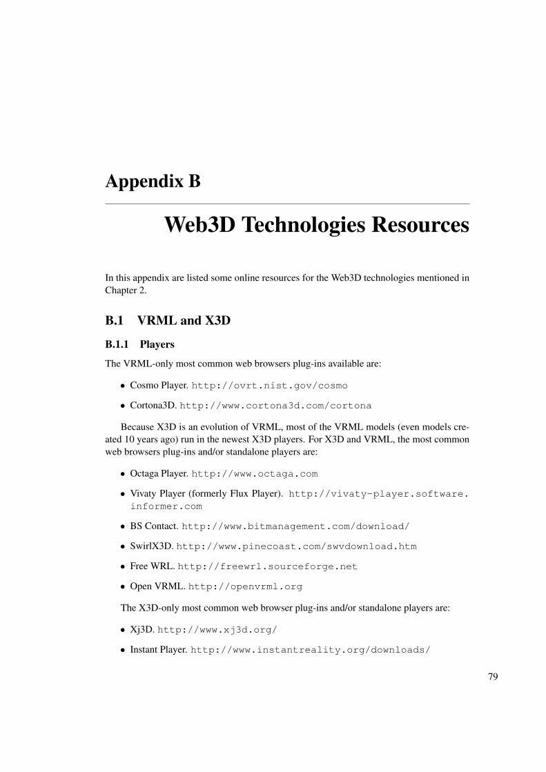
Appendix B
Web3D Technologies Resources
In this appendix are listed some online resources for the Web3D technologies mentioned inChapter 2.
B.1 VRML and X3D
B.1.1 Players
The VRML-only most common web browsers plug-ins available are:
• Cosmo Player. http://ovrt.nist.gov/cosmo
• Cortona3D. http://www.cortona3d.com/cortona
Because X3D is an evolution of VRML, most of the VRML models (even models cre-ated 10 years ago) run in the newest X3D players. For X3D and VRML, the most commonweb browsers plug-ins and/or standalone players are:
• Octaga Player. http://www.octaga.com
• Vivaty Player (formerly Flux Player). http://vivaty-player.software.informer.com
• BS Contact. http://www.bitmanagement.com/download/
• SwirlX3D. http://www.pinecoast.com/swvdownload.htm
• Free WRL. http://freewrl.sourceforge.net
• Open VRML. http://openvrml.org
The X3D-only most common web browser plug-ins and/or standalone players are:
• Xj3D. http://www.xj3d.org/
• Instant Player. http://www.instantreality.org/downloads/
79
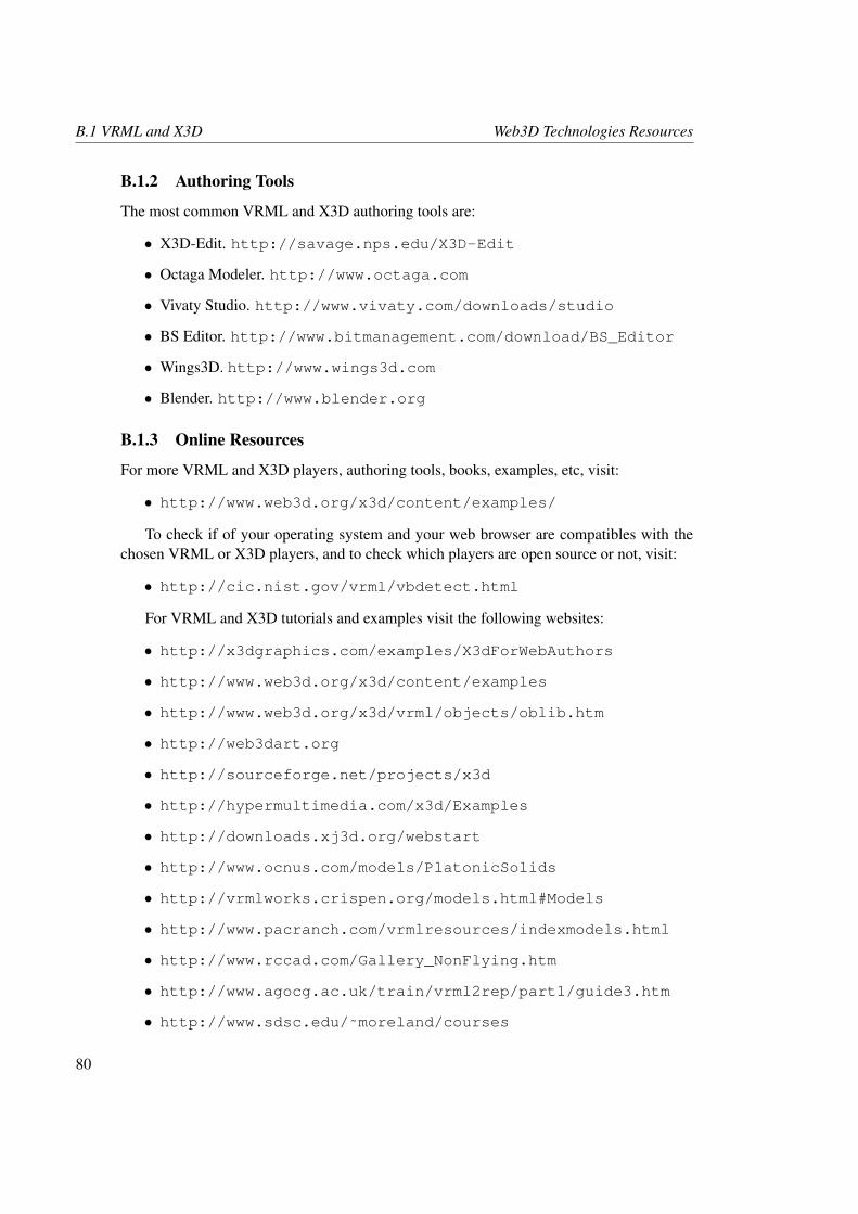
B.1 VRML and X3D Web3D Technologies Resources
B.1.2 Authoring Tools
The most common VRML and X3D authoring tools are:
• X3D-Edit. http://savage.nps.edu/X3D-Edit
• Octaga Modeler. http://www.octaga.com
• Vivaty Studio. http://www.vivaty.com/downloads/studio
• BS Editor. http://www.bitmanagement.com/download/BS_Editor
• Wings3D. http://www.wings3d.com
• Blender. http://www.blender.org
B.1.3 Online Resources
For more VRML and X3D players, authoring tools, books, examples, etc, visit:
• http://www.web3d.org/x3d/content/examples/
To check if of your operating system and your web browser are compatibles with thechosen VRML or X3D players, and to check which players are open source or not, visit:
• http://cic.nist.gov/vrml/vbdetect.html
For VRML and X3D tutorials and examples visit the following websites:
• http://x3dgraphics.com/examples/X3dForWebAuthors
• http://www.web3d.org/x3d/content/examples
• http://www.web3d.org/x3d/vrml/objects/oblib.htm
• http://web3dart.org
• http://sourceforge.net/projects/x3d
• http://hypermultimedia.com/x3d/Examples
• http://downloads.xj3d.org/webstart
• http://www.ocnus.com/models/PlatonicSolids
• http://vrmlworks.crispen.org/models.html#Models
• http://www.pacranch.com/vrmlresources/indexmodels.html
• http://www.rccad.com/Gallery_NonFlying.htm
• http://www.agocg.ac.uk/train/vrml2rep/part1/guide3.htm
• http://www.sdsc.edu/˜moreland/courses
80
Web3D Technologies Resources B.2 Java3D
B.2 Java3D
B.2.1 Online Resources
To download the Java3D API, visit:
• http://java.sun.com/javase/technologies/desktop/java3d
The Java Runtime Environment and Java Plug-in is available at:
• http://java.sun.com/javase/downloads/index.jsp
For Java3D online examples, visit:
• https://java3d.dev.java.net
• http://www.apas.com/pzt/java3d/index.html
• http://www.java3d.org
To help you in Java3D programming visit:
• http://java.sun.com/developer/onlineTraining/java3d
• http://www.java3d.org/tutorial.doc
• http://www.javaworld.com/javaworld/jw-12-1998/jw-12-media.html?page=1
• http://www.tecgraf.puc-rio.br/˜ismael/Cursos/Cidade_CG/labs/Java3D
• http://java3d.j3d.org/tutorials/index.html
B.3 Flash 3D
B.3.1 Flash engines
Flash 2.5D AS3 isometric engines:
• Ffilmation. http://www.ffilmation.org/website
• Alternativa Platform. http://blog.alternativaplatform.com/en
Flash 3D engines:
• Papervision 3D. http://www.papervision3d.org
• Electric 3D. http://www.electricoyster.com
81
B.3 Flash 3D Web3D Technologies Resources
• Away 3D. http://away3d.com
• Sophie 3D. http://www.sophie3d.com/website/index_en.php
• Alternativa Platform. http://blog.alternativaplatform.com/en
• Sandy 3D. http://www.flashsandy.org
• Wire Engine 3D. http://osflash.org/we3d
Flash 3D game engines:
• PaperWorld 3D. http://paperworld3d.com
• SWFZ. http://drawlogic.com/category/swfz
Flash 3D vector engine:
• Five 3D. http://five3d.mathieu-badimon.com
Flash 3D physics engine:
• WOW Engine. http://seraf.mediabox.fr/wow-engine
3D Flash components:
• FreeSpin 3D. http://www.freespin3d.com/Home.aspx
Flash 3D animation framework:
• Cast 3D. http://www.cast3d.com
Flash 3D modeler:
• G-Nero. http://www.g-nero.com
B.3.2 Online Resources
To download the Flash Player 10 visit:
• http://get.adobe.com/br/flashplayer/
For proprietary and open-source Flash authoring tools visit:
• http://www.adobe.com/br/products/flash
• http://osflash.org/open_source_flash_projects
Some Flash 3D examples, as well as full Flash 3D web environments can be seen at:
82
Web3D Technologies Resources B.4 C3DL
• http://www.ecodazoo.com
• http://www.onemotion.com/flash/spider
• http://strille.net/works/as3/raytracer
• http://blog.alternativaplatform.com/en/
• http://www.electricoyster.com/electric3d/index.html
Some Flash 3D tutorials are available at:
• http://theflashblog.com/?cat=13
• http://www.adobe.com/devnet/flash/3d_animation.html
• http://www.flashandmath.com/flashcs4
• http://www.tutorialized.com/tutorials/Flash/3D/1
• http://www.kirupa.com/developer/actionscript/3dindex.htm
• http://www.flashmagazine.com/Tutorials/detail/flash_3d_basics
• http://www.senocular.com/flash/tutorials/as3withflashcs3
B.4 C3DL
B.4.1 Online Resources
The download of the Mozilla Firefox Canvas 3D add-on is available at:
• https://addons.mozilla.org/en-US/firefox/addon/7171
For extra information about the experimental Canvas 3D add-on to Firefox, visit:
• http://groups.google.com/group/canvas-3d
• http://blog.vlad1.com/category/mozilla/canvas-3d
• http://people.mozilla.com/˜vladimir/canvas3d/docs/
• http://people.mozilla.com/˜vladimir/canvas3d/examples/
• https://labs.mozilla.com/forum/?CategoryID=9
The C3DL library, as well as tutorials, development news, documentation and examplesare available at C3DL home page:
• http://www.c3dl.org
83
B.5 Ajax3D Web3D Technologies Resources
B.5 Ajax3D
B.5.1 Online Resources
Detailed information about Ajax3D, as well as examples, tutorials and discussion forums,are available at Ajax3D home page:
• http://www.ajax3d.org
B.6 3DMLW
B.6.1 Online Resources
To download the 3DMLW web browser plug-in, to see more detailed information, tutorialsand examples of 3DMLW, visit:
• http://www.3dmlw.com
To edit 3DMLW documents, visit the 3DMLW editor page:
• http://www.quantumhog.com
B.7 O3D
B.7.1 Online Resources
The O3D web browser plug-in is available at:
• http://tools.google.com/dlpage/o3d
For samples and detailed information about O3D visit:
• http://code.google.com/intl/pt-PT/apis/o3d
• http://google-code-updates.blogspot.com
• http://groups.google.com/group/o3d-discuss
• http://o3d.blogspot.com
• http://www.o3dexamples.com
To create 3D models you can use:
• http://sketchup.google.com
84


![[UniteKorea2013] The Unity Rendering Pipeline](https://static.fdocuments.us/doc/165x107/558c6a7bd8b42ad9508b4779/unitekorea2013-the-unity-rendering-pipeline.jpg)