RelayAux - Schneider Electric · relay drops off in those cases, providing the related signs and...
28
Accessories 01 RelayAux Auxiliary relays for tripping and control applications CUSTOMER BENEFITS • Designed to allow continuous operation even in high temperature ambient, within the whole voltage range • High level of electrical insulation between input and output circuits • Self-cleaning contacts • High speed operation • Sturdy design • High protection degree (IP40), with transparent cover, making them suitable for use in salty and tropical atmospheres • In compliance with the most demanding test standards: IEC, EN, IEEE and bearing the CE mark • Simplicity of installation (plug-in relays in a wide range of sockets with different installation configurations) • No maintenance The auxiliary relays range offers varying levels of functionality to best suit the tripping and control applications requirements, and allows the customers to choose the most cost effective solution to their various applications. The design, durability and quality of the RelayAux make them suitable for high responsibility controls such as: • Electrical utilities • Power generation • Electrical substations • Transportation • Industry - Oil & Gas - Food & beverage - Water - Mining, Minerals, metals ... PM102996
-
Upload
hoangquynh -
Category
Documents
-
view
284 -
download
1
Transcript of RelayAux - Schneider Electric · relay drops off in those cases, providing the related signs and...
Accessories 01
RelayAuxAuxiliary relays for tripping and control applications
CUSTOMER BENEFITS
• Designed to allow continuous operation even in high temperature ambient, within the whole voltage range
• High level of electrical insulation between input and output circuits
• Self-cleaning contacts
• High speed operation
• Sturdy design
• High protection degree (IP40), with transparent cover, making them suitable for use in salty and tropical atmospheres
• In compliance with the most demanding test standards: IEC, EN, IEEE and bearing the CE mark
• Simplicity of installation (plug-in relays in a wide range of sockets with different installation configurations)
• No maintenance
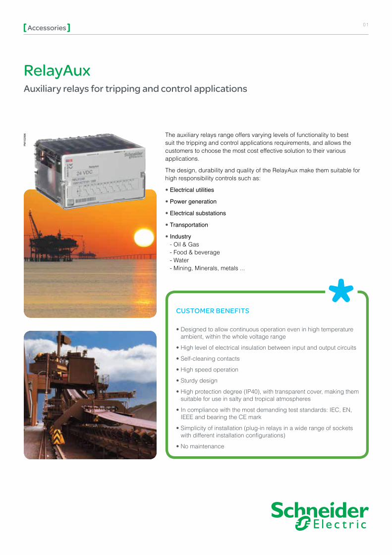
The auxiliary relays range offers varying levels of functionality to best suit the tripping and control applications requirements, and allows the customers to choose the most cost effective solution to their various applications.
The design, durability and quality of the RelayAux make them suitable for high responsibility controls such as:
• Electrical utilities
• Power generation
• Electrical substations
• Transportation
• Industry - Oil & Gas - Food & beverage - Water - Mining, Minerals, metals ...
PM
1029
96

RelayAuxAccessories 02
Range of products
INSTANTANEOUS TRIP RELAYS Instantaneous trip relays, whose contacts change instantaneously from the rest position to the working position when the coil is energized. The contacts return to the rest position when the coil is no longer energized.
This range includes relays with 2 and 4 contacts, with standard operating times (20 ms) or fast operating time (8 ms), depending on the model.
TRIP AND LOCKOUT RELAYSTrip relays with 2 stable positions for the output contacts. Depending on which coil is energized, the contacts will change from one position to the other. The design of the RelayAux has no consumption in permanence, and prevents both coils from being energized simultaneously.
This range includes relays with 4 and 8 contacts, with operating times below 10 ms, depending on the model, and possibility of manual reset. The position change is made with 2 sets of coils with separated entrances, and with breaking-flame contacts for each set of coils.
TIME-LAG RELAYS Time-lag relays allow 16 time settings (from 30 ms to 99 h) and 10 different functions (all of it being easily adjustable from the front of the relay):
• Pick-up timing• Pick-up timing acceleration• Drop-out timing• Flashing timing• Special timingThis auxiliary relay with 4 contacts makes possible direct action on HV and MV switchgear.
PM
1029
96
PM
1029
96
PM
1035
18
03RelayAuxAccessories
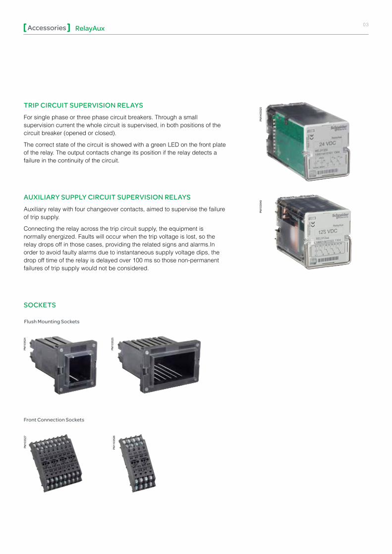
TRIP CIRCUIT SUPERVISION RELAYSFor single phase or three phase circuit breakers. Through a small supervision current the whole circuit is supervised, in both positions of the circuit breaker (opened or closed).
The correct state of the circuit is showed with a green LED on the front plate of the relay. The output contacts change its position if the relay detects a failure in the continuity of the circuit.
AUXILIARY SUPPLY CIRCUIT SUPERVISION RELAYSAuxiliary relay with four changeover contacts, aimed to supervise the failure of trip supply.
Connecting the relay across the trip circuit supply, the equipment is normally energized. Faults will occur when the trip voltage is lost, so the relay drops off in those cases, providing the related signs and alarms.In order to avoid faulty alarms due to instantaneous supply voltage dips, the drop off time of the relay is delayed over 100 ms so those non-permanent failures of trip supply would not be considered.
SOCKETS
Front Connection Sockets
PM
1103
526
PM
1035
27
Flush Mounting Sockets
PM
1035
24
PM
1035
25
PM
1403
520
PM
1035
49
RelayAuxAccessories 04
Instantaneous Trip relays
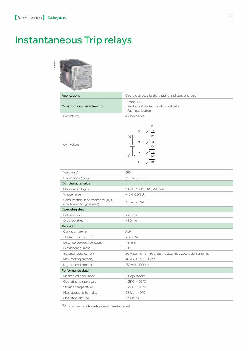
Applications Operate directly to the tripping and control circuit
Construction characteristics• Front LED• Mechanical contact position indicator• Push test button
Contacts no. 4 Changeover
Connections
711
12
13
9
14
10
5
3
1
2
( –)
4 8
6
( +)
Weight (g) 250
Dimensions (mm) 42.5 x 50.4 x 72
Coil characteristicsStandard voltages 24, 30, 48, 110, 125, 220 Vdc
Voltage range +10% -20%
Consumption in permanence ( ) (Low burden & High burden) 3,9 W; 6,6 VA
Operating timePick-up time < 20 ms
Drop-out time < 50 ms
ContactsContact material AgNi
Contact resistance 30 m
Distance between contacts 1,8 mm
Permanent current 10 A
Instantaneous current 30 A during 1 s / 80 A during 200 ms / 200 A during 10 ms
Max. making capacity 40 A / 0,5 s / 110 Vdc
opened contact 250 Vdc / 400 Vac
Performance dataMechanical endurance 10 operations
Operating temperature - 25°C + 70°C
Storage temperature - 25°C + 70°C
Max. operating humidity 93 % / + 40°C
Operating altitude <2000 m
Guarantee data for relays just manufactured
PM
1029
90

RelayAuxAccessories 05
Instantaneous Fast Trip relays
ApplicationsIntended for tripping applications where high demanding requirements in operating time and breaking capacity are needed, that is the case of tripping HV and MV circuit breakers
Construction characteristics
• Diode in parallel with the coil• Front LED• Mechanical contact position indicator• Trip flag
Contacts no. 4 Changeover
Connections
1
2
( –)
( +)
711
12
13
14
10
5
3
4 8
9
6
Weight (g) 250
Dimensions (mm) 42.5 x 50.4 x 72
Coil characteristicsStandard voltages 24, 30, 48, 110, 125, 220 Vdc
Voltage range +10% -20%
Consumption (Low burden & High burden)
in permanence ( ) 1 W
Peak 96 Vdc 0,8 A / 20 ms
Peak 96 Vdc 0,3 A / 20 ms
Operating timePick-up time < 8 ms
Drop-out time < 40 ms
ContactsContact material AgNi
Contact resistance 30 m
Distance between contacts 1,2 mm
Permanent current 10 A
Instantaneous current 30 A during 1 s / 80 A during 200 ms / 200 A during 10 ms
Max. making capacity 40 A / 0,5 s / 110 Vdc
opened contact 250 Vdc / 400 Vac
Performance dataMechanical endurance 10 operations
Operating temperature - 25°C + 70°C
Storage temperature - 25°C + 70°C
Max. operating humidity 93 % / + 40°C
Operating altitude <2000 m
Guarantee data for relays just manufactured
PM
1029
94

RelayAuxAccessories 06
ApplicationsIntended for tripping applications where high demanding requirements in operating time and breaking capacity are needed, that is the case of tripping HV and MV circuit breakers
Construction characteristics
• Diode in parallel with the coil• Front LED• Mechanical contact position indicator• Trip flag• Push test button (refer to the Order Code number)
Contacts no. 8 Changeover
Connections
3
1
a
d
( –)
( +)
2
4
5
6
7
8
1110
202130314041505160
70
80
61
71
81
Weight (g) 500
Dimensions (mm) 82.5 x 50.4 x 72
Coil characteristicsStandard voltages 24, 30, 48, 110, 125, 220 Vdc
Voltage range +10% -20%
Consumption (Low burden & High burden)
in permanence ( ) 1.4 W
Peak 96 Vdc 0,8 A / 20 ms
Peak 96 Vdc 0,3 A / 20 ms
Operating timePick-up time < 8 ms
Drop-out time < 40 ms
ContactsContact material AgNi
Contact resistance 30 m
Distance between contacts 1,2 mm
Permanent current 10 A
Instantaneous current 30 A during 1 s / 80 A during 200 ms / 200 A during 10 ms
Max. making capacity 40 A / 0,5 s / 110 Vdc
opened contact 250 Vdc / 400 Vac
Performance dataMechanical endurance 10 operations
Operating temperature - 25°C + 70°C
Storage temperature - 25°C + 70°C
Max. operating humidity 93 % / + 40°C
Operating altitude <2000 m
Guarantee data for relays just manufactured
Instantaneous Fast Trip relays (cont.)
PM
1029
96

RelayAuxAccessories 07
Fast Trip and Lockout relays
Applications Intended for tripping and locking applications where high quality requirements in operating time and breaking capacity are needed.
Construction characteristics
• Diode in parallel with the coil• Mechanical contact position• Electrical reset• Manual reset
Contacts no. 4 Changeover
Connections
10149
138
712
11
6
5
4
3
B1
12-
+
+
Set
Reset
Weight (g) 300
Dimensions (mm) 45 x 45 x 96.5
Coil characteristicsStandard voltages 24, 30, 48, 110, 125, 220 Vdc
Voltage range +10% -20%
Consumption only in commutation
Low burden 23 W (peak)
High burden125 Vdc = < 100 W (peak)
220 Vdc = < 150 W (peak)
Operating timePick-up time < 10 ms
ContactsContact material AgNi
Distance between contacts 1.8 mm
Permanent current 10 A
Instantaneous current 80 A during 200 ms / 200 A during 10 ms
Max. making capacity 40 A / 0,5 s / 110 Vdc
opened contact 250 Vdc / 400 Vac
Performance dataMechanical endurance 10 operations
Operating temperature - 25°C + 70°C
Storage temperature - 25°C + 70°C
Max. operating humidity 93 % / + 40°C
Operating altitude < 2000 m
PM
1035
09

RelayAuxAccessories 08
Fast Trip and Lockout relays (cont.)
Applications Intended for tripping and locking applications where high quality requirements in operating time and breaking capacity are needed.
Construction characteristics
• Diode in parallel with the coil• Mechanical contact position• Electrical reset• Manual reset (Refer to the Order Code number)
Contacts no. 8 Changeover
Connections
11
51
21
61
20
60
31
71
41
81
30
70
40
80
1
5
2
6
3
7
4
8
a
c
b
d
+
+
-
-
Set
Reset50
10
Weight (g) 600
Dimensions (mm) 90 x 50 x 100.5
Coil characteristicsStandard voltages 24, 30, 48, 110, 125, 220 Vdc
Voltage range +10% -20%
Consumption only in commutation
Low burden 35.5 W (peak)
High burden125 Vdc = < 100 W (peak)
220 Vdc = < 150 W (peak)
Operating timePick-up time < 10 ms
ContactsContact material AgNi
Distance between contacts 1.8 mm
Permanent current 10 A
Instantaneous current 80 A during 200 ms / 200 A during 10 ms
Max. making capacity 40 A / 0,5 s / 110 Vdc
opened contact 250 Vdc / 400 Vac
Performance dataMechanical endurance 10 operations
Operating temperature - 25°C + 70°C
Storage temperature - 25°C + 70°C
Max. operating humidity 93 % / + 40°C
Operating altitude < 2000 m
PM
1035
13

RelayAuxAccessories 09
Time-lag relay
Applications Electrical command timing
Construction characteristics
• Front LEDs: - Activation LED - Timing LED
• Control voltage input
Contacts no. 4 Changeover
Connections
TIMER
B1
2-
3
4
5
6
A1
1+
117
128
139
1410
2(-)( )
(+)( )
(+)( )
1
B1
Weight (g) 265
Dimensions (mm) 42.5 x 50.4 x 96.6
Coil characteristicsStandard voltages 24, 30, 48, 110, 125, 220 Vdc / Vac (50-60 Hz)
Voltage range +25% -30%
Consumptions in permanence ( ) 4 W
Operating timeTime range From 0,03 s to 99 h
Accuracy of timing 5 ms or 1%
Pick-up time < 23 ms
Drop-out time < 40 ms
ContactsContact material Ag
Contact resistance 30 m
Distance between contacts 1.2 mm
Permanent current 10 A
Instantaneous current 30 A during 1 s / 80 A during 200 ms / 200 A during 10 ms
Max. making capacity 40 A / 0,5 s / 110 Vdc 30 A / 1 s / 36 Vdc / 30.000 operations (1 op / 15 s)
opened contact 250 Vdc / 400 Vac
Performance dataMechanical endurance 10 operations
Operating temperature - 25°C + 55°C
Storage temperature - 25°C + 55°C
Max. operating humidity 93 % / + 40°C
Operating altitude < 2000 m
Voltage range 220 Vdc = +10% -20% Guarantee data for relays just manufactured
PM
1035
18

10RelayAuxAccessories
Time-lag relay functions
Pick-up timing Drop-out timing
t
1 - 2
3 - 74 - 85 - 96 - 10
SUPPLY
TIMER
t
t' < t
3 - 74 - 85 - 96 - 10
1 - 2SUPPLY
B1 - 2CONTROL
TIMER
Pick-up timing Drop-out timing
t t
3 - 74 - 85 - 96 - 10
1 - 2SUPPLY
B1 - 2CONTROL
TIMERt t
1 - 2
3 - 74 - 85 - 96 - 10
SUPPLY
B1 - 2CONTROL
TIMER
Pick-up timing with acceleration by external command Flashing timing
t t
1 - 2SUPPLY
B1 - 2CONTROL
3 - 74 - 85 - 96 - 10
TIMER
tt
t
1 - 2
3 - 74 - 85 - 96 - 10
SUPPLY
B1 - 2CONTROL
TIMER
Timing with continuity control Permanent cycle timing
t t
1 - 2SUPPLY
B1 - 2CONTROL
3 - 74 - 85 - 96 - 10
TIMER
T1
T = 12 h1
1 - 2
3 - 74 - 85 - 96 - 10
SUPPLY
TIMER
T = 2 s2
T1 T1 T1
T2 T2 T2 T2
t: Time range = from 0.03 s to 99 h
RelayAuxAccessories 11
Trip Circuit Supervision relays
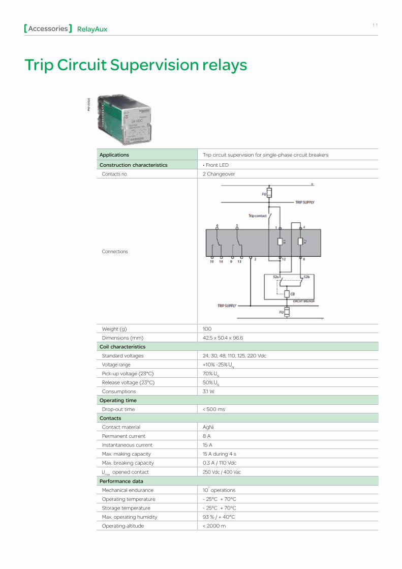
Applications Trip circuit supervision for single-phase circuit breakers
Construction characteristics • Front LED
Contacts no. 2 Changeover
Connections
Weight (g) 100
Dimensions (mm) 42.5 x 50.4 x 96.6
Coil characteristicsStandard voltages 24, 30, 48, 110, 125, 220 Vdc
Voltage range +10% -25%
Pick-up voltage (23°C) 70%
Release voltage (23°C) 50%
Consumptions 3.1 W
Operating timeDrop-out time < 500 ms
ContactsContact material AgNi
Permanent current 8 A
Instantaneous current 15 A
Max. making capacity 15 A during 4 s
Max. breaking capacity 0.3 A / 110 Vdc
opened contact 250 Vdc / 400 Vac
Performance dataMechanical endurance 10 operations
Operating temperature - 25°C + 70°C
Storage temperature - 25°C + 70°C
Max. operating humidity 93 % / + 40°C
Operating altitude < 2000 m
PM
1035
20
RelayAuxAccessories 12
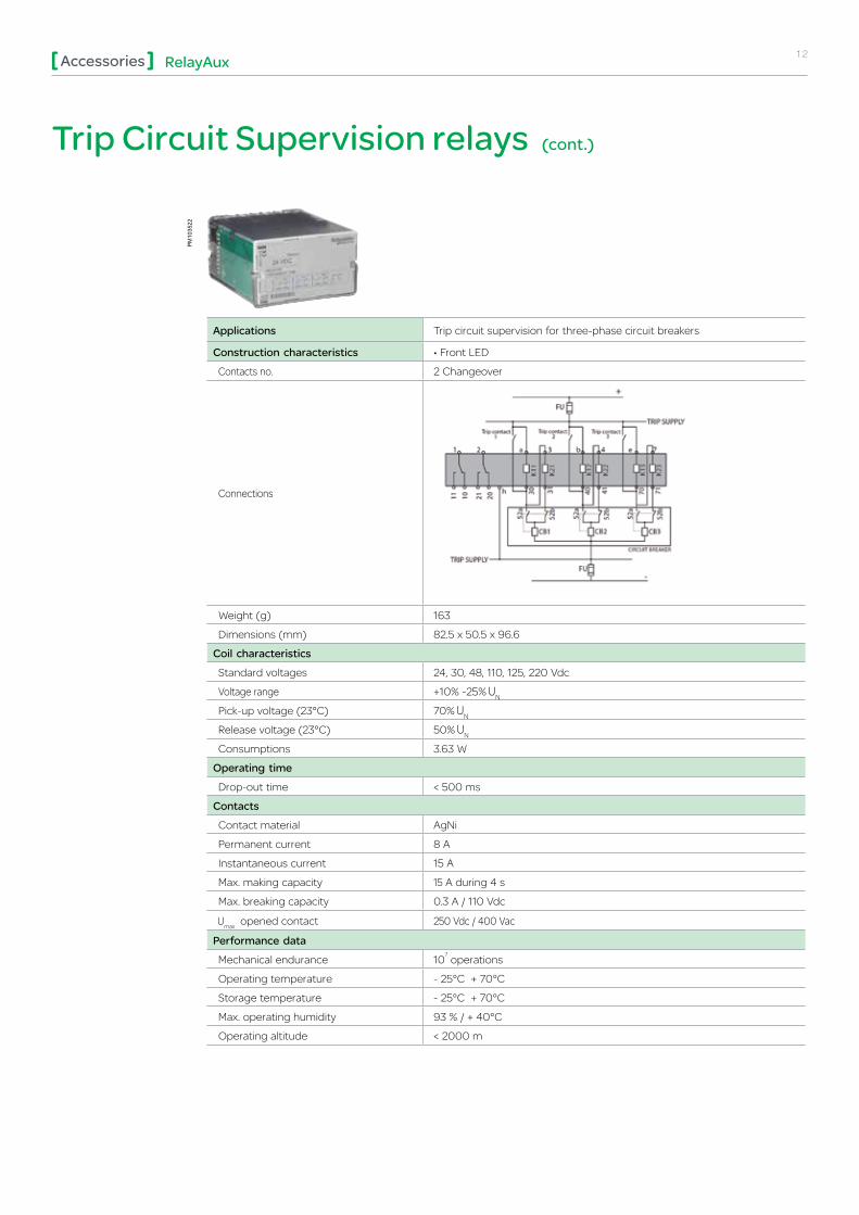
Trip Circuit Supervision relays (cont.)
Applications Trip circuit supervision for three-phase circuit breakers
Construction characteristics • Front LED
Contacts no. 2 Changeover
Connections
Weight (g) 163
Dimensions (mm) 82.5 x 50.5 x 96.6
Coil characteristicsStandard voltages 24, 30, 48, 110, 125, 220 Vdc
Voltage range +10% -25%
Pick-up voltage (23°C) 70%
Release voltage (23°C) 50%
Consumptions 3.63 W
Operating timeDrop-out time < 500 ms
ContactsContact material AgNi
Permanent current 8 A
Instantaneous current 15 A
Max. making capacity 15 A during 4 s
Max. breaking capacity 0.3 A / 110 Vdc
opened contact 250 Vdc / 400 Vac
Performance dataMechanical endurance 10 operations
Operating temperature - 25°C + 70°C
Storage temperature - 25°C + 70°C
Max. operating humidity 93 % / + 40°C
Operating altitude < 2000 m
PM
1035
22
13RelayAuxAccessories
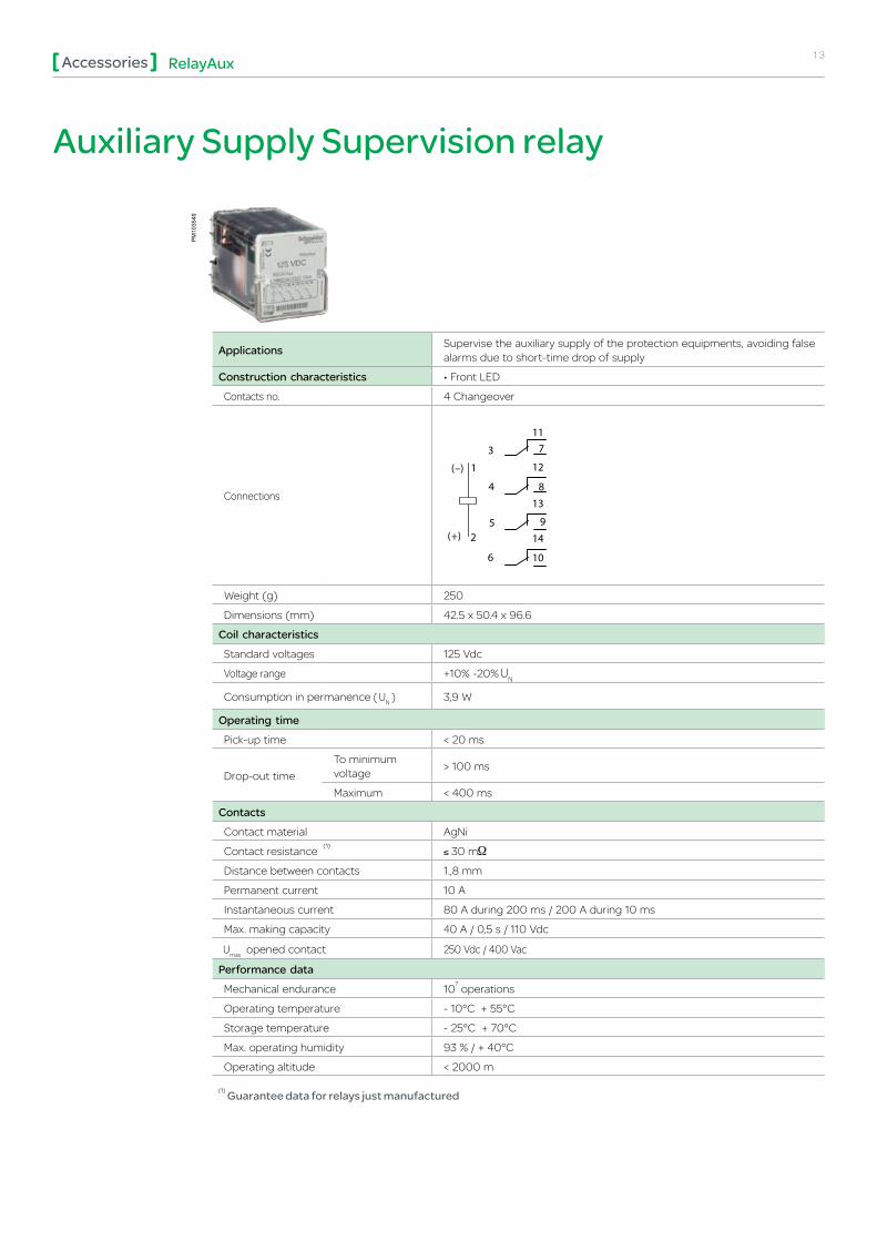
Auxiliary Supply Supervision relay
Applications Supervise the auxiliary supply of the protection equipments, avoiding false alarms due to short-time drop of supply
Construction characteristics • Front LED
Contacts no. 4 Changeover
Connections
711
12
13
9
14
10
5
3
1
2
( –)
4 8
6
( +)
Weight (g) 250
Dimensions (mm) 42.5 x 50.4 x 96.6
Coil characteristicsStandard voltages 125 Vdc
Voltage range +10% -20%
Consumption in permanence ( ) 3,9 W
Operating timePick-up time < 20 ms
Drop-out timeTo minimum voltage > 100 ms
Maximum < 400 ms
ContactsContact material AgNi
Contact resistance 30 m
Distance between contacts 1.,8 mm
Permanent current 10 A
Instantaneous current 80 A during 200 ms / 200 A during 10 ms
Max. making capacity 40 A / 0,5 s / 110 Vdc
opened contact 250 Vdc / 400 Vac
Performance dataMechanical endurance 10 operations
Operating temperature - 10°C + 55°C
Storage temperature - 25°C + 70°C
Max. operating humidity 93 % / + 40°C
Operating altitude < 2000 m
Guarantee data for relays just manufactured
PM
1035
49
RelayAuxAccessories 14
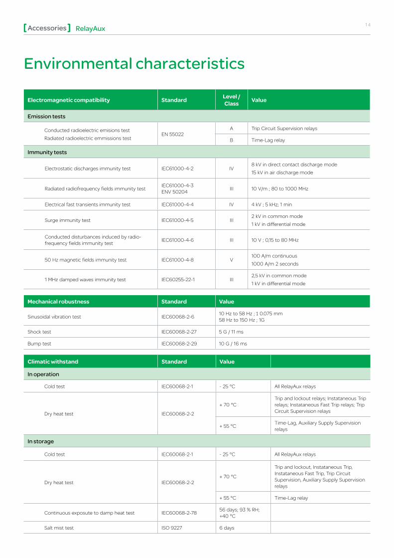
Environmental characteristics
Electromagnetic compatibility Standard Level / Class Value
Emission tests
Conducted radioelectric emisions testRadiated radioelectric emmissions test
EN 55022A Trip Circuit Supervision relays
B Time-Lag relay
Immunity tests
Electrostatic discharges immunity test IEC61000-4-2 IV8 kV in direct contact discharge mode 15 kV in air discharge mode
Radiated radiofrequency fields immunity test IEC61000-4-3 ENV 50204 III 10 V/m ; 80 to 1000 MHz
Electrical fast transients immunity test IEC61000-4-4 IV 4 kV ; 5 kHz; 1 min
Surge immunity test IEC61000-4-5 III2 kV in common mode 1 kV in differential mode
Conducted disturbances induced by radio-frequency fields immunity test IEC61000-4-6 III 10 V ; 0,15 to 80 MHz
50 Hz magnetic fields immunity test IEC61000-4-8 V100 A/m continuous 1000 A/m 2 seconds
1 MHz damped waves immunity test IEC60255-22-1 III2,5 kV in common mode 1 kV in differential mode
Climatic withstand Standard Value
In operation
Cold test IEC60068-2-1 - 25 °C All RelayAux relays
Dry heat test IEC60068-2-2
+ 70 °CTrip and lockout relays; Instataneous Trip relays; Instataneous Fast Trip relays; Trip Circuit Supervision relays
+ 55 °C Time-Lag, Auxiliary Supply Supervision relays
In storage
Cold test IEC60068-2-1 - 25 °C All RelayAux relays
Dry heat test IEC60068-2-2+ 70 °C
Trip and lockout, Instataneous Trip, Instataneous Fast Trip, Trip Circuit Supervision, Auxiliary Supply Supervision relays
+ 55 °C Time-Lag relay
Continuous exposute to damp heat test IEC60068-2-78 56 days; 93 % RH; +40 °C
Salt mist test ISO 9227 6 days
Mechanical robustness Standard Value
Sinusoidal vibration test IEC60068-2-6 10 Hz to 58 Hz ; ± 0.075 mm 58 Hz to 150 Hz ; 1G
Shock test IEC60068-2-27 5 G / 11 ms
Bump test IEC60068-2-29 10 G / 16 ms

15RelayAuxAccessories
Safety Standard Value
Electrical safety tests
Insulation resistance measurements IEC60255-5 > 100 M ; 500 Vdc
Dielectric strength test IEC60255-5 2 kV; 50 Hz; 1 min
Impulse voltage test IEC60255-5 5 kV; 1,2; 50 s
Enclosure safety test
Glow wire flammability index + 850 °C; 30 s
Degree of protection
IP 40 All RelayAux relays
IP20 Flush-mounting socket
IP10 Front connection socket
Certification
CE
Directives and Amendments
• 89/336/EEC Compliance with the European Commission Directive on EMC: - 92/31/EEC Amendment - 93/68/EEC Amendment
• 72/23/EEC Compliance with the European Commission Low voltage directive: - 93/68/EEC Amendment
UL File E322124
Environmental characteristics (cont.)

16RelayAuxAccessories
Order Codes and Dimensions Instantaneous trip relays & Instantaneous fast trip relays (4 changeover)
RelayAux Reference Sockets Reference
REL91200 to REL91205 / REL91220 to REL 91225 / REL91213 to REL 91215 / REL91233 to REL 91235 REL91350 REL91354 - REL91355
50,4
42,5
72
10,5
105
DIMENSIONS AND CUT-OUT
Sockets
RelayAux Type
Contacts no.
Pick up time Aux. Supply
Schneider Electric
RelayAux Reference
Front connect.
socket Screw
Reference (1) (2)
Flush mounting
socket Screw
Reference
Instantaneous trip relay
4 changeover < 20 ms
• Front LED• Mechanical contact position
indicator• Push test button
Low Burden
24 Vdc REL91200
REL91350 REL91354
30 Vdc REL91201
48 Vdc REL91202
110 Vdc REL91203
125 Vdc REL91204
220 Vdc REL91205
High Burden
110 Vdc REL91213
125 Vdc REL91214
220 Vdc REL91215
Instantaneous fast trip relay
4 changeover < 8 ms
• Diode in paralell with the coil• Front LED• Mechanical contact position
indicator• Trip flag
Low Burden
24 Vdc REL91220
REL91350 REL91355
30 Vdc REL91221
48 Vdc REL91222
110 Vdc REL91223
125 Vdc REL91224
220 Vdc REL91225
High Burden
110 Vdc REL91233
125 Vdc REL91234
220 Vdc REL91235
(1 ) DIN rail according to EN50022, DIN46277/3
(2) Minimum distance between sockets will depend on type of relay and sockets. Please request sockets User Manual for more detailed information
ORDER CODES PM
1035
26
PM
1035
24

17RelayAuxAccessories
Order Codes and Dimensions (cont.) Instantaneous fast trip relays (8 changeover)
Sockets
RelayAux Type
Contacts no.
Pick up time Aux. Supply
Schneider Electric
RelayAux Reference
Front connect.
socket Screw
Reference (1) (2)
Flush mounting
socket Screw
Reference
Instantaneous fast trip relay
8 changeover < 8 ms
• Diode in paralell with the coil• Front LED• Mechanical contact position
indicator• Trip flag
Low Burden
24 Vdc REL91240
REL91351 REL91356
30 Vdc REL91241
48 Vdc REL91242
110 Vdc REL91243
125 Vdc REL91244
220 Vdc REL91245
High Burden
110 Vdc REL91253
125 Vdc REL91254
220 Vdc REL91255
Instantaneous fast trip relay
8 changeover < 8 ms
• Diode in paralell with the coil• Front LED• Mechanical contact position
indicator• Trip flag• Push test button
High Burden 125 Vdc REL91259 REL91351 REL91356
(1 ) DIN rail according to EN50022, DIN46277/3
(2) Minimum distance between sockets will depend on type of relay and sockets. Please request sockets User Manual for more detailed information
ORDER CODES
RelayAux Reference Sockets Reference
REL91240 to REL91245 / REL91253 to REL91255 / REL91259 REL91351 REL91356
50,4
82,5
72
10,5
105
DIMENSIONS AND CUT-OUT
PM
1035
27
PM
1035
25
18RelayAuxAccessories
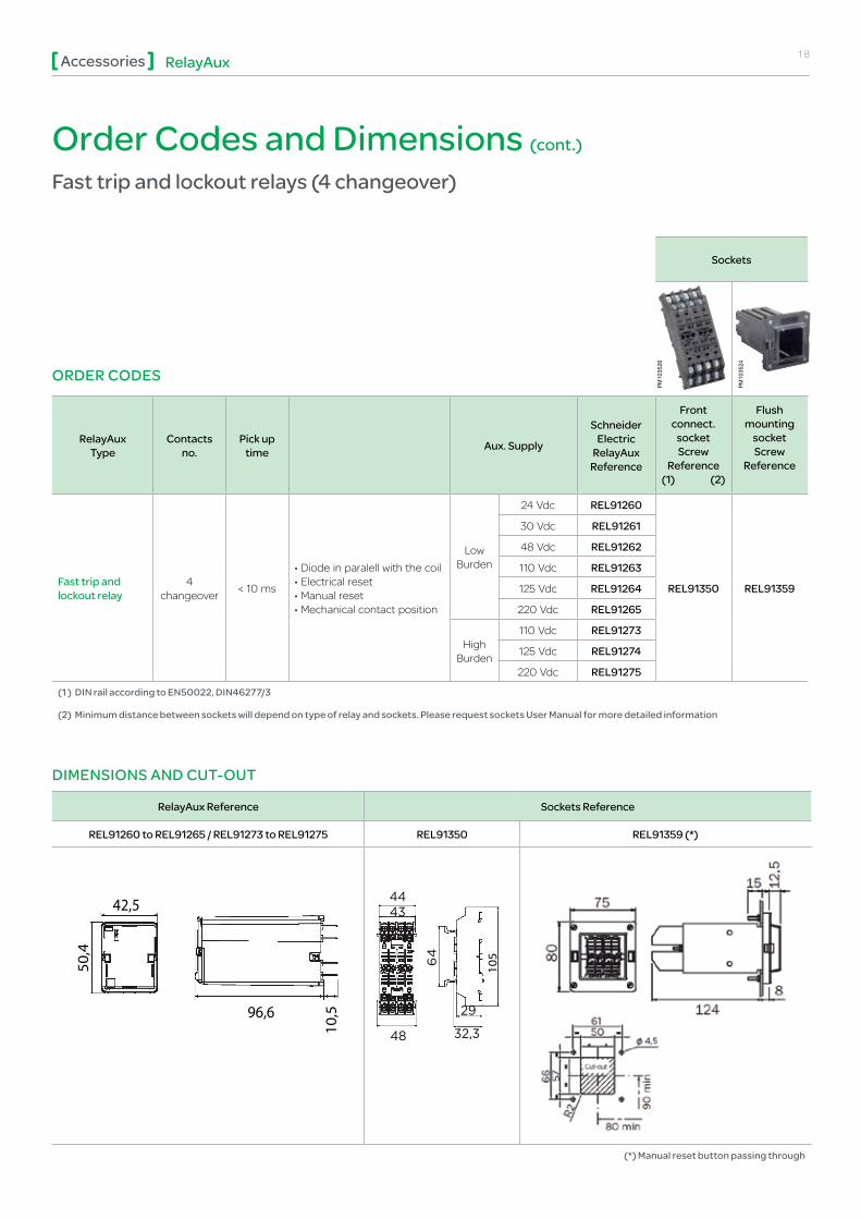
Order Codes and Dimensions (cont.) Fast trip and lockout relays (4 changeover)
RelayAux Reference Sockets Reference
REL91260 to REL91265 / REL91273 to REL91275 REL91350 REL91359 (*)
96,6
50,4
42,5
10,5
105
(*) Manual reset button passing through
DIMENSIONS AND CUT-OUT
Sockets
RelayAux Type
Contacts no.
Pick up time Aux. Supply
Schneider Electric
RelayAux Reference
Front connect.
socket Screw
Reference (1) (2)
Flush mounting
socket Screw
Reference
Fast trip and lockout relay
4 changeover < 10 ms
• Diode in paralell with the coil • Electrical reset • Manual reset• Mechanical contact position
Low Burden
24 Vdc REL91260
REL91350 REL91359
30 Vdc REL91261
48 Vdc REL91262
110 Vdc REL91263
125 Vdc REL91264
220 Vdc REL91265
High Burden
110 Vdc REL91273
125 Vdc REL91274
220 Vdc REL91275
(1 ) DIN rail according to EN50022, DIN46277/3
(2) Minimum distance between sockets will depend on type of relay and sockets. Please request sockets User Manual for more detailed information
ORDER CODES
PM
1035
26
PM
1035
24
SESA15659
Rectángulo

19RelayAuxAccessories
Order Codes and Dimensions (cont.) Fast trip and lockout relays (8 changeover)
RelayAux Reference Sockets Reference
REL91280 to REL91285 / REL91293 to REL91295 / REL91289 REL91351 REL91358 / REL91360 (*)
50,4
82,5
100,5
10,5
105
(*) Manual reset button passing through
DIMENSIONS AND CUT-OUT
Sockets
RelayAux Type
Contacts no.
Pick up time Aux. Supply
Schneider Electric
RelayAux Reference
Front connect.
socket Screw
Reference (1) (2)
Flush mounting
socket Screw
Reference
Fast trip and lockout relay
8 changeover < 10 ms
• Diode in paralell with the coil • Electrical reset • Manual reset• Mechanical contact position
Low Burden
24 Vdc REL91280
REL91351 REL91360
30 Vdc REL91281
48 Vdc REL91282
110 Vdc REL91283
125 Vdc REL91284
220 Vdc REL91285
High Burden
110 Vdc REL91293
125 Vdc REL91294
220 Vdc REL91295
Fast trip and lockout relay
8 changeover < 10 ms
• Diode in paralell with the coil • Electrical reset• Mechanical contact position
High Burden 125 Vdc REL91289 REL91351 REL91358
(1 ) DIN rail according to EN50022, DIN46277/3
(2) Minimum distance between sockets will depend on type of relay and sockets. Please request sockets User Manual for more detailed information
ORDER CODES PM
1035
27
PM
1035
25
ORDER CODES
Sockets
RelayAux Type
Contacts no.
Pick up time Aux. Supply
Schneider Electric
RelayAux Reference
Front connect.
socket Screw
Reference (1) (2)
Flush mounting
socket Screw
Reference
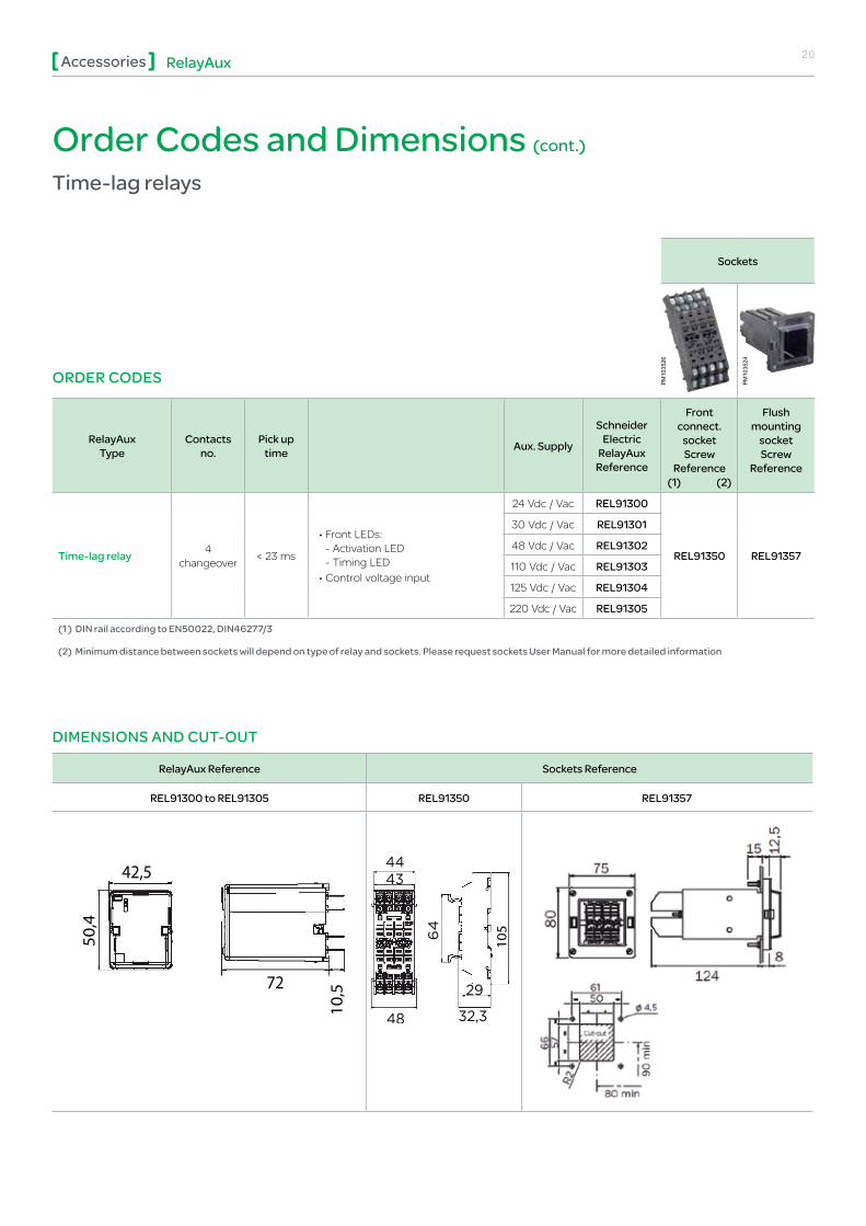
Time-lag relay 4 changeover < 23 ms
• Front LEDs: - Activation LED - Timing LED
• Control voltage input
24 Vdc / Vac REL91300
REL91350 REL91357
30 Vdc / Vac REL91301
48 Vdc / Vac REL91302
110 Vdc / Vac REL91303
125 Vdc / Vac REL91304
220 Vdc / Vac REL91305
(1 ) DIN rail according to EN50022, DIN46277/3
(2) Minimum distance between sockets will depend on type of relay and sockets. Please request sockets User Manual for more detailed information
20RelayAuxAccessories
Order Codes and Dimensions (cont.) Time-lag relays
RelayAux Reference Sockets Reference
REL91300 to REL91305 REL91350 REL91357
50,4
42,5
72
10,5
105
DIMENSIONS AND CUT-OUT
PM
1035
26
PM
1035
24
21RelayAuxAccessories
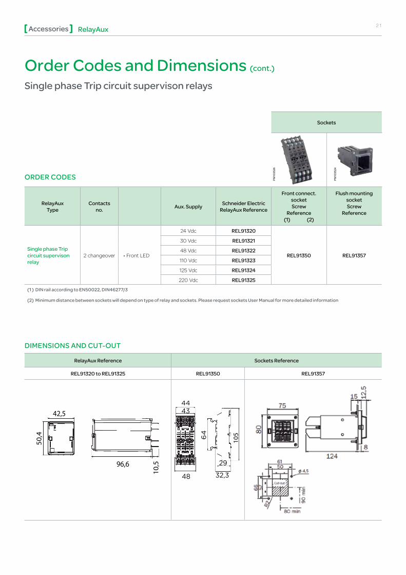
Order Codes and Dimensions (cont.) Single phase Trip circuit supervison relays
RelayAux Reference Sockets Reference
REL91320 to REL91325 REL91350 REL91357
96,6
50,4
42,5
10,5
105
DIMENSIONS AND CUT-OUT
ORDER CODES
Sockets
RelayAux Type
Contacts no. Aux. Supply Schneider Electric
RelayAux Reference
Front connect.socket Screw
Reference (1) (2)
Flush mounting socket Screw
Reference
Single phase Trip circuit supervison relay
2 changeover • Front LED
24 Vdc REL91320
REL91350 REL91357
30 Vdc REL91321
48 Vdc REL91322
110 Vdc REL91323
125 Vdc REL91324
220 Vdc REL91325
(1 ) DIN rail according to EN50022, DIN46277/3
(2) Minimum distance between sockets will depend on type of relay and sockets. Please request sockets User Manual for more detailed information
PM
1035
26
PM
1035
24

ORDER CODES
Sockets
RelayAux Type
Contacts no. Aux. Supply Schneider Electric
RelayAux Reference
Front connect.socket Screw
Reference (1) (2)
Flush mounting socket Screw
Reference
Three phase Trip circuit supervison relay
2 changeover • Front LED
24 Vdc REL91330
REL91351 REL91358
30 Vdc REL91331
48 Vdc REL91332
110 Vdc REL91333
125 Vdc REL91334
220 Vdc REL91335
(1 ) DIN rail according to EN50022, DIN46277/3
(2) Minimum distance between sockets will depend on type of relay and sockets. Please request sockets User Manual for more detailed information
22RelayAuxAccessories
Order Codes and Dimensions (cont.) Three phase Trip circuit supervison relays
RelayAux Reference Sockets Reference
REL91330 to REL91335 REL91351 REL91358
50,4
82,5
96,6
10,5
105
DIMENSIONS AND CUT-OUT
PM
1035
27
PM
1035
25

23RelayAuxAccessories
ORDER CODES
Sockets
RelayAux Type
Contacts no.
Pick up time Aux. Supply
Schneider Electric
RelayAux Reference
Front connect.
socket Screw
Reference (1) (2)
Flush mounting
socket Screw
Reference
Auxiliary Supply Supervision relay
4 changeover < 20 ms • Front LED 125 Vdc / Vac REL91344 REL91350 REL91357
(1 ) DIN rail according to EN50022, DIN46277/3
(2) Minimum distance between sockets will depend on type of relay and sockets. Please request sockets User Manual for more detailed information
Order Codes and Dimensions (cont.) Auxiliary Supply Supervision relays
RelayAux Reference Sockets Reference
REL91344 REL91350 REL91357
50,4
42,5
72
10,5
105
DIMENSIONS AND CUT-OUTP
M10
3526
PM
1035
24

24RelayAuxAccessories
Breaking capacity & Electrical enduranceThe breaking capacity is a critical parameter on the design and the applications of the relays. Its mechanical life could be considerably reduced, depending on the value of the load (especially with heavy duty loads), the number of operations and the environmental conditions in which the relay is operating.
In any configuration, RelayAux relays have a high breaking capacity values. These limits are showed in the following table, in terms of power and current values.
In all the cases, these relays guarantee a right performance during 50,000 operations.
RelayAux relays are power relays designed especially to have a high breaking capacity. Thus, there are applications where the loads are so high that it is necessary to even increase the breaking capacity, keeping the reliability of the contacts of the auxiliary relays.
The breaking capacity can be increased by connecting serial contacts. The breaking capacity is increased considerably, guaranteeing the right performance during a high number of operations. See curves for two contacts.
High / Low Burden relays(Instantaneous Trip relay and Trip and lockout relays)
Low burden configuration tripping relays are recommended when the initiating contact is placed close to the tripping relay.
However, and in order to avoid unwanted trip relay operation due to pickup or transients, particularly if the relay operating coil is connected to extensive wiring, RelayAux tripping relays could be used with a high burden configuration, complying with ESI 48-4 international standard, as EB2 class relays.
These EB2 class relays are suitable for use in high security circuit breaker tripping circuits, increasing their immunity to capacitance discharge currents.
For relays with rated voltage up to and including the 125 V, the relays will withstand, without operating, a discharge into their operate circuits of a 10 capacitor charged to 120% of the higher rated voltage for the relay.
For relays with rated voltage of 220 V, the relays will withstand, without operating, a discharge into their operate circuits of a 10 capacitor charged to 100% of the higher rated voltage for the relay, i.e. 242 V.
Specifications:• ESI 48-4 EB1: 1983 Low Burden
• ESI 48-4 EB2: 1983 High Burden

25RelayAuxAccessories
24 Vdc voltageDifferent loads configurations
L/R= 0 ms L/R= 40 msResistive load Highly inductive load
0 5 10
10 7
10 6
10 5
10 4
No.
ope
ratio
ns
No.
ope
ratio
ns
Current Current
15 20 25
10 7
10 6
10 5
10 4
2186420 1 0
Instantaneous Fast Trip relays (REL 91220 to REL 91225 and REL 91240 to REL 91245)Time-Lag relays (REL 91300 to REL 91305)
Instantaneous Trip relays (REL 91200 to REL 91205)Fast Trip and Lockout relays (REL 91260 to REL 91265 and REL 91280 to REL 91285)
0 ms 20 ms 40 ms
Vdc RelayAux type P(W) I(A) P(W) I(A) P(W) I(A)
24
1 contact Instantaneous Trip relays (REL 91200 to REL 91205) Fast Trip and Lockout relays (REL 91260 to REL 91265 and REL 91280 to REL 91285)
500 20.83 370 15.42 250 10.42
1 contact Instantaneous Fast Trip relays (REL 91220 to REL 91225 and REL 91240 to REL 91245) Time-Lag relays (REL 91300 to REL 91305)
450 18.75 300 12.50 210 8.75

26RelayAuxAccessories
110 Vdc voltageDifferent loads configurations
0 ms 20 ms 40 ms
Vdc RelayAux type P(W) I(A) P(W) I(A) P(W) I(A)
110
1 contact Instantaneous Trip relays (REL 91200 to REL 91205) Fast Trip and Lockout relays (REL 91260 to REL 91265 and REL 91280 to REL 91285)
170 1.55 140 1.27 90 0.82
1 contact Instantaneous Fast Trip relays (REL 91220 to REL 91225 and REL 91240 to REL 91245) Time-Lag relays (REL 91300 to REL 91305)
125 1.14 100 0.91 65 0.59
2 contacts Instantaneous Trip relays (REL 91200 to REL 91205) Fast Trip and Lockout relays (REL 91260 to REL 91265 and REL 91280 to REL 91285)
1360 12.36 1106 10.05 730 6.63
2 contacts Instantaneous Fast Trip relays (REL 91220 to REL 91225 and REL 91240 to REL 91245) Time-Lag relays (REL 91300 to REL 91305)
874 7.95 742 6.74 482 4.38
No.
ope
ratio
ns
Current
No.
ope
ratio
ns
Current
10 7
10 6
10 5
10 4
10 7
10 6
10 5
10 4
0150 721 5098643 721 643
L/R= 0 ms L/R= 40 msResistive load Highly inductive load
Instantaneous Fast Trip relays (REL 91220 to REL 91225 and REL 91240 to REL 91245)Time-Lag relays (REL 91300 to REL 91305)
Instantaneous Trip relays (REL 91200 to REL 91205)Fast Trip and Lockout relays (REL 91260 to REL 91265 and REL 91280 to REL 91285)
1 contact2 contacts
1 contact2 contacts
27RelayAuxAccessories
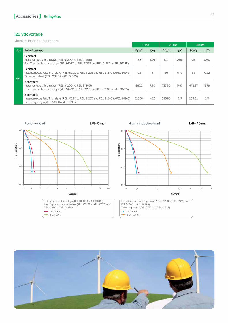
125 Vdc voltageDifferent loads configurations
0 ms 20 ms 40 ms
Vdc RelayAux type P(W) I(A) P(W) I(A) P(W) I(A)
125
1 contact Instantaneous Trip relays (REL 91200 to REL 91205) Fast Trip and Lockout relays (REL 91260 to REL 91265 and REL 91280 to REL 91285)
158 1.26 120 0.96 75 0.60
1 contact Instantaneous Fast Trip relays (REL 91220 to REL 91225 and REL 91240 to REL 91245) Time-Lag relays (REL 91300 to REL 91305)
125 1 96 0.77 65 0.52
2 contacts Instantaneous Trip relays (REL 91200 to REL 91205) Fast Trip and Lockout relays (REL 91260 to REL 91265 and REL 91280 to REL 91285)
987.5 7.90 733.80 5.87 472.97 3.78
2 contacts Instantaneous Fast Trip relays (REL 91220 to REL 91225 and REL 91240 to REL 91245) Time-Lag relays (REL 91300 to REL 91305)
528.54 4.23 395.98 3.17 263.82 2.11
No.
ope
ratio
ns
Current
No.
ope
ratio
ns
Current
10 7
10 6
10 5
10 4
0 0,5 1 5,1 2 5,2 3 45,3
10 7
10 6
10 5
10 4
0150 721 98643
L/R= 0 ms L/R= 40 msResistive load Highly inductive load
Instantaneous Fast Trip relays (REL 91220 to REL 91225 and REL 91240 to REL 91245)Time-Lag relays (REL 91300 to REL 91305)
Instantaneous Trip relays (REL 91200 to REL 91205)Fast Trip and Lockout relays (REL 91260 to REL 91265 and REL 91280 to REL 91285)
1 contact2 contacts
1 contact2 contacts
RelayAuxAccessories 28
02-2014 © 2
014
Sch
neid
er E
lect
ric In
dust
ries
SA
S -
All
right
s re
serv
ed
As standards, specifications and designs change from time to time, please ask for confirmation of the information given in this publication.
Design: Schneider Electric Industries SAS - SonovisionPhotos: Schneider Electric Industries SAS Printed: Altavia Connexion - Made in France
NRJED113433EN
This document has been printed on recycled paper.
Schneider Electric Industries SAS
35, rue Joseph Monier CS 30323 F - 92506 Rueil Malmaison Cedex (France)Tel.: +33 (0) 1 41 29 70 00RCS Nanterre 954 503 439 Capital social 896 313 776 €www.schneider-electric.com
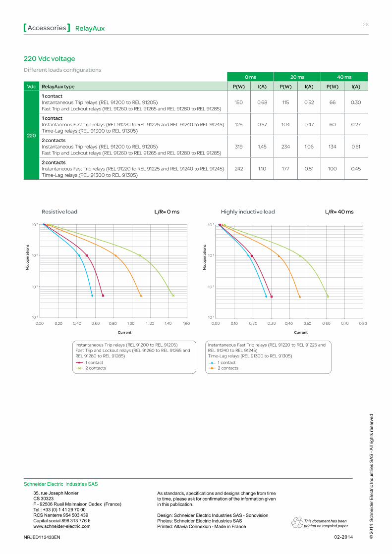
220 Vdc voltageDifferent loads configurations
0 ms 20 ms 40 ms
Vdc RelayAux type P(W) I(A) P(W) I(A) P(W) I(A)
220
1 contact Instantaneous Trip relays (REL 91200 to REL 91205) Fast Trip and Lockout relays (REL 91260 to REL 91265 and REL 91280 to REL 91285)
150 0.68 115 0.52 66 0.30
1 contact Instantaneous Fast Trip relays (REL 91220 to REL 91225 and REL 91240 to REL 91245) Time-Lag relays (REL 91300 to REL 91305)
125 0.57 104 0.47 60 0.27
2 contacts Instantaneous Trip relays (REL 91200 to REL 91205) Fast Trip and Lockout relays (REL 91260 to REL 91265 and REL 91280 to REL 91285)
319 1.45 234 1.06 134 0.61
2 contacts Instantaneous Fast Trip relays (REL 91220 to REL 91225 and REL 91240 to REL 91245) Time-Lag relays (REL 91300 to REL 91305)
242 1.10 177 0.81 100 0.45
No.
ope
ratio
ns
Current
No.
ope
ratio
ns
Current
10 7
10 6
10 5
10 4
10 7
10 6
10 5
10 4
0,00 0,20 106,004,0 ,20 1,40 1,600,80 1,00 0,00 0,10 003,002,0 ,60 0,70 0,800,40 0,50
L/R= 0 ms L/R= 40 msResistive load Highly inductive load
Instantaneous Fast Trip relays (REL 91220 to REL 91225 and REL 91240 to REL 91245)Time-Lag relays (REL 91300 to REL 91305)
Instantaneous Trip relays (REL 91200 to REL 91205)Fast Trip and Lockout relays (REL 91260 to REL 91265 and REL 91280 to REL 91285)
1 contact2 contacts
1 contact2 contacts