
REHABILITATING WATER FILTER SYSTEMS WITH … · Rehabilitating Water Filter Systems with Potential...
10
199 REHABILITATING WATER FILTER SYSTEMS WITH POTENTIAL CUBA APPLICATIONS Thomas Getting, John Geibel, Mainor Vega, Robert Wiley III, Hernán Cortés A. The nation of Cuba derives its drinking water from both surface water and groundwater sources. Usually treatment for groundwater sources is chlorination with no further treatment. Cueto, et al estimate there are 59 surface water treatment plants that use a com- bination of American, European, Soviet and Cuban designs. Many use conventional treatment processes which consist of chemical addition, flash mixing, co- agulation, clarification, filtration, and disinfection. Some may use direct filtration, which would consist of chemical addition, flash mixing, coagulation, fil- tration and disinfection. This paper will look at the rehabilitation of existing gravity, granular media fil- tration systems using the dual parallel lateral underd- rain design along with updating other aspects of gravity filtration systems that could be used in Cuba to upgrade its water treatment systems. The paper concludes with illustrative costs based on other gravi- ty filter rehabilitation that has been recently done in the Latin American region. GRAVITY FILTRATION Gravity filtration in water treatment is the passage of water through a porous, granular medium for the physical removal of suspended solids and turbidity. If conditions are proper, biological growth within the medium can remove other contaminants. The earli- est written records of water treatment, dating from about 4000 BC, mention filtration of water through charcoal or sand and gravel. Although a number of modifications have been in the manner of applica- tion, filtration remains one of the fundamental pro- cess technologies associated with water treatment. Granular filter media (effective sizes ranging from 0.5-1.5 mm) will generally remove particles that are larger than 7-10% of the smallest media grains. Most water treatment applications try to remove color and all solids greater than 10-20 microns. Smaller parti- cles are removed using chemicals to destabilize colloi- dal dispersions and enhance the growth or coagula- tion of particles into a size that can be removed. For additional biological treatment other chemistry can be added as a food source for the biology. In gravity filters, the conditioned raw water is intro- duced into the top of a basin, flows down through the selected media bed, and is collected by the un- derdrain system as shown in Figure 1. The driving force through the system is the distance from the wa- ter level over the filter to the first air break which is usually into a clearwell or control weir. As solids are accumulated and/or biology grows in the filter me- dia, the headloss or force required to maintain flow increases. A point is reached where either the flow cannot be maintained or solids are driven through the filter. An upward flow of water or a combination of air and water (called a backwash) is used to scour and fluidize the media thereby removing the accu- mulated particles with some of the biology and re- storing the driving force. The effectiveness of a back- wash operation is measured by the resulting cleanliness of the media and the associated costs of power and water required to perform the backwash. The current best practice backwash is to begin with an air scour to agitate the media surface, followed by an air scour with low rate water backwash in the “col-
Transcript of REHABILITATING WATER FILTER SYSTEMS WITH … · Rehabilitating Water Filter Systems with Potential...

199
REHABILITATING WATER FILTER SYSTEMS WITH POTENTIAL CUBA APPLICATIONS
Thomas Getting, John Geibel, Mainor Vega, Robert Wiley III, Hernán Cortés A.
The nation of Cuba derives its drinking water from both surface water and groundwater sources. Usually treatment for groundwater sources is chlorination with no further treatment. Cueto, et al estimate there are 59 surface water treatment plants that use a com-bination of American, European, Soviet and Cuban designs. Many use conventional treatment processes which consist of chemical addition, flash mixing, co-agulation, clarification, filtration, and disinfection. Some may use direct filtration, which would consist of chemical addition, flash mixing, coagulation, fil-tration and disinfection. This paper will look at the rehabilitation of existing gravity, granular media fil-tration systems using the dual parallel lateral underd-rain design along with updating other aspects of gravity filtration systems that could be used in Cuba to upgrade its water treatment systems. The paper concludes with illustrative costs based on other gravi-ty filter rehabilitation that has been recently done in the Latin American region.
GRAVITY FILTRATIONGravity filtration in water treatment is the passage of water through a porous, granular medium for the physical removal of suspended solids and turbidity. If conditions are proper, biological growth within the medium can remove other contaminants. The earli-est written records of water treatment, dating from about 4000 BC, mention filtration of water through charcoal or sand and gravel. Although a number of modifications have been in the manner of applica-tion, filtration remains one of the fundamental pro-cess technologies associated with water treatment.
Granular filter media (effective sizes ranging from 0.5-1.5 mm) will generally remove particles that are larger than 7-10% of the smallest media grains. Most water treatment applications try to remove color and all solids greater than 10-20 microns. Smaller parti-cles are removed using chemicals to destabilize colloi-dal dispersions and enhance the growth or coagula-tion of particles into a size that can be removed. For additional biological treatment other chemistry can be added as a food source for the biology.
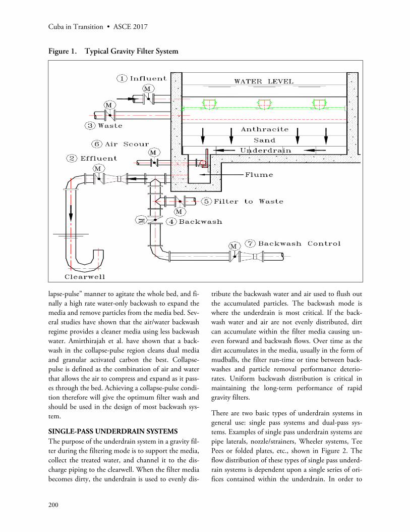
In gravity filters, the conditioned raw water is intro-duced into the top of a basin, flows down through the selected media bed, and is collected by the un-derdrain system as shown in Figure 1. The driving force through the system is the distance from the wa-ter level over the filter to the first air break which is usually into a clearwell or control weir. As solids are accumulated and/or biology grows in the filter me-dia, the headloss or force required to maintain flow increases. A point is reached where either the flow cannot be maintained or solids are driven through the filter. An upward flow of water or a combination of air and water (called a backwash) is used to scour and fluidize the media thereby removing the accu-mulated particles with some of the biology and re-storing the driving force. The effectiveness of a back-wash operation is measured by the resulting cleanliness of the media and the associated costs of power and water required to perform the backwash.
The current best practice backwash is to begin with an air scour to agitate the media surface, followed by an air scour with low rate water backwash in the “col-
Cuba in Transition • ASCE 2017
200
lapse-pulse” manner to agitate the whole bed, and fi-nally a high rate water-only backwash to expand the media and remove particles from the media bed. Sev-eral studies have shown that the air/water backwash regime provides a cleaner media using less backwash water. Amirthirajah et al. have shown that a back-wash in the collapse-pulse region cleans dual media and granular activated carbon the best. Collapse-pulse is defined as the combination of air and water that allows the air to compress and expand as it pass-es through the bed. Achieving a collapse-pulse condi-tion therefore will give the optimum filter wash and should be used in the design of most backwash sys-tem.
SINGLE-PASS UNDERDRAIN SYSTEMSThe purpose of the underdrain system in a gravity fil-ter during the filtering mode is to support the media, collect the treated water, and channel it to the dis-charge piping to the clearwell. When the filter media becomes dirty, the underdrain is used to evenly dis-
tribute the backwash water and air used to flush out the accumulated particles. The backwash mode is where the underdrain is most critical. If the back-wash water and air are not evenly distributed, dirt can accumulate within the filter media causing un-even forward and backwash flows. Over time as the dirt accumulates in the media, usually in the form of mudballs, the filter run-time or time between back-washes and particle removal performance deterio-rates. Uniform backwash distribution is critical in maintaining the long-term performance of rapid gravity filters.
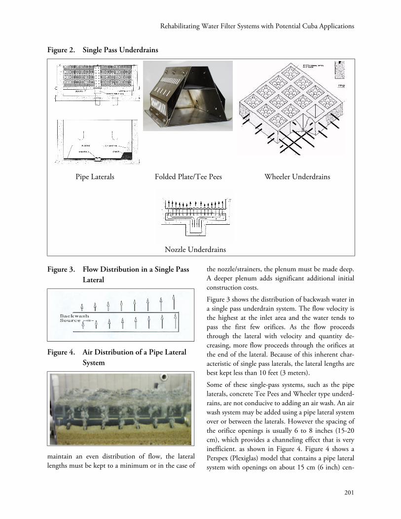
There are two basic types of underdrain systems in general use: single pass systems and dual-pass sys-tems. Examples of single pass underdrain systems are pipe laterals, nozzle/strainers, Wheeler systems, Tee Pees or folded plates, etc., shown in Figure 2. The flow distribution of these types of single pass underd-rain systems is dependent upon a single series of ori-fices contained within the underdrain. In order to
Figure 1. Typical Gravity Filter System
Rehabilitating Water Filter Systems with Potential Cuba Applications
201
maintain an even distribution of flow, the lateral lengths must be kept to a minimum or in the case of
the nozzle/strainers, the plenum must be made deep. A deeper plenum adds significant additional initial construction costs.
Figure 3 shows the distribution of backwash water in a single pass underdrain system. The flow velocity is the highest at the inlet area and the water tends to pass the first few orifices. As the flow proceeds through the lateral with velocity and quantity de-creasing, more flow proceeds through the orifices at the end of the lateral. Because of this inherent char-acteristic of single pass laterals, the lateral lengths are best kept less than 10 feet (3 meters).
Some of these single-pass systems, such as the pipe laterals, concrete Tee Pees and Wheeler type underd-rains, are not conducive to adding an air wash. An air wash system may be added using a pipe lateral system over or between the laterals. However the spacing of the orifice openings is usually 6 to 8 inches (15-20 cm), which provides a channeling effect that is very inefficient. as shown in Figure 4. Figure 4 shows a Perspex (Plexiglas) model that contains a pipe lateral system with openings on about 15 cm (6 inch) cen-
Figure 2. Single Pass Underdrains
Pipe Laterals Folded Plate/Tee Pees Wheeler Underdrains
Nozzle Underdrains
Figure 3. Flow Distribution in a Single Pass Lateral
Figure 4. Air Distribution of a Pipe Lateral System

Cuba in Transition • ASCE 2017
202
ters. Not only is the channeling evident but this air lateral system is located above the support gravel. Be-sides not cleaning the gravel, the underdrain does not benefit from air scour cleaning.
Nozzle/strainer systems can be retrofitted with air scour. Figure 5 shows a Perspex (Plexiglas) model with nozzles in the air backwash mode. The nozzles are at 15 cm (6 inch) x 20 cm (8 inch) centers. Note the channeling effect of the air as it rises out of the top of the nozzle. The area immediately between the
nozzles and above for about 15 cm (6 inches) does not benefit from the air scour. When inspecting this type of underdrain from the top it appears that there is uniform coverage of air. However viewed from the side, the channeling is evident. This channeling pro-vides an area for the deposition of solids. During re-placement of these types of underdrains, it has been observed that the filter walls are stained with dirt de-posits as shown in Figure 6. The dead zone is evi-dence that air and water are not cleaning the media at the lower levels.
THE DUAL-PARALLEL LATERAL
The dual parallel lateral was developed to solve the flow distribution problems of other systems. As shown in Figure 7, it consists of a primary lateral and two secondary compensating laterals which are paral-lel to each other. Control orifices open from the pri-mary lateral directly into the secondary laterals. Backwash water is introduced into and flows through the primary lateral, rises and discharges from the con-trol orifices into the secondary compensating lateral. Any unbalanced flow from the primary lateral creates an opposing flow, forming a directly compensating velocity pressure gradient which puts the secondary lateral into a uniform hydraulic pressure condition throughout its length as shown in Figure 8. This uni-form pressure services the top deck dispersion orifices that discharge from the compensating lateral into the filter box.
Hydraulics dictates that, neglecting friction, the amount of water that will flow from a lateral through a particular orifice is a function of the orifice coeffi-cient and the hydraulic gradient in the lateral at the entry to the orifice. In a lateral having equal sized and shape orifices along its length, the orifice furthest form the point of admittance will deliver the most water. These discharge variances exist in the primary lateral of the dual parallel lateral underdrain, as in any single-pass lateral system as shown in Figure 3. The function of the secondary/compensating laterals is to provide a compensation or balance to these vari-ances. This system provides an automatic equaliza-tion of pressure prior to discharging the backwash water from the underdrain, resulting in complete uniform discharge along the entire length of the lat-
Figure 5. Nozzles During Air Scour
Figure 6. Dead Zone Effect from Nozzles

Rehabilitating Water Filter Systems with Potential Cuba Applications
203
eral. Dual parallel laterals can be sized up to 15 m (50 feet) in length with a backwash lateral mal-distri-bution of less than ±2%. Mal-distribution is the per-cent difference in flow from one part of a lateral or underdrain system to another. Usually the highest and lowest points of flow or pressure are used to de-termine mal-distribution.
An additional benefit of the dual-parallel lateral is its unique ability to meter and uniformly distribute air. Widely spaced nozzles, such as those used in single pass systems, release large volumes of air creating dis-ruptive “explosions” propelling media to the surface and providing zones of low or no turbulence. The triangular shape of the primary lateral collects incom-ing air uniformly along its length. Small dispersion orifices as shown in Figure 9, then distribute and me-ter the air uniformly to the top deck discharge orific-es. The top deck orifices are closely spaced at 5 cm (2 inch) centers to provide a more uniform coverage of the filter floor. A baffle in the bell end of the second-
ary laterals ensures that the air and water that are me-tered into each 1.2 m (4 feet) section are discharged from that section. Without the baffle, the backwash water tends to push the air up and down the lateral causing pulsations.
The latest developments in the dual parallel lateral underdrain design are the arched primary conduit, dual water recovery channels, water baffles in the sec-ondary and a grout pocket on the bottom of the un-derdrain. The arched primary allows more air and water to flow through the underdrain which in turn allows for up to 40% longer lateral lengths than the previous low profile underdrain. This means that the low profile underdrain can be used in larger filters. The dual water recovery channels allow more uni-form air distribution through the top deck orifices during air scour. The water baffles on the arch wall
Figure 7. Dual Parallel Lateral Underdrain
Figure 8. Flow Distribution in a Dual Pass Lateral Showing the Effect of the Compensating lateral
Figure 9. Air Dispersion in the Dual Parallel Lateral Underdrain

Cuba in Transition • ASCE 2017
204
reduce secondary velocities and provide extra crush strength. The grout pocket on the bottom of the un-derdrain provides up to 3 times the resistance to in-ternal uplift pressure than the older underdrain de-signs. Sometimes pressure transients are caused in the backwash system. The grout pocket provides addi-tional insurance against these unexpected pressure transients. All of these new developments add up to the latest in gravity, granular filter underdrain design.
INSTALLATION OF THE DUAL PARALLEL LATERAL
The installation of the dual parallel lateral is very simple. The filter compartment is constructed like a box with a rough-finished, plain flat floor. The de-sign does not require any special sub-structure, such as supporting piers or beams, nor does it require add-ed filter depth for a plenum or false floor. The 1.2 m (4’) dual parallel lateral blocks are set in a base grout directly on the flat filter floor with minimum anchor-age required.
The dual parallel lateral blocks are placed end-to-end in rows so the laterals are continuous through the length of each row. Rows of blocks are placed on ± 30.5 cm (12 inch) centers across the width of filter. The space between the rows is filled with grout, lock-ing the blocks together and making a flat and level tile floor that is an integral part of the filter box.
Figure 1 shows the typical installation of the dual parallel lateral in a filter with a front flume. The backwash water enters the flume, travels into the dual parallel laterals, is dispersed up into the media, and finally is collected by fiberglass washwater troughs. Note the air header piping in the flume that uses “j-risers” to distribute the air to each dual parallel later-al. The air riser “j” shape is used to flush any water that accumulates in the bottom of the air header pip-ing as the air fills the header.
MEDIA EFFECTS ON BACKWASH DISTRIBUTION
Underdrain systems can be designed to produce low mal-distribution within the filter box and in some cases with low overall headloss. However, the instal-lation of media adds another factor to be considered.
Flow distribution is headloss driven. A headloss dif-ferential is required for one component to control another. Some underdrain manufacturers claim they can produce good mal-distribution with low head-loss. If piping and distribution elements are sized properly, low mal-distribution can be achieved with a bare underdrain. However, if the media headloss is higher than that of the underdrain in the backwash mode, mal-distribution can occur. When the media is dirty, an even higher pressure is required to loosen and fluidize the media bed.
As the backwash rate is increased, a headloss spike oc-curs at the point of incipient media fluidization due to compaction and solids accumulation. During this period, the media will have significantly higher head-loss than the underdrain as shown in Figure 10. The distribution provided by the underdrain may not be adequate to clean the bed uniformly. As the bed goes into fluidization, localized regions become zones of lower headloss accentuating mal-distribution beyond that expected for the underdrain. The media will then be controlling backwash distribution, not the underdrain. The media can then contribute to the mal-distribution in the filter.
Figure 10. Media Headloss Controls Backwash Flow until the Underdrain Headloss Exceeds the Media Headloss

Rehabilitating Water Filter Systems with Potential Cuba Applications
205
Two important conclusions can be drawn: the un-derdrain headloss should be higher than that of the media at the design backwash flow rate and air scour should be used to help prevent the build-up of solids in the media.
REHABILITATING EXISTING UNDERDRAINS USING THE DUAL-PARALLEL LATERALWhen rehabilitating an existing filter system, such as those that exist in Cuba, many factors must be con-sidered. These factors include an adequate backwash flow based on the existing backwash system, configu-ration of the backwash flume, depth and shape of the filter box, and characteristics of the proposed media. The backwash flow rate is dependent on the type of media to be used. If using a dual media, the back-wash flow rate should be adequate to fluidize the large particles of the media, usually the anthracite de-pending on the specific gravity and particle sizes used. During an air scour, the sand and anthracite are mixed together. Adequate fluidization is required to flush the accumulated solids from the filter as well as separate the sand from the anthracite. The usual design backwash flow rate for a standard dual media is 49 m/h (20 gpm/sf) at 21° C (70° F).
The configuration of the backwash flume is very im-portant as it is one of the major contributors of mal-distribution in a filter along with the underdrain lat-eral type and the media as discussed before. If a back-wash flume does not exist, one needs to be construct-ed on the floor of the filter. Figure 11 shows the progression of removing the floor of a nozzle/strainer
or Wheeler underdrain system and filling between the dwarf walls to form a flume. The dual parallel lat-eral is placed perpendicular to the flume and the backwash water is introduced into the bottom of the underdrain through cut-outs in the block. Air can also be introduced to the bottom of the underdrain using j-risers similar to the ones shown in Figure 1. The flume is designed so that the equalized flow ve-locity is 2 km/h (2 fps) or less and the backwash en-try pipe velocity is 4 km/h (4 fps) or less. If the en-trance velocity is too great, baffling is provided to dissipate the entrance energy and allow the flow to equally enter all of the laterals.
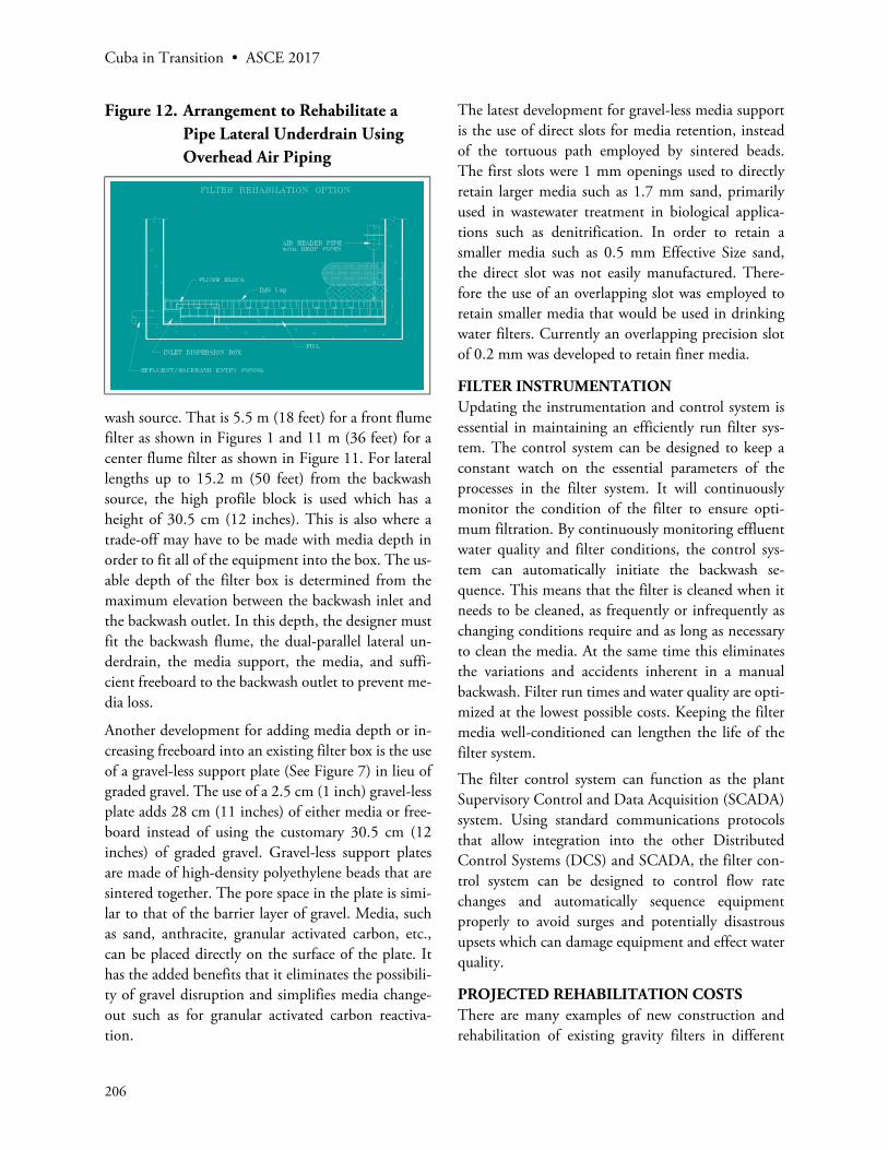
Figure 12 shows the arrangement used to rehabilitate a pipe lateral type of underdrain. A layer of fill grout is placed on the floor and the flume block is cut-out to add additional flume area. In this case the flume was not large enough to accommodate the air header piping so the air was introduced overhead with drop pipes to the primary lateral.
The configuration of the filter box in a filter rehabili-tation will influence many decisions. First it will de-termine the length of the dual parallel laterals. The location of the backwash entry will determine the lo-cation of the flume such as a front flume or a center flume or no flume and possibly the size of the flume. The length of the lateral will determine the type of block. Low profile dual-parallel lateral blocks with a height of 20 cm (8 inch) have been developed for shallow depth filter boxes (See Figure 7). But for an air/water backwash, the lateral length of the low pro-file block is limited to 5.5 m (18 feet) from the back-
Figure 11. Typical Rehabilitation of a Single Pass, Plenum Type Filter
Cuba in Transition • ASCE 2017
206
wash source. That is 5.5 m (18 feet) for a front flume filter as shown in Figures 1 and 11 m (36 feet) for a center flume filter as shown in Figure 11. For lateral lengths up to 15.2 m (50 feet) from the backwash source, the high profile block is used which has a height of 30.5 cm (12 inches). This is also where a trade-off may have to be made with media depth in order to fit all of the equipment into the box. The us-able depth of the filter box is determined from the maximum elevation between the backwash inlet and the backwash outlet. In this depth, the designer must fit the backwash flume, the dual-parallel lateral un-derdrain, the media support, the media, and suffi-cient freeboard to the backwash outlet to prevent me-dia loss.
Another development for adding media depth or in-creasing freeboard into an existing filter box is the use of a gravel-less support plate (See Figure 7) in lieu of graded gravel. The use of a 2.5 cm (1 inch) gravel-less plate adds 28 cm (11 inches) of either media or free-board instead of using the customary 30.5 cm (12 inches) of graded gravel. Gravel-less support plates are made of high-density polyethylene beads that are sintered together. The pore space in the plate is simi-lar to that of the barrier layer of gravel. Media, such as sand, anthracite, granular activated carbon, etc., can be placed directly on the surface of the plate. It has the added benefits that it eliminates the possibili-ty of gravel disruption and simplifies media change-out such as for granular activated carbon reactiva-tion.
The latest development for gravel-less media support is the use of direct slots for media retention, instead of the tortuous path employed by sintered beads. The first slots were 1 mm openings used to directly retain larger media such as 1.7 mm sand, primarily used in wastewater treatment in biological applica-tions such as denitrification. In order to retain a smaller media such as 0.5 mm Effective Size sand, the direct slot was not easily manufactured. There-fore the use of an overlapping slot was employed to retain smaller media that would be used in drinking water filters. Currently an overlapping precision slot of 0.2 mm was developed to retain finer media.
FILTER INSTRUMENTATIONUpdating the instrumentation and control system is essential in maintaining an efficiently run filter sys-tem. The control system can be designed to keep a constant watch on the essential parameters of the processes in the filter system. It will continuously monitor the condition of the filter to ensure opti-mum filtration. By continuously monitoring effluent water quality and filter conditions, the control sys-tem can automatically initiate the backwash se-quence. This means that the filter is cleaned when it needs to be cleaned, as frequently or infrequently as changing conditions require and as long as necessary to clean the media. At the same time this eliminates the variations and accidents inherent in a manual backwash. Filter run times and water quality are opti-mized at the lowest possible costs. Keeping the filter media well-conditioned can lengthen the life of the filter system.
The filter control system can function as the plant Supervisory Control and Data Acquisition (SCADA) system. Using standard communications protocols that allow integration into the other Distributed Control Systems (DCS) and SCADA, the filter con-trol system can be designed to control flow rate changes and automatically sequence equipment properly to avoid surges and potentially disastrous upsets which can damage equipment and effect water quality.
PROJECTED REHABILITATION COSTSThere are many examples of new construction and rehabilitation of existing gravity filters in different
Figure 12. Arrangement to Rehabilitate a Pipe Lateral Underdrain Using Overhead Air Piping
Rehabilitating Water Filter Systems with Potential Cuba Applications
207
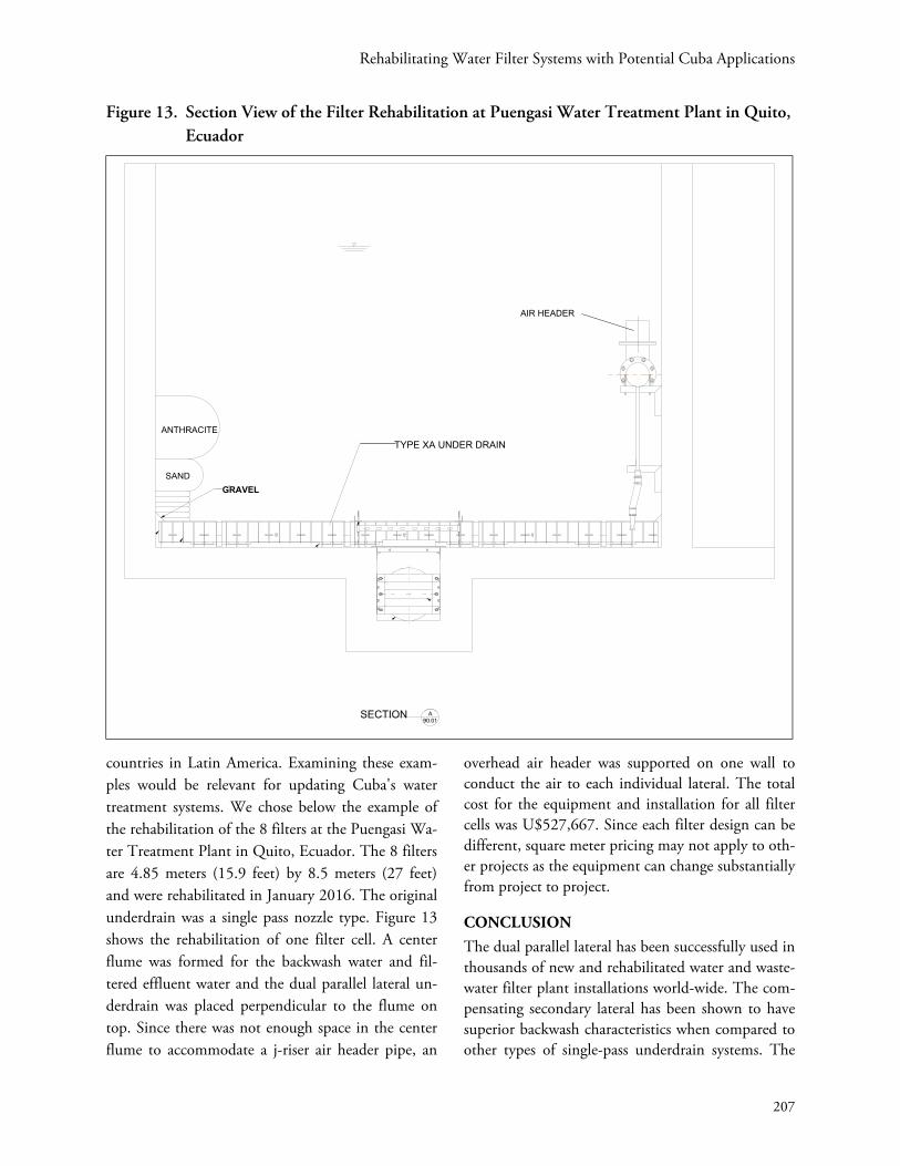
countries in Latin America. Examining these exam-ples would be relevant for updating Cuba's water treatment systems. We chose below the example of the rehabilitation of the 8 filters at the Puengasi Wa-ter Treatment Plant in Quito, Ecuador. The 8 filters are 4.85 meters (15.9 feet) by 8.5 meters (27 feet) and were rehabilitated in January 2016. The original underdrain was a single pass nozzle type. Figure 13 shows the rehabilitation of one filter cell. A center flume was formed for the backwash water and fil-tered effluent water and the dual parallel lateral un-derdrain was placed perpendicular to the flume on top. Since there was not enough space in the center flume to accommodate a j-riser air header pipe, an
overhead air header was supported on one wall to conduct the air to each individual lateral. The total cost for the equipment and installation for all filter cells was U$527,667. Since each filter design can be different, square meter pricing may not apply to oth-er projects as the equipment can change substantially from project to project.
CONCLUSIONThe dual parallel lateral has been successfully used in thousands of new and rehabilitated water and waste-water filter plant installations world-wide. The com-pensating secondary lateral has been shown to have superior backwash characteristics when compared to other types of single-pass underdrain systems. The
Figure 13. Section View of the Filter Rehabilitation at Puengasi Water Treatment Plant in Quito, Ecuador

Cuba in Transition • ASCE 2017
208
closely space orifices of the dual parallel lateral pro-vide better distribution of backwash air and water which provides better cleaning of the filter media.
The dual parallel lateral is easily used to rehabilitate existing filter boxes. A low profile block coupled with the replacement of gravel with gravel-less support plates has enabled designers to install more media or
provide a greater freeboard depth. The greater flexi-bility of the dual parallel lateral has enabled designers to meet increasingly stringent regulatory require-ments. As Cuba looks to upgrading its water treat-ment systems, dual parallel lateral might be the most efficient and cost-effective approach.
REFERENCES
Amirtharajah, A., McNeily, N., Page, G., and McL-leod, J. Optimum Backwash of Dual Media Filters and GAC Filter-Adsorbers With Air Scour, Ameri-can Water Works Research Foundation, 1991.
Beverly, P., and Morando, T. Filtration Training Manual, F. B. Leopold Co., Inc., 1997.
Cueto, J., and De Leon, O. Evaluation of Cuba’s Wa-ter and Wastewater Infrastructure Including High-
Priority Improvements and Order-of-Magnitude Costs, Association for the Study of the Cuban Economy Conference, 2010.
Kleiner, M., Snoeyink, V., Horsley M., Mayhugh, J. and Cummings, C. Comparison of Filter Back-wash Using Air Scour and Surface Wash at Deca-tur Illinois, Report, August 1989.