Reduction of Implant Loading Using a Modified Centric Occlusal
16
Reduction of Implant Loading Using a Modified Centric Occlusal Anatomy Lawrence A. Weinberg, DOS, Purpose: This paper focuses on the derivation of implant loading forces as influenced by occlusal anatomy. Vertical occlusal forces on cusp inclines produce resultant lines of force that result in laterai rather than vertical forces to the supporting bone. Materials and Methods: An analysis of resultant linos of force with different impacting occlusai surfaces was iilustrated. Methods were suggested to decrease implant loading by reducing cusp inclines, utilization of cross occlusion, and the modification of occlusal anatomy to provide a continuous ¡ .5-mm flat fossae, rather than the line angles of the usual cuspal anatomy. The relationship of incisai guidance to the cusp inciines on the adjustable articulator were reviewed. Modification of the incisai pin and articulator settings were suggested to produce a 1.5-mm fossae throughout the prosthesis. Practical laboratory and intraoral occlusal adjustment techniques were suggested to provide a modified centric occlusal anatomy to help decrease implant loading. Results: Clinical exampies were shown to verify'the accuracy of the modified settings on the semi-adjustable articulator and the resultant modified occlusal anatomy. Conclusion: Implant loading can be reduced by modifying the location of the impact area and the occlusal anatomy. Simple modification of the incisai pin and articulator settings can be used to produce a 1,5-mm flat fossae, which results in more vertical forces to the supporting bone. The same procedures are used to reduce cusp inclinations, which effectively lessens the torque exerted on the prosthesis, implant, and bone. A combination of all these factors can prevent implant overioad. lntJProsthodont!998;ll:55-69. A fter stage-two surgery, the highest incidence of failure has been attributed to implant overload.'' However, the biomechanical factors cited in the lit- erature that contribute to implant overload, such as bone type,^ cuspal inclination,' horizontal offset,^''' maxillary compared to mandibular arch,-* the inclu- sion of natural teeth within the prosthesis,^ and oc- clusal anatomy,^'^ are superimposed on physiologic variations. This prevents the isolation of a single eti- ologic factor in vivo, making scientific proof virtu- ally impossible. In the absence of such scientific proof, the study and clinical application of biome- chanical factors remains controversial. 'Former Aisoöäte Clmicsl Professor, Deparlment of Graduate Prosthodonlics. College of Dentistry. New York Universily, New York New York. Reprint request: Dr Lawrence A. Weinberg. 68 SMor, PUce. Ishndia. New York 11722. It is within this framework that the author pre- sents his opinion and rationale that the location and character of the impacting tooth surfaces affects the resultant force distribution to the prosthesis, im- plant, and supporting bone, and which thereby in- fluences success and failure. The purpose of this ar- ticle is to suggest, where clinically feasible, the modification of centric occlusal anatomy^"^ to aid lateral force reduction using a laboratory and clini- cal adjustment procedure^"^ as a practical means of reducing occlusal loading. Development of Loading Forces The application of muscle force initiates the biome- chanical loading process; however, there are many factors that alter the magnitude and quality of the force ultimately delivered to the implant and sur- rounding bone. One of the most frequently over- looked factors is the location of the applied load in 1,Numberl, 1Í 55 Tlie t me m a lio nal Journal ot Prostliodontics
Transcript of Reduction of Implant Loading Using a Modified Centric Occlusal
Reduction of ImplantLoading Using a Modified
Centric Occlusal Anatomy Lawrence A. Weinberg, DOS,
Purpose: This paper focuses on the derivation of implant loading forces as influenced by occlusalanatomy. Vertical occlusal forces on cusp inclines produce resultant lines of force that result in laterairather than vertical forces to the supporting bone. Materials and Methods: An analysis of resultantlinos of force with different impacting occlusai surfaces was iilustrated. Methods were suggested todecrease implant loading by reducing cusp inclines, utilization of cross occlusion, and themodification of occlusal anatomy to provide a continuous ¡ .5-mm flat fossae, rather than the lineangles of the usual cuspal anatomy. The relationship of incisai guidance to the cusp inciines on theadjustable articulator were reviewed. Modification of the incisai pin and articulator settings weresuggested to produce a 1.5-mm fossae throughout the prosthesis. Practical laboratory and intraoralocclusal adjustment techniques were suggested to provide a modified centric occlusal anatomy tohelp decrease implant loading. Results: Clinical exampies were shown to verify'the accuracy of themodified settings on the semi-adjustable articulator and the resultant modified occlusal anatomy.Conclusion: Implant loading can be reduced by modifying the location of the impact area and theocclusal anatomy. Simple modification of the incisai pin and articulator settings can be used toproduce a 1,5-mm flat fossae, which results in more vertical forces to the supporting bone. The sameprocedures are used to reduce cusp inclinations, which effectively lessens the torque exerted on theprosthesis, implant, and bone. A combination of all these factors can prevent implant overioad.lntJProsthodont!998;ll:55-69.
After stage-two surgery, the highest incidence offailure has been attributed to implant overload.''
However, the biomechanical factors cited in the lit-erature that contribute to implant overload, such asbone type,^ cuspal inclination,' horizontal offset,^'''maxillary compared to mandibular arch,-* the inclu-sion of natural teeth within the prosthesis,^ and oc-clusal anatomy,^'^ are superimposed on physiologicvariations. This prevents the isolation of a single eti-ologic factor in vivo, making scientific proof virtu-ally impossible. In the absence of such scientificproof, the study and clinical application of biome-chanical factors remains controversial.
'Former Aisoöäte Clmicsl Professor, Deparlment of GraduateProsthodonlics. College of Dentistry. New York Universily, NewYork New York.
Reprint request: Dr Lawrence A. Weinberg. 68 SMor, PUce.Ishndia. New York 11722.
It is within this framework that the author pre-sents his opinion and rationale that the location andcharacter of the impacting tooth surfaces affects theresultant force distribution to the prosthesis, im-plant, and supporting bone, and which thereby in-fluences success and failure. The purpose of this ar-ticle is to suggest, where clinically feasible, themodification of centric occlusal anatomy^"^ to aidlateral force reduction using a laboratory and clini-cal adjustment procedure^"^ as a practical means ofreducing occlusal loading.
Development of Loading Forces
The application of muscle force initiates the biome-chanical loading process; however, there are manyfactors that alter the magnitude and quality of theforce ultimately delivered to the implant and sur-rounding bone. One of the most frequently over-looked factors is the location of the applied load in
1,Numberl, 1Í 55 Tlie t me m a lio nal Journal ot Prostliodontics
adme and Modified Centric Occlusai Atial.imy Weinberg
Verticai resuitant iine of force
Cusp-to-tossa relationsliip
Inclined resultant lineof force
Ib O
Cusp-to-incline relationship
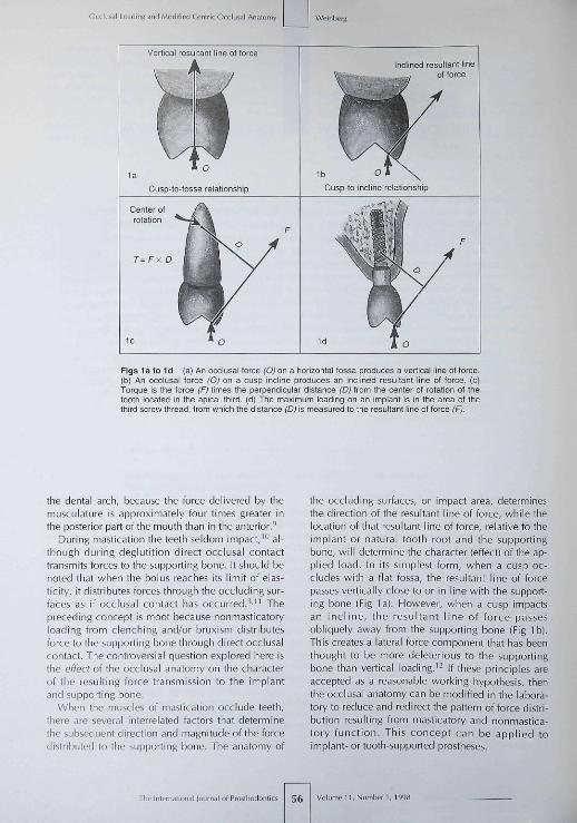
Figs la to Id (a) An occiusai torce (O) on a horizontai fossa produces a vertical iine ot torce-(b) An occiusai torce ¡O) on a cusp inciine produces an inciined resuitant line of force, (c)Tcrque is the force (F¡ times the perpendicuiar distance (D) from the center ot rotation of thetooth located in the apicai third, (d) The maximum loading on an implant is in the area of thethird screw thread, trom which the distance (Dj is measured to the resultant line ot foroe (F).
the dental arch, because the force delivered by themusculature is approximately four times greater inthe posterior part of the mouth than in the anterior.'̂
During mastication the teeth seldom impact,'° al-though during deglutition direct occiusal contacttransmits forces to the supporting bone. It should benoted that when the bolus reaches its limit of elas-ticity, it distributes forces through the occluding sur-faces as if occiusal contact has occurred.^'" Thepreceding concept is moot because nonmasticatoryloading from clenching and/or bruxism distributesforce to the supporting bone through direct occiusalcontact. The controversial question explored here isthe effecf of the occiusal anatomy on the characterof tbe resulting force transmission to the implantand supporting bone.
When the muscles of mastication occlude teeth,there are several interrelated factors that determinethe subsequent direction and magnitude of the forcedistributed to the supporting bone. The anatomy of
the occluding surfaces, or impact area, determinesthe direction of the resultant line of force, while thelocation of that resultant line of force, relative to theimplant or natural tooth root and the supportingbone, will determine the character (effect) of the ap-plied load. In its simplest form, when a cusp oc-cludes with a flat fossa, the resultant line of forcepasses vertically close to or in line with the support-ing bone (Fig la). However, when a cusp impactsan incl ine, the resultant line of force passesobliquely away from the supporting bone (Fig Ib).This creates a lateral force component that has beenthought to be more deleterious to the supportingbone than vertical loading.^^ If these principles areaccepted as a reasonable working hypothesis, thenthe occiusal anatomy can be modified in the labora-tory to reduce and redirect the pattern of force distri-bution resulting from masticatory and nonmastica-tory function. This concept can be applied toimplant- or tooth-supported prostheses.
The International lournal of Proslliodontic 56 Volumeit,Number 1,1998

Wcinbers OCCIUÍÍI Loading ^nd Moriified Centric OccliJial Anatomy
Steep incline CI,
Figs 2a lo 2c (a) With a vertical overlap antenorly. the distance (D) is greater on the maxillary implant than on the mandibular im-plant ¡a): therefore, the forque is similarly disproportional, (b) With working-side contact on the maxillary buccal cusp incline, there ismere torque on the maxillary implant than on fhe mandibular implant, as retlected by the dis proportional distances (D) and (à) fromthe resultant line ot force ¡F). (o) A steep cusp incline (Cl¡) produces a resultant line of force (F,) at a great distance (D) from the im-plant, which results in exaggerated torque. Conversely, a reduced cusp incline ("Cy produces a resultant line ot force (F^) that iscloser (d) to the implant, and thus reduces the torque.
Production oi Torque*
The measurement of torque in a natural tooth is theforce (F) times the perpendicular distance (Oj fromthe center of rotation (Fig Ic) in the apical third.^^However, the relative stiffness of titanium and alve-olar bone (compared to the flexion permitted by theperiodontal ligament! concentrates tbe maximumloading in the area of the third screw thread of theimplant^^ (Fig Id). For convenience, this maximumloading area will be used in all the illustrations.Three-dimensional finite element stress analysis'^'"*also indicates tbat inclined loading applied to theimplant (as in Fig Id) results in a concentration ofloading to the crestal bone ratber than distributionalong the entire implant surface.
There is usually more torque produced in themaxillary arcb than in the mandibular arch.'' Forexample, a vertical overlap in the anterior of themouth produces more torque in the maxilla than inthe mandible because tbe distance (D) from the re-sultant line of force is greater than the distance intbe mandible (d. Fig 2a). Posteriorly, lingual cuspalarticulation on tbe working-side occlusion is rarelyproduced in restored occlusion because of tbe lim-ited use of fully adjustable articulators. When this
•(Autlior's note) Some engineers prefer the term "moment"rather than "torque," although the terms are generally synony-mous and measured as force times the perpendicular distancefrom the center of rotation. Torque is used in ihe teî̂ t because itis thought to be more clearly understood by dentists, and is asso-ciated with a lateral force component, while moment may ob-fuscate rather than clarify an already complicated discussion.
type of occlusion occurs, tbere is more torque inthe maxillary arch tban in the mandibular arcb be-cause the resultant line of force ID) falls at a greaterdistance from the supporting bone"* id, Fig 2b).
Methods to Reduce Torque
Reduction of Cusp Inclination. One of the most sig-nificant factors in tbe production of torque is cuspinclination,^••' which can be reduced in tooth-supported as well as implant-supported prostheses.For example, with a reduction in maxillary cusp in-clination (Ci.,), the resultant line of force (F.,) fallscloser to the implant (and bone) than when there isa more acute cuspal inclination (F,, Fig 2c).
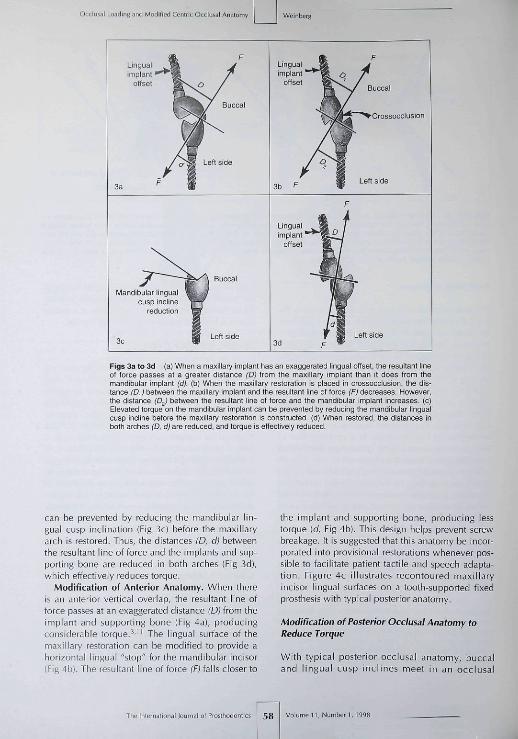
Modification of Location. With natural teeth thelocation of tbe occiusal surface may be dictated bypulpal anatomy. There is much more flexibility inthe location of the occiusal surface with an im-plant-supported prosthesis. For example, if a poste-rior maxillary implant is offset too far lingually (re-gardless of ihe cusp inclination), tbe resultant lineof force passes at a greater distance (D) from themaxillary implant and supporting bone (Fig 3a) thanit does from the mandibular implant [d. Fig 3a).
Torque can be reduced on the maxillary implantby placing the prosthesis in crossocclusion, whichdecreases the distance (D,] of the resultant line offorce from the implant and supporting bone (Fig3b¡.^ However, crossocclusion can inadvertently re-verse the situation and increase the torque on themandibular implant (or tooth) by increasing the dis-tance (D^) of tbe resultant line of force from tbe im-plant, and tbus increase the torque (Fig 3b). This
I i ,Number! ,199B The In (em alio nal lournal of Prosiliodontics
al Losriing and Modiiied Cenirit Oc
Crossooclusion
Linguaiimpiant '
offset
Mandibuiar linguacusp inciine
reduction
Figs 3a to 3d (a) When a maxiiiary implant bas an exaggerated lingual otfset, tbe resultant lineof force passes at a greater distance (Dj trom tbe maxillary implant than it does from Ibemandibular implant ¡d}. (b) When the maxillary restoration is piaoed in crossocclusion, tbe dis-tance (D.¡) between the maxiiiary implant and tfie resultant iine ot torce (Fj decreases. However,the distance ¡D^} between the resultant iine of torce and the mandibular implant increases, (c)Eievafed torque on the mandibuiar impiant can be prevented by reducing tbe mandibular lingualcusp incline before the maxiiiary restoration is oonstructed. (d) When restored, the distances inboth arches (D, d) are reduced, and torque is etfectiveiy reduced
can be prevented by reducing the mandibular lin-gual cusp inclination (Fig 3c) before the maxillaryarch is restored. Thus, the distances (D, d> betweenthe resultant line of force and the implants and sup-porting bone are reduced in both arches (Fig 3d),which effectively reduces torque.
Modification of Anterior Anatomy. When thereis an anterior vertical overlap, the resultant line offorce passes at an exaggerated distance (D) from theimplant and supporting bone (Fig 4a), producingconsiderable torque.^'" The lingual surface of themaxillary restoration can be modified to provide aborizontal lingual "stop" for the mandibular incisor(Fig 4b). Tbe resultant line of force fFJ falls closer to
the implant and supporting bone, producing lesstorque (d. Fig 4b). This design helps prevent screwbreakage. It is suggested that this anatomy be incor-porated into provisional restorations whenever pos-sible to facilitate patient tactile and speech adapta-tion. Figure 4c illustrates recontoured maxillaryincisor lingual surfaces on a tooth-supported fixedprostbesis with typical posterior anatomy.
Modification of Posterior Occiusai Anatomy toReduce Torque
Witb typical posterior occiusai anatomy, buccaland lingual cusp inclines meet in an occiusai
The International louinal of Piosthodontics Volumen,Number 1,1995

Weinberg OCCÍLMI Loading and Modified Centric Occiu^ai Anatomy
Figs 4a and 4b (a¡ Seyere torque is produced with a verticalantenor overlap. Tfie resultant line of force (F) passes at anexaggerated distance (D) from the implant. (b| A horizontal lin-gual stop on the maxillary restoration produces a more verticalline of force, which falls closer (d) to the implant and reducestorque.
Fig 4c Recontoured maxillary incisor lingual surfaces withtypicai posterior anatomy.
Fig 4d Hypothefically, fypical cuspal anatomy in a cusp-to-fossa relationship produces buccal (FJ and lingual (F^) com-ponent lines of force that combine to form a vertical resultantline of force fHFJ.
Lingual
Slight physiologic shiftin centrio occlusion
Fig 4e Physiologic variation causes individual cusp inclinecontact, which produces an inclined resultant line of force (F).
groove that provides no flat horizontal surface.From a functional standpoint, it is a misnomer tocall this groove a fossa because it is formed by twoor more inclined planes without a flat (horizontal)surface. Conventional wisdom accepts that a poste-rior "cusp-to-fossa" occlusal relationship is biome-chanically favorable. The hypothesis is that buccal(F¡¡ and lingual (F^) component lines of force (gen-erated by the cusp incline surfaces! produce a verti-cal resultant line of force (RF, Fig 4d) that is biome-chanically favorable.
This is only correct theoretically, because suchrepeatabiy precise fit is unattainable clinically be-cause occlusal contact in centric relation has been
shown to be a small area (in the range of ± 0.4mm) rather than an immutable point.'^"'^ Centricrelation has been demonstrated to vary over a pe-riod of time,^^ methods of recording,^^ and varia-tions in muscular conditioning.^ ̂ '^ As a result, theslightest physiologic variation in position will resultin only one incline contact producing a laterallyinclined resultant line of force (f. Fig 4e) (buccalcusp incline contact illustrated). In the author'sopinion, to be more compatible with physiologicvariation as described above,^^-'^ a modified cen-tric occlusal anatomy should be used to provide atrue horizontal fossa rather than iine angles (orgrooves).
• l l , N u m b e r 1 , 1998 59 The Internälionai Jojrnal of Prosihodontic
Occlus.ii Loading and Modified Centric Occlusal Anator
Oblique
1.5-mmhorizontal fossa
1.5-mm horizonlal fossa
Reduced fossa
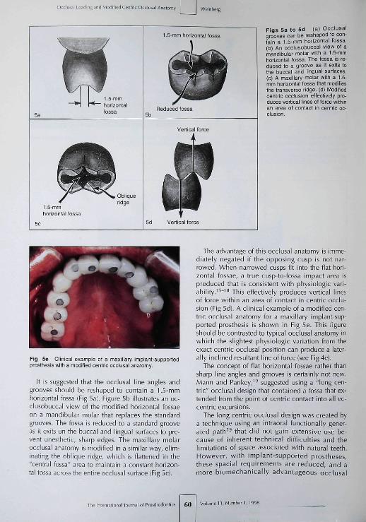
Figs 5a to 5d (a) Occlusalgrooves can be reshaped to con-fain a f.5-mm horizonfal fossa.(b) An occlusobuccal view of amandibular molar with a 1.5-mmfiorizontal fossa. The fossa is re-duced to a groove as if exifs tothe buccal and lingual surfaces.(c) A maxillary molar with a 1.5-mm horizontal fossa that modifiesfhe transverse ridge, (d) Modifiedcentric occlusion effectirely pro-duces vertical iines of force withinan area of contact in centric oc-clusion.
Fig 5e Clinical example ot a maxillary implant-supportedprosthesis with a modified centric ooolusal anatomy.
It is suggested that the occlusal line angles andgrooves should be reshaped to contain a 1.5-mmhorizontal fossa (Fig 5a]. Figure 5b illustrates an oc-clusobuccal view of the modified horizontal fossaeon a mandibular molar that replaces the standardgrooves. The fossa is reduced to a standard grooveas it exits on the buccal and lingual surfaces to pre-vent unesthetic, sharp edges. The maxillary molarocclusal anatomy is modified in a similar way, elim-inating the obiique ridge, which is flattened in the"central fossa" area to maintain a constant horizon-tal fossa across the entire occlusal surface (Fig 5c),
The advantage of this occlusal anatomy is imme-diately negated if the opposing cusp is not nar-rowed. When narrowed cusps fit into the flat hori-zontal fossae, a true cusp-to-fossa impact area isproduced that is consistent with physiologic vari-ability.'^"'^ This effectively produces vertical linesof force within an area of contact in centric occlu-sion (Fig 5d}. A clinical example of a modified cen-tric occlusal anatomy for a maxillary implant-sup-ported prosthesis is shown in Fig 5e. This figureshould be contrasted to typical occlusal anatomy inwhich the slightest physiologic variation from theexact centric occlusal position can produce a later-ally inclined resultant line of force (see Fig4e).
The concept of flat horizontal fossae ratber thansharp line angles and grooves is certainly not new.Mann and Pankey,'^ suggested using a "long cen-tric" occlusal design that contained a fossa that ex-tended from the point of centric contact into all ec-centric excursions.
The long centric occlusal design was created bya technique using an intraoral functionally gener-ated path'^ that did not gain extensive use be-cause of inherent technical difficulties and thelimitations of space associated witb natural teeth.However, witb implant-supported prostheses,these spacial requirements are reduced, and amore biomechanically advantageous occlusal
The Internatiaral lournal of Prosthodonlits 60
Occiusal Loading and Modified Centric Occiussi Anatomy
Modification otincisai pin
6d
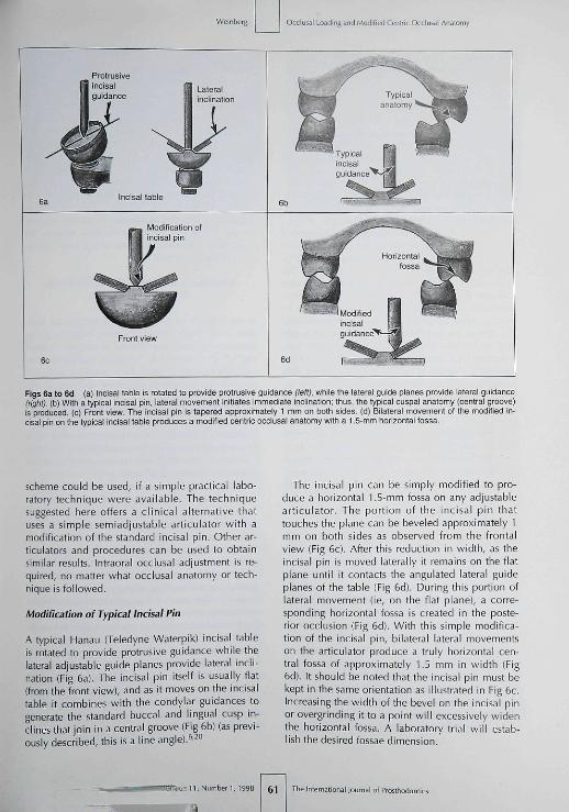
Figs 6a to 6d (a) incisai tabie is rotated to provide protrusive guidance (left), while the laleral guide pianes provide iaterai guidance(rigfit). (b) With a typicai incisai pin, lateral movement initiates immediate inclination; thus, the typicai cuspal anatomy (central groove)is prcduced. (c) Front view The incisai pin is tapered approximately 1 mm on both sides (d) Biiateral movement ol the modified in-cisai pin on ttie typical incisai tabie produces a mcdified centric occiusal anatcmy with a 1.5-mm honzontai tossa.
scheme could be used, if a simple practical labo-ratory technique were available. The techniquesuggested here offers a clinical alternative thatuses a simple semiadjustable articulator with atnodification of the standard incisai pin. Other ar-ticulators and procedures can be used to obtainsimilar results. Intraorai occiusal adjustment is re-quired, no matter what occiusal anatomy or tech-nique is followed.
Modification of Typical Incisai Pin
A typical Hanau (Teledyne Waterpik) incisai tableis rotated to provide protrusive guidance while thelateral adjustable guide planes provide lateral incli-nation (Fig 6a). The incisai pin itself is usually flat(from the front view), and as it moves on the incisaitable it combines with the condylar guidances togenerate the standard buccal and lingual cusp in-clines that join in a central groove (Fig 6b) (as previ-ously described, this is a line angle). '̂̂ o
The incisai pin can be simply modified to pro-duce a horizontal 1.5-mm fossa on any adjustablearticulator. The portion of the incisai pin thattouches the plane can be beveled approximately 1mm on both sides as observed from the frontalview (Fig 6c), After this reduction in width, as theincisai pin is moved laterally it remains on the flatplane until it contacts the anguiated lateral guideplanes of the table (Fig 6d). During this portion oflateral movement (ie, on the flat plane), a corre-sponding horizontal fossa is created in the poste-rior occlusion (Fig 6d). With this simple modifica-tion of the incisai pin, bilateral laleral movementson the articulator produce a truly horizontal cen-tral fossa of approximately 1.5 mm in width (Fig6d). It should be noted that the incisai pin must bekept in the same orientation as illustrated in Fig 6c.Increasing the width of the bevel on the incisai pinor overgrinding it to a point will excessively widenthe horizontal fossa. A laboratory trial will estab-lish the desired fossae dimension.
: 1 1 , Number ],199B 61 i of Prostliodonlii

Occiusal Loading anrt Mmlified Centric Ocdusal Anatomy
Modification of Typical SemiadjustableArticulator Settings
Most clinicians do not use a completely adjustablearticulator^" witb ihe required three-dimensionalrecords. Furthermore, tbe vast majority of restora-tions are completed on a straight-line articulator,and when a semiadjustable instrument is used, itrarely is used to its maximum potential. It is sug-gested tbat semiadjustable instruments should bereevaluated as a practical means of producing hori-zontal fossae (with vertical resultant forces) ratbertban occiusal grooves tbat most often produce lat-eral inclined forces (torque).
A typical face-bow mounting is recommendedusing the notcb on tbe incisai pin (FHanau) or anyof the accepted anterior-third points of referencethe clinician prefers (infraorbital rim, ala of thenose, etc). This procedure is acceptable becausechanges in vertical height of the occiusal plane,measured at the incisors in tbe magnitude of ± 16mm, produce an occiusal change of approximately0.2 mm at tbe first molar nonworking cusp heightand no occiusal change on the working side (cal-culations for a 3-mm cusp widtb).-" Because of thegeometry, changes in patient dimensions have littletangible effect on the nonworking-side cusp in-clines, and no effect on tbe working-side cusp in-clines wben the face-bow is elevated or lowered asdescribed.
Semiadjustable articulators use protrusive checkbite records to establish protrusive condyiar incli-nation. However, since these instruments do notusually bave an adjustable intercondylar distance,lateral check bite records would be difficult totransfer accurately.^° In lieu of lateral records, theBennett angle (medial anguiation of the nonwork-ing [balancing! condyle) has been calculated byformula (Hanau)^°"^^ without verification of its de-rivation, Tbis procedure on the articulator is themecbanism tbat provides the lateral Bennett move-ment of the working condyie. FHowever, in tbe au-thor's experience, the working posterior cusp incli-nations that are produced with this metbod areusually too flat (negative error).^^ Tbis negativeerror can be corrected by eliminating the lateralBennett movement on the articulator.^^
The relationship between the extreme guidances(condyiar guidances and incisai guidance) andcusp inclination on diversified articulators hasbeen evaluated matbematically.^" On the basis oftbese mathematical calculations and long clinicalexperience, the author recommends modificationof the typical semiadjustable articulator techniques
to correct their deficiencies and provide im-proved, practical, cost-effective results.^' The pos-terior working-side negative error, associated withtypical settings containing a lateral side sbift, canbe corrected by simply eliminating tbe Bennettangle on tbe instrument (rotating tbe condyiarposts laterally to 0). This will increase tbe poste-rior working cusp inclines. For example, Fig 7a il-lustrates the completed restorations on tbe instru-ment in working-side relationsbip. Figure 7bshows the restorations intraorally in tbe sameworking-side relationship. No matter tbe preferredconcept of occlusion, nor the extent or type ofrestoration, this simple adjustment on the articula-tor (no lateral side sbift) significantly reduces thechair time required for intraorai occiusal adjust-ment of the prosthesis.
Importance of Centric Occlusion VersusEccentric Occlusion
In the author's opinion, there is a conceptual deci-sion to be made before choosing between groupfunction and canine-protected occlusion ("cuspidrise").^'' The question is, "Is centric occlusion a pre-cise position or a small area resulting from thephysiologic variability of centric relation, as de-scribed in the literature?"'^"^^ If a clinician believescentric occiusal contact should be a nonvariable,precisely replicable point, then a canine-protectedocclusion might logically obviate tbe need for aposterior scheme of occlusion designed to limit lat-eral forces. One need only be concerned about thepatient's clenching or bruxism.
FHowever, if a clinician agrees with the researchthat describes centric relation as having physio-logic variability influenced by muscle tone, headposition, time of day or over several days, andmuscle conditioning, then centric occlusai contactshould not be anatomically locked into one preciseposition. Centric occiusal contact should provide a5mall area of simultaneous harmonious contact, re-gardless of the occlusai scheme used for eccentriccontact. The size of that area and the clinicalmethods to obtain it are influenced by tbe occiusalspace available, wbether a tootb-supported or animplant-supported prosthesis is planned, and thepreference and skill of the clinician.
In the author's opinion, the choice betweengroup function or canine-protected occlusion de-pends on specific individual prosthodontic factorsas well as the clinician's preference and is far lessimportant tban tbe type of centric occlusai contactprovided for the patient.
The International Journal of Fn^slliodontics 62 Volume 11, Number 1, t99a

Weinberg iusai Loading and Modified Centric Occiusai Anatomy
Fig 7a Working-side ocolusal relationsbip on the articuiator. Fig 7b Infraoral view of tbe working-side occiusai reiationsbip.
Laboratory Articulator Concepts and Technique
When the lateral guiding inclines are "harmonious"(Fig 8a), nonworking-side contact will be producedduring lateral excursions (Fig 8b). Most clinicianssuggest tbat nonworking-side contact should beavoided in restorative dentistry. Occiusai problemscan be avoided by simple preplanning and preven-tative correction.
Nonworking-side contact can be avoided bycorrection of the opposing occlusion beforerestorative procedures are instituted. This proce-dure will also prevent the possible loss of centricocciusai contact as well as unnecessary occiusaidisharmony. For example, prevention of nonwork-ing-side contact in the final maxillary implant-supported restoration (on the patient's left side asshown in Fig 8b) is accomplished by reducing theopposing mandibular buccai cusp incline (Fig 8c)before restorative procedures are instituted on theopposing (maxillary) arch. The maxillary implant-supported provisional restoration is fabricatedagainst tbe reduced mandibular buccal cusp in-cline to provide good centric contact (Fig 8d).Nonworking-side freedom is confirmed wben thepatient moves into right lateral excursion (Fig 8e).
Tbe final restoration is then predictably con-structed on tbe articulator.
It is a cardinal principle in restorative prostbodon-tics that whenever possible, all esthetic and func-tional pianning should be carried out on the provi-sional prosthesis.-'' This procedure provides estheticapproval by the patient, ensures correct results, andprovides an important therapeutic trial. It also pro-vides an opportunity for correction of the plannedincisai guidance in the provisional prosthesis. Whenthe provisional prosthesis is acceptable, it also pro-vides a method of transference of the esthetics andcorrected incisai guidance to the articulator for thefinal prosthesis.̂ '̂̂ ^
Practicai Teciinique for Obtaining 1.5-mmOcciusai Fossae in the Maxiiiary Arch
Tbe guiding cusp inclines for lateral excursions arewell understood as sbown in Fig 8a. FHowever, if a1.5-rTim fossa is planned for the maxillary arch op-posing unrestored standard occiusai anatomy inthe mandibular arch, the modified incisai guidance(as previously described in Fig 6d), will removecentric contact on the maxillary lingual cusps. Themechanism of this process is as follows:
1,Number 1,1998 63

Occlusal Loading and Modified Centric Occlusal Analorr
Working sideNonworking side
Right lateral
Lingua
Reduced mandibular buccalcusp incline Non working-side guidance
Right lateraNon working-side
clearance
Figs 8a to Be (a) Typical lateral guiding inclines are shown in centric occlusion, (b) When the lateral guid-ing inclines are "harmonious," nonworking-side contact is produced, (c) Opposing mandibular buccal cusp in-cline is reduced before the maxiilary restoration is fabricated, (d) Maxillary left restoration is restored to thecorrected mandibular occlusal anatomy, which reduces the nonworking-side guidance, (e) During right lateralmovement, nonworking-side ciearance is produced.
The interna liona i i of Fn55fhodontl( 64 •11 , Numberi, Í99S
Weinberg ILMI LosdinR and Modified Centrrc Occiuial Anatomy
Centric occlusion
I 111 iim I f iMii' I I J
Working side
Lingual
Maxillary lingualsurface reducfion
Horizontal fossa and Modified incisaimaxillary buce a i cusp guidance
incline
Nonworking side Centric ooolusion
Lingual
Maxillary lingualcusp inclinereducfion
Lingual
Loss of maxillarycentric-maintaininElingual cusp
Modified incisai<u ida nee
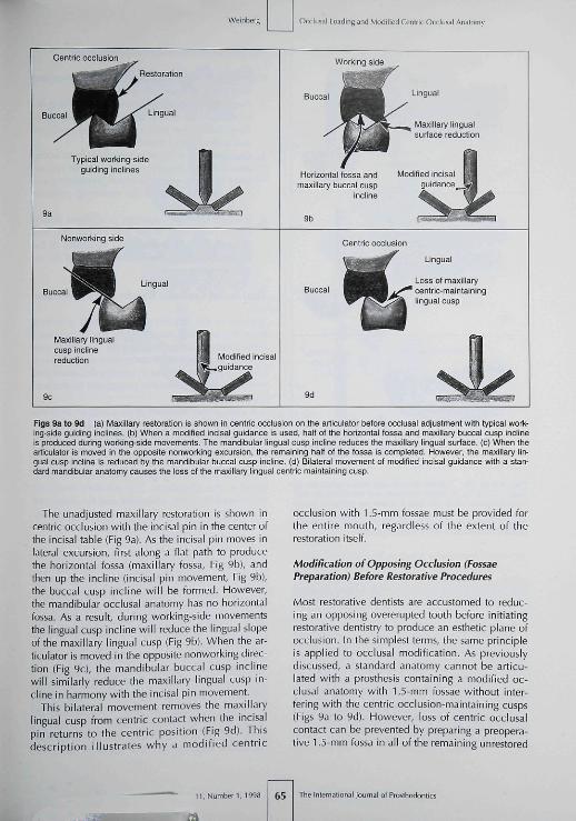
Figs 9a to 9d (a) Maxillary restoration is shown in centric occlusion on the articulator before occlusal adjustment with typical work-ing-side guiding inclines, (b) When a modified incisai guidance is used, half of the horizontal fossa and maxillary buccal cusp inclineis produced during working-side movemenfs. The mandibular lingual cusp incline reduces fhe maxillary lingual surface, (c) When fhearficulator is moved iti fhe opposife nonworking excursion, the remaining half of the fossa is completed. However, the maxillary lin-gual cusp incline is reduced by fhe mandibular buccal cusp incline, (d) Bilateral movement of modified incisai guidance with a stan-dard mandibular anafomy oauses fhe loss of the maxillary lingual cenfric maintaining cusp.
The unadjusted maxiilary restoration is shown incentric occlusion with the incisai pin in the center ofthe incisai table (Fig 9a). As the incisai pin moves inlateral excursion, first along a flat path to producethe horizontal fossa (maxillary fossa. Fig 9b), andthen up the incline (incisai pin movement. Fig 9bl,the buccal cusp incline will be formed. However,the mandibular occlusal anatomy has no horizontalfossa. As a result, during working-side movementsthe lingual cusp incline will reduce the lingual slopeof the maxillary lingual cusp (Fig 9b). When the ar-ticulator is moved in the opposite nonworking direc-tion (Fig 9cl, the mandibular buccal cusp inclinewill similarly reduce the maxillary lingual cusp in-cline in harmony witb the incisai pin movement.
This bilateral movement removes the maxillarylingual cusp from centric contact when the incisaipin returns to the centric position (Fig 9d). Thisdescription illustrates why a modified centric
occlusion with 1.5-mm fossae must be provided forthe entire mouth, regardless of the extent of therestoration itself.
Modification of Opposing Occiusion (FossaePreparation) Before Restorative Procedures
Most restorative dentists are accustomed to reduc-ing an opposing overerupted tooth before initiatingrestorative dentistry to produce an esthetic plane ofocclusion. In the simplest terms, the same principleis applied to occlusal modification. As previouslydiscussed, a standard anatomy cannot be atlicu-lated with a prosthesis containing a modified oc-clusal anatomy with 1.5-mm fossae without inter-fering with the centric occlusion-maintaining cusps(Figs 9a to 9d). However, loss of centric occlusalcontact can be prevented by preparing a preopera-tive 1.5-mm fossa in all of the remaining unrestored
1l,Number I,1 65 The International Joiirnai of Pfosthodontics
Occlusai Loading and Modified Centiic Occiusal Anatomy
Centric occlusion
Pin rises oft •incisai table
Prolrjsive positicn
100
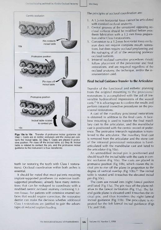
Figs 10a to 10c Transfer of protrusive incisai guidance: (a)Step I. Casts are in centric occiusion and the incisai pin con-tacts the mcisal tabie. (b) Step il. Casts are placed in protru-sive position. Pin rises off the incisai table, (c) Step lil. Incisaitable is rotated to conlact the pin, and the protrusive incisaiguidance tc the instrument is thus transferred.
teeth (or restoring the teeth with Class I restora-tions). Occiusal coordination within both arches isessential.
It should be noted that most patients requiringimplant-supported prostheses (or extensive tooth-supported prostheses), already have many restora-tions that can be reshaped to coordinate with amodified centric occiusal anatomy containing 1.5-mm fossae. For patients with extensive enamel sur-faces that would require correction, the restorativedentist can make the decision whether additionalClass I restorations are justified to gain the advan-tages of reduced implant loading.
The principles of occlusai coordination are:
1. A 1.5-mm horizontal fossa cannot be articulatedwith standard occiusal anatomy.
2. Central grooves of the unrestored opposing oc-ciusal surfaces should be modified before pros-thesis fabrication with a 1.5-mm fossa prepara-tion and/or Class 1 restorations.
3. Conversion to a 1.5-mm horizontal fossa occlu-sion does not require complete mouth restora-tions, but does require occiusal preplanning andthe reshaping of all of the remaining posteriorocciusal surfaces.
4. Intraorai occiusal corrective procedures shouldfollow placement of the provisional and finalrestorations, and are required regardless of theocciusal anatomy, the technique, and/or the in-strumentation used.
Final Incisai Guidance Transfer to the Articulator
Transfer of the functional and esthetic planningfrom the original mounting to the provisionalrestorations is accomplished with the aid of irre-versible hydrocolloid impressions of the waxedcasts.̂ •'' It is advantageous to confirm the results andperform intraorai corrective procedures on the pro-visional restorations.
A cast of ihe maxillary provisional restorationsis obtained in addition to the final casts. A face-bow mounting is used to transfer the final maxil-lary cast to the articulator, and the mandibularcast is positioned with the centric record of prefer-ence. The protrusive interarch registration is trans-ferred to the aniculator. The maxillary final castis removed from the articulator and the stone castof the intraorai provisional restoration is hand-articulated with the mandibular cast and luted tothe articulator (Fig 10a).
An unmodified incisai pin is positioned andshould touch the incisai table with the casts in cen-tric occlusion (Fig 10a). The casts are placed inprotrusive position (Fig 10b), which causes the in-cisal pin to rise off the plane in proportion to thedegree of vertical overlap (Fig lOb).^^ The incisaitable Is rotated until it touches the elevated incisaipin (Fig 10c).
The casts are moved into (right) lateral positionand luted (Fig 11a). The pin rises off the plane rel-ative to the lateral inclination (Fig 11a). The lat-eral guide plane is elevated until it touches the in-cisal pin, and thus transfers the right lateralincisai guidance (Fig l i b ) . The procedure is re-peated for the left lateral incisai guidance (FigsI i c a n d l i d ) .
The internationai Journai of Prosthodontics 66 Volume I I , Number 1, 1998
jnd Modified Centric Occlusai Anaromy
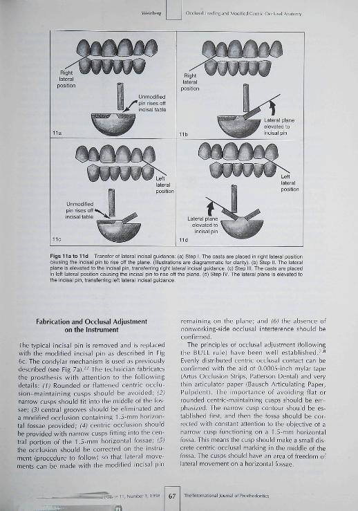
Figs 11 a to l id Transfer of lateral incisai guidance: (a] Step 1 The casts are placed in right lateral positioncausing the incisai pin to rise off the plane. (Illustrations are diagrammatic tor clarity], (b¡ Step II. The lateralplane is elevated to the incisai pin. transfernng nght lateral incisai guidance, (c] Step III. The casts are placedin left lateral position causing the incisai pin to rise off the plane (d¡ Step IV The lateral plane is elevated tothe incisai pin, transferring left lateral incisai guidance.
Fabrication and Occiusal Adjustmenton the Instrument
The typical incisai pin is removed and is replacedwith the modified incisai pin as described in Fig6c. The condyiar mechanism is used as previouslydescribed (see Fig 7a¡.^^ The technician fabricatesthe prosthesis witb attention to the fol lowingdetails; (1) Rounded or flattened centric occlu-sion-maintaining cusps sbould be avoided; (2)narrow cusps should fit inio the middle of the fos-sae; (3) central grooves should be eliminated anda modified occlusion containing 1.5-mm horizon-tal fossae provided; (4) centric occlusion shouldbe provided with narrow cusps fitting into the cen-tral portion of the 1.5-mm horizontal fossae; (5)the occlusion should be corrected on tbe instru-ment (procedure to follow) so that lateral move-ments can be made with the modified incisai pin
remaining on tbe plane; and (6) the absence ofnonworking-side occiusal interference should beconfirmed.
The principles of occlusai adjustment (followingthe BULL rule] have been well established.'''^Evenly distributed centric occiusal contact can beconfirmed with the aid of 0.0005-inch mylar tape(Artus Occlusion Strips, Patterson Dental] and verythin articulator paper (Bausch Articulating Paper,Pulpdent). The importance of avoiding flat orrounded centric-maintaining cusps should be em-phasized. The narrow cusp contour sbould be es-tablished first, and then the fossa should be cor-rected with constant attention to the objective of anarrow cusp functioning on a 1.5-mm horizontalfossa. This means the cusp should make a small dis-crete centric occiusal marking in the middle of thefossa. The cusps should have an area of freedom oflateral movement on a horizontal fossae.
67 Journal of Prosthodontics

Occiusai Loading and Modified Centric Occliiial Analomy
The incisai edges of the mandibular anterior teetharticulate with a narrow horizontal lingual stop onthe lingual surfaces of the maxillary anterior teeth,as described in Fig 4b. FHowever, without furtherocciusai adjustment, anteroposterior freedom ofmovement on a horizontal plane is prevented,which, in effect, would lock tbe occlusion into themost retruded border position of centric relationand defeat the concept tbat centric occiusai contactis an area caused by physiologic variability.
Laboratory Occiusai Adjustment Procedures
Skilled technicians can adjust standard lateral move-ments on an articulator and maintain contact of theincisai pin on tbe plane during lateral movements.The principles are exactly the same for modifiedcentric occlusion with 1.5-mm fossae, except moretime and care are needed. It is more a matter of un-derstanding the concept and visualizing the objec-tive than the need for superskilled expertise.
Modified centric occlusion is completed on the ar-ticulator as previously described. Centric occlusion ismarked with one color (blue, for example). A differ-ent-colored articulating paper is placed, and the in-strument is moved into right and left lateral excur-sions. The centric occlusion points are meticulouslymaintained while the lateral areas are adjusted untiltbe incisai pin remains on the plane during both lat-eral excursions. With a little experience, modifiedcentric occlusion with 1.5-mm fossae can be pro-duced efficiently. Tbe articulator settings and modi-fied incisai guidance (see Figs 6c and 6d) create theocciusai anatomy in the same manner as typical oc-ciusai configurations {see Figs 6a and 6b).
Since the technique described in this reportstrives to provide a small area of contact rather thanpoint contact for centric occlusion, an appropriateamount (0.5 mm) of freedom of movement shouldbe provided anterior to centric occiusai contact. Ineffect, tbe 1.5-mm horizontal fossa is extended an-teriorly to prevent locking of the occlusion into themost retruded border position of centric relation.This can be accomplished in several ways, but issimplest to achieve after modified centric occlusionhas been fabricated pnsteriorly for bolb lateral ex-cursions. The incisai table is rotated to its originalhorizontal position (0 degrees), and 0.5 mm of pro-trusive freedom of movement is accomplished onthe articulator by occiusai adjustment. With the aidof the two-color marking system, centric contactcan be maintained.
For those clinicians who favor a canine-protectedocclusion, the author suggests the provision of somedegree of freedom of movement on the horizonlalfossae in centric occlusion prior to eccentric excur-
sions. The author does not underestimate the clinicaldifficulties encountered in applying this concept toocclusion with steep vertical overlap of the naturalteeth; however, with implant-supported prostbeses,the increased available space removes this obstacle.
To provide a harmonious protrusive excursionanterior to tbe established 0.5 mm, protrusive guid-ance on the incisai table sbould be reset as pre-viously described (see Figs 10a to 10c). The res-torations should be adjusted for harmoniousprotrusive excursions with the two-color markingsystem to preserve centric occiusai contact.
Intraorai Occiusai Adjustment
To efficiently correct centric occlusion deflectivecontacts, 0.0005-inch mylar strips held in a hemo-stal are placed between each contacting cusp. Thepatient must be instructed to maintain contact andnot release occiusai pressure on the mylar strip as itis pulled laterally. This procedure can easily identifythe offending cusp. Once identified, tbin articulatorpaper is used to mark the completely dry occiusaisurfaces. Pressure-indicating marking tape {Micro-O-Reg, Pulpdent) used on completely dry occiusai sur-faces will further differentiate those areas requiringrefinement. Although tbe patient may tap tbe teethtogether firmly, the pressure-marking tape will indi-cate only the deflective areas. Conversely, when thecorrection process is completed, tbe contactingareas will bave discrete markings, indicating anevenly distributed occiusai contact.
In the author's clinical opinion, the centric occlu-sion adjustment technique should vary dependingon the type of prosthesis support. When completetooth-supported or complete implant-supportedprostheses are adjusted, the technique should besimilar because tbe supporting structures have com-parable stiffness and/or flexion.''•^^
Problems arise when a free-standing implant-sup-ported prosthesis functions in the same arch as nat-ural teeth. These difficulties result from the differ-ences in the relative flexion provided by theresilience of ihe periodontal ligament compared tothe stiffness of implants and bone. Therefore, withligbt occiusai contact the natural teeth and implant-supported prostbesis may have relatively even load-ing. FHowever, as more occiusai pressure is applied,the periodontal ligament resilience shifts the load tothe implants, which provide extremely stiff support.Special occiusai adjustment techniques are re-quired ihat are not possible to account for on thearticulator, where everything is equally rigid.
A principle can be Stated that whenever twostructures of dissimilar flexion and stiffness are tiedtogether or interact occlusally, tbe structure witb the
Tlie International lournal of Froslhodontii 68 Volumen,Number i ,1998
Occlusai Loading and Modiiicd Centric Occlusal Anatomy
greatest stiffness bears much more of the ioad.^'^^Currently there is no "scientific" way to adjust theocclusion for dissimilar flexion and stiffness of intra-oral supporting structures. The technique suggestedhere is anecdotal and based on empirical clinicalexperience in the attempt to solve a difficult clinicalproblem to prevent implant overload.
First, the occlusion is adjusted until there is evenresistance to pulling on the 0.0005-inch mylar tapebetween the free-standing implant-supported pros-thesis and the natural teeth. Then the adjustmentprocess is continued only on the implant-supportedprosthesis until the tape can just be pulled throughwith a slight drag without catching. Pressure-mark-ing tape (with the patient tapping forcefully on dryocclusal surfaces) should leave no markings on theimplant-supported prosthesis. This process may berequired annually, since natural teeth change theirposition in bone, while observations so far indicatethat osseointegrated implants do not migrate.
Intraoral eccentric occlusal adjustment follows thewell-established two-color marking procedures,*"'̂ '̂ ^with the exception that special care is required tomaintain harmonious centric occlusal contact overthe area of the 1.5-mm fossae.
Summary
The hypothesis was presented that loading forces onan implant and supporting bone are influenced bythe anatomy of the occluding surfaces (impact area).The resultant lines of force are usually inclined later-ally rather than vertically because a true cusp-to-hor-izontal fossa seldom exists. Physiologic variability ofcentric relation aiso suggests a small area of centricocclusion, rather than a precise contact, would helpreduce implant loading. Several methods have beensuggested to reduce lateral forces on implants andsupporting bone by altering the occlusal positionand/or decreasing cusp inclines; however, to accom-plish more favorable vertical lines of force, a modi-fied occlusal anatomy containing 1.5-mm horizontalfossae instead of occlusal grooves has been recom-mended for posterior prostheses. The opposing cuspsshould be narrowed, which will produce a true cusp-to-horizontal fossa relationship in a practical range ofmotion from the point of centric contact-Modification of typical semiadjustable articulatorprocedures were recommended to produce these re-sults in a simple, practical, and cost-effective man-ner. Intraoral occlusal adjustment techniques havebeen described for the modified occlusal restorationscontaining 1.5-mm horizontal fossae.
References
1. Smith DC Dental implanls: Materials and design considera-tions. Ini | Proslliodont 1993;6:IO6-117.
2. ]affin RA, Berman CL. The excessive loss of Brânemaik fixturesin Type IV bone; A 5-year analysis. | Periodontol 1991 ;62 :2^ .
3. Weinberg LA, Krtjger B. A comparison of implant/prostliesisloading with four clinical variables. Int J Prosthodont 1995;8:421^33.
4. Weinberg LA, Kruger B. An evaluation of lorque (moment] onimpiant/prosthesis with staggered buccal and lingual offset, IntI Periodont Rest Dent 1996;16:253-265.
5. Weinberg LA, Kruger B, Siomechanical considerations whencombining tooth-supported and implant-supported proslheses.Oral Surg Oral Med Oral Pathol 1994;7e:22-27.
6. Schtjyier CH. Evaluation of incisai guidance and its influencein restorative dentistry. I Prosthet Dent 1959;9:374-378.
7. Schuyler CH. Correction of occiusal disharmony of the naturaidentition. N V State DenlJ 1947;13:445-^62.
8. Weinberg LA. Rationale and technique for occiusal etiuilibra-tion. I Prosthel Dent 19&4;14:74-e6.
9. Ltjndeen D, Laureii L. Occlusal forces in prosthetically re-stored dentitions: A methodologicai study, ) Orai Rehabil1984:11:29-37.
10. PosseitU, Studies in the rnobility of the human mandibie. ActaOdontoi Scand l952;1Olsuppl):1O-l9
11. Weinberg LA. Axial inclination and cuspai articuialion m rela-tion to force distribution. | Prosthet Dent 1957,7:804-813.
12. Misch CE. Contemporary Implant Dentistry. St Louis: Mosby,1993:281-382.
13. Clelland NL. Ismail YH. Zaki HS, Pipko D. Three-dimensionalfinite element stress analysis in and around the Screw-Vent im-plant. Int I Oral Maxiiiofac Implants 1991:6:391-398.
14. iieiger MR, Mayberry M, Brose MO, Finite element analysis ofsix endosseous implants. J Prosthet Dent l990;63:671-676.
15- Grasso |, Sharry J. The duplicability of arrow-point tracing indentuious subjects. | Prosthet Dent 1968:20:106-115.
16. Kantor M, Silverman S, Garfiiii<el L. Centric relation recordingtechniques: A comparative investigation. J Prosthet Dent 1972;28:593-600.
17. Calagna L, Silverman S, Garfinkei L, Influence of neuromuscu-lar conditioning on centric relation registrations. | ProithetDent I973;30:598-604.
16. Ceienza FV. The centric position: Repiacement and character.I Prosthet Dent 1973:30:591-598.
19. Mann A, Paniiey L. Oral réhabilitation. II. Reconstruction ofthe upper teeth using a functionally generated path technique.I Prosthet Dent 1960;10:151-162,
20. Weinberg LA. EvalLtation of basic articuiators and their con-cepts. I Prosthet Dent 1963;l.3:622-644,645-663,a7.î-BHIl,1038-1054.
2 1 . Stuart CE, Stallard H. Principles Involved in restoring occlusionto natural teeth. | Piosthet Dent 1960;10:304-3I3.
22. Weinberg LA. An evaiuation of the face-bow mounting. |Prosthet Den t l96 l :11 :32^2 .
13. Weinberg i_A. Alias of Crown and Bridge Prosthodontics. St.Louis: Mosby, 1965:283.
24. D'Amico A. Functional occiusion of the natural teeth of man ]Prosthet Dent 1961 ;11:899-915 .
25. Weinberg LA. Functionai and esthetic planning for full cover-age, I Am Dent Assoc 1963:66:42-52.
26. Weinberg LA. The biomechanics of force distribution in im-plant-supported prosthesis. Int | Oral Maxiiiofac Implants1993:019-31.
i l l ,Number! , I99S 69 The International Journal of Pvosthodontics