Red Wing Bridge Bridge 9040 Concept Evaluation Report 4-24 ...
122
Transcript of Red Wing Bridge Bridge 9040 Concept Evaluation Report 4-24 ...


MnDOT Red Wing Bridge TH 63 over the Mississippi River
Bridge Concept Report
January 2014 REVISED April 2014
Prepared by HDR Engineering, Inc.

BRIDGE CONCEPT REPORT i January 2014
TableofContentsPurpose and Background .............................................................................................................................. 1
General Design Considerations and Criteria ................................................................................................. 1
Structure Limits and Alignment ................................................................................................................ 1
Grade ......................................................................................................................................................... 2
Typical Roadway Sections ......................................................................................................................... 2
Cost Estimates ........................................................................................................................................... 3
Vertical Clearances .................................................................................................................................... 3
Horizontal Clearances ............................................................................................................................... 4
Aesthetics and Context Sensitive Design .................................................................................................. 5
Maintenance of Traffic During Construction ............................................................................................ 6
Removal Strategy ...................................................................................................................................... 6
Aviation ..................................................................................................................................................... 7
Future Expansion ...................................................................................................................................... 7
Bridge Type Alternates .................................................................................................................................. 8
Alternate 1 – Tied Arch ............................................................................................................................. 9
General Description .............................................................................................................................. 9
Constructability ................................................................................................................................... 15
Inspection and Maintenance .............................................................................................................. 16
Costs .................................................................................................................................................... 17
Risks .................................................................................................................................................... 17
Advantages and Disadvantages .......................................................................................................... 17
Alternate 2 – Steel Box Girder ................................................................................................................ 18
General Description ............................................................................................................................ 18
Constructability ................................................................................................................................... 25
Inspection and Maintenance .............................................................................................................. 27
Costs .................................................................................................................................................... 28
Risks .................................................................................................................................................... 28
Advantages and Disadvantages .......................................................................................................... 29
Alternate 3 – Concrete Box Girder .......................................................................................................... 30
General Description ............................................................................................................................ 30

BRIDGE CONCEPT REPORT ii January 2014
Constructability ................................................................................................................................... 34
Inspection and Maintenance .............................................................................................................. 35
Costs .................................................................................................................................................... 36
Risks .................................................................................................................................................... 37
Advantages & Disadvantages .............................................................................................................. 37
Summary ..................................................................................................................................................... 37
List of Appendices
Appendix A Concept Profiles
Appendix B Bridge Section Comparisons
Appendix C Concept Cost Estimates
Appendix D New Structure Alternatives Memo
Appendix E Tied Arch Details
Appendix F U.S. Coast Guard Clearance Envelope Documents
Appendix G Visual Considerations – Bridge 9040 New Structure Types
Appendix H Supplemental Web Depth Study

BRIDGE CONCEPT REPORT i January 2014

BRIDGE CONCEPT REPORT 1 JANUARY 2014
PurposeandBackgroundMnDOT initiated the Red Wing Bridge Project in January 2012. The project includes the US 63
(Eisenhower) Bridge 9040 over the Mississippi River and the US 63 Bridge 9103 over US 61, as
well as the highway connections to US 61, Minnesota TH 58, and approach roadways in the
State of Wisconsin. The Eisenhower Bridge carries US 63 across the river from Red Wing and
connects to the State of Wisconsin. The bridge provides the only regional crossing of the river
for over 30 miles upstream or downstream for several communities on both the Wisconsin and
Minnesota sides of the river.
This report addresses three concepts for replacing Bridge 9040. The bridge is proposed for
replacement due to a number of factors. These include a low sufficiency rating due to uneven
foundation settlement, excessive longitudinal movement, and poor deck condition.
Seven bridge concepts were originally identified as potential alternatives during the preliminary
screening process. Three of these were subsequently chosen to continue on in the process as
the most suitable based primarily on the site requirements, cost effectiveness, and stakeholder
input (see “New Structure Alternatives Memo” dated March 4, 2013 in Appendix D). These
three were the Tied Arch, the Steel Box Girder, and the Segmental Concrete Box Girder.
This report will evaluate the three bridge replacement concepts for Bridge 9040 with respect to
general design considerations and criteria established through consultation with the bridge
owners and stakeholders. Finally, a matrix is provided that captures the critical information for
each concept.
GeneralDesignConsiderationsandCriteria
StructureLimitsandAlignmentThe three bridge alternatives discussed in this report will be situated immediately upstream of
the existing alignment of Bridge 9040. Total bridge lengths are held close to the current bridge
length of 1625’.
During the initial review of the project, several alternate alignments crossing the Mississippi
River were considered for US 63. These included relocations of the US 63 crossing upstream
approximately one mile at Bench Street, and downtown alignments at Plum Street, Bush Street,
and Broad Street.
The upstream concepts were considered because it was originally believed there might not be
sufficient area on either side of Bridge 9040 to build foundations for a new bridge. The further
BRIDGE CONCEPT REPORT 2 JANUARY 2014
upstream alternatives were removed from consideration because they had undesirable social,
economic, and cultural impacts.
The proposed realignment of US 63 is immediately upstream of the in place alignment. The
proposed alignment will be parallel to the existing alignment and located between the existing
truss bridge and the ADM facility on the Red Wing side of the river.
GradeExisting Bridge 9040 has approximately a 4% grade rising up to the bridge from both the
Minnesota and Wisconsin approach roadways. The southernmost 930’ of the existing bridge is
in a 1,300’ long vertical curve that starts approximately 370’ south of the south abutment.
Geometric studies indicate that the starting station and length of the vertical curve, and the
grade exiting the vertical curve can be adjusted such that a profile grade in the main span can
accommodate all three bridge concepts while maintaining the 4% approach grades. It is
desirable to maintain the 4% approach grade south of the bridge due to constraints of crossing
TH 61 and connecting to either downtown streets or TH 61, depending on the approach
roadway alternative that is selected.
The existing bridge truss spans have a structure depth from profile grade to low steel of
approximately 4.1’. Preliminary coordination with the United States Coast Guard (USCG)
indicated that the vertical and horizontal navigational clearances for any new bridges or parallel
structure would have to be no less than the existing 432’ long main span. Therefore, any
increase in structure depth in the main span would have to be accommodated by a grade
increase. However, the USCG recently reviewed and approved a concept that allows for a 2.5’
encroachment into the clearance envelope by the low member at a 35’ horizontal offset from
the centerlines of Piers 1 and 2. See “Proposed River Navigation Clearance Envelope” figure in
Appendix F for more information. That latitude from the USCG reduces the grade rise required
for the steel and concrete box girders and creates a more desirable approach roadway profile,
since the girders increase in structure depth (haunched girders) near the piers for structural
efficiency. The middle 362 feet of the span maintains a higher clearance for vessels to operate.
TypicalRoadwaySectionsThe proposed alternatives involve a two‐lane bridge constructed parallel to the existing bridge.
The section will include two 12’ wide lanes, two 6’ wide shoulders, and a 12’ wide trail on the
west side (upstream side) of the bridge. This results in a total width, including barriers, of 52’‐

BRIDGE CO
4”. See F
Figure 1, Ty
Barn Bluf
on the N
limits of t
the easte
out in wi
the exist
and rail a
construct
CostEstThe cost
MnDOT B
independ
independ
The resu
1% for ea
construct
System M
VerticaThe USCG
place bri
normal p
the clear
Piers 1 an
more info
In additio
(CPR) tra
NCEPT REPORT
igure 1 belo
ypical Cross Sect
ff is located
ational Regi
the selected
ern limits of
dth. There is
ing bridge th
access would
tion limits w
timatesestimates p
Bridge Office
dent quantit
dent cost est
lting cost dif
ach of the th
tion dollars
Managemen
alClearancG has review
dge) beneat
pool elevatio
rance envelo
nd 2. See “P
ormation.
on to the Mi
cks on the M
ow.
tion
just to the e
ster of Histo
d bridge conc
the current
s an ADM fa
hat would be
d be challeng
will be compl
rovided for
e Programs a
ty and cost e
timate of th
fferences be
hree bridge t
using inflatio
t.
ceswed and app
th the propo
on of 62’ in s
ope by the lo
roposed Riv
ssissippi Riv
Minnesota sh
east of the ex
oric Places (N
cept and app
bridge. The
cility (see Fi
e costly to im
ging to locat
letely contai
each concep
and Estimate
estimate for
e tied arch a
etween the 2
types. The 2
on factors re
proved a red
osed new str
pan 2 over t
ow member
er Navigatio
ver, the exist
hore and the
3
xisting struc
NRHP). To av
proach road
existing trus
gure 2 on pa
mpact since
te. Therefor
ined within t
pt have been
es Superviso
the steel bo
alternate usi
2013 bridge
013 costs w
ecommende
uced clearan
ucture. This
the river and
at a 35’ hori
on Clearance
ting bridge c
e Island Cam
cture on the
void impacti
dway cannot
ss bridge is a
age 4) that is
a location w
re, the new s
the 82’.
n independe
or. That revi
ox and concr
ing the quan
estimates ra
ere increase
ed by MnDO
nce envelop
s incudes a v
d allows for a
izontal offse
e Envelope”
rosses over
mpground an
Minnesota
ng Barn Bluf
t move any f
approximate
s approxima
with similar a
structure an
ently reviewe
iew consiste
rete box stru
ntities gener
anged from
ed to 2018 y
T's Office of
e (with resp
vertical clear
a 2.5’ encroa
et from the c
figure in Ap
Canadian Pa
nd Marina on
JANUARY
approach an
ff, the easte
further east
ely 42’ out‐t
ately 82’ wes
access to bar
nd its
ed by the
ed of an
uctures, and
rated by HDR
3% to less th
ear of
f Transporta
pect to the in
rance above
achment int
centerlines o
pendix F for
acific Railwa
n the Wiscon
Y 2014
nd is
rn
than
o‐
st of
rge
an
R.
han
tion
n‐
e
to
of
r
ays
nsin

BRIDGE CONCEPT REPORT 4 JANUARY 2014
Figure 2: ADM Aerial View
side. The southernmost span, Span 1, crosses six sets of CPR tracks with an existing vertical
clearance of approximately 51’. This is much greater than the 23’‐4” required by AREMA and
therefore railroad clearance will not have an effect on the allowable structure depths of the
alternatives. Likewise, the existing vertical clearance above the Island Campground and Marina
in Spans 4 and 5 is over 40’ and will not impact the structure types studied.
HorizontalClearancesHorizontal clearance from the centerline of the CPR tracks to the face of piers shall be a
minimum of 25’ to preclude the use of crash walls. The alternatives in this memo all maintain a
minimum of 25’ from piers to the centerline of tracks to match the existing horizontal
clearance. It should be noted that the existing Pier 1 is located within the CPR right‐of‐way and
therefore any new pier constructed for a parallel bridge located adjacent to Pier 1 will also be
on CPR right‐of‐way.
ADM FACILITY BARN BLUFF

BRIDGE CONCEPT REPORT 5 JANUARY 2014
Horizontal clearance for the Mississippi River navigation channel is established by the USCG,
and varies along the river. As noted previously, the USCG has indicated that the main river span
dimensions will need to be no less than the existing 432’ long main span. Construction of Pier 2
may temporarily impact access to some of Island Marina’s boat slips. Permanent placement of
Pier 2 will also prevent dock expansion downstream.
With the tight horizontal clearances to Pier 1 between the CPR tracks and the Mississippi River,
Pier 1 will be aligned with existing Pier 1 for all alternatives in this report. Increasing span 2 in
order to relocate Pier 2 out of the river does not result in project cost efficiencies; therefore,
Pier 2 will also be aligned with existing Pier 2 for all alternatives in this report. All other piers
will be located to optimize superstructure lengths and reduced environmental impacts.
Although the clearance between the existing bridge and the ADM facility to the west is limited,
the alternatives in this report have been developed to meet these site constraints.
A review of potential piling conflict between old and new river pier foundations was completed.
While clearances are restrictive, there should be room for either drilled concrete shafts or
driven piling. It should be noted that due to the existence of longer piles in the in‐place Pier 2
foundation (as compared to Pier 1), drilled shafts may be the only option for this pier. More
investigation will be necessary during preliminary design.
AestheticsandContextSensitiveDesignThe existing truss is visible from many properties that are on or eligible for the National
Register of Historic Places (NRHP), and is a prominent element of the city’s skyline. As such, the
appearance of the new structure will be important.
While there are three types of bridges being considered, they can be defined in two categories;
arch bridges and girder bridges. The visual effect created by these two categories of bridges is
very different. First, the girder bridges are typically passive in nature with an emphasis placed
on the area around the bridge. When seen from a distance, the girder bridge can be configured
to blend into the environment and allow for views through the plane of the bridge and continue
to the landscape beyond. Similarly, the experience of users on the bridge is defined by views
off the bridge.
The arch bridges create a more active or self‐referential visual effect. When seen from a
distance, the bridge becomes the focal point of the composition. Arch bridges also create a
much more dramatic effect for the users on the bridge. The above deck superstructure creates
a gateway or portal, clearly defining the crossing of the river below.

BRIDGE CONCEPT REPORT 6 JANUARY 2014
Once a preferred alternative has been identified, it is anticipated that a Visual Quality
Committee will be established. The goal of this committee will be to create a Visual Quality
Manual which will detail the project aesthetic qualities and elements.
MaintenanceofTrafficDuringConstructionThe US 63 crossing at Red Wing is the only crossing for over 30 miles upstream or downstream.
The bridge is used by commuters, commercial and recreational vehicles, and emergency service
vehicles to travel between communities on opposite sides of the Mississippi River every day.
The 60 mile detour created by any closure of the crossing would have a great impact on this
traffic, emergency response time, residents, and area businesses.
Because the existing bridge will remain open during construction of the new bridge, each
concept discussed in this report is capable of being constructed without significant disruption to
users.
RemovalStrategyStructure demolition will be conducted in a process best characterized as reversing the erection
procedure. The attachments to the structure such as reachable abandoned utilities, lighting,
and metal railings would be removed via the bridge deck. Then the barriers would be removed.
Next, starting in the middle of the truss or at a pin to maintain stability, the deck and as much
secondary steel would be removed using backhoes or small utility cranes from the deck.
With the desire to avoid more complex removal strategies requiring structural analysis, the
following steps could be taken (simplified for this report):
1. Remove the suspended span deck
2. Remove the suspended span truss
3. Remove the cantilever and side span decks
4. Finally, remove the trusses
The suspended span could be removed in two ways: it could either be strand‐jacked down in
one piece to barges once the pins are removed, or the hinge locations could be made
continuous and then dismantled piece‐by‐piece from the center of the river span toward each
end.
Once the center truss is removed, Span 1 and Span 3 will need to be supported with falsework
near mid‐span. The locations should be selected to avoid impacts to railroad operations. Piece‐
by‐piece dismantling will continue. Once down to one, two or three panels and depending on

BRIDGE CONCEPT REPORT 7 JANUARY 2014
weight and size of crane available, the remaining portion of the truss can be picked whole and
set down on a barge for disassembling into smaller pieces.
Crane placements on the river will be limited to the downstream side of the bridge due to the
construction of the adjacent new bridge upstream. This will not be a problem and is common
for parallel crossings.
AviationAs with any new construction that rises vertically above the surrounding area, consideration
must be given to aviation safety. Due to the bridge’s proximity to the Red Wing Regional
Airport it should be anticipated that Federal Aviation Administration (FAA) form 7460‐1 will be
submitted to verify that no obstruction lighting will be required. It is believed that none of the
three concepts will require special aviation lighting since they are less than 200’ in elevation
from the ground level.
FutureExpansionEach of the three concepts will be able to accommodate a future expansion of traffic. Traffic
growth may require such an expansion in 20 to 30 years. The removal of Bridge 9040 as part of
the proposed project will allow for a twin bridge to be constructed adjacent to the proposed
new bridge. This future bridge would be built in the location of the existing bridge since any
westward alignment would significantly impact the ADM facility and likely the downtown
historic district.
It is more complex to widen a major bridge after it has aged 20 to 30 years. The deflection of
the existing bridge plus the time effects on construction materials such as “creep” makes
compatibility with a new adjacent span difficult. Concrete and steel structures tend to relax at
different rates based on their age. Tying in new materials to old could introduce unaccounted
for stresses that are challenging to accurately assess even with more rigorous analysis and
design methods. The load sharing behavior can be difficult to predict and extensive monitoring
would be necessary during construction depending on structure type.
Therefore, it is suggested that the best option for future expansion would be to construct an
independent parallel bridge adjacent to the proposed new bridge. Aside from the issues
mentioned above, a significant benefit of this would include minimizing the impacts to traffic.
There may also be efficiency in design since it would likely be an identical structure. See
“Bridge Section Comparisons” in Appendix B for side‐by‐side schematic views of the proposed
structure next to the in‐place as well as the proposed structure next to possible future
expansions.

BRIDGE CONCEPT REPORT 8 JANUARY 2014
Expansion with the addition of a future bridge in 20 to 30 years is envisioned within the
footprint of existing bridge 9040. Historic properties such as Barn Bluff would not be subject to
additional impacts and the situation would be the same as the present day.
BridgeTypeAlternatesBased on the New Structure Alternatives Memo (included in Appendix D), the following
structure types for the main river span are being evaluated:
Alternate 1 – Tied Arch
Alternate 2 – Steel Box Girders
Alternate 3 – Concrete Segmental Box Girders
In the sections that follow, these three structure types are evaluated.

BRIDGE CONCEPT REPORT 9 JANUARY 2014
Alternate1–TiedArch
GeneralDescriptionFor the tied arch option, two basic configurations are typically utilized: vertical arches and
inclined (basket handle) arches. Because the basket handle option requires an additional 7’ of
width to keep the inclined arch out of the roadway and vertical clearance envelopes the project
team elected to utilize vertical arches. This system is less complex to design than a basket
handle system and would have comparable structural steel quantities. For this structure, the tie
girders have been placed 59’ apart center‐to‐center (see Figure 5 on the following page).
Figure 3: Photographic Simulation of the Tied Arch Looking Downstream
Figure 4: Photographic Simulation of the Tied Arch Looking Upstream

BRIDGE CO
The rise o
between
the arch
reference
from a fu
circular c
Utilizing
direction
most effi
the hang
was used
properly,
spaces w
hanger c
Figure 5: Tie
NCEPT REPORT
of the arch w
5 and 6 pro
has been de
e material o
unctionality
curve shape
a networked
ns and crossi
icient distrib
gers are incli
d for this brid
, 19 hanger s
would not pro
onnections w
ed Arch Typical
was set at 80
ovides an eff
efined as par
n network t
standpoint,
is less aesth
d hanger sys
ng other ha
bution of loa
ned approxi
dge. To achi
spaces at ap
ovide enoug
without bein
Section
0’ resulting i
ficient and ge
rabolic, whic
ied arches s
however th
hetically plea
stem (hange
ngers at leas
ds and mini
mately 60 d
eve the mul
pproximately
gh crossings
ng warrante
10
n a span‐to‐
eometrically
ch is traditio
uggest a circ
is superiority
asing.
rs inclined b
st twice resu
mizes bendi
egrees from
tiple crossin
y 22’‐9” alon
and more w
d for efficien
‐rise ratio of
y proportion
onal. It shoul
cular curve s
y is debatab
between the
ulting in a ps
ng moment
m horizontal,
ngs of hange
ng the tie gir
would result
ncy.
f 5.4. Keepin
nal structure
d be noted t
shape for the
ble and it is b
e tie and rib i
seudo‐web)
s in the tie a
and a 60 de
ers necessary
rder has bee
in an increas
JANUARY
ng the ratio
e. The shape
that some
e arch is sup
believed tha
in alternatin
produces th
and rib. Typi
egree inclina
y to function
en utilized. Fe
se in the cos
Y 2014
of
perior
t the
ng
he
cally,
ation
n
ewer
stly

BRIDGE CONCEPT REPORT 11 JANUARY 2014
FloorSystemFloorbeams are typically placed at each hanger workpoint to provide the most efficient load
path, however, this results in awkward floorbeam spacing. The spacing (22’‐9”) is too wide for a
conventionally‐reinforced concrete deck slab to span without stringers and inefficiently short
for a stringer system. In response, additional floorbeams were positioned midway between
hangers resulting in a floorbeam spacing of 11’‐4 ½” eliminating the need for stringers and their
costly connections. The deck will span between floorbeams and will be 9 ½” thick.
The floorbeams have a variable‐depth web in order to follow the cross‐slope of the deck
ranging from 49” at the profile grade line to 40” at the tie girder connection. Preliminary design
of the floorbeam has been performed and plate sizes (Grade 50 steel) have a maximum flange
size of 2” x 20”. A ½” thick web plate will result in a section which does not require transverse
stiffeners. Connection to the tie girders is provided with bolted web clip angles, a bottom flange
tie plate and a top flange fabricated angle section tie plate.
Tie‐GirderDesignWhile tie girders are usually considered fracture critical, the design approach utilized provides
for a load‐path redundant system. This was accomplished by providing internally redundant
built‐up tie girders and post‐tensioning. Concurrence from the MnDOT Bridge Office would
likely be required since this detail is atypical. Assuming the system is approved, inspection of
the structure would not have to meet fracture‐critical requirements.
The tie girders are primarily tension members that resist the horizontal thrust of the arch rib.
These members are critical elements that must normally be designed to be fatigue and fracture
resistant as well as having sufficient internal redundancy to prevent failure of the tied arch
system. Regardless of the internal redundancy provided, tie girders are considered to be
fracture critical. Per recent direction provided by MnDOT (for the Hastings Bridge and this
bridge), a tie system that is both internally redundant and load‐path redundant is to be
provided. The ties are comprised of 36” wide flanges and 66” deep web plates that are bolted
together using tab plates in the corners which are welded to the flange and bolted through the
web (an alternative would be to utilize angles bolted to both the flange and web, but the
additional bolting would increase the cost). The dimensions of the tie were established to
permit entry and inspection. A smaller tie could have been specified structurally but would
have precluded inspection.
This built‐up configuration has been designed so that the tie girders could withstand a complete
fracture of one web or one flange without yielding the remaining section (3 plates), thereby
allowing sufficient time for repair. Also, the webs and flanges are connected by a bolted
connection which eliminates potential crack propagation between the web and flange plates of
the ties and provides the internal redundancy.

BRIDGE CONCEPT REPORT 12 JANUARY 2014
In order to achieve load path redundancy, post‐tensioning has been designed for the tie girder
(see Figure 6 below). This post tensioning would be capable of resisting the required loads (at
reduced load factors) shed by a failed plate and would work in conjunction with the remainder
of the tie section.
Figure 6: Tied Arch Post‐Tensioning
ArchRibDesignThe arch ribs were designed using Grade 50 steel. The arch ribs are constructed with two 34 ½”
wide flange plates and 45” deep web plates that are welded together to form a 3’ x 4’ box
section. Since the rib is primarily a compression member and not considered fracture critical, a
completely welded built‐up section is permitted. Typically, arch rib web plates are stiffened by
one longitudinal stiffener located at mid‐depth of the arch rib. However, for the size box and
loads for this rib, a stiffener was not required by preliminary design. Even so, the details and
quantities provided do include a rib web stiffener since further study in final design may
warrant its use.

BRIDGE CONCEPT REPORT 13 JANUARY 2014
HangerDesignTypical details for the hangers that have been successfully utilized on previous projects will be employed as shown in Figure 7 below. ASTM A586 Bridge Strand (galvanized) will be used for the hangers. Based on preliminary analysis, 2½” diameter strands will be sufficient with a factor of safety of breaking strength versus working loads of 4.0, which is standard. An open strand socket and pin is provided at the arch rib and an open bridge socket, capable of adjustment, is provided at the tie girder. The configuration of the socket connections to the rib and tie would be developed at a later stage, however a conceptual detail is provided which utilizes a hanger plate and connection angles.
TiedArchBracing Various arch rib bracing schemes are possible, including Vierendeel and diamond bracing
systems. The type of system selected is often dependent on the width between arches. It is
standard to use Vierendeel systems for narrower structures and diamond bracing for wider
structures. The width of this bridge is such that both systems would be viable. Vierendeel
bracing was selected to minimize the number of bracing members and simplify the connections
of the top lateral bracing. The bracing is comprised of welded box sections that are the same
depth as the arch rib at 8 locations (spaced at 50’ apart). The end panels are open and transfer
wind forces to the bearings through lateral bending of the rib. The Vierendeel bracing opens up
the structure, resulting in an uncluttered, contemporary appearance to the arch. The
Vierendeel bracing is fabricated from Grade 50 steel.
Given their close spacing, it is anticipated that the floorbeams acting with the deck will be
capable of providing the required resistance to lateral loads, similarly acting as a Vierendeel
system. Therefore, additional bottom lateral bracing has not been provided.
JointsandBearingsBearing fixity was assumed at Pier 1 for both the simple span south approach and the simple
span tied arch. For the four span north approach, bearing fixity was assumed at Pier 4 (the
middle pier of the unit). With these fixities, the anticipated movement demands (assuming a
150° design temperature range) are as follows:
Figure 7: Tied Arch Hanger Details

BRIDGE CONCEPT REPORT 14 JANUARY 2014
South Abutment – 216’ expansion length – approximately 2.5” movement demand –
provide a Type 4 strip seal
Pier 1 – No expansion length – provide a Type 4 strip seal between the plate girder
approach and the tied arch
Pier 2 – 923’ expansion length – approximately 10” to 11” movement demand – provide
a Type 12 modular joint
North Abutment – 486’ expansion length – approximately 5” to 6” movement demand ‐
provide a Type 6 modular joint
For the main tied arch span, high‐load multi‐rotational bearings (such as disc or pot bearings)
are appropriate and are proposed at all four corners of the unit. For both the north and south
plate‐girder approach units, laminated, reinforced elastomeric bearing pads should be
adequate at all support locations for the anticipated vertical reactions. Since the expansion
length at some of the units is quite large, it is possible that providing a sliding surface on the
elastomeric pads (such as PTFE with stainless steel) will be necessary. In lieu of using the
elastomeric pads with sliding surface, lower capacity disc type or pot bearings could be
provided.
GradeandProfileThe depth from PG to the bottom of the tied arch structure is only 5’, which is similar to the
existing truss bridge. In comparison, it is significantly less than the other two structure options
being considered. This will result in shorter approach span piers and less approach work (i.e.
approach fills) which could impact right‐of‐way.
SpanArrangement
MainRiverSpanFor this option, a simple span tied arch will be utilized to span the Mississippi River navigation
channel. For this study, it has been assumed that the location of Pier 1 is fixed (at Station
120+23). In order to maintain a similar navigational opening as the existing bridge, a similar
main span of 432’ was selected. For this simple span option, the centerline of tied arch bearings
will be located approximately 1 foot towards the center of the river from the centerline of pier,
resulting in a center‐to‐center pier spacing of 434’ and a Pier 2 station of 124+57.
At Piers 1 and 2, the Minnesota and Wisconsin approach units’ bearing points are offset from
the centerline of pier to the opposite side as the tied arch, by approximately 3’. It should be
noted that offsetting the heavier Tied Arch by 1 foot from the centerline of pier and the lighter
approach unit 3’ from the centerline will tend to balance dead load moments on the pier.
BRIDGE CONCEPT REPORT 15 JANUARY 2014
ApproachSpansThe resulting Minnesota approach measured from the assumed station of centerline of bearing
at the South Abutment (118+07) to the centerline of Pier 1 (120+23) is 216’ long. With the 3’
offset at Pier 1, this results in a 213’ long simple span (no intermediate piers were considered
due to the topography and location of adjacent railroad tracks). It has been assumed that this
unit will be comprised of steel plate girders.
The resulting Wisconsin approach measured from the assumed station of centerline of bearing
at the North Abutment (134+32) to the centerline of Pier 2 (124+57) is 975’ long. With the 3’
offset at Pier 2, this results in a 972’ long unit. A well‐balanced 4‐span steel plate girder unit will
be utilized for this evaluation (212’‐274’‐274’‐212’). This span arrangement will be economical
(or at least competitive) when compared to a unit with an increased number of spans of shorter
length. It will result in less impact during construction to the wetlands and other resources
beneath this approach since only three piers (Piers 3 through 5) are required.
The conceptual design of the steel plate girder approach units was prepared utilizing a database
of past steel bridge designs developed by HDR and the National Steel Bridge Alliance (NSBA),
and corresponding weight curves based on the data. It has been assumed that the typical
section will include five (5) girders spaced at 11’‐6” with 3’‐2” overhangs. Based on the MnDOT
LRFD Bridge Design Manual, this girder spacing requires the use of a 9 ½” concrete deck slab
(which includes a 2” wearing course).
RiverNavigationThis concept is nearly identical to the existing river span navigation clearance and therefore will
not adversely affect river navigation during normal operation (post‐construction). The United
States Coast Guard (USCG) requires the current clear dimensions be maintained with any future
crossing. This concept has been chosen because it can effectively span the required minimum
distance.
ConstructabilityTwo possible methods of construction are envisioned for the tied arch. The methods include
cantilevered arch erection with the use of backstays, and a float‐in construction sequence. The
use of falsework to support the structure in the navigation channel would not be practical at
this site due to the expected width of navigation channel required during the construction
process, and the expense of falsework and falsework protection in the river.
Cantilevered erection is performed by supporting the arch ribs with backstays during
construction. The backstays attach through temporary towers to temporary anchor blocks
behind the river piers and connect to the arch ribs at critical locations to support the dead load
of the arch rib and construction loads. Following the completion of the arch rib construction,
the arch ribs and backstays support the tie girders during erection. The floor system is
BRIDGE CONCEPT REPORT 16 JANUARY 2014
constructed after the tie girder erection is complete and the suspenders are installed.
Cantilevered arch erection is an efficient method of construction. The construction engineering
required is of moderate complexity, and the cost of the erection temporary works is offset by
reduced construction time. Also, cantilevered arch erection is a common method of erection
and should not preclude erectors from bidding on the project.
The erection of the arch for a float‐in scheme is performed off‐site. It requires the use of
staging areas that are located nearby and have access to the river. The river bridge arch ribs,
tie girders, suspenders, floorbeams, rib bracing, and tie bracing are assembled on falsework.
The off‐site location provides the erector with safer working conditions and minimal temporary
works at the final project site. After the arch erection is complete, the structure is floated to
the project site and lifted or lowered into place atop the river pier bearings. Once the arch is in
place, the floorbeams and deck forms are installed, and the deck is placed. Float‐in erection
allows the structural steel for the main span to be assembled while the substructure and
approach span construction is also performed. This sequence can reduce the construction time
for the project. Construction engineering is limited to the design of the falsework used to
support the arch members during erection and the jacking system used to set the bridge in the
final position. The major drawback is the transportation of the completed structure to the
project site and lifting the completed structure into the final position. This specialized form of
erection could preclude some erectors from bidding on the construction project. However, the
float‐in method has previously been used for the truss at Wabasha, MN, and the tied arches at
Hastings and LaCrosse, WI.
InspectionandMaintenanceInspection access to the floor system and tied arch would be provided by an Under Bridge
Inspection Vehicle (UBIV). The use of a network tied arch would make moving the arm of the
UBIV in and out of the suspenders more difficult than a conventional tied arch. Access to the
arch, including the suspender connections to the arch, would be by manlifts that would be
positioned on the bridge deck.
Maintenance of the structure includes periodic inspections, repainting, deck replacement, and
wearing surface reapplication. With MnDOT’s policy of stainless steel reinforcement in decks
for major bridges, a 100‐year service life may be anticipated for the deck.
If required, deck replacement is feasible while maintaining traffic and the unbalanced loading
can be considered in the design. Approximately one half of the bridge deck is replaced while
maintaining traffic on the other side of the bridge. Once half the deck is completed, the traffic
is shifted to complete the other half.

BRIDGE CONCEPT REPORT 17 JANUARY 2014
Costs
ConstructionThe estimated construction cost for this concept is as follows:
Concept Description Estimate (2018 $’s)
Main Unit with Steel Approaches $79.6 Million
This cost includes the north approach spans which are assumed to be steel plate girder for
material and aesthetic continuity. The estimate was based on typical MnDOT unit cost data
when applicable, and reasonable extrapolations for elements unique to a tied arch design. The
bid tabulations, particularly those for structural steel, for the recently let replacements of the
Lafayette Bridge were also considered. An escalation factor of 1.33 provided by MnDOT was
used to adjust 2012 dollars to 2018 dollars. Unit costs from 2012 were used since more current
2013 costs were unavailable at the time of this writing. The estimate includes a 10% adjustment
for miscellaneous elements such as wing walls, mask walls, slope paving, lighting, signage, and
drainage systems that are not included in the cost of other items as well as a 20% adjustment
for engineering and administration. A 10% contingency is applied to the entire estimate to
account for unforeseen project issues and fluctuations in construction costs and materials.
LifeCycleLife cycle costs will be relatively higher than the other two concepts due in large part to the
complexity of the network cable stays and the need to repaint the steel every 15 years on
average.
RisksThe main risks associated with a tied arch alternate for the Red Wing Bridge concern pricing,
particularly of the structural steel. Over the past decade, structural steel prices have
demonstrated some volatility in response to fluctuations in demand in both the US and global
steel markets. Although this is a concern with any construction material, the more limited
industry capacity of steel mills and fabricators may have some tendency to exacerbate this
problem. Also, steel delivery time constraints have been an issue on recent MnDOT projects.
AdvantagesandDisadvantages
Advantages Disadvantages Shallow structure depth Potential steel price volatility
Highest construction cost Highest maintenance costs Inspection more difficult

BRIDGE CO
Alterna
GeneralAlternate
216’‐432
detail lat
would be
Figure 8: Ste
Figure 9: Ste
NCEPT REPORT
ate2–Stee
Descriptione 2 is a three
2’‐216’, for a
ter on in this
e about 12’ o
eel Box Girder ‐
eel Box Girder ‐
elBoxGird
ne‐span conti
total length
s section. The
over the pier
Looking Downs
Looking Upstre
der
nuous haun
h of approxim
e required s
rs.
stream
eam
18
ched steel b
mately 864’.
tructure dep
box girder br
Span arran
pth for the s
ridge with sp
ngement will
steel box gird
JANUARY
pan lengths o
l be discusse
der alternat
Y 2014
of
ed in
e

BRIDGE CO
SuperstrFor the g
cross‐sec
9’‐8” (C‐C
girder to
depth, w
slopes fo
to preven
girders fr
Lafayette
have web
Figure 10: S
The ratio
alternate
results in
undertak
A 9 ½” th
consisten
was assu
reinforcin
Lafayette
Note tha
NCEPT REPORT
ructureCrossgiven 52’‐4”
ction was ch
C webs) at th
p width allo
with web slop
or routine ap
nt the botto
rom becomi
e Bridge in S
b slopes of 5
Steel Box Girder
o of box girde
e (9’‐8” to 7’
n a reasonab
ken to optim
hick reinforc
nt with prev
med to inclu
ng per typica
e Bridge had
t the final de
s‐Sectionout‐to‐out d
osen. Overh
he top, with
ws for a 5’‐0
pes of 5.14:1
pplications, b
m flanges fr
ng unreason
t. Paul, MN
5.15:1 (Bridg
Typical Section
er width to i
‐11”) is appr
bly well‐bala
mize the ratio
ed concrete
ious designs
ude a 2” wea
al MnDOT p
d 9 ¼” and 9
esign of the
deck width a
hang widths
7’‐11” (C‐C
0” wide bott
1 (V:H). Typi
but in longer
rom becomin
nably wide.
(currently u
ge 62017) an
inter‐box sp
roximately 1
nced deck d
o of overhan
deck was as
s with simila
aring course
olicy. As a p
½” decks fo
deck of a st
19
nd 12’‐0” m
were set at
webs) betw
om flange w
ically steel b
r span struct
ng unreason
As a point o
nder constru
nd 4.4:1 (Brid
acing for the
1.22. A rang
esign; in fina
ng width to b
ssumed for t
r box girder
e, and to be
point of refe
r similar box
eel box gird
maximum gird
t 3’‐9”. Each
ween adjacen
width at the
box girders a
tures steepe
nably narrow
of reference,
uction) have
dge 62018).
e Red Wing
ge of approxi
al design, fu
box girder w
this design s
size and spa
reinforced w
rence, the re
x girder sizes
er bridge sh
der depth, a
h box girder
nt box girder
maximum 1
are designed
er web slope
w or the tops
the replace
e a 362’ long
Bridge steel
imately 0.80
rther study
idth to inter
study. This d
acing param
with stainles
eplacement
s and inter‐b
ould conside
JANUARY
a three‐box
has a width
rs. The 9’‐8”
2’‐0” girder
with 4:1 we
es are often u
s of the box
ements of th
g main span,
box girder
0 to 1.20 typ
could be
r‐box spacing
deck thickne
eters. The d
s steel
s of the
box spacing.
er the poten
Y 2014
of
” box
eb
used
e
and
ically
g.
ess is
deck
ntial
BRIDGE CONCEPT REPORT 20 JANUARY 2014
effects imposed on them by differential displacement of adjacent, torsionally stiff girders, as
explained in Section 9.7.2.4 of the AASHTO LRFD Bridge Design Specifications.
GirderDepthThe variable depth of the steel box girders would be achieved by means of parabolic haunch
geometry, with some of each span being constant depth (near the ends of Spans 1 and 3, and
near midspan of Span 2), transitioning parabolically to the maximum depth at Piers 1 and 2.
This geometry is conceptually similar to that used in the design of the replacements of the
Lafayette Bridge.
The maximum girder depth was set at 12’‐0” (measured as the vertical girder web depth) to
maintain adequate vertical clearance for navigation on the Mississippi River. The 12’‐0” depth
is relatively shallow for a steel box girder of this span length, and resulted in some impacts on
the design (as will be discussed later in this report). As a point of reference, the replacements
of the Lafayette Bridge used variable depth geometry with a maximum girder depth of 15’‐0”
for the maximum span length of 362’. This geometry resulted in a very economical design using
all Grade 50 steel; this design was successfully let at a lower total bridge cost than the
segmental concrete alternate design. As another point of reference, the Sakonnet River Bridge
in Rhode Island had a main span length of 400’, and used a constant depth 10’‐0” deep steel
box girder superstructure with a hybrid Grade 50/Grade 70 design.
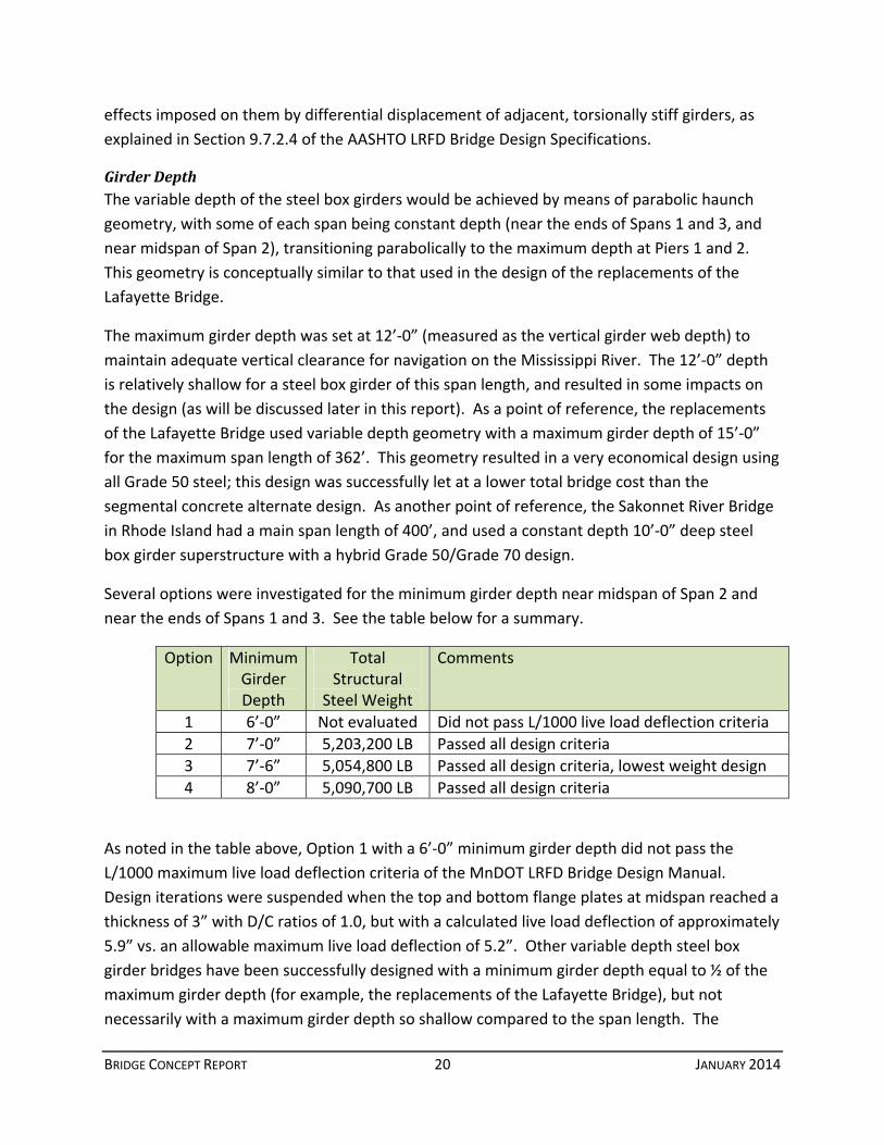
Several options were investigated for the minimum girder depth near midspan of Span 2 and
near the ends of Spans 1 and 3. See the table below for a summary.
Option Minimum Girder Depth
Total Structural
Steel Weight
Comments
1 6’‐0” Not evaluated Did not pass L/1000 live load deflection criteria
2 7’‐0” 5,203,200 LB Passed all design criteria
3 7’‐6” 5,054,800 LB Passed all design criteria, lowest weight design
4 8’‐0” 5,090,700 LB Passed all design criteria
As noted in the table above, Option 1 with a 6’‐0” minimum girder depth did not pass the
L/1000 maximum live load deflection criteria of the MnDOT LRFD Bridge Design Manual.
Design iterations were suspended when the top and bottom flange plates at midspan reached a
thickness of 3” with D/C ratios of 1.0, but with a calculated live load deflection of approximately
5.9” vs. an allowable maximum live load deflection of 5.2”. Other variable depth steel box
girder bridges have been successfully designed with a minimum girder depth equal to ½ of the
maximum girder depth (for example, the replacements of the Lafayette Bridge), but not
necessarily with a maximum girder depth so shallow compared to the span length. The
BRIDGE CONCEPT REPORT 21 JANUARY 2014
span/depth ratio of the steel box girder considered in this study was high enough to necessitate
the likely use of Grade 70 steel, and Grade 70 designs can be controlled by live load deflection
criteria much more so than typical Grade 50 designs.
By increasing the minimum girder depth, particularly at midspan of Span 2, the other girder
depth options were able to successfully achieve the required live load deflection limits. Of
these three options, Option 3 with a 7’‐6” minimum girder depth proved to be the most
economical. The supplemental web depth study is provided in Appendix H.
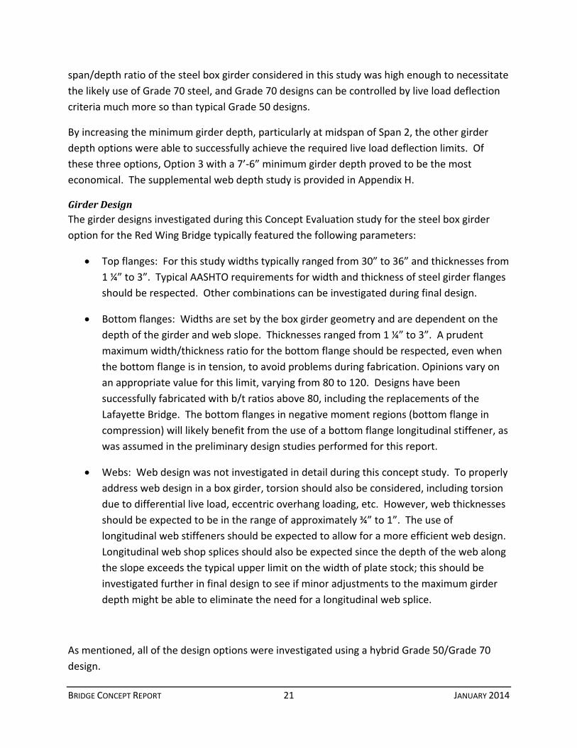
GirderDesignThe girder designs investigated during this Concept Evaluation study for the steel box girder
option for the Red Wing Bridge typically featured the following parameters:
Top flanges: For this study widths typically ranged from 30” to 36” and thicknesses from
1 ¼” to 3”. Typical AASHTO requirements for width and thickness of steel girder flanges
should be respected. Other combinations can be investigated during final design.
Bottom flanges: Widths are set by the box girder geometry and are dependent on the
depth of the girder and web slope. Thicknesses ranged from 1 ¼” to 3”. A prudent
maximum width/thickness ratio for the bottom flange should be respected, even when
the bottom flange is in tension, to avoid problems during fabrication. Opinions vary on
an appropriate value for this limit, varying from 80 to 120. Designs have been
successfully fabricated with b/t ratios above 80, including the replacements of the
Lafayette Bridge. The bottom flanges in negative moment regions (bottom flange in
compression) will likely benefit from the use of a bottom flange longitudinal stiffener, as
was assumed in the preliminary design studies performed for this report.
Webs: Web design was not investigated in detail during this concept study. To properly
address web design in a box girder, torsion should also be considered, including torsion
due to differential live load, eccentric overhang loading, etc. However, web thicknesses
should be expected to be in the range of approximately ¾” to 1”. The use of
longitudinal web stiffeners should be expected to allow for a more efficient web design.
Longitudinal web shop splices should also be expected since the depth of the web along
the slope exceeds the typical upper limit on the width of plate stock; this should be
investigated further in final design to see if minor adjustments to the maximum girder
depth might be able to eliminate the need for a longitudinal web splice.
As mentioned, all of the design options were investigated using a hybrid Grade 50/Grade 70
design.
BRIDGE CONCEPT REPORT 22 JANUARY 2014
Typically it is most economical to limit the thickness of Grade 70 flanges to 2” or less, which
allows for more competition among steel mills which roll Grade 70 steel plate. During final
design, further study using more refined analysis methods would be undertaken to optimize the
flange thicknesses to achieve a design with any Grade 70 flanges set at 2” thickness or less.
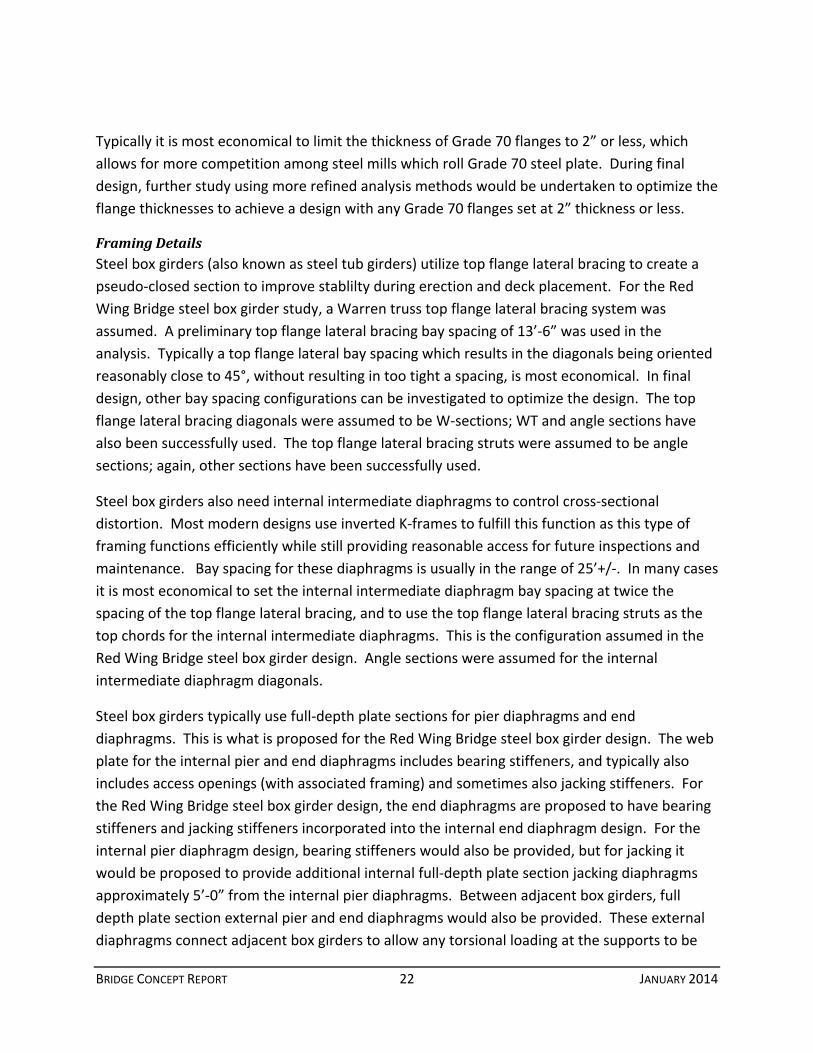
FramingDetailsSteel box girders (also known as steel tub girders) utilize top flange lateral bracing to create a
pseudo‐closed section to improve stablilty during erection and deck placement. For the Red
Wing Bridge steel box girder study, a Warren truss top flange lateral bracing system was
assumed. A preliminary top flange lateral bracing bay spacing of 13’‐6” was used in the
analysis. Typically a top flange lateral bay spacing which results in the diagonals being oriented
reasonably close to 45°, without resulting in too tight a spacing, is most economical. In final
design, other bay spacing configurations can be investigated to optimize the design. The top
flange lateral bracing diagonals were assumed to be W‐sections; WT and angle sections have
also been successfully used. The top flange lateral bracing struts were assumed to be angle
sections; again, other sections have been successfully used.
Steel box girders also need internal intermediate diaphragms to control cross‐sectional
distortion. Most modern designs use inverted K‐frames to fulfill this function as this type of
framing functions efficiently while still providing reasonable access for future inspections and
maintenance. Bay spacing for these diaphragms is usually in the range of 25’+/‐. In many cases
it is most economical to set the internal intermediate diaphragm bay spacing at twice the
spacing of the top flange lateral bracing, and to use the top flange lateral bracing struts as the
top chords for the internal intermediate diaphragms. This is the configuration assumed in the
Red Wing Bridge steel box girder design. Angle sections were assumed for the internal
intermediate diaphragm diagonals.
Steel box girders typically use full‐depth plate sections for pier diaphragms and end
diaphragms. This is what is proposed for the Red Wing Bridge steel box girder design. The web
plate for the internal pier and end diaphragms includes bearing stiffeners, and typically also
includes access openings (with associated framing) and sometimes also jacking stiffeners. For
the Red Wing Bridge steel box girder design, the end diaphragms are proposed to have bearing
stiffeners and jacking stiffeners incorporated into the internal end diaphragm design. For the
internal pier diaphragm design, bearing stiffeners would also be provided, but for jacking it
would be proposed to provide additional internal full‐depth plate section jacking diaphragms
approximately 5’‐0” from the internal pier diaphragms. Between adjacent box girders, full
depth plate section external pier and end diaphragms would also be provided. These external
diaphragms connect adjacent box girders to allow any torsional loading at the supports to be

BRIDGE CONCEPT REPORT 23 JANUARY 2014
carried via force‐couple action between adjacent box girders. This allows for the use of single
bearings under each box girder and provides a very efficient design.
External intermediate diaphragms (external diaphragms between adjacent box girders within
the length of each span) are not proposed for the Red Wing Bridge steel box girder option.
Typically external intermediate diaphragms are needed only in curved steel box girder bridges
(typically only in bridges with longer spans or severe curvature), to control relative torsional
displacement between girders. Since the Red Wing Bridge is straight, external intermediate
diaphragms are not required.
JointsandBearingsFor the steel box girder alternate for the Red Wing Bridge, bearing fixity was assumed at Pier 2
and at Pier 6 (for the five‐span north approach option, or Pier 5 if a four‐span north approach
option is chosen). With these fixities, the anticipated movement demands (assuming a 150°
design temperature range) are as follows:
South Abutment – 648’ expansion length – approx. 8” movement demand – provide a
Type 9 modular joint
Pier 3 – 586’ to 641’ expansion length* ‐ approx. 7” to 8” movement demand – provide
a Type 9 modular joint
North Abutment – 335’ to 390’ expansion length* ‐ approximately 4” to 5” movement
demand – assume a Type 6 modular joint (a Type 4 strip seal may be possible)
*Expansion length depends on span arrangement chosen for the north approach spans unit.
A single bearing is proposed for each box girder at each support. Through previous design
experience a design using external pier and end diaphragms and a single bearing per girder has
proven better than using two bearings per girder. Using two bearings, and omitting external
pier and end diaphragms, requires the torsion in each girder to be reacted by means of a short‐
distance force‐couple between the two bearings; this can lead to uplift in some cases. Also,
there have been issues associated with fit‐up and proper bearing seating when dual bearings
have been used. Single bearing designs function more efficiently and avoid these fit‐up issues.
The single bearings at Piers 1 and 2 for the steel box girder unit would be subject to high axial
loads and rotations; high‐load multi‐rotational bearings such as disc or pot bearings would be
appropriate. The bearings at Pier 3 and the South Abutment would be subject to much lower
loads; elastomeric bearing pads, disc bearings, or pot bearings could be used. For the other
substructures, standard elastomeric bearing pads could be used .
BRIDGE CONCEPT REPORT 24 JANUARY 2014
It should be noted that due to the poor span balance of the three‐span steel box girder unit
(with short end spans), the bearing reactions at Pier 3 and the South Abutment are fairly low.
While no uplift was noted during the preliminary design, this should be investigated in the final
design. If the final design results in uplift, measures such as ballasting or providing bearing tie‐
downs may be required.
FabricationThe fabrication of steel box girders, particularly variable depth steel box girders with sloped
webs, is more complicated than the fabrication of steel plate girders. However, the steel
fabrication industry is well‐equipped and experienced in handling the challenges of fabricating
steel box girders. MnDOT has recently overseen the fabrication of a significant number of steel
box girders for the replacements of the Lafayette Bridge, and other steel box girder projects in
the region have shown that regional fabricators can produce these girders successfully.
Effective design can also make the fabrication of steel box girders much easier and more
economical. Recent steel box girder design experience is helpful, along with reference to
guideline documents such as the NSBA’s Practical Steel Tub Girder Design manual, and the
guideline documents published by the AASTHO/NSBA Steel Bridge Collaboration.
GradeandProfileThe steel box girder option is the midrange option of the three concepts being reviewed in
terms of minimizing superstructure depth, at a maximum depth of 12’ over the piers it is
shallower than the concrete segmental box girder option but still deeper than the tied arch
option.
SpanArrangement
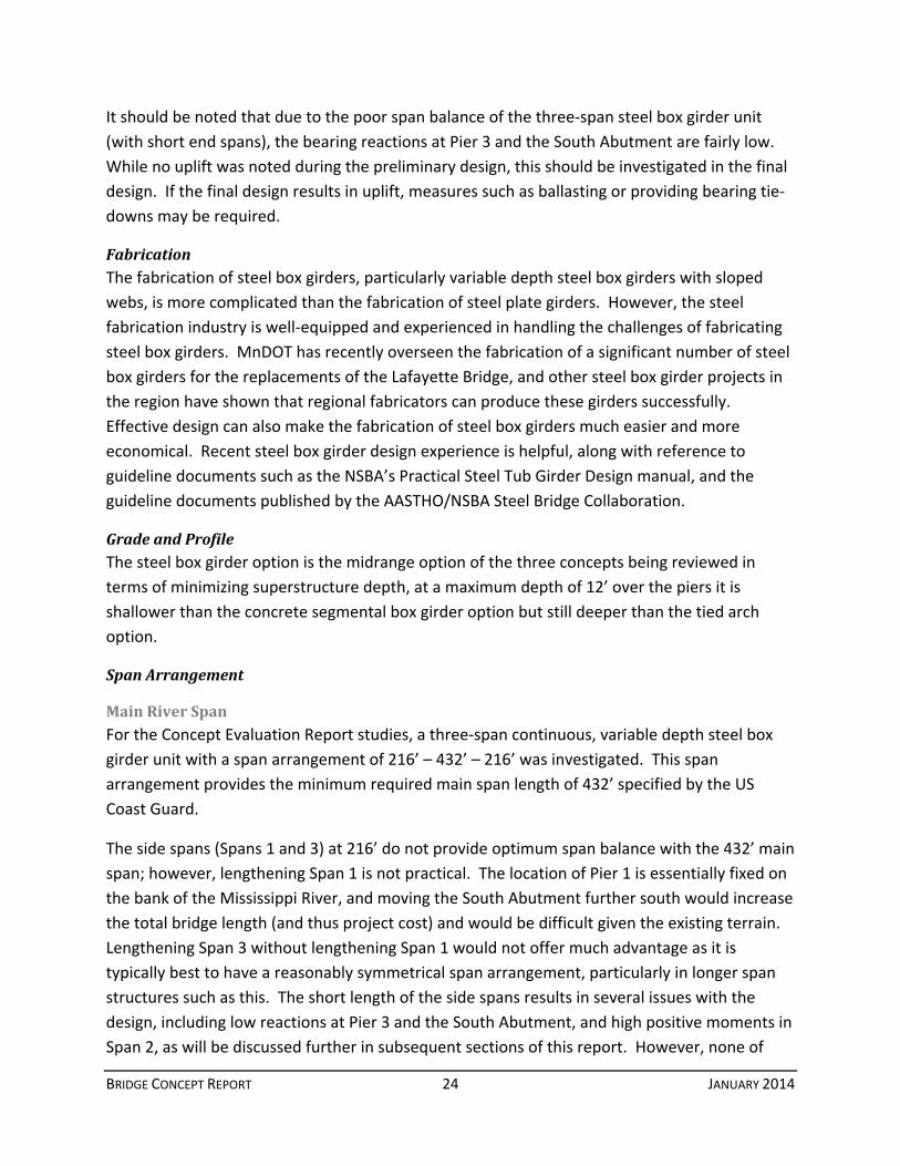
MainRiverSpanFor the Concept Evaluation Report studies, a three‐span continuous, variable depth steel box
girder unit with a span arrangement of 216’ – 432’ – 216’ was investigated. This span
arrangement provides the minimum required main span length of 432’ specified by the US
Coast Guard.
The side spans (Spans 1 and 3) at 216’ do not provide optimum span balance with the 432’ main
span; however, lengthening Span 1 is not practical. The location of Pier 1 is essentially fixed on
the bank of the Mississippi River, and moving the South Abutment further south would increase
the total bridge length (and thus project cost) and would be difficult given the existing terrain.
Lengthening Span 3 without lengthening Span 1 would not offer much advantage as it is
typically best to have a reasonably symmetrical span arrangement, particularly in longer span
structures such as this. The short length of the side spans results in several issues with the
design, including low reactions at Pier 3 and the South Abutment, and high positive moments in
Span 2, as will be discussed further in subsequent sections of this report. However, none of

BRIDGE CONCEPT REPORT 25 JANUARY 2014
these issues represent a fatal flaw, and the bridge can be designed successfully with this span
arrangement.
Consideration was given to lengthening Span 2 if it would result in improvement to the overall
design. However, given the limits to the superstructure depth, lengthening Span 2 would be
challenging and offer no advantages. The current length of Span 2 at 432’ is near the practical
limits for the multiple steel box girder cross‐section investigated in this study given the
limitation of a 12’ maximum girder depth. Increasing the length of Span 2 would likely result in
an uneconomical design.
ApproachSpansA four‐span continuous steel plate girder unit (165’ – 215’‐6” – 215’‐6” – 165’) is one of two
configurations proposed for the north approach. This arrangement is well within the
economical range of constant depth steel plate girder design. This design eliminates one pier as
compared to the prestressed beam approach of the segmental concrete box concept.
A constant depth steel plate girder design should prove to be very economical. With proper
care taken in the design and detailing, this should also provide a relatively clean and simple
appearance.
The second option involves utilizing prestressed beams starting with span 4 and continuing
north to the north abutment. The spans would be identical (152’ – 152’ – 152’ – 152’ – 152’)
thus providing some efficiency in design and construction. As mentioned earlier, this would
require an additional pier compared to the steel plate girder arrangement.
While it is less aesthetically pleasing to have different span materials in a single structure, the
prestressed beam spans would be obscured by foliage for half of the year.
Constructability
ErectionMethodsErection of steel box girder bridges is relatively straightforward and is similar to the erection of
steel plate girder bridges. At the longer span lengths featured in the Red Wing Bridge steel box
girder design, some additional issues exist, but these have been successfully addressed on
several previous projects.
The following field sections would be proposed. All dimensions are approximate and would be
refined in final design.
1. Span 1 Drop‐in Section: Approximately 132’ (FS 1)
2. Pier 1 Pier Section: Approximately 134’ (FS 2)

BRIDGE CONCEPT REPORT 26 JANUARY 2014
3. Span 2, Pier 1 Cantilever Section: Approximately 116’ (FS 3)
4. Span 2 Drop‐in Section: Approximately 100’ (FS 4)
5. Span 2, Pier 2 Cantilever Section: Approximately 116’ (FS 5)
6. Pier 2 Pier Section: Approximately 134’ (FS 6)
7. Span 3 Drop‐in Section: Approximately 132’ (FS 7)
At the Red Wing Bridge site, the following conceptual erection scheme would be possible:
1. Erect FS 2 by cranes on land and/or barge, with a temporary support on land or using a
pier bracket
2. Erect FS 1 by cranes on land
3. Erect FS 6 by cranes on land and/or barge, with a temporary support near the north
shore of the Mississippi River
4. Erect FS 7 by cranes on land
5. Erect FS 3 by cranes on barge
6. Erect FS 5 by cranes on barge
7. Erect FS 4 by cranes on barge or by strand jacking from the previously erected cantilever
sections
This erection sequence requires only a reasonable amount of temporary shoring. Once FS 1
and 2 are erected, they are stable and temporary shoring can be removed; the erection of FS 6
and 7 would be similar. Temporary tie‐downs at Pier 3 and the South Abutment may be
required, but such provisions are reasonable and expected in longer span girder bridge
construction.
The field section lengths were chosen to keep pick weights reasonable and to facilitate
transportation by either truck or barge. The girder sections are fairly wide and tall, so truck
transport may be subject to oversize load permits and the route from the fabrication shop to
the bridge site would need to be investigated for any pinch points. Barge transportation of
girder sections should be relatively easy since the bridge site spans the Mississippi River, which
is fully navigable for barge traffic.
Each girder line can be erected independently, without the need for temporary cross‐frames
between girders. This is due to the inherently stable nature of steel box girders when they are
BRIDGE CONCEPT REPORT 27 JANUARY 2014
provided with a properly designed top flange lateral bracing system. The girders should be able
to cantilever out the distances suggested by the above‐listed field section lengths. In final
design it would be advisable to perform a cursory erection analysis to ensure that the girders
are sufficiently sized to sustain loading in this cantilever condition.
SchedulingandStagingThis alternate could be constructed without placing falsework in the main Mississippi River
channel by erecting field segments from cranes on land and on barges. This may require
backstays or other means to reduce the forces in the cantilevered section and should be
investigated further during preliminary design. Compared to the other alternates, the
continuous steel box girder alternate would require the least specialized equipment and
erection procedures to construct.
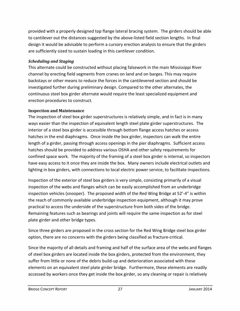
InspectionandMaintenanceThe inspection of steel box girder superstructures is relatively simple, and in fact is in many
ways easier than the inspection of equivalent length steel plate girder superstructures. The
interior of a steel box girder is accessible through bottom flange access hatches or access
hatches in the end diaphragms. Once inside the box girder, inspectors can walk the entire
length of a girder, passing through access openings in the pier diaphragms. Sufficient access
hatches should be provided to address various OSHA and other safety requirements for
confined space work. The majority of the framing of a steel box girder is internal, so inspectors
have easy access to it once they are inside the box. Many owners include electrical outlets and
lighting in box girders, with connections to local electric power service, to facilitate inspections.
Inspection of the exterior of steel box girders is very simple, consisting primarily of a visual
inspection of the webs and flanges which can be easily accomplished from an underbridge
inspection vehicles (snooper). The proposed width of the Red Wing Bridge at 52’‐4” is within
the reach of commonly available underbridge inspection equipment, although it may prove
practical to access the underside of the superstructure from both sides of the bridge.
Remaining features such as bearings and joints will require the same inspection as for steel
plate girder and other bridge types.
Since three girders are proposed in the cross section for the Red Wing Bridge steel box girder
option, there are no concerns with the girders being classified as fracture‐critical.
Since the majority of all details and framing and half of the surface area of the webs and flanges
of steel box girders are located inside the box girders, protected from the environment, they
suffer from little or none of the debris build‐up and deterioration associated with these
elements on an equivalent steel plate girder bridge. Furthermore, these elements are readily
accessed by workers once they get inside the box girder, so any cleaning or repair is relatively

BRIDGE CONCEPT REPORT 28 JANUARY 2014
easy. Routine maintenance of a steel box girder bridge should consist primarily of periodic
cleaning and painting of the steel, with these efforts being more limited (less frequently
required) for interior surfaces and components. Remaining features such as bearings and joints
will require the same maintenance as for steel plate girder and other bridge types.
Costs
ConstructionThe preliminary estimated construction cost of the steel box girder superstructure is as follows:
Concept Description Estimate (2018 $’s)
Main Unit with Prestressed Beam Approaches $61.4 Million
The estimate was based on typical MnDOT unit cost data when applicable, and reasonable
extrapolations for elements unique to a steel box girder design. The bid tabulations for the
recently let replacements of the Lafayette Bridge, particularly those for structural steel, were
also considered. An escalation factor of 1.33 provided by MnDOT was used to adjust 2012
dollars to 2018 dollars. Unit costs from 2012 were used since more current 2013 costs were
unavailable at the time of this writing. The estimate includes a 10% adjustment for
miscellaneous elements such as wing walls, mask walls, slope paving, lighting, signage, and
drainage systems that are not included in the cost of other items as well as a 20% adjustment
for engineering and administration. A 10% contingency is applied to the entire estimate to
account for unforeseen project issues and fluctuations in construction costs and materials.
LifeCycleThe life cycle costs of a steel box girder superstructure should be expected to be less than those
of an equivalent steel plate girder design. As mentioned previously, most of the steel details
and framing are located inside the box girders, protected from the environment. As a result, a
steel box girder bridge is typically subject to significantly less long term deterioration than an
equivalent steel plate girder bridge, leading to significantly reduced long term repair,
maintenance, and painting costs.
RisksThe main risks associated with a steel box girder alternate for the Red Wing Bridge concern
pricing, particularly of the structural steel. Over the past decade, structural steel prices have
demonstrated some volatility in response to fluctuations in demand in both the US and global
steel markets. Although this is a concern with any construction material, the more limited
industry capacity of steel mills and fabricators may have some tendency to exacerbate this
problem. Also, steel delivery time constraints have been an issue on recent MnDOT projects.

BRIDGE CONCEPT REPORT 29 JANUARY 2014
There are few if any significant design or construction risks associated with the steel box girder
alternate for the Red Wing Bridge. Steel box girder designs of this type have been successfully
completed and built many times. The main span length of 432’ is far from the upper limit of
this general structure type. The Red Wing site has good access for material delivery, especially
from the river, and for staging, erection, and other construction activities.
AdvantagesandDisadvantages
Advantages Disadvantages Conventional erection and
construction Potential volatility of steel prices
Relatively straight forward inspection Requires periodic painting
Modest profile impacts (particularly as compared to concrete segmental)
Construction cost is nearly as low as the Concrete Segmental (within 2%)
BRIDGE CO
Alterna
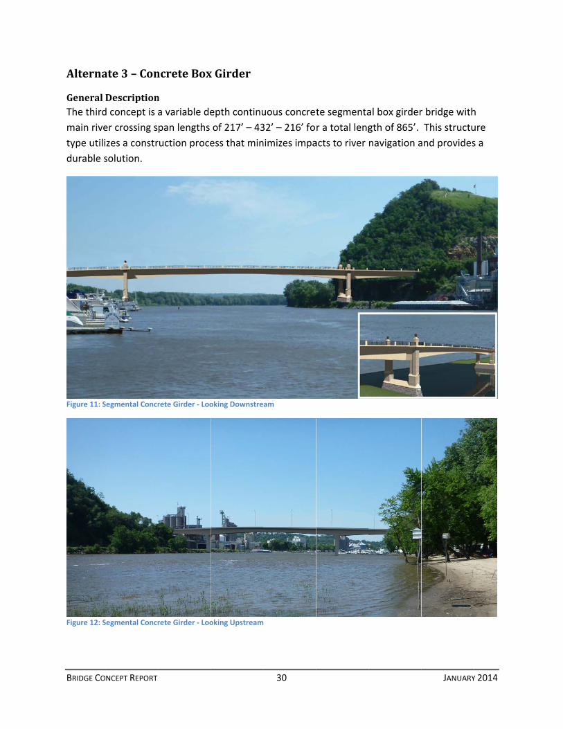
GeneralThe third
main rive
type utili
durable s
Figure 11: S
Figure 12: S
NCEPT REPORT
ate3–Con
Descriptiond concept is
er crossing s
zes a constr
solution.
Segmental Concr
Segmental Concr
ncreteBox
na variable de
pan lengths
ruction proce
rete Girder ‐ Loo
rete Girder ‐ Loo
xGirder
epth continu
of 217’ – 43
ess that min
oking Downstre
oking Upstream
30
uous concret
32’ – 216’ fo
nimizes impa
am
te segmenta
r a total leng
acts to river
al box girder
gth of 865’.
navigation a
JANUARY
r bridge with
This structu
and provides
Y 2014
h
ure
s a

BRIDGE CONCEPT REPORT 31 JANUARY 2014
Maintaining river traffic through construction is a primary requirement of the US Coast Guard.
Maintenance of the navigational channel throughout construction is achieved through the use
of built‐from‐above techniques. The anticipated construction approach for the concrete
segmental bridge is the Cast‐in‐Place Balanced Cantilever construction method and is a solution
for this constraint.
Box girder structures use a combination of mild steel reinforcement in conjunction with high
strength post‐tensioning steel tendons to resist tension and shear forces. The riding surface of
the bridge is post‐tensioned in two directions to minimize concrete stresses and provide a
highly durable solution.
Segmental concrete box girder bridges have been constructed throughout the United States.
Several have been constructed in Minnesota including the Crosstown Project, the I‐494 Wakota
Project, the Dresbach Bridge on I‐90, and the I‐35W Bridge Replacement in Minneapolis.
JointsandBearingsFor the segmental concrete box girder alternate for the Red Wing Bridge, expansion joint
devices are required at the South Abutment, Pier 3 and the North Abutment. To estimate the
magnitude of movement, bearing fixity was assumed at center of Span 2 and at Pier 6 (for the
five‐span north approach option, or Pier 5 if a four‐span north approach option is chosen).
With these fixities, the anticipated movement demands (assuming a 150° design temperature
range) are as follows:
South Abutment – 432’ expansion length – approx. 11” movement demand – provide a
Type 12 modular joint
Pier 3 – 802’ to 857’ expansion length* ‐ approx. 16” to 17” movement demand –
provide a Type 18 modular joint
North Abutment – 335’ to 390’ expansion length* ‐ approximately 4” to 5” movement
demand – assume a Type 6 modular joint (a Type 4 strip seal may be possible)
*Expansion length depends on span arrangement chosen for the north approach spans unit.
The segmental concrete box girder unit utilizes a pair of bearings at each end of the unit to
provide support. At intermediate pier locations within that unit, the superstructure and
substructure will be locked together without requiring use of bearing devices. The bearings
beneath the concrete box at Pier 3 and the South Abutment would be subject to loads likely
requiring disc bearings or pot bearings. For other substructure locations, standard elastomeric
bearing pads could be used.

BRIDGE CONCEPT REPORT 32 JANUARY 2014
Figure 13: Segmental Concrete Box Girder Typical River Crossing Section
Figure 14" Segmental Concrete Box Girder River Spans Elevation View
GradeandProfileAs identified above, the segmental concrete box girder has a maximum depth of 21’ at piers 1
and 2 which is the deepest structure of the three concepts being reviewed. The river
navigational channel vertical clearance requirements combined with the need to maintain a
certain vertical alignment significantly limits the design option possibilities with segmental
concrete box girder concept. The study reviewed profile solutions to allow consideration of the
concrete box girder solutions as follows:
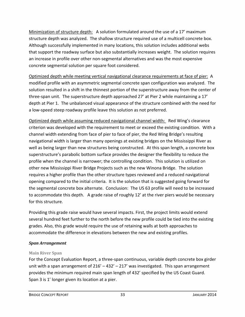
BRIDGE CONCEPT REPORT 33 JANUARY 2014
Minimization of structure depth: A solution formulated around the use of a 17’ maximum
structure depth was analyzed. The shallow structure required use of a multicell concrete box.
Although successfully implemented in many locations, this solution includes additional webs
that support the roadway surface but also substantially increases weight. The solution requires
an increase in profile over other non‐segmental alternatives and was the most expensive
concrete segmental solution per square foot considered.
Optimized depth while meeting vertical navigational clearance requirements at face of pier: A
modified profile with an asymmetric segmental concrete span configuration was analyzed. The
solution resulted in a shift in the thinnest portion of the superstructure away from the center of
three‐span unit. The superstructure depth approached 27’ at Pier 2 while maintaining a 17’
depth at Pier 1. The unbalanced visual appearance of the structure combined with the need for
a low‐speed steep roadway profile leave this solution as not preferred.
Optimized depth while assuming reduced navigational channel width: Red Wing’s clearance
criterion was developed with the requirement to meet or exceed the existing condition. With a
channel width extending from face of pier to face of pier, the Red Wing Bridge’s resulting
navigational width is larger than many openings at existing bridges on the Mississippi River as
well as being larger than new structures being constructed. At this span length, a concrete box
superstructure’s parabolic bottom surface provides the designer the flexibility to reduce the
profile when the channel is narrower; the controlling condition. This solution is utilized on
other new Mississippi River Bridge Projects such as the new Winona Bridge. The solution
requires a higher profile than the other structure types reviewed and a reduced navigational
opening compared to the initial criteria. It is the solution that is suggested going forward for
the segmental concrete box alternate. Conclusion: The US 63 profile will need to be increased
to accommodate this depth. A grade raise of roughly 12’ at the river piers would be necessary
for this structure.
Providing this grade raise would have several impacts. First, the project limits would extend
several hundred feet further to the north before the new profile could be tied into the existing
grades. Also, this grade would require the use of retaining walls at both approaches to
accommodate the difference in elevations between the new and existing profiles.
SpanArrangement
MainRiverSpanFor the Concept Evaluation Report, a three‐span continuous, variable depth concrete box girder
unit with a span arrangement of 216’ – 432’ – 217’ was investigated. This span arrangement
provides the minimum required main span length of 432’ specified by the US Coast Guard.
Span 3 is 1’ longer given its location at a pier.
BRIDGE CONCEPT REPORT 34 JANUARY 2014
The side spans (Spans 1 and 3) at 216’ and 217’, respectively, do not provide optimum span
balance with the 432’ main span. This analysis reviewed lengthening Span 1 but concluded it is
not practical. The location of Pier 1 is essentially fixed on the bank of the Mississippi River, and
moving the South Abutment further south would increase the total bridge length (and thus
project cost) and would be difficult given the existing terrain. Lengthening Span 3 without
lengthening Span 1 would not offer an advantage as it is best to have a reasonably symmetrical
span arrangement. The short length of the side spans impacts the design in several ways
including the need to evaluate the possibility of uplift at the unit’s end supports at Pier 3 and
the South Abutment as well as designing for higher stress demands in Span 2. These issues do
not represent a fatal flaw. The bridge can be designed economically with this span
arrangement.
We anticipate the structure will utilize the cast‐in‐place construction method with form
travelers. Experience on other projects indicates there may not be enough concrete segments
to make the creation of a casting yard for precast segments economical.
ApproachSpansThe north approach span configuration involves utilizing 82MW prestressed beams starting
with span 4 and continuing north to the north abutment. The suggested five spans would be
identical in length (152’ – 152’ – 152’ – 152’ – 152’) providing some efficiency in design and
construction.
While some may feel it is less aesthetically pleasing to have different span types in a single
structure, the prestressed beam spans would be obscured by foliage for part of the year.
ConstructabilityWe consider the cast‐in‐place balanced cantilever construction method as the best construction
technique for the spans across the river. The balanced cantilever construction concept was
originally developed as a means for elimination of falsework. This construction method allows
the contractor to maintain a channel opening for barge traffic during construction. Efficiency of
the balanced cantilever construction method improves when the shape of the cross‐section of
the bridge is consistent, uniform, and allows a reusable forming system. The proposed bridge’s
constant deck width and straight alignment are well suited for use of this construction method.
The bridge site has few constraints in accessing the site. Either through the use of barges or by
accessing the site from US 63, minimal limitations to the contractor are anticipated.
Each box girder segment is approximately 16’ long. The pier table, cast on top of each pier, will
be non‐symmetrical, having an 18’ cantilever at one side of the pier and a 26’ cantilever on the
other side. This stagger will reduce the out‐of‐balance forces acting on the column and footing
during construction to approximately 8’ of bridge length (half a segment).

BRIDGE CONCEPT REPORT 35 JANUARY 2014
The box girder segments will be cast in place with a form traveler using the balanced‐cantilever
construction method. Although transportation of precast segments to the site is possible, the
capital investment required when starting up a precasting facility is significant. Even though
the costs of a form traveler is greater than forms in the precast yard, the associated land and
facility costs of the precasting yard are not equaled. A significant advantage of any cast‐in‐
place method of construction when compared to a precast method is that there is almost no
limitation to the size of cross‐section. Although both the size and cost of the form traveler
increases with size of section when casting‐in‐place, the impact on precasting costs is the same
or greater due to the impact on transportation costs. Finally, precast erection of segments will
provide a greater restriction on channel navigation than would be expected with the cast‐in‐
place construction method. Positioning of construction barges would require coordination with
movements of transiting cargo barges. The relatively short length of the balanced cantilever
segmental superstructure bridge at Red Wing justifies the assertion that the cast‐in‐place
method of construction should be utilized instead of the precast method. For this structure, w
e do not believe a precast method of construction is economically competitive. One should
note that the use of the cast‐in‐place on falsework method of construction will be required for
the last few feet of superstructure adjacent to each expansion joint.
After casting a pair of segments, a number of cantilever tendons (at least two but as many as
four) will be stressed before moving the form travelers to the tip of the completed segments.
The cantilever tendons consist of twenty‐one 0.6‐inch low relaxation strands. After completing
a set of cantilevers, an approximately eight foot long closure pour is constructed at mid span.
Longitudinal tendons will be installed at the top and bottom of the section along the bridge
near midspan.
The deck of each box girder segment is transversely post‐tensioned to provide two‐way slab
compression. Minimizing the possibility of the concrete deck experiencing either longitudinal
or transverse tension resulting in cracks provides an assurance of long‐term durability.
InspectionandMaintenanceA segmental concrete bridge is an attractive solution from an inspection and maintenance
perspective. The structure is designed to have components in compression due to post‐
tensioning, generally in both longitudinal and transverse directions. This significantly reduces
maintenance problems caused in non‐prestressed concrete by cracking and water penetration
when members are under tension.
Bridge inspections will monitor the bridge from three perspectives:
1. Exterior access to the outside of the concrete boxes would be obtained by using an
Under Bridge Inspection Vehicle (UBIV). With no superstructure members above the
BRIDGE CONCEPT REPORT 36 JANUARY 2014
deck, the underside of this alternate would be easier to inspect with an UBIV than the
Tied Arch.
2. The concrete box structure type requires that the inside of the concrete boxes be
inspected. Access to the inside of the boxes would be gained through secured access
hatches located at the ends of the concrete segmental unit. Lighting and electrical
outlets would be provided inside the concrete box at regular intervals along the bridge
to facilitate inspection. The segmental box girder superstructure provides internal
headroom of greater than 8’‐0”. Diaphragm access openings will be a minimum of 36”
wide and 48” tall and bottom flange access openings of 32” x 42” width.
3. Finally, miscellaneous bridge components such as expansion joints and bearings require
up close inspection. Access to expansion joint devices at deck level and from beneath is
crucial. Consideration of jack placement when detailing piers/pedestals is required
during the design phase.
Costs
ConstructionThe preliminary estimated Construction cost of the segmental concrete box girder
superstructure is as follows:
Concept Description Estimate (2018 $’s)
Main Unit with Prestressed Beam Approaches $60.2 Million
The estimate was based on typical MnDOT unit cost data when applicable, and reasonable
extrapolations for elements unique to a segmental concrete box girder design. The bid
tabulations for the recently let replacement of the Dresbach Bridge were also considered. An
escalation factor of 1.33 provided by MnDOT was used to adjust 2012 dollars to 2018 dollars.
Unit costs from 2012 were used since more current 2013 costs were unavailable at the time of
this writing. The estimate includes a 10% adjustment for miscellaneous elements such as wing
walls, mask walls, slope paving, lighting, signage, and drainage systems that are not included in
the cost of other items as well as a 20% adjustment for engineering and administration. A 10%
contingency is applied to the entire estimate to account for unforeseen project issues and
fluctuations in construction costs and materials.
LifeCycleFuture maintenance for the concrete segmental box alternate includes periodic inspections and
wearing surface application. Life cycle costs for this concept are typically less than the other
two concepts because it does not need to be repainted.

BRIDGE CONCEPT REPORT 37 JANUARY 2014
RisksRisk associated with this structure type will involve fluctuations in construction materials.
Because this concept utilizes concrete as its primary structural material, any rise in unit cost will
have a large impact on the overall construction cost. Fluctuations in concrete material costs
have not historically been as volatile as steel.
Availability of contractors should not be problematic since the segmental concrete box has
been successfully utilized by several of the larger local bridge contractors.
Advantages&DisadvantagesCompared to the steel alternatives considered for the Red Wing Bridge, the cast‐in‐place
concrete segmental alternate offers the following advantages and disadvantages (continued on
next page).
Advantages Disadvantages Complex erection is not required Requires substantial profile increase
Relatively straight forward inspection Greatest visual impacts from deep section
Low long term maintenance costs Longest distance at maximum grade
Lowest construction cost
SummaryIt is the opinion of the authors that given the detailed comparative information provided herein
and summarized in matrix form on the following page, the recommended alternative is the
steel box girder. It offers a lower construction cost than the tied arch, the lowest maintenance
cost of either steel option, a shallower profile than the segmental concrete box girder, reduced
approach grades compared to the segmental concrete box girder, and aesthetic qualities that
compliment stakeholder values. In addition, we believe MnDOT will find this alternative to
offer a very competitive bidding environment since there are numerous local contractors with
steel box girder experience.
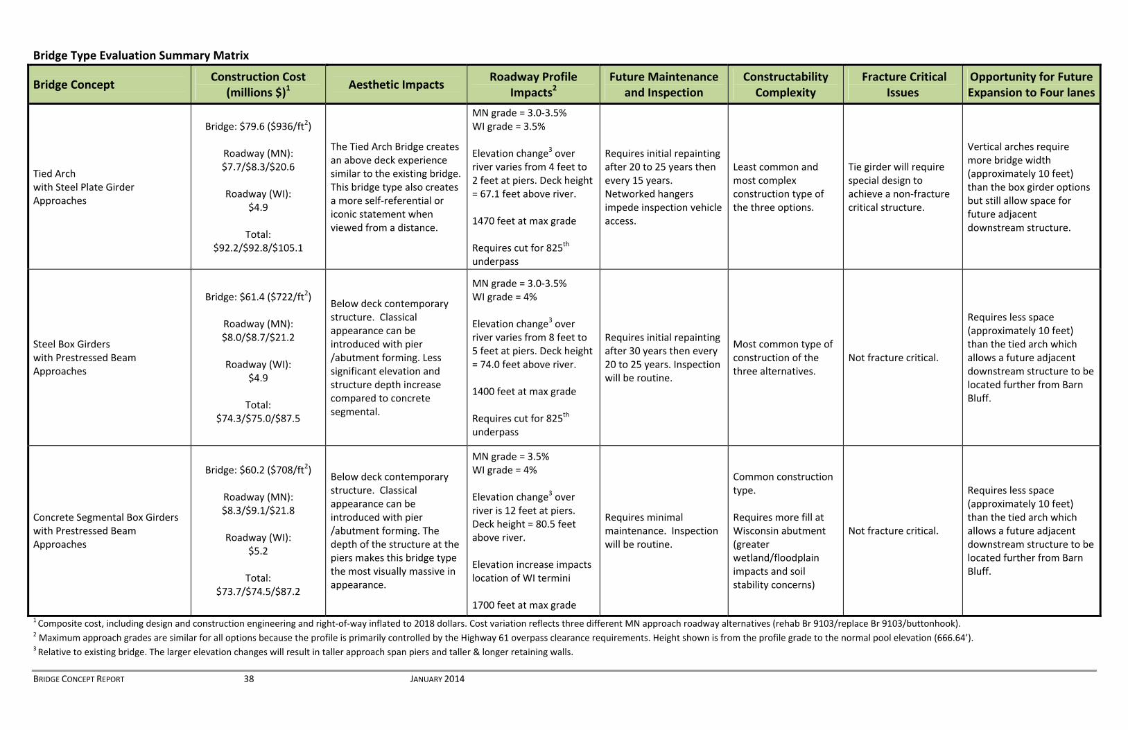
BRIDGE CONCEPT REPORT 38 JANUARY 2014
1 Composite cost, including design and construction engineering and right‐of‐way inflated to 2018 dollars. Cost variation reflects three different MN approach roadway alternatives (rehab Br 9103/replace Br 9103/buttonhook). 2 Maximum approach grades are similar for all options because the profile is primarily controlled by the Highway 61 overpass clearance requirements. Height shown is from the profile grade to the normal pool elevation (666.64’). 3 Relative to existing bridge. The larger elevation changes will result in taller approach span piers and taller & longer retaining walls.
Bridge Type Evaluation Summary Matrix
Bridge Concept Construction Cost
(millions $)1 Aesthetic Impacts
Roadway Profile Impacts2
Future Maintenance and Inspection
Constructability Complexity
Fracture Critical Issues
Opportunity for Future Expansion to Four lanes
Tied Arch with Steel Plate Girder Approaches
Bridge: $79.6 ($936/ft2)
Roadway (MN): $7.7/$8.3/$20.6
Roadway (WI):
$4.9
Total: $92.2/$92.8/$105.1
The Tied Arch Bridge creates an above deck experience similar to the existing bridge. This bridge type also creates a more self‐referential or iconic statement when viewed from a distance.
MN grade = 3.0‐3.5% WI grade = 3.5% Elevation change3 over river varies from 4 feet to 2 feet at piers. Deck height = 67.1 feet above river. 1470 feet at max grade Requires cut for 825th underpass
Requires initial repainting after 20 to 25 years then every 15 years. Networked hangers impede inspection vehicle access.
Least common and most complex construction type of the three options.
Tie girder will require special design to achieve a non‐fracture critical structure.
Vertical arches require more bridge width (approximately 10 feet) than the box girder options but still allow space for future adjacent downstream structure.
Steel Box Girders with Prestressed Beam Approaches
Bridge: $61.4 ($722/ft2)
Roadway (MN): $8.0/$8.7/$21.2
Roadway (WI):
$4.9
Total: $74.3/$75.0/$87.5
Below deck contemporary structure. Classical appearance can be introduced with pier /abutment forming. Less significant elevation and structure depth increase compared to concrete segmental.
MN grade = 3.0‐3.5% WI grade = 4% Elevation change3 over river varies from 8 feet to 5 feet at piers. Deck height = 74.0 feet above river. 1400 feet at max grade Requires cut for 825th underpass
Requires initial repainting after 30 years then every 20 to 25 years. Inspection will be routine.
Most common type of construction of the three alternatives.
Not fracture critical.
Requires less space (approximately 10 feet) than the tied arch which allows a future adjacent downstream structure to be located further from Barn Bluff.
Concrete Segmental Box Girders with Prestressed Beam Approaches
Bridge: $60.2 ($708/ft2)
Roadway (MN): $8.3/$9.1/$21.8
Roadway (WI):
$5.2
Total: $73.7/$74.5/$87.2
Below deck contemporary structure. Classical appearance can be introduced with pier /abutment forming. The depth of the structure at the piers makes this bridge type the most visually massive in appearance.
MN grade = 3.5% WI grade = 4% Elevation change3 over river is 12 feet at piers. Deck height = 80.5 feet above river. Elevation increase impacts location of WI termini 1700 feet at max grade
Requires minimal maintenance. Inspection will be routine.
Common construction type. Requires more fill at Wisconsin abutment (greater wetland/floodplain impacts and soil stability concerns)
Not fracture critical.
Requires less space (approximately 10 feet) than the tied arch which allows a future adjacent downstream structure to be located further from Barn Bluff.

APPENDICESAppendixAConceptProfilesAppendixBBridgeSectionComparisonsAppendixCConceptCostEstimatesAppendixDNewStructureAlternativesMemoAppendixETiedArchDetailsAppendixFU.S.CoastGuardClearanceEnvelopeDocumentsAppendixGVisualConsiderations–Bridge9040NewStructurestypesAppendixHSupplementalWebDepthStudy

AppendixAConceptProfiles

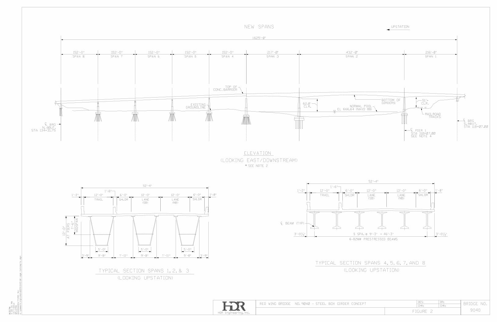
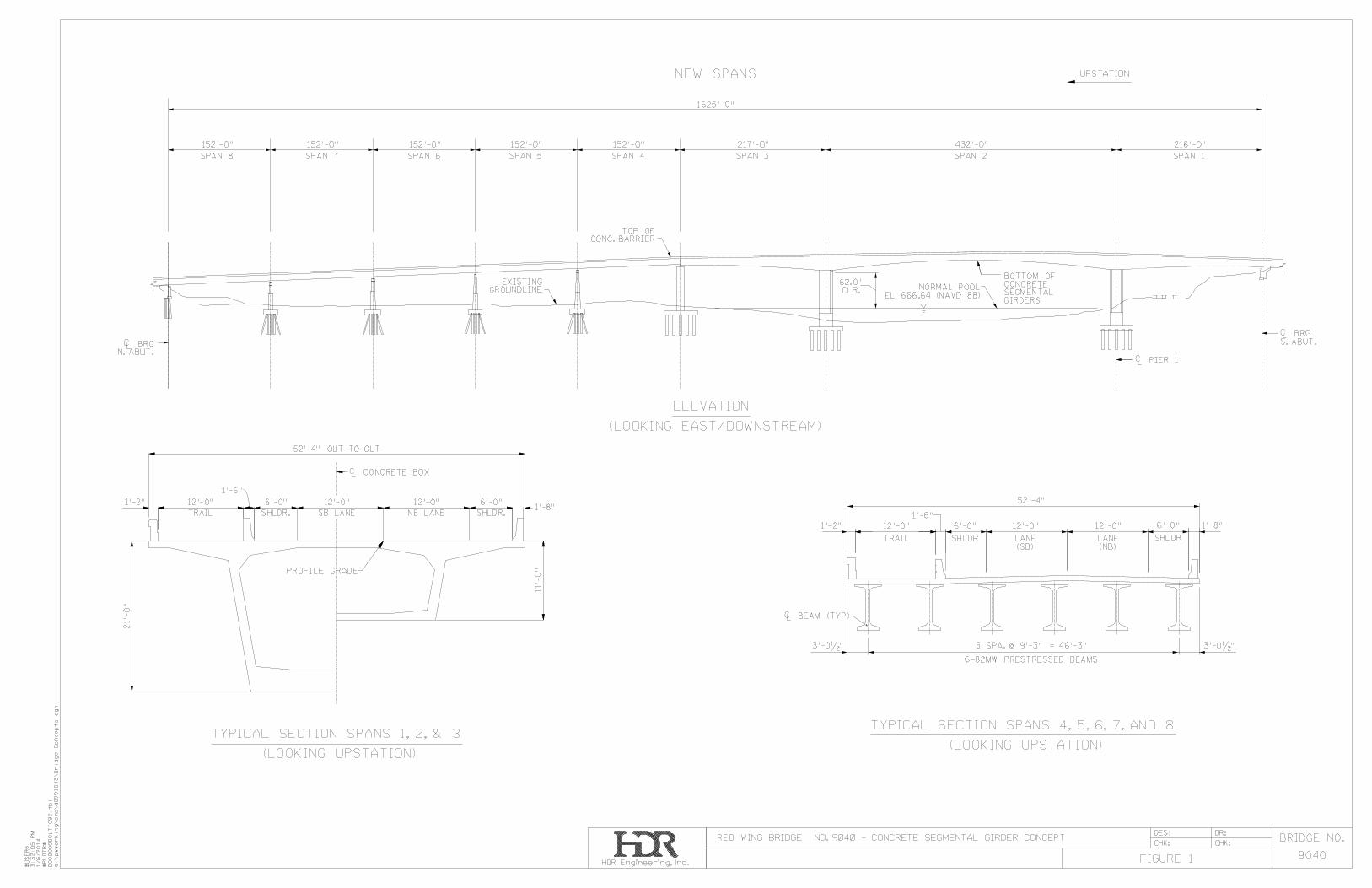
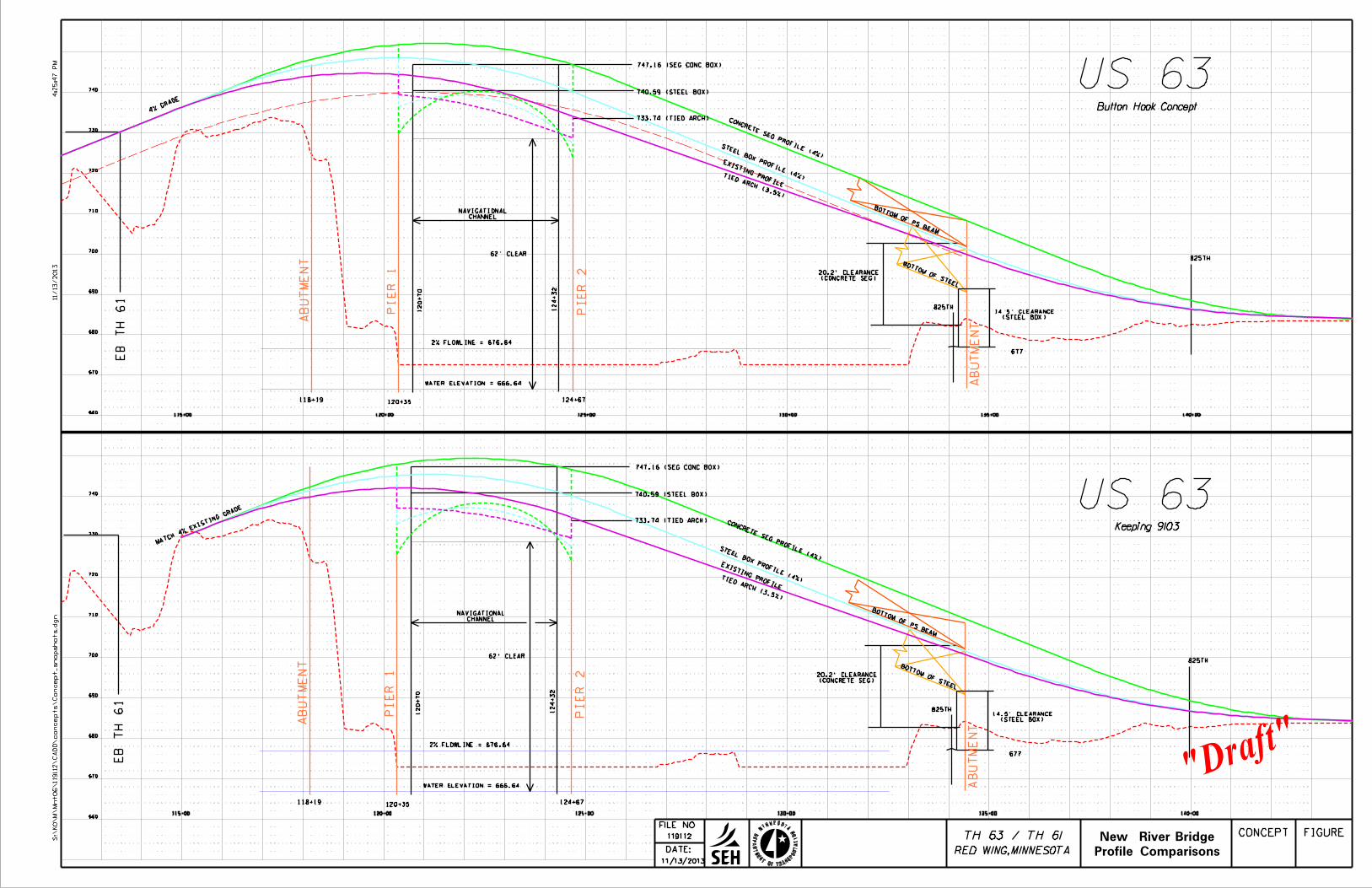
DATE:
FILE NO.
119112
11/13/2013
MINNESOTA
DE
PA
RT
ME
NT OF TRANS
PO
RT
ATIO
N
RED WING, MINNESOTA
11/13/2013
4:2
5:4
7 P
MS:\
KO\
M\
Mnt06\119112\
CA
DD\co
nce
pts\
Co
nce
pt_snapshots.d
gn
TH 63 / TH 61 CONCEPT FIGURE
115+00 120+00 125+00 130+00 135+00 140+00
abut
ment
abut
ment
Pier 1
Pier 2
120+35 124+67118+19
62’ clear
EB
TH 61
Bottom of PS Beam
825th
825th
Bottom of Steel
existing profile
Water Elevation = 666.64
677
12
0+7
0
12
4+3
2
740.59 (steel Box)
747.16 (seg conc Box)
2% Flowline = 676.64
733.74 (Tied Arch)
ChannelNavigational
Tied Arch (3.5%)
(Steel Box)14.5’ Clearance
Steel Box Profile (4%)
Concrete SeG Profile (4%)
(Concrete Seg)20.2’ Clearance
Matc
h 4%
Existi
ng Gr
ade
115+00 120+00 125+00 130+00 135+00 140+00
abut
ment
ab
ut
ment
Pier 1
Pier 2
120+35 124+67118+19
62’ clear
EB
TH 61
Bottom of PS Beam
825th
825th
Bottom of Steel
existing profile
Water Elevation = 666.64
677
12
0+7
0
12
4+3
2
740.59 (steel Box)
747.16 (seg conc Box)
2% Flowline = 676.64
733.74 (Tied Arch)
ChannelNavigational
Tied Arch (3.5%)
(Steel Box)14.5’ Clearance
Steel Box Profile (4%)
Concrete SeG Profile (4%)
(Concrete Seg)20.2’ Clearance
US 63
"Draft"
670
740
660
680
690
700
710
720
730
660
670
740
680
690
700
710
720
730
US 63
Button Hook Concept
Keeping 9103
4% Gr
ade
Profile Comparisons
New River Bridge

AppendixBBridgeSectionComparisons


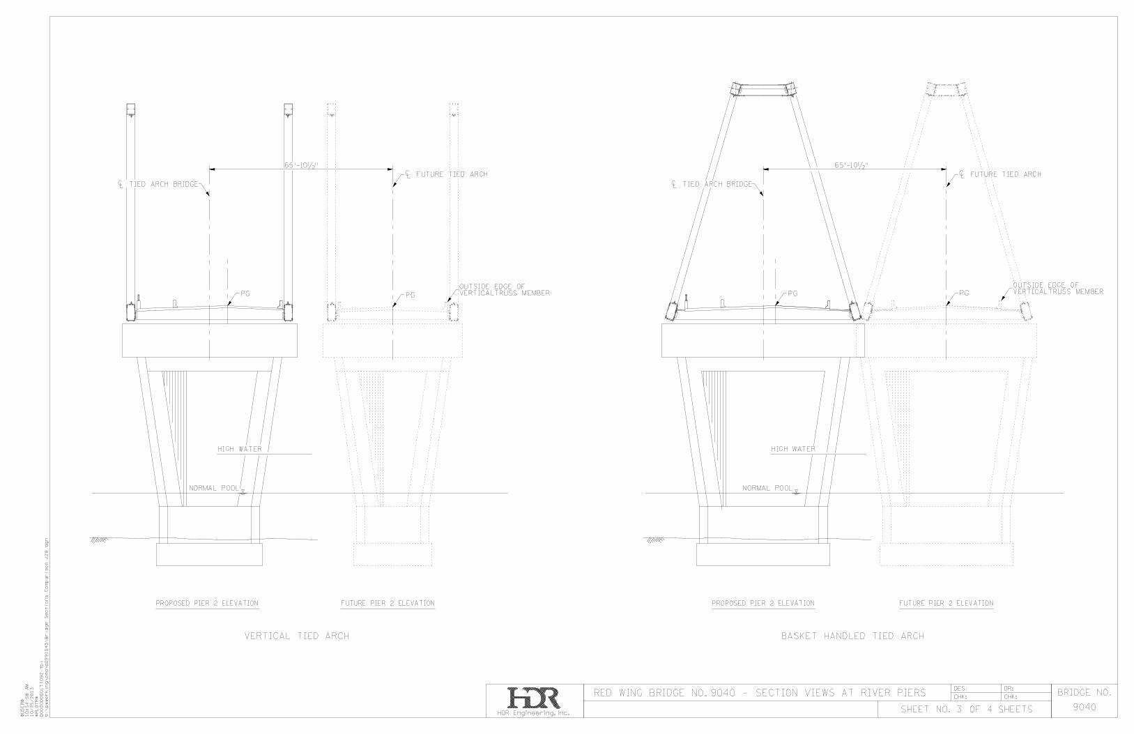


AppendixCConceptCostEstimates
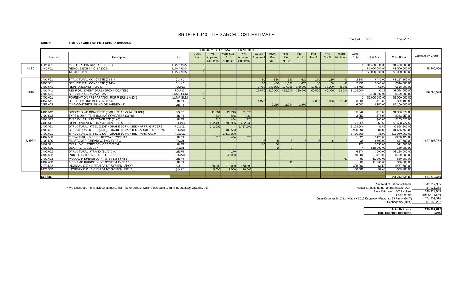
Checked: CRS 10/23/2013Option:
2021.601 MOBILIZATION RIVER BRIDGES LUMP SUM 1 1 $1,400,000.00 $1,400,000.002442.501 REMOVE EXISTING BRIDGE LUMP SUM 1 1 $1,000,000.00 $1,000,000.00
AESTHETICS LUMP SUM 1 1 $3,000,000.00 $3,000,000.00
2401.501 STRUCTURAL CONCRETE (3Y43) CU YD 80 560 880 620 170 150 80 2,540 $440.00 $1,117,600.002401.501 STRUCTURAL CONCRETE (1A43) CU YD 80 400 1,300 470 80 80 80 2,490 $340.00 $846,600.002401.541 REINFORCEMENT BARS POUND 8,700 140,000 157,000 140,000 15,000 15,000 8,700 484,400 $1.07 $518,308.002401.541 REINFORCEMENT BARS (EPOXY COATED) POUND 13,000 320,000 482,500 320,000 60,000 60,000 13,000 1,268,500 $1.21 $1,534,885.002401.601 STRUCTURE EXCAVATION LUMP SUM 1 1 $100,000.00 $100,000.002401.601 FOUNDATION PREPARATION FOR PIERS 1 AND 2 LUMP SUM 1 1 $2,000,000.00 $2,000,000.002452.511 STEEL H-PILING DELIVERED 14" LIN FT 1,340 2,090 2,090 1,340 6,860 $13.00 $89,180.002453.603 C-I-P CONCRETE PILING DELIVERED 42" LIN FT 2,250 2,250 1,500 6,000 $350.00 $2,100,000.00
2401.512 BRIDGE SLAB CONCRETE (3Y36) - SLAB (9 1/2" THICK) SQ FT 11,304 22,713 51,025 85,042 $16.00 $1,360,672.002401.513 TYPE MOD F (TL-4) RAILING CONCRETE (3Y46) LIN FT 432 868 1,950 3,250 $75.00 $243,750.002401.513 TYPE P-1 RAILING CONCRETE (3Y46) LIN FT 216 434 975 1,625 $65.00 $105,625.002401.541 REINFORCEMENT BARS (STAINLESS STEEL) POUND 102,492 205,936 462,638 771,065 $3.50 $2,698,727.502402.521 STRUCTURAL STEEL (3309) - GRADE 50 PAINTED - APPR. GIRDERS POUND 542,000 2,727,000 3,269,000 $1.80 $5,884,200.002402.521 STRUCTURAL STEEL (3309) - GRADE 50 PAINTED - ARCH FLOORBMS POUND 908,590 908,590 $1.80 $1,635,462.002402.521 STRUCTURAL STEEL (3309) - GRADE 50 PAINTED - MAIN ARCH POUND 2,410,000 2,410,000 $5.00 $12,050,000.002402.583 METAL RAILING FOR BIKEWAYS TYPE M-1 LIN FT 216 434 975 1,625 $125.00 $203,125.002402.590 ELASTOMERIC BEARING PAD TYPE X EACH 5 5 5 5 5 5 5 35 $500.00 $17,500.002402.591 EXPANSION JOINT DEVICES TYPE 4 LIN FT 60 60 120 $350.00 $42,000.002402.595 BEARING ASSEMBLY EACH 2 2 4 $10,000.00 $40,000.002402.602 STRUCTURAL STRAND (2 1/2" DIA.) LIN FT 4,276 4,276 $500.00 $2,138,000.002402.602 POST-TENSIONING FOR TIE GIRDER POUND 40,000 40,000 $10.00 $400,000.002402.603 MODULAR BRIDGE JOINT SYSTEM TYPE 6 LIN FT 60 60 $1,000.00 $60,000.002402.603 MODULAR BRIDGE JOINT SYSTEM TYPE 12 LIN FT 60 60 $1,600.00 $96,000.002479.502 INORGANIC ZINC-RICH PAINT SYSTEM (SHOP) SQ FT 35,000 110,000 160,000 305,000 $1.50 $457,500.002479.503 INORGANIC ZINC-RICH PAINT SYSTEM (FIELD) SQ FT 3,500 11,000 16,000 30,500 $2.40 $73,200.00
Subtotal $41,212,334.50 $41,212,335
Subtotal of Estimated Items $41,212,335* Miscellaneous items include elements such as wing/mask walls, slope paving, lighting, drainage systems, etc. *Miscellaneous Items Not Estimated (10%) $4,121,233
Base Estimate in 2012 dollars $45,333,568Engineering $9,066,713.59
Base Estimate in 2012 dollars x 2018 Escalation Factor (1.33 Per MnDOT) $72,352,374Contingency (10%) $7,235,237
Total Estimate $79,587,612Total Estimate (per sq ft) $936
SUPER
SUB
MISC
BRIDGE 9040 - TIED ARCH COST ESTIMATE
Tied Arch with Steel Plate Girder Approaches
SUMMARY OF ESTIMATED QUANTITIESOption Total
South AbutmentItem No. Description Unit
Lump Sum
River Pier
No. 1
River Pier
No. 2
Pier No. 3
Main Span Arch
Superstr.
WI Approach Superstr.
MN Approach Superstr.
Pier No. 5
Pier No. 4 Total Price
Estimate by GroupNorth
Abutment Unit Price
$8,306,573
$27,505,762
$5,400,000

Checked CRS 10/23/2013Notes:
2021.601 MOBILIZATION RIVER BRIDGES LUMP SUM 1 1 $1,000,000.00 $1,000,000.002442.501 REMOVE EXISTING BRIDGE LUMP SUM 1 1 $1,000,000.00 $1,000,000.00
AESTHETICS LUMP SUM 1 1 $3,000,000.00 $3,000,000.00
2401.501 STRUCTURAL CONCRETE (3Y43) CU YD 80 560 880 620 170 150 150 150 80 2,840 $440.00 $1,249,600.002401.501 STRUCTURAL CONCRETE (1A43) CU YD 80 400 1,300 470 80 80 80 80 80 2,650 $340.00 $901,000.002401.541 REINFORCEMENT BARS POUND 8,700 140,000 157,000 140,000 15,000 15,000 15,000 15,000 8,700 514,400 $1.07 $550,408.002401.541 REINFORCEMENT BARS (EPOXY COATED) POUND 13,000 320,000 482,500 320,000 60,000 60,000 60,000 60,000 13,000 1,388,500 $1.21 $1,680,085.002401.601 STRUCTURE EXCAVATION LUMP SUM 1 1 $100,000.00 $100,000.002401.601 FOUNDATION PREPARATION FOR PIERS 1 AND 2 LUMP SUM 1 1 $2,000,000.00 $2,000,000.002452.511 STEEL H-PILING DELIVERED 14" LIN FT 1,340 2,090 2,090 2,090 2,090 1,340 11,040 $13.00 $143,520.002453.603 C-I-P CONCRETE PILING DELIVERED LIN FT 2,250 2,250 1,500 6,000 $350.00 $2,100,000.00
2401.512 BRIDGE SLAB CONCRETE (3Y36) - SLAB (9 1/2" THICK) SQ FT 39,825 45,216 85,041 $20.00 $1,700,820.002401.513 TYPE MOD F (TL-4) RAILING CONCRETE (3Y46) LIN FT 1,522 1,728 3,250 $75.00 $243,750.002401.513 TYPE P-1 RAILING CONCRETE (3Y46) LIN FT 761 864 1,625 $65.00 $105,625.002401.541 REINFORCEMENT BARS (STAINLESS STEEL) POUND 361,090 437,500 798,590 $3.50 $2,795,063.252402.521 STRUCTURAL STEEL (3309) - GRADE 50 PAINTED - GIRDER STEEL POUND 2,589,000 2,589,000 $1.80 $4,660,200.002402.522 STRUCTURAL STEEL (3309) - GRADE 50 PAINTED - DETAIL STEEL POUND 810,600 810,600 $3.20 $2,593,920.002402.521 STRUCTURAL STEEL (3309) - GRADE 70 PAINTED POUND 1,655,200 1,655,200 $2.30 $3,806,960.002402.583 METAL RAILING FOR BIKEWAYS TYPE M-1 LIN FT 761 864 1,625 $125.00 $203,125.002402.591 EXPANSION JOINT DEVICES TYPE 4 LIN FT 60 60 120 $350.00 $42,000.002402.590 ELASTOMERIC BEARING PAD TYPE X EACH 6 12 12 12 12 6 60 $500.00 $30,000.002402.595 BEARING ASSEMBLY (325 KIP) EACH 3 3 6 $2,500.00 $15,000.002402.595 BEARING ASSEMBLY (2400 KIP) EACH 3 3 6 $15,000.00 $90,000.002402.603 MODULAR BRIDGE JOINT SYSTEM TYPE 6 LIN FT 0 $850.00 $0.002402.603 MODULAR BRIDGE JOINT SYSTEM TYPE 9 LIN FT 60 60 120 $1,100.00 $132,000.002405.502 PRESTRESSED CONCRETE BEAMS 82MW LIN FT 4,590 4,590 $300.00 $1,377,000.002479.502 INORGANIC ZINC-RICH PAINT SYSTEM (SHOP) - EXTERIOR (FULL SYS) SQ FT 82,400 82,400 $1.50 $123,600.002479.503 INORGANIC ZINC-RICH PAINT SYSTEM (FIELD) - EXTERIOR (FULL SYS) SQ FT 8,240 8,240 $2.40 $19,776.002479.502 INORGANIC ZINC-RICH PAINT SYSTEM (SHOP) - INTERIOR (1 COAT) SQ FT 125,600 125,600 $1.15 $144,440.00
Subtotal $31,807,892.25 $31,807,892
Subtotal of Estimated Items $31,807,892* Miscellaneous items include elements such as wing/mask walls, slope paving, lighting, drainage systems, etc. *Miscellaneous Items Not Estimated (10%) $3,180,789
Base Estimate in 2012 dollars $34,988,681Engineering $6,997,736.30
Base Estimate in 2012 dollars x 2018 Escalation Factor (1.33 Per MnDOT) $55,841,936Contingency (10%) $5,584,194
Total Estimate $61,426,129Total Estimate (per sq ft) $722
BRIDGE 9040 - STEEL BOX GIRDER COST ESTIMATE
Variable Depth (Haunched) Three Span Continuous Steel Box Girder (216' - 432' - 216'), 3 Girder Cross Section, Option 3 (12'-0" maximum girder depth, 7'-6" minimum girder depth) with PS Beam Approach Spans @ 152'-0" each
SUMMARY OF ESTIMATED QUANTITIES
Estimate by GroupItem No. Description Unit
Lump Sum
MN Approach Superstr.
3-Span Steel Box
Girder
South Abutment
River Pier
No. 1
River Pier
No. 2
Pier No. 3
Pier No. 4
Pier No. 7
$5,000,000MISC
Pier No. 6
SUB $8,724,613
SUPER $18,083,279
Pier No. 5
North Abutment
Option Total Unit Price Total Price
na

Checked: CRS 10/23/2013Notes:
2021.601 MOBILIZATION RIVER BRIDGES LUMP SUM 1 1 $950,000.00 $950,000.002442.501 REMOVE EXISTING BRIDGE LUMP SUM 1 1 $1,000,000.00 $1,000,000.00
AESTHETICS LUMP SUM 1 1 $3,000,000.00 $3,000,000.00
2401.501 STRUCTURAL CONCRETE (3Y43) CU YD 80 560 880 620 170 150 150 150 80 2,840 $440.00 $1,249,600.002401.501 STRUCTURAL CONCRETE (1A43) CU YD 80 400 1,300 470 80 80 80 80 80 2,650 $340.00 $901,000.002401.541 REINFORCEMENT BARS POUND 8,700 140,000 157,000 140,000 15,000 15,000 15,000 15,000 8,700 514,400 $1.07 $550,408.002401.541 REINFORCEMENT BARS (EPOXY COATED) POUND 13,000 320,000 482,500 320,000 60,000 60,000 60,000 60,000 13,000 1,388,500 $1.21 $1,680,085.002401.601 STRUCTURE EXCAVATION LUMP SUM 1 1 $100,000.00 $100,000.002401.601 FOUNDATION PREPARATION PIERS 1 AND 2 LUMP SUM 1 1 $2,000,000.00 $2,000,000.002452.511 STEEL H-PILING DRIVEN/DELIVERED 14" LIN FT 1,340 2,090 2,090 2,090 2,090 1,340 11,040 $13.00 $143,520.002452.603 C-I-P CONCRETE PILING DRIVEN/DELIVERED 42" LIN FT 2,250 2,250 1,500 6,000 $350.00 $2,100,000.00
2401.512 BRIDGE SLAB CONCRETE (3Y36) - SLAB (9 1/2" THICK) SQ FT 39,825 39,825 $20.00 $796,500.002401.513 TYPE MOD F (TL-4) RAILING CONCRETE (3Y46) LIN FT 1,522 1,728 3,250 $75.00 $243,750.002401.513 TYPE P-1 RAILING CONCRETE (3Y46) LIN FT 761 864 1,625 $65.00 $105,625.002401.541 REINFORCEMENT BARS (EPOXY COATED) POUND 1,080,000 1,080,000 $1.25 $1,350,000.002401.541 REINFORCEMENT BARS (STAINLESS STEEL) POUND 361,090 360,000 721,090 $3.50 $2,523,815.002401.607 STRUCTURAL CONCRETE (xxxx) CU YD 5,750 5,750 $1,000.00 $5,750,000.002401.618 BRIDGE DECK PLANING SQ FT 31,104 31,104 $4.00 $124,416.002402.583 METAL RAILING FOR BIKEWAYS TYPE M-1 LIN FT 761 864 1,625 $125.00 $203,125.002402.590 ELASTOMERIC BEARING PAD TYPE X EACH 6 6 6 6 6 6 36 $500.00 $18,000.002402.591 EXPANSION JOINT DEVICES TYPE 4 LIN FT 60 60 120 $350.00 $42,000.002402.595 BEARING ASSEMBLY (325 KIP) EACH 0 $2,500.00 $0.002402.595 BEARING ASSEMBLY (1200 KIP) EACH 2 2 4 $8,000.00 $32,000.002402.595 BEARING ASSEMBLY (2400 KIP) EACH 0 $15,000.00 $0.002402.603 MODULAR BRIDGE JOINT SYSTEM TYPE 6 LIN FT 0 $850.00 $0.002402.603 MODULAR BRIDGE JOINT SYSTEM TYPE 9 LIN FT 60 60 120 $1,100.00 $132,000.002404.618 CHIP SEAL WEARING COURSE SQ FT 31,104 31,104 $4.00 $124,416.002405.502 PRESTRESSED CONCRETE BEAMS 82MW LIN FT 4,590 4,590 $300.00 $1,377,000.002405.601 SEGMENTAL ERECTION EQUIPMENT LUMP SUM 1 1 $2,500,000.00 $2,500,000.002405.608 POST-TENSIONING STEEL STRANDS (TRAN) POUND 40,200 40,200 $5.00 $201,000.002405.608 POST-TENSIONING STEEL STRANDS (LONG) POUND 540,000 540,000 $3.50 $1,890,000.002405.609 POST-TENSIONING STEEL BARS (1-3/8") POUND 18,400 18,400 $6.00 $110,400.00
Subtotal $31,198,660.00 $31,198,660
Subtotal of Estimated Items $31,198,660* Miscellaneous items include elements such as wing/mask walls, slope paving, lighting, drainage systems, etc. *Miscellaneous Items Not Estimated (10%) $3,119,866
Base Estimate in 2012 dollars $34,318,526Engineering (20%) $6,863,705.20
Base Estimate in 2012 dollars x 2018 Escalation Factor (1.33 Per MnDOT) $54,772,367Contingency (10%) $5,477,237
Total Estimate $60,249,604Total Estimate (sq ft) $708
River Pier
No. 1
River Pier
No. 2
Pier No. 3 Total PriceUnit Price
Pier No. 4
MISC $4,950,000
BRIDGE 9040 - SEGMENTAL CONCRETE BOX GIRDER COST ESTIMATE
Variable Depth (Haunched) Three Span Segmental Concrete Box (216' - 432' - 216') ,21'-0" maximum girder depth, 11'-0" minimum girder depth, with PS Beam Approach Spans @ 152'-0" each
SUMMARY OF ESTIMATED QUANTITIES
Estimate by GroupItem No. Description Unit
Lump Sum
MN Approach Superstr.
3-Span Conc. Box (Option 1)
n/a South Abutment
Pier No. 5
Pier No. 6
Pier No. 7
North Abutment
Option Total
SUB $8,724,613
SUPER $17,524,047

AppendixDNewStructureAlternativesMemo

MEMORANDUM
TO: Chad Hanson, MnDOT Project Manager
Chris Hiniker, SEH Project Manager
FROM: Todd Lang, HDR
DATE: March 4, 2013 – Final
RE: Red Wing Bridge Project - Bridge 9040 New Structure Alternatives
PURPOSE AND BACKGROUND
MnDOT initiated the Red Wing Bridge Project in January 2012. The project includes the US 63 (Eisenhower) Bridge 9040 over the Mississippi River and the US 63 Bridge 9103 over US 61, as well as the highway connections to US 61, Minnesota TH 58, and approach roadways in the State of Wisconsin. The Eisenhower Bridge carries US 63 across the river from Red Wing and connects to the state of Wisconsin. The bridge provides the only regional crossing of the river for over 30 miles upstream or downstream for several communities on both the Wisconsin and Minnesota sides of the river.
As documented in the project’s Purpose and Need Statement, the primary purpose of the project is to provide a structurally sound crossing of the Mississippi River and US 61. Secondarily, the project will study future capacity needs and the accommodation of pedestrian/bicycle traffic across the Mississippi River and US 61.
This memorandum documents the initial screening of new bridge alternative structure types that could be built parallel to the rehabilitated existing Bridge 9040 as the second half of a four-lane crossing, or in place of the existing Bridge 9040 as a new two-lane or four-lane bridge. It documents initial screening, with the intent to provide information sufficient to narrow the number of the alternatives under consideration. A more detailed study of the remaining alternatives will be undertaken in the next phase.
GENERAL DESIGN CONSIDERATIONS
Structure Limits and Alignment
All of the proposed bridge alternates discussed in this memo will be on or near the existing alignment of Bridge 9040. The south abutment is proposed to be located in line with the existing south abutment. For the purposes of this first screening, it has been assumed that the north abutment will also be aligned with the existing north abutment. This produces an overall mainline bridge length of approximately 1,625 feet for all alternatives studied during this phase. During the subsequent phases of this study, shortening the bridge by approximately 90’ at the north end will be investigated for potential efficiencies; however, the results of that investigation will not affect this initial screening.
The main unit of the existing bridge is comprised of a three-span continuous through truss with spans of 216’-432’-217’with the 432’ main span being over the main channel of the Mississippi River. At the north end of the main unit there are six steel girder approach spans of 125’-150’-150’-150’-125’-60’ for a total of 760’. See Figure 1 on the following page for an aerial view of the existing bridge layout.

Red Wing Bridge Project - Bridge 9040 New Structure Alternatives March 4, 2013 Page 2
FIGURE 1 – BRIDGE LAYOUT
Grade
Existing Bridge 9040 has approximately a 4% grade rising up to the bridge from both the Minnesota and Wisconsin approach roadways. The southernmost 930’ of the existing bridge is in a 1,300’ long vertical curve that starts approximately 370’ south of the south abutment. Preliminary geometric studies indicate that the starting station and length of the vertical curve, and the grade coming out of the vertical curve can be adjusted such that the profile grade in the main span can be raised by a maximum of approximately 10’ while maintaining the 4% approach grade. Due to geometric constraints south of the bridge, it is desirable to maintain the 4% grade coming onto the bridge, but depending on decisions regarding Bridge 9103 some potential structure types may require a grade increase to 5%.
The existing bridge truss spans have a structure depth from profile grade to low steel of approximately 4.1’. Preliminary coordination with the United States Coast Guard (USCG) has indicated that the vertical and horizontal navigational clearances for any new bridges or parallel structures will have to match the existing 432’ main span. Therefore, any increase in structure depth in the main span will have to be accommodated by a grade increase.
Typical Sections
The existing bridge has a 30’ clear roadway width between curbs, 2’-6” wide raised curbs on both sides of the road and 1’-2” wide concrete parapets on the outsides for a total out-to-out deck width of 37’-4” (see Figure 2 at the end of this memo). If the existing bridge is rehabilitated and a new two-lane bridge is constructed parallel to it, the existing bridge will become a two-lane northbound bridge with two 12’

Red Wing Bridge Project - Bridge 9040 New Structure Alternatives March 4, 2013 Page 3 lanes, a 4’ inside shoulder, a 6’ outside shoulder and two 1’-8” wide concrete barriers to retain its 37’-4” deck width. The new structure would have a similar configuration carrying two southbound lanes but would include a 12’ wide trail that would be separated from the traffic by a 1’-6” wide barrier. The barrier on the outside of the trail would be 1’-2” wide for a total deck width of 50’-4” (see Figure 3 at the end of this memo). The clear distance between the outside of the rehabilitated existing truss and the new parallel structure will need to be a minimum of 10’ to provide inspection access between the structures and to provide clearance between adjacent substructure units for the new and existing bridges.
If it is determined that the existing truss will not be rehabilitated, it will be replaced by a new two-lane bridge constructed parallel to the existing bridge or a four-lane bridge. A new two-lane bridge will have a cross section similar to the new parallel structure described above but as a two-way structure, it will likely require 10’ shoulders on both sides leading to a total deck width of 60’-4” (see Figure 4 at the end of this memo). The 10’ shoulder requirement will be confirmed in later studies. A new four-lane bridge with two lanes in each direction would have 4’ inside and 6’ outside shoulders, a 12’ wide trail, and depending on the structure type and construction staging could have as narrow as a 1’-9” wide median barrier between opposing inside shoulders (see Figure 5 at the end of this memo).
Barn Bluff is located just to the east of the existing structure on the Minnesota approach and is on the National Register of Historic Places (NRHP). To avoid impacting Barn Bluff, the eastern limits of the selected structure alternative and approach roadway cannot move any further east than the eastern limits of the current bridge. There is an ADM facility that is approximately 82’ west of the western limits of the existing bridge that would be costly to impact, and alternative development will therefore focus on avoiding or minimizing impacts to ADM. Given the above limits and that the existing structure is approximately 42’ out-to-out of structure, the selected alternative will need to have a total section width of less than 124’.
Vertical Clearance
As mentioned previously, the USCG has indicated that the existing navigational clearances must be maintained for any new structures. This includes the existing 64.5’ above normal pool in the main river span.
In addition to the Mississippi River, the existing bridge crosses over Canadian Pacific Railways (CPR) and the Island Campground and Marina. The southernmost span, Span 1, crosses six sets of CPR tracks with an existing vertical clearance of approximately 51’. This is much greater than the 23’-0” required by AREMA so railroad clearance should not have any effect on the allowable structure depths of the alternatives. Likewise, the existing vertical clearance above the Island Campground and Marina in Spans 4 and 5 is over 40’ and will not impact the structure types studied.
Horizontal Clearance
Horizontal clearance from the centerline of the CPR tracks to the face of piers shall be a minimum of 25’ to preclude the use of crash walls. Should an alternate place piers between 12 and 25 feet, crash walls will be required in accordance with AREMA. No clearance shall be less than 12 feet. The alternatives in this memo all maintain a minimum of 25 feet from piers to the centerline of tracks to match the existing horizontal clearance. It should be noted that the existing Pier 1 is located within the CPR right-of-way and therefore any new pier constructed for a parallel bridge located adjacent to Pier 1 will also be on CPR right-of-way.
Horizontal clearance for the Mississippi River navigation channel is dictated by the USCG, and varies along the river. As noted previously, the USCG has indicated that the main river span will need to remain

Red Wing Bridge Project - Bridge 9040 New Structure Alternatives March 4, 2013 Page 4 432’ or greater. If a new pier is built to align with the existing Pier 2 it will likely have impacts on the location of some of Island Marina’s boat slips.
With the tight horizontal clearances to Pier 1 between the CPR tracks and the Mississippi River, Pier 1 will be lined up with the existing Pier 1 in all of the alternatives in this memo. Also, Pier 2 has been aligned with existing Pier 2 in almost all alternatives to minimize the span length of the main river span and to avoid hydraulic impacts. In addition, all piers within the river’s floodplain should be aligned with the existing piers to minimize the hydraulic impacts. Although the clearance between the existing bridge and the ADM facility to the west is limited, there will be enough room to construct these piers (see Figures 7 and 8 at the end of this memo).
Aesthetics
The existing truss is visible from many properties that are on or eligible for the NRHP, and is a prominent piece of the City’s skyline. As such, the appearance of the new structure alternatives will be important. How the alternatives fit with the surroundings and in the case of a parallel structure, how they fit with the existing truss will be evaluated in the next phase of the replacement alternatives study.
Maintenance of Traffic
The existing US 63 crossing at Red Wing is the only crossing for over 30 miles upstream or downstream. The bridge is used by commuters, commercial vehicles and recreational vehicles, and emergency service vehicles to travel between communities on opposite sides of the Mississippi River everyday. The 60 mile detour created by any closure of the crossing will have a great impact on this traffic and emergency response time.
Any specific impacts on maintenance of traffic that need to be considered for the different alternates will be discussed in detail for that alternate later in this report.
SPAN ARRANGEMENT STUDY ALTERNATES
Based on the capabilities of various bridge types and experience on similar major projects, the following alternate structure types for the main river span were considered:
Alternate 1 – Tied Arch
Alternate 2 – Simple Span Truss
Alternate 3 – Three-Span Continuous Truss
Alternate 4 – Extradosed Bridge
Alternate 5 – Cable-Stayed Bridge
Alternate 6 – Concrete Segmental Box Girders
Alternate 7 – Steel Box Girders
In the sections that follow, these seven structure types are presented and discussed. Following these sections is a discussion of the selection of the most appropriate approach units for each of these alternates.
ALTERNATE 1 – TIED ARCH
The proposed structure for Alternate 1 is a tied arch. The main span length of 432’-0” bridges the current navigation channel of the Mississippi River. The arch rise would be approximately 75’above the

Red Wing Bridge Project - Bridge 9040 New Structure Alternatives March 4, 2013 Page 5 roadway, yielding a span-to-rise ratio of 6, which provides an efficient and geometrically proportional structure. The arches could be vertical or could be a basket-handle, and if vertical using free standing arches instead of bracing could be investigated. The tie girder is suspended from the arch rib by suspenders. The suspenders could run vertically in a conventional tied arch or diagonally in a pattern of diamond-shapes forming a network tied arch. See Figure 6 at the end of this memo for an elevation view of a network tied arch.
The tie girders are primarily tension members that resist the thrust of the arch rib. They would be located outside of the bridge deck at about the same elevation as the bridge’s floor system. These members are critical elements that must be designed to be fatigue and fracture resistant per MnDOT practice, including a redundant system to prevent failure of the tied arch system. Several alternative means of achieving redundancy have been investigated and used on recent projects, such as the Lowry Avenue Bridge in Minneapolis and the Hastings Bridge. These include; 1) designing the tie girders to withstand a complete fracture of either one web or one flange without yielding the remaining section, thereby allowing sufficient time to identify the issue and make repairs (the webs and flanges are connected by a bolted connection, which eliminates potential crack propagation between the web and flange plates of the ties) or a second redundant tie girder would be provided, 2) post-tensioning the steel tie girder to eliminate tension in the member, 3) designing the tie girders to consist of a post tensioned concrete girder with tension carried by the tendons and provisions for adding future tendons if needed, thus eliminating many of the fatigue and fracture issues of a traditional steel tension tie.
As mentioned above, the arch suspenders are attached between the arch rib and tie girder, and could be either vertical or diagonal. The use of diagonal suspenders in a network tied arch has been found to be more efficient than the conventional vertical suspenders; however the diagonal pattern of the suspenders can make inspection access difficult.
The floor system for a tied arch would be made up of steel floorbeams and stringers. The floorbeams would be located at the locations where the suspenders attach to the tie girder and would run transverse to the roadway. Stringers would span between floorbeams, run parallel to the roadway and would support a concrete deck. The arch and tie girder are the primary load carrying system and are outside and generally above the deck, yielding a shallow structure depth from the profile grade to the low member elevation. How shallow the structure depth is will depend on how the stringers are connected to the floorbeams. The stringers can either be framed into the floorbeams or stacked on top of them. If they are framed-in, this structure type would only require a 2’ grade raise but if they are stacked it would increase to approximately 5’. Because there are advantages and disadvantages to each type of floor system, this should be investigated in greater detail if this structure type is studied further.
Construction
Two possible methods of construction are envisioned for the tied arch. The two methods include cantilevered arch erection with the use of backstays, and a float-in construction sequence. The use of falsework to support the structure in the navigation channel would not be practical at this site due to the expected width of navigation channel required during the construction process, and the expense of falsework and falsework protection in the river.
Cantilevered erection is performed by supporting the arch ribs with backstays during construction. The backstays attach through towers to temporary anchor blocks behind the river piers and connect to the arch ribs at critical locations to support the dead load of the arch rib and construction loads. Following the completion of the arch rib construction, the arch ribs and backstays support the tie girders during erection. The floor system is constructed after the tie girder erection is complete and the suspenders are installed.

Red Wing Bridge Project - Bridge 9040 New Structure Alternatives March 4, 2013 Page 6 Cantilevered arch erection is an efficient method of construction. The construction engineering required is of moderate complexity, and the cost of the erection temporary works is offset by reduced construction time. Also, cantilevered arch erection is a common method of erection and should not preclude erectors from bidding on the project.
The erection of the arch for a float-in scheme is performed off-site. It requires the use of staging areas that are located nearby and have access to the river. The river bridge arch ribs, tie girders, suspenders, floorbeams, rib bracing, and tie bracing are assembled on falsework. The off-site location provides the erector with safer working conditions and minimal temporary works at the final project site. After the arch erection is complete, the structure is floated to the project site and lifted or lowered into place atop the river pier bearings. Once the arch is in place, the stringers and deck forms are installed, and the deck is placed. Float-in erection allows the structural steel for the main span to be assembled while the substructure and approach span construction is also performed. This sequence can reduce the construction time for the project. Construction engineering is limited to the design of the falsework used to support the arch members during erection and the jacking system used to set the bridge in the final position. The major drawback is the transportation of the completed structure to the project site and lifting the completed structure into the final position. This specialized form of erection could preclude some erectors from bidding on the construction project. However, the float-in method has previously been used for the truss at Wabasha, MN, and the tied arches at Hastings and LaCrosse, WI.
Future Inspection, Maintenance and Expansion
Inspection access to the floor system and tied arch would be provided by an Under Bridge Inspection Vehicle (UBIV). As mentioned earlier, the use of a network tied arch would make moving the arm of the UBIV in and out of the suspenders more difficult than a conventional tied arch. Access to the arch, including the suspender connections to the arch, would be by manlifts that would be positioned on the bridge deck.
Future maintenance of the structure includes periodic inspections, repainting, deck replacement, and future wearing surface application. The geometric constraints of the arch make widening the deck for additional lanes in the future not feasible unless accommodations are made in the original design to facilitate the addition of a third arch at a later date. This would require that the arch that would become the middle arch in the future, be designed from the beginning to a higher capacity than the outside arches. Adding a separate, second arch bridge parallel to the first could also be considered but is not likely to be feasible due to the narrow constraints between ADM and Barn Bluff.
Deck replacement is feasible while maintaining traffic. Approximately one half of the bridge deck is replaced while maintaining traffic on the other side of the bridge. Once half the deck is completed, the traffic is shifted to complete the other half.
Aesthetics
Conventional Tied Arch bridges are both powerful and elegant. The upward curve of the arch ribs gives the sense of the bridge flowing away from the roadway below. The minimal structural elements extending above the bridge deck grant an unrestricted view while looking from the roadway to the landscape beyond the bridge. Also, the suspender cables provide minimal interference to the observer from either up or down stream and traffic traversing the bridge.
If used as a parallel structure with the existing rehabilitated truss left in place, a tied arch would likely fit well with the existing structure. Both an arch and the existing truss are above deck steel superstructures with fairly shallow floor systems and a more classical appearance. At its high point the arch would extend

Red Wing Bridge Project - Bridge 9040 New Structure Alternatives March 4, 2013 Page 7 about 75’ above the roadway which compares fairly well to the existing truss bridge which extends about 50’ above the roadway, and is still over 100’ lower than the top of Barn Bluff.
ALTERNATE 2 – SIMPLE SPAN TRUSS
Alternate 2 is a simple span through truss consisting of total length of 432’. The truss is a variable depth Pratt truss. The depth of the truss increases from the portals to the centerline of the bridge where it will be approximately 70’ above the deck. Similar to the tied arch alternate the entire deck section will be inside the trusses. An elevation view of this structure type is shown in Figure 9 at the end of this memo.
The chord members and compression diagonals would be box-shaped sections. The tension diagonals would likely be fabricated I-sections. A steel truss is a non-redundant structure with fracture critical members. Therefore, the truss tension members which would be the lower chord members and some of the diagonals would have to be designed to incorporate redundancy into the design and/or precompression will need to be introduced to keep them out of tension. The incorporation of redundant systems would be required by MnDOT policy and practice. If this alternative is carried forward for more detailed studies, acceptable methods of providing redundancy will need to be studied in greater detail. It likely will also be a significant structural engineering challenge to develop a detail satisfactory to the designer and owners.
The floor system for a truss will be similar to that described above for the tied arch alternate. The floorbeams will be located at every truss joint and the stringers will span between floorbeams. The structure depth from the profile grade to the low member elevation for this alternate is fairly shallow. Similar to the tied arch, the floor system for a truss can be framed-in or stacked. Therefore the required grade raise for this alternate will be either 2’ or 5’ depending on the floor system selected.
Construction
Two methods of construction are feasible for the simple span truss and include cantilevered construction with falsework in the river or float-in construction.
The use of falsework in the river will depend on the minimum navigation channel required by the Coast Guard during construction and may not be feasible. After the trusses and floorbeams are erected, the stringers and deck would be installed to complete the construction. This method of construction is moderately complex with moderate construction engineering required. Using temporary falsework in the river and protection of the temporary falsework will increase the cost of this option.
The assembly of the truss for a float-in scheme is performed off-site. The entire span including both trusses, floorbeams, top and bottom lateral bracing and sway frames is erected on temporary falsework. Performing this work off-site provides safer and more controlled working conditions and eliminates falsework in the navigation channel. Stringers and deck forms could also be placed off-site. However, to limit total weight of the float-in pick, it is assumed that they would be installed after the truss unit is placed on the piers. The completed truss is floated into position and lifted onto the river piers. In a variation of this type of construction the temporary falsework that the truss is assembled on is built at a higher elevation than the piers. This allows the truss to be lowered into place by taking on water in the barges once the truss is positioned over the piers, eliminating the need to lift the truss. The truss at Wabasha, MN was constructed by lowering it into place in this manner.
After the truss is in its final position, the stringers and deck are installed to complete construction. A float-in scheme minimizes construction time by permitting work on the substructure and approach spans to occur concurrently with the main span construction. Construction engineering includes designing falsework during erection and a lifting scheme for final placement. However, the float-in scheme could

Red Wing Bridge Project - Bridge 9040 New Structure Alternatives March 4, 2013 Page 8 also be a drawback as this type of construction may reduce the number of contractors who bid on the project.
Future Inspection, Maintenance and Expansion
Inspection access for the floor system and lower chords would be obtained by using an UBIV. Access to the top chord, diagonals and top lateral bracing would be by climbing or from a manlift located on the deck.
Simple span truss structures are typically considered to be non-redundant. The bottom chord tension members are highly loaded and considered to be fracture critical. These members must be designed, detailed and fabricated according to the fracture critical guide specifications. However, the increased cost of designing to these specifications is partially offset by the reduction in material costs and decreased maintenance costs for a closed member. Even with the addition of redundant systems for tension members noted earlier, it is expected inspection time and effort would continue to be higher than other structure types.
Future maintenance for the simple span truss alternate includes periodic inspections, painting, deck replacement and wearing surface application. Inspecting and painting trusses is a significant maintenance cost due to the number of members that comprise the structure. Maximizing panel lengths reduces the number of members. Additional measures to prevent corrosion include drain holes in the web of inclined I-sections and detailing to prevent ponding.
Deck replacement is feasible while maintaining traffic. Utilizing phased construction, half the deck would be removed while keeping traffic on the other half. Traffic would be switched to the new deck and the other half replaced. Future roadway widening is not possible given the truss configuration unless accommodations are made in the original design to facilitate the addition of a third truss at a later date. This would require that the truss that would become the middle truss in the future, be designed from the beginning to a higher capacity than the outside trusses. Adding a separate, second truss bridge parallel to the first could also be considered but is not likely to be feasible due to the narrow constraints between ADM and Barn Bluff.
Aesthetics
The top chord of a simple span truss has a pleasing arched appearance. However, the lengths of the diagonals toward the center of the bridge could yield a slender, almost spindly appearance. Because sway frames are necessary for stability, the bridge could impart a sense of confinement.
If used as a parallel structure with the existing rehabilitated truss left in place, a simple span truss would fit well with the existing structure. The height of the new truss would be slightly taller than the existing truss since it is a simple span as compared to the existing continuous truss.
ALTERNATE 3 – THREE-SPAN CONTINUOUS TRUSS
Alternate 3 is a three-span continuous through truss with span lengths of 216’-432’-217’, for a total length of approximately 865’. A possible configuration would be a Warren truss. The use of a Warren truss with or without verticals can be studied in greater detail in later studies. Likewise the use of a constant depth or variable depth truss should be studied. The use of a constant depth without verticals would likely be the most economical and have the cleanest appearance, however a variable depth truss with verticals would most closely match the existing bridge. An elevation view of a variable depth truss with verticals can be found in Figure 10 at the end of this memo.

Red Wing Bridge Project - Bridge 9040 New Structure Alternatives March 4, 2013 Page 9 The chord members and compression diagonals would be box-shaped sections. The tension diagonals would likely be fabricated I-sections. A steel truss is a non-redundant structure with fracture critical members. Therefore the truss tension members, which would be the tension chord members and some of the diagonals, would have to be designed to incorporate redundancy into the design and/or precompression will need to be introduced to keep them out of tension. As noted earlier, this would be required by MnDOT policy and practice. With the three-span truss alternate being continuous over the interior piers, it may be possible to take advantage of the continuity in a three-dimensional design and reduce the number of non-redundant members. The use of double members or post-tensioning could also be used to address redundancy issues in this type of structure.
The floor system for this alternate will be similar to the simple span truss. Likewise, the grade raise required for this alternate will be 2’ or 5’ depending on whether the stringers are framed into the floorbeams or stacked on top of them.
Construction
Erection of a continuous truss requires falsework for the end spans only, leaving the full navigation channel open to barge traffic. This may require construction of falsework over the CPR tracks, but due to the extra clearance that is currently provided, this is not anticipated to be a problem. Erection would begin by placing the first few panels of the end spans nearest to the interior piers between the pier and falsework. It is likely that these panels could be erected partially or in their entirety on the ground and lifted into place. The next panels of the middle and end spans would be erected using balanced cantilever construction. Cantilevered construction of the center span would continue past this point by placing counterweights or tie-downs in the end spans. After closure of the middle span, the final panels of each end span would be completed. These panels would be erected last to permit dropping of the ends of the truss to facilitate closure at the center of the bridge at the proper geometry. Once the trusses and floorbeams are in place, the stringers and deck would complete construction.
The balanced cantilever construction method is relatively straightforward. Similar erection methods have been successfully used in the past. The ease and speed of construction is correlated to the number of members and connections that must be made. The number of connections could be minimized by eliminating truss verticals and using a diamond pattern for the top lateral bracing.
Construction complexity and the numbers of constructors available to bid on this structure type would be similar to the simple span truss alternate.
Future Inspection, Maintenance and Expansion
Inspection access for the floor system and lower chords would be obtained by using an UBIV. The elimination of verticals would make access easier by enlarging the openings through which the arm of the UBIV would have to be directed. Access to the top chord, diagonals and top lateral bracing would be by climbing or from a manlift located on the deck.
There is not general agreement as to whether a continuous truss structure can be considered to be redundant. Heavily loaded tension members are usually considered to be fracture critical. The continuity and three-dimensional behavior of the structure would be analyzed to determine which tension members are truly fracture critical. As noted earlier, redundant systems would need to be added to those members in the design.
Future maintenance for the variable depth continuous truss alternate includes periodic inspections, painting, deck replacement and wearing surface application. Painting trusses is a significant maintenance cost due to the number of members. Eliminating verticals and maximizing panel lengths would reduce

Red Wing Bridge Project - Bridge 9040 New Structure Alternatives March 4, 2013 Page 10 the number of members. Additional measures to prevent corrosion would be similar to the simple span truss. The elimination of fatigue prone details will help keep future maintenance needs reasonable.
Similar to Alternates 1 & 2, deck replacement while maintaining traffic would be feasible for this alternate. However, future widening of the structure to accommodate additional lanes of traffic would not be practical unless designed for in the original design.
Aesthetics
A variable depth three-span continuous through truss is believed to be generally aesthetically pleasing. The elimination of verticals and top sway bracing could create a simple, open appearance not always achieved in truss bridges. The relative slenderness of the diagonals provides a fairly unrestricted view from the bridge.
If used as a parallel structure with the existing rehabilitated truss left in place, a variable depth truss with verticals could be used to match the existing bridge as closely as possible in shape and size which means that it would extend approximately 50’ above the deck.
ALTERNATE 4 – EXTRADOSED BRIDGE
The extradosed alternate is a three-span cable supported structure with span lengths of 216’-432’-217’, with approximately 50’ tall towers above the deck and two vertical planes of cables. Due to the cable stay supports, the extradosed spans will result in a constant depth of superstructure, or variable depth out to the first stay, that combines post-tensioned concrete box girders with relatively low-angle cable stays.
The floor system for an extradosed bridge would be similar to a concrete segmental bridge (see Alternate 6) but shallower for a given span length due to the contribution of the cables. It is estimated that the structure depth from profile grade to low member for this alternate would be about 14’ which would require a 10’ grade raise above existing. A preliminary profile for the 10’ grade raise is shown in Figure 15 at the end of this memo.
The grade raise introduces a separation in elevation between the existing roadway and the proposed that requires construction of wall systems between roadways. This would add complication to the construction staging and add cost to the project, as compared to other alternates.
An elevation view of this alternative is shown in Figure 11 at the end of this memo.
Construction
Special procedures are required to construct cable supported structures. Currently, only one extradosed bridge has been built in the United States, which is the Pearl Harbor Memorial Bridge in New Haven, CT. The method of construction utilized for this project was cast-in-place, utilizing form travelers in balanced cantilever. Several others are currently under design in the US including the St. Croix River Crossing, with many having been built in other parts of the world. Construction of the main tower foundations would follow similar procedures as the other alternates. Superstructure erection would begin with a short starter piece (pier segment) supported on brackets or falsework at the main tower. Then, each segment of the structure would be cast-in-place (if form travelers were utilized) by the balanced cantilever method, with the permanent stay cables being installed at about 20’ spacing. An alternative to casting the segments in place with form travelers would be to use precast segments; however, given the size of the structure it is likely that less than 100 segments would be required and that precasting the segments would not be cost effective. Regardless of whether the segments are precast or cast-in-place, balanced cantilever erection does not require falsework and keeps the navigation channel free of major obstructions.

Red Wing Bridge Project - Bridge 9040 New Structure Alternatives March 4, 2013 Page 11 Wind tunnel testing should be performed during final design to determine the aerodynamic characteristics of the bridge, both during erection and in the completed state.
Local contractors have limited experience with cable supported structures and would likely need to supplement their current staff if they are the successful bidder. They have done this on past projects involving segmental construction, so it is not a barrier to the structure type, simply an added item in comparison to girder, truss or arch bridges.
Future Inspection, Maintenance and Expansion
For this structure the cables and cable anchorages are the primary maintenance concern. Cable corrosion problems in early cable-stayed bridges have been addressed through the use of multi-level protective sheathing, and cables in newer bridges have demonstrated superior longevity. However, to facilitate any unforeseen cable or anchorage rehabilitation, all anchorages would be detailed to allow for removal and replacement under traffic. Details that are fatigue resistant and internally redundant would be used wherever possible and the structure would be designed such that the loss of one cable would not cause a collapse (non-fracture critical). One maintenance issue with cable supported bridges in cold climates has been ice forming on the cables and falling onto the roadway.
It is anticipated that full deck replacement would not be necessary due to transverse and longitudinal post-tensioning maintaining compression in the deck, using a protective overlay or increased cover, and possible use of stainless steel reinforcement in the deck, if MnDOT and WisDOT concur. Any overlay could simply be removed and replaced without removal of the structural deck. Widening of this structure may not be feasible due to the cable planes and the tower legs. However, the initial design could be performed to include accommodating the addition of a second plane of cables in the eastern towers at a later date. This would allow a third line of towers to be built and the original eastern towers would become the middle towers between the two directions of traffic. Time dependent changes such as creep and shrinkage, and cable elongation would need to be considered in this design.
For inspection, manlifts would be used to inspect the towers and cables. Cables may make using an UBIV difficult. In that case, a suspended walkway may be needed for inspection of the underside of the deck. Navigational clearances and coordination would need to be considered in the design of a suspended walkway.
Aesthetics
The extradosed alternate would be a signature bridge. The tower and superstructure shape selection would provide an opportunity to produce a unique and visually appealing structure. The towers for this structure type would extend approximately 50’ above the roadway which is similar to the height that the existing truss extends above the roadway.
If used as a parallel structure with the existing rehabilitated truss left in place, the modern appearance of the extradosed alternate would be in contrast to the existing bridge. Also, the required grade raise for this structure type requires a roadway 10’ above the existing roadway on the truss. That elevation difference would have definite visual implications with the extradosed span creating a visual barrier upstream for motorists on the truss span. From the City of Red Wing, the extradosed span would visually block viewing the lower portion of the truss bridge. These issues would need to be vetted in the next phase of alternative evaluations.

Red Wing Bridge Project - Bridge 9040 New Structure Alternatives March 4, 2013 Page 12 ALTERNATE 5 – CABLE-STAYED BRIDGE
The cable-stayed alternate is a two-span structure with lengths of 612’-612’. The tower(s) will be over 300’ tall and could have one, two, three or four vertical planes of cables. The cable spacing at deck level is between 28’ and 30’ which is within the typical range for a cable stayed bridge. A variety of tower shapes are suitable for this span length including, single, double, H-shape, diamond and inverted Y. The cable arrangements are typically parallel, fan or semi-fan. The superstructure deck systems are typically either composite or trapezoidal box sections. The composite deck system is comprised of edge girders, floor beams and concrete deck panels. Trapezoidal box superstructures can be concrete (either cast-in-place or precast) or steel (with cast-in-place decks). The superstructure depths for the deck systems are typically 5’ to 10’ for the composite and trapezoidal box sections, respectively. Therefore, it is anticipated that this alternate would only require a profile grade raise of about 1’ to 6’. An elevation view of the cable-stayed alternate is shown in Figure 12 at the end of this memo. This alternative would be the only alternative to move Pier 2 completely out of the normal pool river channel.
Past projects have identified the tall towers and cables required for this structure type to be potential problems for migratory birds flying in the Mississippi River valley. If this structure type is advanced, the negative impacts of potential bird strikes will need to be evaluated.
Construction
Special procedures are required to construct cable-stayed bridges. However, a number of such bridges have been successfully built in the United States and Canada since 1975, and the construction technology is well developed. Construction of the main tower foundations would follow similar procedures as the other alternates. Superstructure erection would begin with a short starter piece supported on falsework or brackets at the main tower. Then, each segment of the deck would be erected by the balanced cantilever method, with the permanent stay cables being installed at the completion of each segment. The balanced cantilever erection does not require falsework and keeps the navigation channel free of major obstructions.
Wind tunnel testing should be performed during final design to determine the aerodynamic characteristics of the bridge, both during erection and in the completed state. Fairings on the outside of the longitudinal edge girders and/or wind bracing (for the composite section) may be required in order to ensure aerodynamic stability.
Similar to the extradosed bridge, local contractors have limited experience with cable supported structures and would likely need to supplement their current staff if they are the successful bidder.
Future Inspection, Maintenance and Expansion
For this structure, the stay cables and anchorages are the primary maintenance concern. Cable corrosion problems in early cable-stayed bridges have been addressed through the use of multi-level protective sheathing, and cables in newer bridges have demonstrated superior longevity. However, to facilitate any unforeseen cable or anchorage rehabilitation, all anchorages would be detailed to allow for removal and replacement. Details that are fatigue resistant and internally redundant would be used wherever possible and the structure will be designed such that the loss of one cable would not cause a collapse (non-fracture critical). One maintenance issue with cable-stayed bridges in cold climates has been ice forming on the cables and falling onto the roadway. Also, tall cable-stayed bridge towers typically require lightning protection.
It is anticipated that full deck replacement would not be necessary due to transverse and longitudinal post-tensioning maintaining compression in the deck, and a protective overlay being used. The overlay could

Red Wing Bridge Project - Bridge 9040 New Structure Alternatives March 4, 2013 Page 13 simply be removed and replaced without removal of the structural deck. Also, widening of this structure would not be feasible due to the cable planes and the tower legs unless future widening is considered and designed for in the initial design.
For inspection, there are manlifts available that can reach over 200 ft vertically from the deck level. Also, ladder or stair systems are typically provided inside the tower. Thus, direct access to the tower head cable anchorages would be possible. Cables anchored to the exterior of the superstructure may make using an UBIV difficult. In which case, a suspended walkway may be needed for inspection of the underside of the deck. Navigational clearances and coordination would need to be considered in the design of a suspended walkway.
Aesthetics
The cable-stayed alternate is the tallest and most impressive of the structure types studied; it would be a signature bridge. The superstructure and tower shape, and cable pattern selection provide an opportunity to produce a unique and visually appealing structure.
If used as a parallel structure with the existing rehabilitated truss left in place, this alternate’s tall tower and modern appearance would provide the largest contrast to the existing bridge. With a tower that would extend over 240’ above the roadway and a cable pattern that extends over 1200’, this structure would be highly visible and would dominate the viewshed from Red Wing.
ALTERNATE 6 – CONCRETE SEGMENTAL BOX GIRDERS
Alternate 6 is a three-span variable depth continuous concrete segmental box girder bridge with span lengths of 216’-432’-217’, for a total length of approximately 865’. The required structure depth below deck for this alternate would be the deepest of all of the alternates. Typically the shallowest concrete segmental bridges have a depth of about 1/25th of the span length over the pier. Therefore for a 432’ span, the depth should be a minimum of over 17’ and a grade raise of more than 13’would be necessary for this structure. A preliminary profile grade has been developed to accomplish this grade raise. The preliminary profile grade and an elevation view of this alternate are shown on Figures 13 and 14 at the end of this memo. A cross section for this alternative would be similar to the cross section for Alternative 7 (see Figure 17).
Providing this grade raise would have several impacts. First, the grade of the Minnesota approach would need to be increased from 4% to 5%, and if the grade of the Wisconsin approach is held to 4%, the project limits would extend several hundred feet further to the north before the new profile could be tied into the existing grades. Also, this grade would require the use of retaining walls at both approaches to accommodate the difference in elevations between the new and existing profiles. These retaining walls may be temporary or permanent depending on whether or not the existing truss is rehabilitated and left in place.
For the two-lane options, the cross section for this structure type would be made up of one trapezoidal-shaped concrete box with wings. The four-lane option would require two boxes. Given the size of this bridge, the concrete segments would likely be cast-in-place, although precast could be an option. However even a four-lane bridge would only require about 170 segments, which is typically too few to be cost effective for a precast option.
Construction
This alternate could be constructed without placing falsework in the main Mississippi River channel by using the balanced cantilever method of construction. Construction would start at the two main river piers

Red Wing Bridge Project - Bridge 9040 New Structure Alternatives March 4, 2013 Page 14 and work outward. The box girders would be placed alternately between the river side of the pier and the shore side, thereby minimizing the amount of unbalanced loads being placed on the pier during construction. This could be done by pouring alternating cast-in-place segments with the use of form travelers or by lifting alternating precast segments into place.
Local contractors have experience with segmental bridges and the latest project at Dresbach, Minnesota had multiple bidders. The structure type does not appear to be an issue for bidders.
Future Inspection, Maintenance and Expansion
Inspection access for the outside of the concrete boxes would be obtained by using an UBIV. With no superstructure members above the deck, the underside of this alternate would be easier to inspect with an UBIV than all of the previous alternates. However, this structure type would also require that the inside of the concrete boxes be inspected. Access to the inside of the boxes would be gained through access hatches located at the ends of the concrete segmental spans. Lighting and electrical outlets would need to be provided inside the concrete box at regular intervals along the bridge to facilitate inspection.
Future maintenance for the concrete segmental box alternate includes periodic inspections and wearing surface application. Future maintenance needs for this alternate should typically be less than many of the previously described steel alternates because it will not need to be repainted.
It is anticipated that full deck replacement will not be necessary due to transverse and longitudinal post-tensioning, possible use of stainless reinforcing in the deck, and added cover or use of a 2” overlay. The overlay could simply be removed and replaced without removal of the structural deck. Future widening of the structure to accommodate additional lanes of traffic would not be possible without construction of a separate substructure and superstructure.
Aesthetics
The concrete segmental box girder alternate’s shape is very clean and unobtrusive. Because this structure type does not have any superstructure elements above the deck it would provide an open view of the Mississippi River and the City of Red Wing from the bridge.
If used as a parallel structure with the existing rehabilitated truss left in place, its modern appearance would provide a contrast to the existing bridge. Also, the required grade raise for this structure type would look visually out of place next to the existing truss on the existing grade, and the concrete box would form a visual barrier between the existing truss and downtown Red Wing, as described in the Extradosed Alternate. This difference in grades would also introduce staging and construction challenges, and could cause issues from the deck of the existing bridge being in the shadows of the new concrete box for part of the day.
ALTERNATE 7 – STEEL BOX GIRDERS
Alternate 7 is a three-span continuous haunched steel box girder bridge with span lengths of 216’-432’-342’, for a total length of approximately 990’. With the second span being twice as long as the first span, the uplift at the south abutment in this span arrangement would need to be further evaluated and accounted for in the design. Ideally the span ratio between the second and first span would be similar to the ratio between the second and third span, but this is not feasible due to the desire to not move the first pier away from the bank and out into the Mississippi River navigational channel.
The required structure depth for the steel box girder alternate would be about 14’ over the piers. That means that this structure type would require a grade raise of around 10’. The 10’ grade raise required for this alternative would have many of the same issues as the 14’ grade raise for Alternate 6 but they would

Red Wing Bridge Project - Bridge 9040 New Structure Alternatives March 4, 2013 Page 15 not be as great and a 4% grade could be maintained on the Minnesota approach. A preliminary profile grade has been developed to accomplish the 10’ grade raise. The preliminary profile grade and an elevation view of this alternate are shown on Figures 15 and 16 at the end of this memo. Also, a cross section showing the steel box alternate constructed next to the existing truss is shown on Figure 17.
Construction
This alternate could be constructed without placing falsework in the main Mississippi River channel by erecting field segments from cranes on land and on barges. Compared to the other alternates listed above, the continuous steel box girder alternate would require the least specialized equipment and erection procedures to construct.
Future Inspection, Maintenance and Expansion
Inspection access for the girders and underside of the deck would be obtained by using an UBIV. With no superstructure members above the deck, the underside of this alternate would be easier to inspect with an UBIV than Alternates 1-5. This structure type would also require that the inside of the steel boxes be inspected. Access to the inside of the boxes would be gained through access hatches located at the ends of the spans. Lighting and electrical outlets would need to be provided inside the steel box at regular intervals along the bridge to facilitate inspection.
Future maintenance for the steel box girder alternate includes periodic inspections, painting, deck replacement and wearing surface application. Deck replacement could be accomplished a half at a time while maintaining traffic on the other half. If an odd number of boxes in the cross section are designed, then accommodations for future re-decking may require special design of diaphragms and bracing. Future widening of this structure to accommodate additional lanes of traffic could be accomplished by adding additional girder lines and new additional substructures in the future.
Aesthetics
The steel box girder alternate would be a very typical looking structure. With this structure type not having any superstructure elements above the deck, it would provide a more open view of the Mississippi River and the City of Red Wing than Alternates 1-5.
If used as a parallel structure with the existing rehabilitated truss left in place, the required grade raise for this structure type would have all of the same construction challenges and visual impacts as the extradosed and concrete segmental alternates.
APPROACH UNITS
Approach Unit Material Selection
Depending on the structure type selected for the main river bridge, there often are aesthetic reasons to employ the same primary material in the approach spans that is used for the main spans. This may or may not lead to some overall cost savings for the project depending on constructability, substructure costs and other economic factors. Therefore for the approach spans, both concrete prestressed girders and steel plate girders will be studied and evaluated based on costs, aesthetics and other factors. In addition, if steel box girders are used for the main spans they may be viable for the approach spans as well.
Span Balance for Steel Approach Spans
Depending on whether or not the existing north approach spans are being removed, there are different span arrangements that are being studied for the new north approach spans. If the existing north approach spans are to remain, there are aesthetic and hydraulic reasons to line up the new piers with the existing piers. For single main span alternatives such as an arch or a simple span truss this would lead to a four

Red Wing Bridge Project - Bridge 9040 New Structure Alternatives March 4, 2013 Page 16 span layout of 217’-275’-300’-185’ for the north approach. This layout is reasonable but is not ideally balanced for the steel beams to be as efficient as possible.
If the existing north approach spans are to be removed or it is determined that the new piers do not need to line up with the existing piers in the approach spans, then a better balanced span layout would be 217’-272’-272’-216’.
For the alternatives that have a three-span main river unit such as the continuous truss and the extradosed, the options for steel approach spans would be similar to those described above but would be one span shorter. If the piers need to line up with the existing piers, the approach span layout would be 275’-300’-185’. But if they do not have to line up, spans of 235’-290’-235’ would be more economical.
These options will both be studied so that a decision can be made with regard to the need to line up the new and existing piers in the north approach.
Spans for Concrete Approach Spans
Span layouts for using prestressed concrete beams for the north approach will be studied in a similar manner to the steel spans described above. Because the prestressed beams would not be designed continuous, efficient span ratios are not an issue, however the use of equal beam lengths in multiple spans should lead to some savings in fabrication. Therefore, two different alternate layouts for each structure type will be studied; one that lines up the proposed piers with the existing piers and one that optimizes span lengths.
For the single main span alternates, the concrete approach span layout to line up with existing piers will be 109’-109’-125’-150’-150’-150’-125’-60’. Note that this layout will require one more pier than currently exists because prestressed girders are not readily available for the 217’ span length. If the new piers do not have to line up with the existing piers then the layout would be seven spans at about 140’ each.
For the alternatives that have a three-span main river unit such as the continuous truss and the extradosed, the options for concrete approach spans would be similar to those described above but would be two spans shorter. If the piers need to line up with the existing piers, the approach span layout would be 125’-150’-150’-150’-125’-60’, but if they do not have to line up, using five spans at about 152’ each would be more economical. For Alternate 6, the concrete segmental box girders, it may be cost-effective to use concrete box girders in the approach spans as well.
COSTS
As discussed earlier, at this stage of the project development several different cross sections that all have different widths are still being studied. Therefore a cost comparison based on the estimated cost per square foot and anticipated lengths of the main spans and approach spans will be the basis of comparing the construction costs of the different structure types under consideration. The approach spans for all of the alternatives are assumed to cost $275 per square foot in 2012 dollars. This is higher than typical bridges but has been increased due to the poor soils on the Wisconsin approach side of the river and because the piers for the approaches will be relatively tall. Based on direction from MnDOT, an inflation factor of 1.33 has been used to inflate all of the 2012 costs to the 2018 letting year. The costs in the table on the following page are estimated for the bridge construction only and do not include any roadway costs.
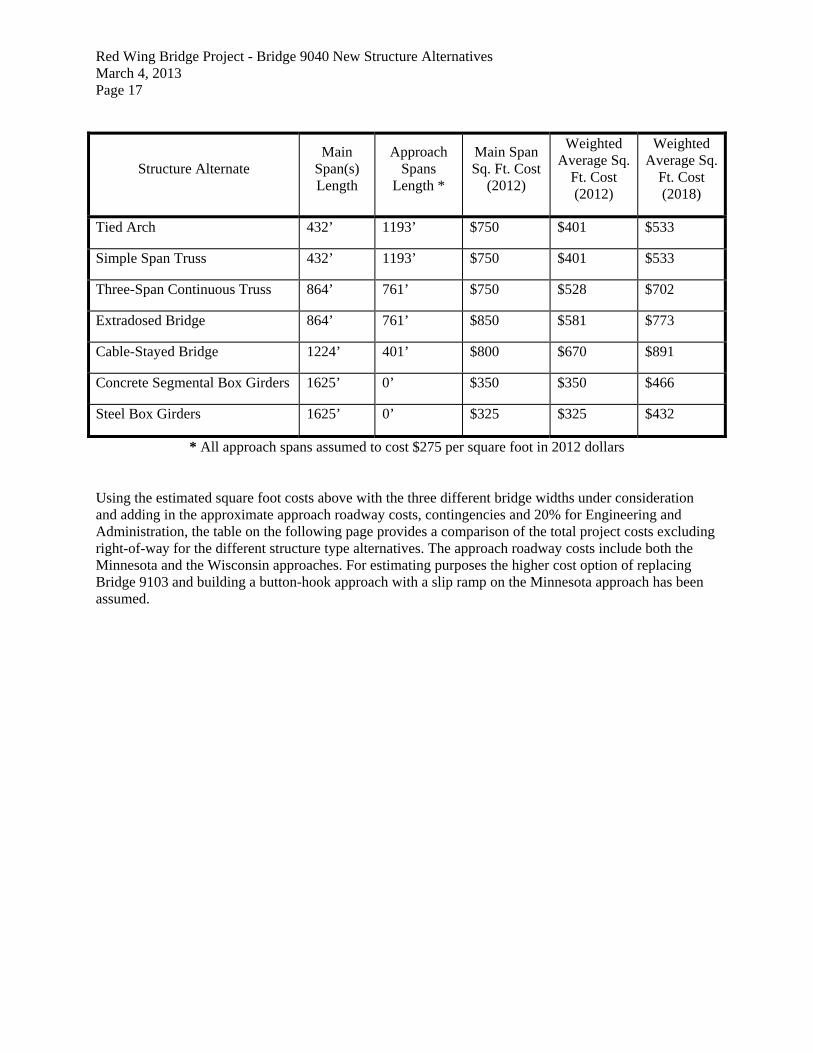
Red Wing Bridge Project - Bridge 9040 New Structure Alternatives March 4, 2013 Page 17
Structure Alternate Main
Span(s) Length
Approach Spans
Length *
Main Span Sq. Ft. Cost
(2012)
Weighted Average Sq.
Ft. Cost (2012)
Weighted Average Sq.
Ft. Cost (2018)
Tied Arch 432’ 1193’ $750 $401 $533
Simple Span Truss 432’ 1193’ $750 $401 $533
Three-Span Continuous Truss 864’ 761’ $750 $528 $702
Extradosed Bridge 864’ 761’ $850 $581 $773
Cable-Stayed Bridge 1224’ 401’ $800 $670 $891
Concrete Segmental Box Girders 1625’ 0’ $350 $350 $466
Steel Box Girders 1625’ 0’ $325 $325 $432
* All approach spans assumed to cost $275 per square foot in 2012 dollars
Using the estimated square foot costs above with the three different bridge widths under consideration and adding in the approximate approach roadway costs, contingencies and 20% for Engineering and Administration, the table on the following page provides a comparison of the total project costs excluding right-of-way for the different structure type alternatives. The approach roadway costs include both the Minnesota and the Wisconsin approaches. For estimating purposes the higher cost option of replacing Bridge 9103 and building a button-hook approach with a slip ramp on the Minnesota approach has been assumed.

Red Wing Bridge Project - Bridge 9040 New Structure Alternatives March 4, 2013 Page 18 TOTAL PROJECT COSTS INCLUDING APPROACH ROADWAY (EXCLUDING RIGHT-OF-WAY)
Structure Alternate
Total Costs for a 50’-4” Wide Bridge
(with Cost of Truss Rehab included)
Total Costs for a 60’-4” Wide, 2-Lane
Bridge
Total Costs for a 86’-1” Wide, 4-Lane
Bridge
Tied Arch $74M to $84M ($111M to $121M)
$84M to $97M $115M to $133M
Simple Span Truss $75M to $86M ($112M to $122M)
$86M to $98M $117M to $135M
Three-Span Continuous Truss
$92M to $106M ($129M to $143M)
$106M to $123M $146M to $170M
Extradosed Bridge $101M to $110M ($138M to $147M)
$117M to $128M $162M to $177M
Cable-Stayed Bridge $113M to $124M ($150M to $160M)
$132M to $144M $182M to $200M
Concrete Segmental Box Girders
$69M to $74M ($105M to $111M)
$78M to $85M $106M to $115M
Steel Box Girders $63M to $72M ($100M to $109M)
$72M to $82M $97M to $111M
- Includes Approach Roadway costs for Minnesota and Wisconsin approach, excluding right-of-way
- Approach costs assume the higher cost option of replacing Bridge 9103 and building a button-hook approach with a slip ramp
- Costs include 20% for Engineering and Administration - The 50’-4” Wide Bridge would only be built if used as part of a pair of bridges, therefore
shoulder widths assume one way traffic - The 60’-4” Wide Bridge assumes two way traffic and therefore assumes 10’ shoulders on each
side - Bridge costs include a range for contingencies to reflect material cost volatility, unknowns based
on the preliminary level of design that has been done to date, staging complexity and construction complexity
EVALUATION MATRIX
The evaluation matrix on the following page compares the seven potential structure types based on their grade raise requirements, future maintenance and inspection requirements, aesthetic impacts, the complexity of their construction, their fracture critical issues, ability to accommodate future expansion and their estimated initial construction cost. The information below is based on the discussions in the previous sections of this memo. The table provides a comparison of the alternatives in each category by ranking them “Low”, “Medium” or “High”. In all categories the “Low” ranking is the most desirable either because it has lower requirements or lower impacts or lower complexities.

Red Wing Bridge Project - Bridge 9040 New Structure Alternatives March 4, 2013 Page 19 EVALUATION MATRIX
Structure Alternate
Grade Raise Required
Future Maintenance and Inspection Requirements
Aesthetic Impacts Constructability Complexity Redundancy and Fracture
Critical Issues Difficulty of Future Expansion Other Considerations
Construction Cost per Sq. Ft. (2018)
Tied Arch
Low – 2’ +/- (Framed-in Stringers)
5’ +/- (Stacked)
Medium – Requires future painting. Inspection will require special expertise.
Low – Looks somewhat similar to existing bridge.
Medium – Bridge could be built in pieces using temporary supports, or built off-site and moved into place.
Medium – Tie girder will require special design similar to Hastings Bridge.
Medium – Original design would have to account for future addition of third arch.
Medium - $534
Simple Span Truss
Low – 2’ +/- (Framed-in Stringers)
5’ +/- (Stacked)
High – Requires future painting. Inspection will be costly.
Low – Looks similar to existing bridge.
Medium – Bridge could be built in pieces using temporary supports, or built off-site and moved into place.
High – Lower chord, tension diagonals and verticals will require special design.
Medium – Original design would have to account for future addition of third truss.
Medium - $534
Three-Span Continuous Truss
Low – 2’ +/- (Framed-in Stringers)
5’ +/- (Stacked)
High – Requires future painting. Inspection will be costly.
Low – Looks most like existing bridge.
Medium – Balanced cantilever construction of fairly light pieces.
Medium to High – Will be similar to Simple Span Truss but continuous spans will provide some additional load paths.
Medium – Original design would have to account for future addition of third truss.
Medium to High - $702
Extradosed Bridge
Medium to High – 10’ +/-
Medium – Inspection of cables and anchorages will require some special expertise.
High – Towers and grade raise will have visual impact. More modern appearance.
High – Least common structure type. Only one extradosed currently in US. Staging challenges with the required grade raise.
Low – Concrete segments are precompressed and cables are redundant at each location.
Medium to High – Original design would have to account for future addition of a third tower.
The higher grade raise requirements could add time and complexity to the construction staging and maintenance of traffic.
High - $773
Cable-Stayed Bridge
Low – 1’ +/- (Composite
Deck) 6’ +/-
(Trapezoidal Box)
Medium – Inspection of cables and anchorages will require some special expertise.
High – 300’ tall towers and modern looking cables will have the greatest visual impact.
High –300’ tall towers and installing cables will require special equipment & expertise.
Low – floor system contains multiple members or is precompressed, and cables are redundant at each location.
High – Designing cable planes and tower legs for future expansion would need to be considered in the initial design.
There may be environmental impacts due to the possible issues with migratory bird strikes with the tall towers and cables.
High - $891
Concrete Segmental Box Girders
High – 13’ +/-
Low – Concrete box girders require little maintenance and will be fairly easy to inspect.
High – 13’ Grade raise will cause a visual impact.
Medium – This type of construction has become more common. Staging challenges with the required grade raise.
Low – Concrete segments are precompressed and multiple girder lines provide redundancy.
Low – Additional box girders could be constructed to add additional lanes at a future date.
The higher grade raise requirements could add time and complexity to the construction staging and maintenance of traffic.
Low - $465
Steel Box Girders Medium to
High – 10’ +/-
Medium – Requires future painting, but will be fairly easy to inspect.
Medium to High – 10’ Grade raise will cause a visual impact.
Medium – Most common type of construction of all of the alternatives. There will be staging challenges with the required grade raise.
Low – Multiple girder lines provide redundancy.
Low – Additional box girders could be constructed to add additional lanes at a future date.
The higher grade raise requirements could add time and complexity to the construction staging and maintenance of traffic.
Low - $432
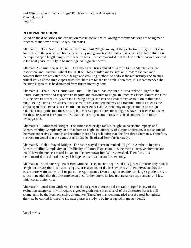
Red Wing Bridge Project - Bridge 9040 New Structure Alternatives March 4, 2013 Page 20 RECOMMENDATIONS
Based on the discussions and evaluation matrix above, the following recommendations are being made for each of the seven structure type alternates.
Alternate 1 – Tied Arch: The tied arch did not rank “High” in any of the evaluation categories. It is a good fit with the project site both aesthetically and geometrically and can be a cost effective solution in the required span length range. For these reasons it is recommended that the tied arch be carried forward to the next phase of study to be investigated in greater detail.
Alternate 2 – Simple Span Truss: The simple span truss ranked “High” in Future Maintenance and Inspection, and Fracture Critical Issues. It will look similar and be similar in cost to the tied arch, however there are not established design and detailing methods to address the redundancy and fracture critical issues of the simple span truss like there are for the tied arch. Therefore, it is recommended that the simple span truss be dismissed from future investigations.
Alternate 3 – Three-Span Continuous Truss: The three-span continuous truss ranked “High” in the Future Maintenance and Inspection category, and “Medium to High” in Fracture Critical Issues and Cost. It is the best fit aesthetically with the existing bridge and can be a cost effective solution in this span range. Being a truss, this alternate has some of the same redundancy and fracture critical issues as the simple span truss. Because it is continuous over Piers 1 and 2 there may be opportunities to design redundant load paths into the structure but MnDOT procedures for doing this have not been established. For these reasons it is recommended that the three-span continuous truss be dismissed from future investigations.
Alternate 4 – Extradosed Bridge: The extradosed bridge ranked “High” in Aesthetic Impacts and Constructability Complexity, and “Medium to High” in Difficulty of Future Expansion. It is also one of the more expensive alternates and requires more of a grade raise than the first three alternates. Therefore, it is recommended that the extradosed bridge be dismissed from further study.
Alternate 5 – Cable-Stayed Bridge: The cable-stayed alternate ranked “High” in Aesthetic Impacts, Constructability Complexity, and Difficulty of Future Expansion. It is the most expensive alternate and would have the greatest visual impact on the downtown Red Wing viewshed. Therefore, it is recommended that the cable-stayed bridge be dismissed from further study.
Alternate 6 – Concrete Segmental Box Girders: The concrete segmental box girder alternate only ranked “High” in the Aesthetic Impacts category. It is also one of the least expensive alternatives and has the least Future Maintenance and Inspection Requirements. Even though it requires the largest grade raise, it is recommended that this alternate be studied further due to its low maintenance requirements and low initial construction cost.
Alternate 7 – Steel Box Girders: The steel box girder alternate did not rank “High” in any of the evaluation categories. It will require a greater grade raise than several of the alternates but it is still estimated to be the least expensive alternative. Therefore it is recommended that the steel box girder alternate be carried forward to the next phase of study to be investigated in greater detail.
Attachments

AppendixETiedArchDetails
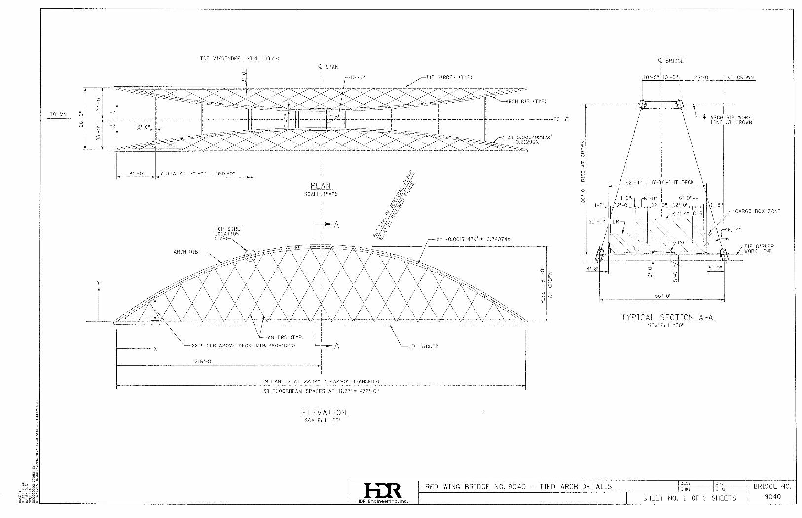


AppendixFU.S.CoastGuardClearanceEnvelopeDocuments


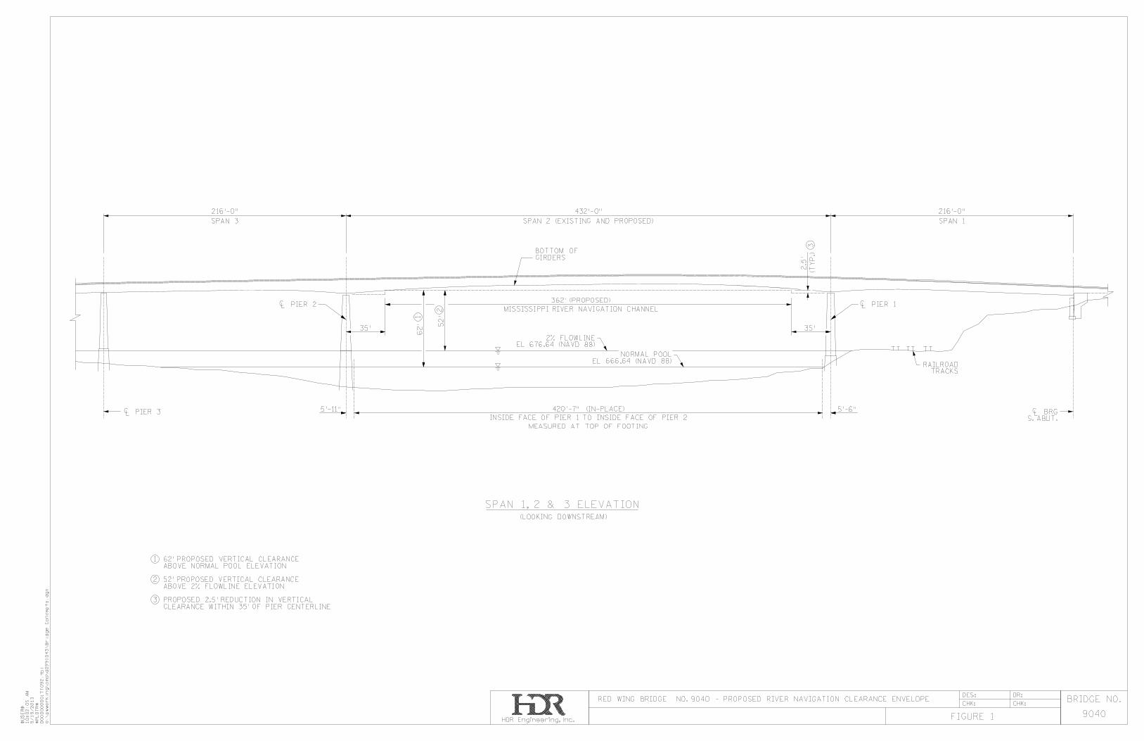

AppendixGVisualConsiderations–Bridge9040NewStructurestypes

1 of 4
GEMINI RESEARCH Susan Granger and Scott Kelly 15 East Ninth Street, Morris, MN 56267
Telephone: 320-589-3846 Fax: 320-589-1737
[email protected] MEMORANDUM TO: Chad Hanson (MnDOT D6) and Teresa Martin (MnDOT CRU) FROM: Susan Granger and Scott Kelly RE: Visual Considerations – Bridge 9040 New Structure Types DATE: January 24, 2014 The purpose of this memo is to comment on the general visual compatibility with nearby historic and scenic resources of three structure types being evaluated to potentially replace Bridge 9040. Assessing visual effects is part of MnDOT’s compliance with Section 106 of the National Historic Preservation Act, which requires that an undertaking take into consideration effects on historic properties. It is also part of Context Sensitive Design or the process of designing transportation projects that are in harmony with their community setting and preserve the value of environmental, scenic, aesthetic, historic, and natural resources. Because of its size and location, a new river bridge has the potential to have a significant impact on the character of an area rich in scenic value and historic resources. The new bridge, like Bridge 9040, will visually compete with Barn Bluff, the river itself, and man-made structures. The new bridge will be built in a setting that is largely natural. Although there are a number of industrial, commercial, and other structures nearby, the river valley is broad and a dense tree canopy, dramatic bluffs, and the wide river channel tend to dominate and to overpower the built environment from many vantage points. The new bridge will be within the viewshed of several properties that are listed on, or eligible for, the National Register of Historic Places including Barn Bluff, the Red Wing Mall Historic District (which includes Levee Park), the St. James Hotel, Burdick Grain Company Terminal Elevator, the CMSTPP Railroad Corridor Historic District, and others. The Red Wing Commercial Historic District is nearby.

2 of 4
A replacement bridge would be located immediately upstream from the existing bridge, positioning it slightly closer to historic properties such as the St. James Hotel and Levee Park and slightly farther away from Barn Bluff. To understand the potential visual impact of a new bridge on the historic and natural setting, Gemini Research looked at many photos of existing examples of each bridge type, and superimposed images of various bridges on photos of Bridge 9040 in its Red Wing setting. Gemini also studied existing Bridge 9040 to understand its visual qualities and their impact on the setting. We recommend that, in general, bridge designs that visually blend with and do not dominate the natural setting of the waterway, its forests, and its wooded bluffs are likely to be compatible with nearby historic properties. Some properties such as the St. James Hotel and Barn Bluff existed before the 1895 bridge was built; the historic integrity (i.e., character or authenticity) of their setting was diminished by the 1895 bridge and by its successor, Bridge 9040 (built in 1960). For other properties, use of the river, or a visual relationship with the river, is an important aspect of historic character; preservation of the natural setting helps preserve this aspect of historic integrity. Three types – Tied Arch, Steel Box Girder, and Concrete Segmental Box Girder – are under consideration. The remarks below focus primarily on the main and adjacent spans, which is the part of the bridge most visible from the greatest number of historic resources. All three types would have similar horizontal alignment, an overall length of about 1,625’, a main span of about 432’, and a navigation clearance of about 62’. The approach spans would likely be steel plate girder spans. While the likely number and location of piers has been identified, their form and details have not yet been explored. The piers are a significant component of bridge design and will have a strong impact on the appearance of all bridge types. Strongly modern or angular forms, for example, would likely be visually distracting and incompatible with the historic and natural setting. Piers that are overly bulky might block views of the water and trees from the perspective of viewers in Levee Park or elsewhere along the riverfront. Alternative 1: Tied Arch The tied arch bridge has a dramatic arched shape that tends to attract attention, or focus the eye onto itself. It is a visually powerful upward curve in what is essentially a wide V- or U-shaped river valley. The arch visually competes with, or pulls attention away from, the river corridor and Barn Bluff. The arch is a shape not reflected in any of the landforms nearby.

3 of 4
While the deck of the tied arch brick would be fairly shallow (about 5’ deep over the main river piers), the bridge would have a considerable amount of structure above the deck to both attract attention and block views of the setting. For comparison, at 80’ tall the top of the arch would be about 50% higher than the top of the current bridge’s truss. The steel in the tied arch would also be thick or bulky – about 3’ x 4’ in section. The current bridge’s truss structure, on the other hand, is built of more slender metal and tends to be more visually translucent. From an on-deck perspective, the tied arch’s large above-deck structure would tend to dominate the user’s experience and block views of the river and bluffs. Many tied arch bridges are designed with highly-modern shapes and design references that would not be compatible with nearby historic resources, although the design could be made more compatible by avoiding these shapes. At 59’ wide between tie girders, the bridge would be somewhat wider than other types. The steel on the bridge could be painted a dark color to help it visually recede somewhat. The shape of the piers would significantly affect the design. Alternative 2: Steel Box Girder The steel box girder bridge would be about 12’ deep over the main river piers, which would be thicker than the tied arch’s 5’ depth but more slender than the concrete segmental box girder. The steel box girder would lack structure above the deck (depending on how the piers were treated) and instead appear from a distance as a largely horizontal line. This shape would be more compatible with horizontal landforms and the wide V- or U-shaped river corridor. Rather than blocking a significant part of the natural setting it would tend to visually open up the view. The lack of an above-deck structure would also provide open views from the perspective of a vehicle or user on top of the deck. The steel could be painted a dark color, which would visually slim the deck and reduce some of the “bulk” of the structure. This type of bridge has perhaps the greatest potential to be made visually compatible with the setting, particularly if traditional shapes are used rather than overly stylized forms or highly modern design references. The shape of the piers will have a major effect on the bridge’s appearance and visual impact. Alternative 3: Concrete Segmental Box Girder The concrete segmental box girder bridge would have a deeper deck structure – up to 21’ over the piers – that would make it bulky and more visually obtrusive than the steel box girder. Staining the concrete a dark color would help visually slim the

4 of 4
bridge, but there is a limit to how dark the concrete could be colored. (A darker color would likely be achieved with a steel box girder bridge.) The lack of structure above the deck and the largely horizontal line created by the bridge would open up the view and allow more of the river corridor’s bluffs and trees to be experienced. The lack of an above-deck structure would also open up the view from the perspective of a vehicle or user on top of the deck. The degree to which the concrete segmental box girder bridge harmonizes with the scenic, historic river corridor would depend on the design’s shapes and detailing. As with the other types, the design of the piers, for example, would have a major effect on the bridge’s appearance and visual impact.

AppendixHSupplementalWebDepthStudy
C:\Users\dcoletti\Documents\1_HDR Projects\MN Projects\RedWing\Steel Box Girder Concept Evaluation\Flagsheet_ALL.xlsm
1.7 Post 3-21-14 MnDOT Meeting Study
Red Wing Bridge (No. 9040)CLIENT: Mn/DOT
HDR Project Number: 177092
Steel Box Girder Concept Study
C:\Users\dcoletti\Documents\1_HDR Projects\MN Projects\RedWing\Steel Box Girder Concept Evaluation\Flagsheet_ALL.xlsm
1.7 Post 3-21-14 MnDOT Meeting Study
1.7.1 Introduction
Red Wing Bridge (No. 9040)CLIENT: Mn/DOT
HDR Project Number: 177092
Steel Box Girder Concept Study

Red Wing Bridge Post 3-21-14 MnDOT Meeting Study Steel Box Girder Option Page 1 of 3
Red Wing Bridge Concept Evaluation Report Steel Box Girder Discussion STUDY AFTER 3-21-14 MEETING WITH MnDOT On 3-21-14, HDR met with MnDOT to discuss the studies completed to date. As a result of discussions at that meeting, a supplemental study was performed to investigate the following option:
• Maximum web depth (at Piers 1 and 2) = 13’-6” • Minimum web depth (South Abutment, Midspan of Span 2, Pier 3) = 8’-6” • Span Arrangement: 216’ – 432’ – 266’ (i.e., Span 3 50’ longer than originally studied)
This option was designated Option 13. The maximum and minimum web depths were selected to correspond to a structure depth that would result in profile grade changes on the Wisconsin approach roadway which were considered acceptable (minimal). The revised span arrangement was selected to investigate the effects of a longer end span for the three span unit. The length of Span 1 could not be adjusted since the location of the South Abutment is constrained by high rock at the site, and since the location of Pier 1 is constrained by the presence of the railroad and by navigational clearances. The position of Pier 2 is also constrained by navigational clearances. However, moving Pier 3 further north allows for a longer Span 3 (to better balance Span 2) and also allows for shortening of Spans 4, 5, 6, 7, and 8 by 10’ each, which should allow the use of more economical, lighter weight 63” precast, prestressed girders (instead of the 82” deep precast, prestressed girders originally proposed for these spans). In Option 13, all flange widths were adjusted to optimize the design for the given web depths and span arrangements. In addition, the widths of the top flanges in Spans 1 and 3 were narrowed to a more economical 24” rather than the uniform 30” plus previously investigated. As a result, Option 13 now has the lowest LB/SF weight of steel in Spans 1 and 3, and one of the lowest LB/SF weights of steel in Span 2. Option 13 also has the lowest cost of structural steel on a $/SF basis. Keep in mind, the previous options did not have their top flange widths optimized in Spans 1 and 3, so this is not a completely fair comparison. The analysis considered both HL-93 live load, and also the MnDOT P413 vehicle. Live load deflections were investigated, but only for the HL-93 live load case. The calculated live load deflection for the HL-93 live load case for Span 2 (controlling span) was 4.65”, vs. an allowable deflection of 5.2” based on L/1000. Note that the calculated live load deflection was determined from a line girder analysis, using the AASHTO empirical live load distribution

Red Wing Bridge Post 3-21-14 MnDOT Meeting Study Steel Box Girder Option Page 2 of 3
factors. In final design, using a refined analysis, and using a more correct interpretation of the live load deflection provisions, a lower calculated deflection would be expected, so the current analysis should be conservative. It should be noted that the overall these Concept Evaluation Report design studies were based on simplified line girder analysis, using the AASHTO empirical live load distribution factors, and not examining web design in detail. Future design efforts should include more refined analysis methods, including methods which allow for refined evaluation of live load distribution through relative stiffness analysis, and should also include a more detailed evaluation of the web design. It should also be noted that the range of structural steel costs among the nine options examined varied by only 6% between a maximum cost of $10.8 million and $10.2 million. Given the approximate nature of this preliminary design study, this is a very tight range, indicating that a relatively economical design could be produced from any of a number of these girder depth options. It should also be noted that there are several detailed differences in the designs which could further affect the pricing of the final design. For instance, all designs featured the use of Grade 70 steel in a hybrid Grade 50/Grade 70 design configuration, as illustrated in the table below:
Location Steel Grade Webs Grade 50 Top Flanges, Positive Moment Regions Grade 50 Top Flanges, Negative Moment Regions Grade 70 Bottom Flanges Grade 70 Stiffeners, Diaphragms, Top Flange Lateral Bracing, etc. Grade 50
The price of Grade 70 steel is often a function of the plate thickness, which affects availability as some US mills are limited to rolling Grade 70 steel only up to a maximum thickness (traditionally 2”). Several of the girder depth options were able to achieve a successful design using a maximum flange thickness of 2” or less in all of the Grade 70 flanges. This would potentially further reduce the relative cost of these options. A summary of maximum thickness of Grade 70 flanges for each option was provided in a previous report. For Option 13, the maximum thickness of any Grade 70 flanges was 1 ¾”. Other considerations may also affect the final selection of girder minimum and maximum depth, including aesthetics. Input from an experienced bridge architect would be valuable in defining the parameters of an aesthetically pleasing profile for the parabolic haunch of the variable depth box girders. As noted above, the various minimum and maximum depth girder combinations considered in this study did not exhibit a wide range of final costs, suggesting that reasonable consideration of aesthetics in the determination of the final girder depths should not result in a significant adverse impact on the final cost of the structure.
Red Wing Bridge Post 3-21-14 MnDOT Meeting Study Steel Box Girder Option Page 3 of 3
In summary, the analysis of Option 13, with a 13’-6” maximum web depth, an 8’-6” minimum web depth, and a span arrangement of 216’ – 432’ – 266’, suggests this option would be preferred over previously investigated options for the steel box girder unit for the Red Wing Bridge. During the final design phase it would be prudent to undertake a reasonable amount of further study, preferably using a more refined analysis method, to determine the most optimum design parameters, considering aesthetic as well as more detailed structural design considerations.

C:\Users\dcoletti\Documents\1_HDR Projects\MN Projects\RedWing\Steel Box Girder Concept Evaluation\Flagsheet_ALL.xlsm
1.7 Post 3-21-14 MnDOT Meeting Study
1.7.2 Design Summaries
Red Wing Bridge (No. 9040)CLIENT: Mn/DOT
HDR Project Number: 177092
Steel Box Girder Concept Study

C:\Users\dcoletti\Documents\1_HDR Projects\MN Projects\RedWing\Steel Box Girder Concept Evaluation\Flagsheet_ALL.xlsm
1.7 Post 3-21-14 MnDOT Meeting Study1.7.2 Design Summaries
1.7.2.1 Option 13, Web Depth = 13'-6" (Max), 8'-6" (Min)
Red Wing Bridge (No. 9040)CLIENT: Mn/DOT
HDR Project Number: 177092
Steel Box Girder Concept Study

RW-TubStudy.xlsSTLBRIDGE Run Log Page 1 of 1
Date Printed: 3/24/20142:59 PM
Project: Red Wing Bridge No. 9040 Computed: DAC Date: 3/24/2014Subject: Steel Box Girder Concept Study Checked: Date:Task: Page: of:Job #: No:
STLBRIDGE RUN LOG
RW-SB-01 Initial run. File corrupted and abandoned
RW-SB-02 Rebuild of Run 01. File corrupted and abandoned.
RW-SB-03 Option 1, 12'-0" Max Web Depth, 6'-0" Min Web Depth Does not pass LL Defl Criteria
RW-SB-04 Option 2, 12'-0" Max Web Depth, 7'-0" Min Web Depth Passes LL Defl Criteria
RW-SB-05 Option 4, 12'-0" Max Web Depth, 8'-0" Min Web Depth Passes LL Defl Criteria comfortably
RW-SB-06 Option 3, 12'-0" Max Web Depth, 7'-6" Min Web Depth Passes LL Defl Criteria
RW-SB-07 Option 7, 13'-0" Max Web Depth, 7'-6" Min Web Depth Passes LL Defl Criteria NEW
RW-SB-08 Option 8, 14'-0" Max Web Depth, 7'-6" Min Web Depth Passes LL Defl Criteria NEW
RW-SB-09 Option 9, 15'-0" Max Web Depth, 7'-6" Min Web Depth Passes LL Defl Criteria NEW
RW-SB-10 Option 10, 13'-0" Max Web Depth, 8'-0" Min Web Depth Passes LL Defl Criteria NEW
RW-SB-11 Option 11, 14'-0" Max Web Depth, 8'-6" Min Web Depth Passes LL Defl Criteria NEW
RW-SB-12 Option 12, 15'-0" Max Web Depth, 9'-0" Min Web Depth Passes LL Defl Criteria NEW
000000000177092

RW-TubStudy.xlsFlg&Web Dim 8'-6" to 13'-6" Page 1 of 5
Date Printed: 3/24/20142:59 PM
Project: Red Wing Bridge No. 9040 Computed: DAC Date: 3/24/2014Subject: Steel Box Girder Concept Study Checked: Date:Task: Page: of:Job #: No:
Haunched Girder Web and Flange Dimensions
Determine web depths and flange widths at increments along length of span to model haunched girder in STLBRIDGE
Span 1 Web Depths for Web Plate Input (STLBRIDGE is limited to 8 web sections per span)
y=kx2 k = 0.00052062 Web slope = 5.7857Min Web Depth = 8.5 ft Bot Flange Proj past Web= 2.00 inMax Web Depth = 13.5 ft Box Width at Top (C-C Webs) = 116.00 in
Height of parabola, y = 5 ftLength of parabola, x = 98 ft
Position Dist., x Ord., y Slope θ θ Web Depth bbf bbf-avg
ft ft ft ft/ft Rad Deg in in in
Assume constant depth from end of span to first position listed below
118 0 0.00 102.0 84.5
14 0.007 0.007 0.42 84.5
132 14 0.10 103.2 84.5
14 0.022 0.022 1.25 83.8
146 28 0.41 106.9 83.0
14 0.036 0.036 2.09 82.0
160 42 0.92 113.0 81.0
14 0.051 0.051 2.92 79.5
174 56 1.63 121.6 78.0
14 0.066 0.066 3.75 76.0
188 70 2.55 132.6 74.0
14 0.080 0.080 4.58 71.8
202 84 3.67 146.1 69.5
14 0.095 0.094 5.41 66.8
216 98 5.00 162.0 64.0
000000000177092

RW-TubStudy.xlsFlg&Web Dim 8'-6" to 13'-6" Page 2 of 5
Date Printed: 3/24/20142:59 PM
Project: Red Wing Bridge No. 9040 Computed: DAC Date: 3/24/2014Subject: Steel Box Girder Concept Study Checked: Date:Task: Page: of:Job #: No:
Haunched Girder Web and Flange Dimensions
Determine web depths and flange widths at increments along length of span to model haunched girder in STLBRIDGE
000000000177092
Span 2 Web Depths for Web Plate Input (STLBRIDGE is limited to 8 web sections per span)
y=kx2 k = 0.00022222 Web slope = 5.7857Min Web Depth = 8.5 ft Bot Flange Proj past Web= 2.00 inMax Web Depth = 13.5 ft Box Width at Top (C-C Webs) = 116.00 in
Height of parabola, y = 5 ftLength of parabola, x = 150 ft
Position Dist., x Ord., y Slope θ θ Web Depth bbf bbf-avg
ft ft ft ft/ft Rad Deg in in in
Assume constant depth from end of span to first position listed below
0 150 5.00 162.0 64.0
50 0.056 0.055 3.18 69.8
50 100 2.22 128.7 75.5
50 0.033 0.033 1.91 79.0
100 50 0.56 108.7 82.5
50 0.011 0.011 0.64 83.5
150 0 0.00 102.0 84.5
132 Assume constant depth web in this region 84.5
282 0 0.00 102.0 84.5
50 0.011 0.011 0.64 83.5
332 50 0.56 108.7 82.5
50 0.033 0.033 1.91 79.0
382 100 2.22 128.7 75.5
50 0.056 0.055 3.18 69.8
432 150 5.00 162.0 64.0
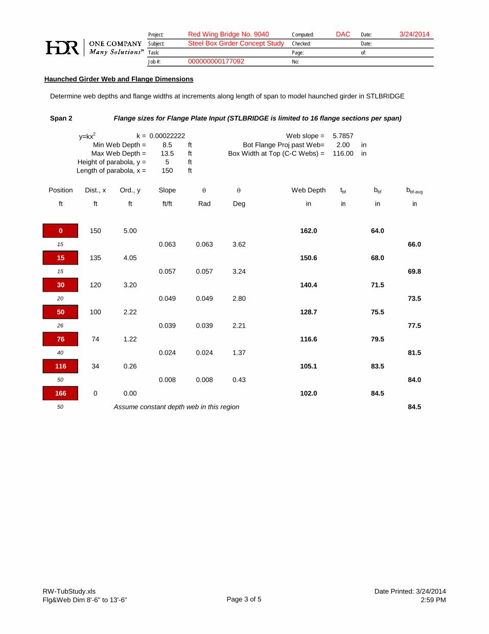
RW-TubStudy.xlsFlg&Web Dim 8'-6" to 13'-6" Page 3 of 5
Date Printed: 3/24/20142:59 PM
Project: Red Wing Bridge No. 9040 Computed: DAC Date: 3/24/2014Subject: Steel Box Girder Concept Study Checked: Date:Task: Page: of:Job #: No:
Haunched Girder Web and Flange Dimensions
Determine web depths and flange widths at increments along length of span to model haunched girder in STLBRIDGE
000000000177092
Span 2 Flange sizes for Flange Plate Input (STLBRIDGE is limited to 16 flange sections per span)
y=kx2 k = 0.00022222 Web slope = 5.7857Min Web Depth = 8.5 ft Bot Flange Proj past Web= 2.00 inMax Web Depth = 13.5 ft Box Width at Top (C-C Webs) = 116.00 in
Height of parabola, y = 5 ftLength of parabola, x = 150 ft
Position Dist., x Ord., y Slope θ θ Web Depth tbf bbf bbf-avg
ft ft ft ft/ft Rad Deg in in in in
0 150 5.00 162.0 64.0
15 0.063 0.063 3.62 66.0
15 135 4.05 150.6 68.0
15 0.057 0.057 3.24 69.8
30 120 3.20 140.4 71.5
20 0.049 0.049 2.80 73.5
50 100 2.22 128.7 75.5
26 0.039 0.039 2.21 77.5
76 74 1.22 116.6 79.5
40 0.024 0.024 1.37 81.5
116 34 0.26 105.1 83.5
50 0.008 0.008 0.43 84.0
166 0 0.00 102.0 84.5
50 Assume constant depth web in this region 84.5

RW-TubStudy.xlsFlg&Web Dim 8'-6" to 13'-6" Page 4 of 5
Date Printed: 3/24/20142:59 PM
Project: Red Wing Bridge No. 9040 Computed: DAC Date: 3/24/2014Subject: Steel Box Girder Concept Study Checked: Date:Task: Page: of:Job #: No:
Haunched Girder Web and Flange Dimensions
Determine web depths and flange widths at increments along length of span to model haunched girder in STLBRIDGE
000000000177092
Span 2 (cont) Flange sizes for Flange Plate Input (STLBRIDGE is limited to 16 flange sections per span)
Position Dist., x Ord., y Slope θ θ Web Depth tbf bbf bbf-avg
ft ft ft ft/ft Rad Deg in in in in
216 0 0.00 102.0 84.5
50 15 Assume constant depth web in this region 84.5
266 0 0.00 102.0 84.5
50 0.008 0.008 0.43 84.0
316 34 0.26 105.1 83.5
40 0.024 0.024 1.37 81.5
356 74 1.22 116.6 79.5
26 0.039 0.039 2.21 77.5
382 100 2.22 128.7 75.5
20 0.049 0.049 2.80 73.5
402 120 3.20 140.4 71.5
15 0.057 0.057 3.24 69.8
417 135 4.05 150.6 68.0
15 0.063 0.063 3.62 66.0
432 150 5.00 162.0 64.0

RW-TubStudy.xlsFlg&Web Dim 8'-6" to 13'-6" Page 5 of 5
Date Printed: 3/24/20142:59 PM
Project: Red Wing Bridge No. 9040 Computed: DAC Date: 3/24/2014Subject: Steel Box Girder Concept Study Checked: Date:Task: Page: of:Job #: No:
Haunched Girder Web and Flange Dimensions
Determine web depths and flange widths at increments along length of span to model haunched girder in STLBRIDGE
000000000177092
Span 3 Web Depths for Web Plate Input (STLBRIDGE is limited to 8 web sections per span)
Symmetrical to Span 1, except that span length may be increased by 50'

Project: Red Wing Bridge Computed: DAC Date: 3-24-14 Subject: Steel Box Girder Study Checked: Date:
Task: STLBRIDGE Results Page: of:
Job #: 000000000177092 No:
c:\users\dcoletti\documents\1_hdr projects\mn projects\redwing\post mndot 3-21-14 mtg\rw 13_stlbridge.doc Date Printed: 3/24/2014
STLBRIDGE Summaries
8’-6” Minimum Web Depth, 13’-6” Max Web Depth, HL 93 Loading
Span 1

Project: Red Wing Bridge Computed: DAC Date: 3-24-14 Subject: Steel Box Girder Study Checked: Date:
Task: STLBRIDGE Results Page: of:
Job #: 000000000177092 No:
c:\users\dcoletti\documents\1_hdr projects\mn projects\redwing\post mndot 3-21-14 mtg\rw 13_stlbridge.doc Date Printed: 3/24/2014
STLBRIDGE Summaries
8’-6” Minimum Web Depth, 13’-6” Max Web Depth, HL 93 Loading
Span 2

Project: Red Wing Bridge Computed: DAC Date: 3-24-14 Subject: Steel Box Girder Study Checked: Date:
Task: STLBRIDGE Results Page: of:
Job #: 000000000177092 No:
c:\users\dcoletti\documents\1_hdr projects\mn projects\redwing\post mndot 3-21-14 mtg\rw 13_stlbridge.doc Date Printed: 3/24/2014
STLBRIDGE Summaries
8’-6” Minimum Web Depth, 13’-6” Max Web Depth, HL 93 Loading
Span 3

Project: Red Wing Bridge Computed: DAC Date: 3-24-14 Subject: Steel Box Girder Study Checked: Date:
Task: STLBRIDGE Results Page: of:
Job #: 000000000177092 No:
c:\users\dcoletti\documents\1_hdr projects\mn projects\redwing\post mndot 3-21-14 mtg\rw 13_stlbridge.doc Date Printed: 3/24/2014
STLBRIDGE Summaries
8’-6” Minimum Web Depth, 13’-6” Max Web Depth, P413 Loading
Span 1
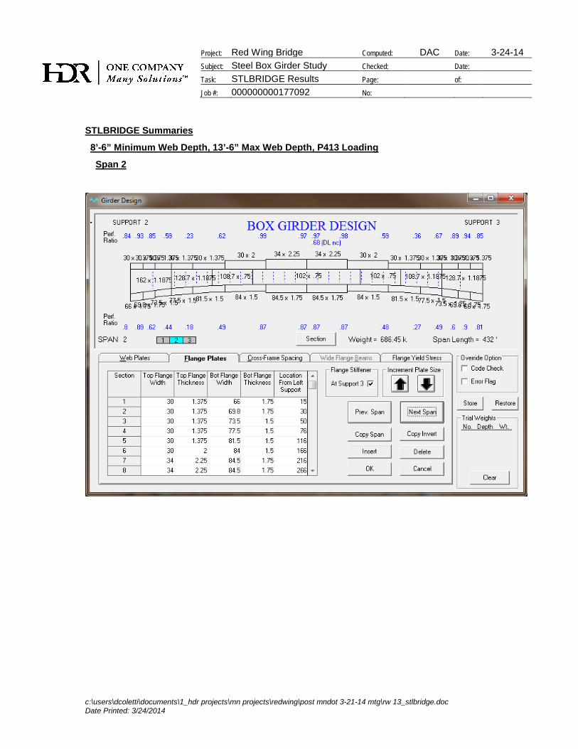
Project: Red Wing Bridge Computed: DAC Date: 3-24-14 Subject: Steel Box Girder Study Checked: Date:
Task: STLBRIDGE Results Page: of:
Job #: 000000000177092 No:
c:\users\dcoletti\documents\1_hdr projects\mn projects\redwing\post mndot 3-21-14 mtg\rw 13_stlbridge.doc Date Printed: 3/24/2014
STLBRIDGE Summaries
8’-6” Minimum Web Depth, 13’-6” Max Web Depth, P413 Loading
Span 2
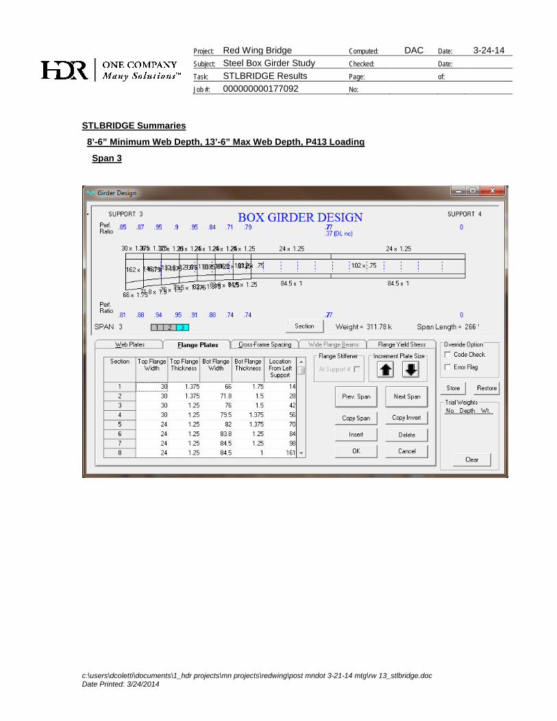
Project: Red Wing Bridge Computed: DAC Date: 3-24-14 Subject: Steel Box Girder Study Checked: Date:
Task: STLBRIDGE Results Page: of:
Job #: 000000000177092 No:
c:\users\dcoletti\documents\1_hdr projects\mn projects\redwing\post mndot 3-21-14 mtg\rw 13_stlbridge.doc Date Printed: 3/24/2014
STLBRIDGE Summaries
8’-6” Minimum Web Depth, 13’-6” Max Web Depth, P413 Loading
Span 3

C:\Users\dcoletti\Documents\1_HDR Projects\MN Projects\RedWing\Steel Box Girder Concept Evaluation\Flagsheet_ALL.xlsm
1.7 Post 3-21-14 MnDOT Meeting Study
1.7.3 Weight Summaries
Red Wing Bridge (No. 9040)CLIENT: Mn/DOT
HDR Project Number: 177092
Steel Box Girder Concept Study
C:\Users\dcoletti\Documents\1_HDR Projects\MN Projects\RedWing\Steel Box Girder Concept Evaluation\Flagsheet_ALL.xlsm
1.7 Post 3-21-14 MnDOT Meeting Study1.7.3 Weight Summaries
1.7.3.1 Option 13, Web Depth = 13'-6" (Max), 8'-6" (Min)
Red Wing Bridge (No. 9040)CLIENT: Mn/DOT
HDR Project Number: 177092
Steel Box Girder Concept Study
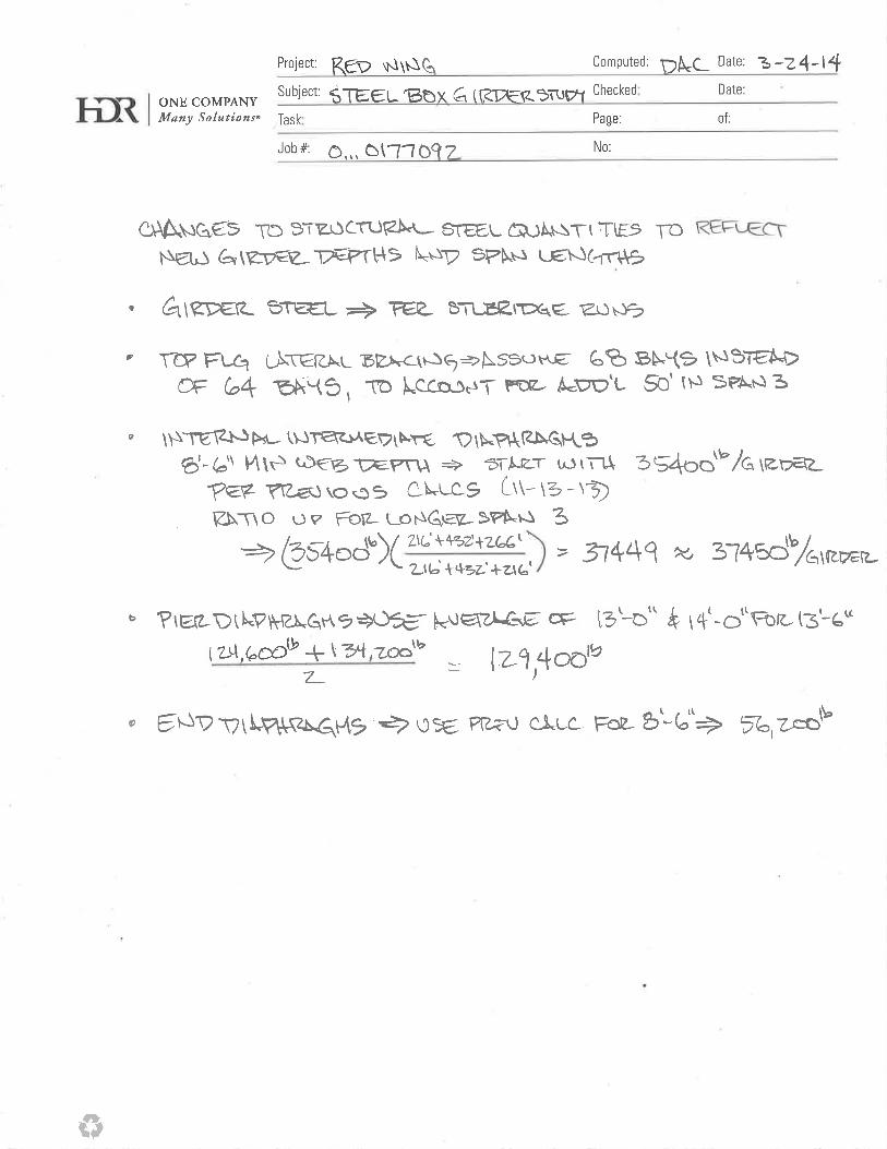

Tub Weight-RW.xls3-24-14 SUMMARY Page 1 of 1
Date Printed: 3/24/20143:01 PM
Project: Red Wing Bridge No. 9040 Computed: DAC Date: 3/24/2014Subject: Steel Box Girder Concept Study Checked: Date:Task: Page: of:Job #: No:
Estimated Weight of Structural SteelSummary
$/LBGr 50 Girder Steel 1.60$ 61% of girder steel is Gr 50 Weighted Average Unit Cost of Girder Steel 1.87$ Gr 70 Girder Steel 2.30$ 39% of girder steel is Gr 70
Gr 50 Detail Steel 3.20$
Option 2 Option 3 Option 4 Option 7 Option 8 Option 9 Option 10 Option 11 Option 12 Option 1312'-0" (Max) 12'-0" (Max) 12'-0" (Max) 13'-0" (Max) 14'-0" (Max) 15'-0" (Max) 13'-0" (Max) 14'-0" (Max) 15'-0" (Max) 13'-6" (Max)7'-0" (Min) 7'-6" (Min) 8'-0" (Min) 7'-6" (Min) 7'-6" (Min) 7'-6" (Min) 8'-0" (Min) 8'-6" (Min) 9'-0" (Min) 8'-6" (Min)
Total Weight of "Detail Steel" (entire bridge) = 811,300 LB 810,600 LB 817,900 LB 812,100 LB 827,200 LB 838,500 LB 816,600 LB 836,100 LB 858,200 LB 858,800 LBCost of Detail Steel (entire bridge) = 2,596,160$ 2,593,920$ 2,617,280$ 2,598,720$ 2,647,040$ 2,683,200$ 2,613,120$ 2,675,520$ 2,746,240$ 2,748,160$
Minimum
Total Weight of Girders (entire bridge) = 4,391,900 LB 4,244,200 LB 4,272,800 LB 4,062,500 LB 4,154,100 LB 4,168,100 LB 4,036,500 LB 4,100,400 LB 4,222,000 LB 4,146,900 LBCost of Girders Steel (entire bridge) = 8,226,029$ 7,949,387$ 8,002,954$ 7,609,063$ 7,780,629$ 7,806,851$ 7,560,365$ 7,680,049$ 7,907,806$ 7,767,144$
Minimum
Total Weight of Structural Steel (entire bridge) = 5,203,200 LB 5,054,800 LB 5,090,700 LB 4,874,600 LB 4,981,300 LB 5,006,600 LB 4,853,100 LB 4,936,500 LB 5,080,200 LB 5,005,700 LBTotal Cost of Structural Steel (entire bridge) = 10,822,189$ 10,543,307$ 10,620,234$ 10,207,783$ 10,427,669$ 10,490,051$ 10,173,485$ 10,355,569$ 10,654,046$ 10,515,304$
Minimum
Total Deck Area = 45216 SF 45216 SF 45216 SF 45216 SF 45216 SF 45216 SF 45216 SF 45216 SF 45216 SF 47832 SFCost per SF = 239.35$ /SF 233.18$ /SF 234.88$ /SF 225.76$ /SF 230.62$ /SF 232.00$ /SF 225.00$ /SF 229.03$ /SF 235.63$ /SF 219.84$ /SF
Minimum
LB Structural Steel per SF of Deck, 216' Span = 90.1 LB/SF 86.1 LB/SF 89.5 LB/SF 84.9 LB/SF 87.1 LB/SF 88.9 LB/SF 85.9 LB/SF 87.6 LB/SF 93.3 LB/SF 82.8 LB/SFMinimum
LB Structural Steel per SF of Deck, 432' Span = 119.2 LB/SF 117.2 LB/SF 115.2 LB/SF 111.1 LB/SF 113.2 LB/SF 112.4 LB/SF 109.3 LB/SF 110.9 LB/SF 111.0 LB/SF 110.0 LB/SFMinimum
LB Structural Steel per SF of Deck, 266' Span = 81.1 LB/SF
LB Structural Steel per SF of Deck, Overall = 115.1 LB/SF 111.8 LB/SF 112.6 LB/SF 107.8 LB/SF 110.2 LB/SF 110.7 LB/SF 107.3 LB/SF 109.2 LB/SF 112.4 LB/SF 104.7 LB/SFMinimum
For Comparison
Lafayette Bridge Bridge No. 62017 Bridge No. 62018 Maximum Cost 10,822,189$ Minimum Cost 10,173,485$
Deck Area = 231,634 SF 196,685 SF Difference 648,704$ Difference 6.4%
Total Weight of Structural Steel = 14,953,256 LB 13,861,466 LB
LB Structural Steel per SF of Deck, Overall = 64.6 LB/SF 70.5 LB/SF
Assume Red Wing Estimate is conservative due to contingency factors and approximate analysisCompare Option 13
If 10% Cons If 15% Cons If 20% Cons
LB Structural Steel per SF of Deck, 216' Span = 75.3 LB/SF 72.0 LB/SF 69.0 LB/SF
LB Structural Steel per SF of Deck, 432' Span = 100.0 LB/SF 95.6 LB/SF 91.6 LB/SF
LB Structural Steel per SF of Deck, 266' Span = 73.7 LB/SF 70.5 LB/SF 67.6 LB/SF
LB Structural Steel per SF of Deck, Overall = 95.1 LB/SF 91.0 LB/SF 87.2 LB/SF
000000000177092
(Note: A "Contingency" of 10% will be applied to the final superstrucure cost estimate.)
Considering the differences in main span lengths (362' for Layfayette, 432' for Red Wing) and span balance (Red Wing is not optimal), the Red Wing estimate compares reasonably well to the Lafayette values

Tub Weight-RW.xls8'-6" to 13'-6" Page 1 of 3
Date Printed: 3/24/20143:01 PM
Project: Red Wing Bridge No. 9040 Computed: DAC Date: 3/24/2014Subject: Steel Box Girder Concept Study Checked: Date:Task: Page: of:Job #: No:
Estimated Weight of Structural Steel8'-6" Minimum Web Depth, 13'-6" Maximum Web Depth (Option 13)
Top Flange Lateral Bracing (TFLB)
Length of Strut (see separate calcs) = 9.50'
Length of Diagonal (see separate calcs) = 16.50'
Number of Bays per Girder (see separate calcs) = 68
Assumed Weight of TFLB Struts (see separate calcs) = 38.9 LB/ft
Assumed Weight of TFLB Diagonals (see separate calcs) = 65.0 LB/ft
Raw Weight of TFLB (one girder) = 98,059 LB
% Increase for Connections, Design Uncertainty, etc. = 10%
Weight of TFLB (one girder) = 107,866 LB
Number of Girders = 3
Weight of TFLB (entire bridge) = 323,600 LB
Internal Intermediate Diaphragms
Weight of Internal Intermediate Diaphragms, One Girder Line (see separate calcs) = 37,450 LB
% Increase for Connections, Design Uncertainty, etc. = 10%
Weight of Internal Intermediate Diaphragms (one girder) = 41,195 LB
Number of Girders = 3
Weight of Int Intmd Diaphragms (entire bridge) = 123,600 LB
000000000177092
(Note: A "Contingency" of 10% will be applied to the final superstrucure cost estimate.)
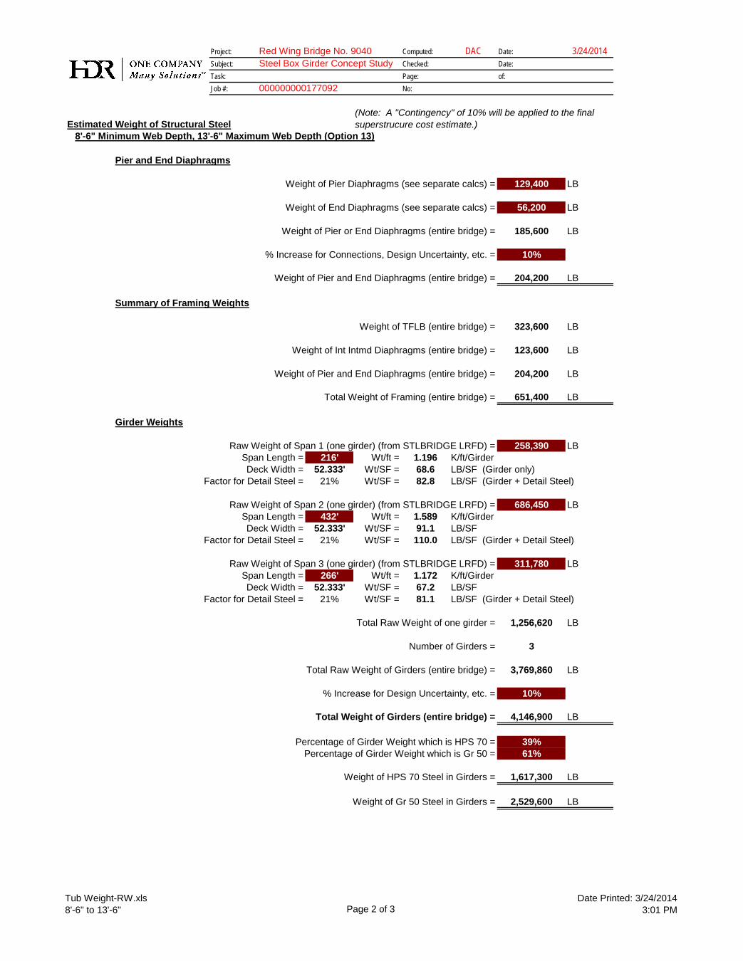
Tub Weight-RW.xls8'-6" to 13'-6" Page 2 of 3
Date Printed: 3/24/20143:01 PM
Project: Red Wing Bridge No. 9040 Computed: DAC Date: 3/24/2014Subject: Steel Box Girder Concept Study Checked: Date:Task: Page: of:Job #: No:
Estimated Weight of Structural Steel8'-6" Minimum Web Depth, 13'-6" Maximum Web Depth (Option 13)
000000000177092
(Note: A "Contingency" of 10% will be applied to the final superstrucure cost estimate.)
Pier and End Diaphragms
Weight of Pier Diaphragms (see separate calcs) = 129,400 LB
Weight of End Diaphragms (see separate calcs) = 56,200 LB
Weight of Pier or End Diaphragms (entire bridge) = 185,600 LB
% Increase for Connections, Design Uncertainty, etc. = 10%
Weight of Pier and End Diaphragms (entire bridge) = 204,200 LB
Summary of Framing Weights
Weight of TFLB (entire bridge) = 323,600 LB
Weight of Int Intmd Diaphragms (entire bridge) = 123,600 LB
Weight of Pier and End Diaphragms (entire bridge) = 204,200 LB
Total Weight of Framing (entire bridge) = 651,400 LB
Girder Weights
Raw Weight of Span 1 (one girder) (from STLBRIDGE LRFD) = 258,390 LBSpan Length = 216' Wt/ft = 1.196 K/ft/GirderDeck Width = 52.333' Wt/SF = 68.6 LB/SF (Girder only)
Factor for Detail Steel = 21% Wt/SF = 82.8 LB/SF (Girder + Detail Steel)
Raw Weight of Span 2 (one girder) (from STLBRIDGE LRFD) = 686,450 LBSpan Length = 432' Wt/ft = 1.589 K/ft/GirderDeck Width = 52.333' Wt/SF = 91.1 LB/SF
Factor for Detail Steel = 21% Wt/SF = 110.0 LB/SF (Girder + Detail Steel)
Raw Weight of Span 3 (one girder) (from STLBRIDGE LRFD) = 311,780 LBSpan Length = 266' Wt/ft = 1.172 K/ft/GirderDeck Width = 52.333' Wt/SF = 67.2 LB/SF
Factor for Detail Steel = 21% Wt/SF = 81.1 LB/SF (Girder + Detail Steel)
Total Raw Weight of one girder = 1,256,620 LB
Number of Girders = 3
Total Raw Weight of Girders (entire bridge) = 3,769,860 LB
% Increase for Design Uncertainty, etc. = 10%
Total Weight of Girders (entire bridge) = 4,146,900 LB
Percentage of Girder Weight which is HPS 70 = 39%Percentage of Girder Weight which is Gr 50 = 61%
Weight of HPS 70 Steel in Girders = 1,617,300 LB
Weight of Gr 50 Steel in Girders = 2,529,600 LB
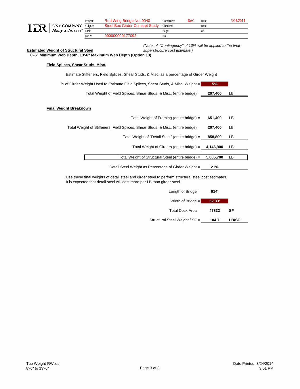
Tub Weight-RW.xls8'-6" to 13'-6" Page 3 of 3
Date Printed: 3/24/20143:01 PM
Project: Red Wing Bridge No. 9040 Computed: DAC Date: 3/24/2014Subject: Steel Box Girder Concept Study Checked: Date:Task: Page: of:Job #: No:
Estimated Weight of Structural Steel8'-6" Minimum Web Depth, 13'-6" Maximum Web Depth (Option 13)
000000000177092
(Note: A "Contingency" of 10% will be applied to the final superstrucure cost estimate.)
Field Splices, Shear Studs, Misc.
Estimate Stiffeners, Field Splices, Shear Studs, & Misc. as a percentage of Girder Weight
% of Girder Weight Used to Estimate Field Splices, Shear Studs, & Misc. Weight = 5%
Total Weight of Field Splices, Shear Studs, & Misc. (entire bridge) = 207,400 LB
Final Weight Breakdown
Total Weight of Framing (entire bridge) = 651,400 LB
Total Weight of Stiffeners, Field Splices, Shear Studs, & Misc. (entire bridge) = 207,400 LB
Total Weight of "Detail Steel" (entire bridge) = 858,800 LB
Total Weight of Girders (entire bridge) = 4,146,900 LB
Total Weight of Structural Steel (entire bridge) = 5,005,700 LB
Detail Steel Weight as Percentage of Girder Weight = 21%
Use these final weights of detail steel and girder steel to perform structural steel cost estimates.It is expected that detail steel will cost more per LB than girder steel
Length of Bridge = 914'
Width of Bridge = 52.33'
Total Deck Area = 47832 SF
Structural Steel Weight / SF = 104.7 LB/SF

C:\Users\dcoletti\Documents\1_HDR Projects\MN Projects\RedWing\Steel Box Girder Concept Evaluation\Flagsheet_ALL.xlsm
1.7 Post 3-21-14 MnDOT Meeting Study
1.7.4 Constructability & Erection
Red Wing Bridge (No. 9040)CLIENT: Mn/DOT
HDR Project Number: 177092
Steel Box Girder Concept Study


701 Xenia Avenue South
Suite 600
Minneapolis, MN 55416
hdrinc.com