Recording Server - dallmeier.com · 4 SMAVIA Recording Server Modul ANK 1 Summary The software...
23
Module BANK Configuration English Rev. 1.1.2 / 2015-12-09 Recording Server PRELOADED
Transcript of Recording Server - dallmeier.com · 4 SMAVIA Recording Server Modul ANK 1 Summary The software...

Module BANK
Configuration
English
Rev. 1.1.2 / 2015-12-09
Recording ServerPRELOADED

www.dallmeier.com 2
SMAVIA Recording Server Modul BANK
Information about copyright, trademarks, design patents
© 2015 Dallmeier electronic
The reproduction, distribution and utilization of this document as well as the communication of its con-tents to others without express authorization is prohibited. Offenders will be held liable for the payment of damages. All rights reserved in the event of the grant of a patent, utility model or design.
We reserve the right to make technical modifications.
The manufacturer accepts no liability for damage to property or pecuniary damages arising due to minor defects of the product or documentation, e.g. print or spelling errors, and for those not caused by inten-tion or gross negligence of the manufacturer.
Dallmeier electronic GmbH & Co.KGCranachweg 193051 RegensburgGermany
All trademarks identified by ® are registeres trademarks of Dallmeier electronic.
All trademarks identified by *) are trademarks of the following owners:
Third-party trademarks are named for information purposes only.Dallmeier electronic respects the intellectual property of third parties and always attempts to ensure the complete identification of thirdparty trade-marks and indication of the respective holder of rights. In case that protected rights are not indicated separately, this circumstance is no reason to assume that the respective trademark is unprotected.

www.dallmeier.com 3
SMAVIA Recording Server Modul BANK
Table of Contents
1 Summary........................................................................................................4
2 Validity ...........................................................................................................4
3 Installation .....................................................................................................4
4 Connection ....................................................................................................54.1 Contact IN Cameras .......................................................................................54.2 Contact IN Global............................................................................................64.3 Relay OUT ......................................................................................................6
5 Configuration ................................................................................................75.1 Track Mode .....................................................................................................75.2 Track Types.....................................................................................................95.3 Hold-up Recording ........................................................................................105.3.1 Length of the Hold-up Tracks ........................................................................115.3.2 Data Rate ......................................................................................................115.3.3 Number of Hold-up Tracks ............................................................................125.3.4 Frame Rate ...................................................................................................125.4 Suspicion Recording .....................................................................................135.4.1 Length of the Suspicion Track.......................................................................145.4.2 Frame Rate and Duration .............................................................................14
6 Activity Monitoring .....................................................................................156.1 ATM Activity Monitoring .................................................................................156.2 Minimum Storage Period ..............................................................................16
7 Reference Images as PDF ..........................................................................17
8 Export...........................................................................................................208.1 Single Images ...............................................................................................208.2 Image Sequences .........................................................................................21

www.dallmeier.com 4
SMAVIA Recording Server Modul BANK
1 SummaryThe software module BANK Package for SMAVIA Recording Server appliances has ad-justments and settings, witch match the specific requirements in banks. Based on the li-censing of the software module, the appliance is automatically certified for optical area surveillance in credit and currency exchange institutions (banks).
This document contains a survey of the requirements for the installation of the system in credit and currency exchange institutions. Moreover, the different requirements on the con-formal configuration of the recording system are demonstrated and described.
2 ValidityThis document is valid for a SMAVIA Appliance with BANK license. It has been produced based on the appliance DMS 2400 in connection with the preloaded software SMAVIA Recording Server version 8.1.3.
3 InstallationGeneral requirements relating to the installation of Dallmeier products can be found in Commissioning and Configuration documentations. Note the following requirements for the installation of the system in credit and currency exchange institutions.
Safety CameraSystem cameras should be so placed that they are protected against taking or destruction.
Visibility CamerasSystem cameras should be so placed that they are generally visible and so reduce the incentive for an attack. Hidden cameras can be installed additionally.
Safety Recording SystemThe recording systems must be set up in a closed or saved room.
Supply Recording SystemThe recording systems should be power supplied via UPS systems.
Work on the SystemWorkings at the system that compromise the ongoing recording may only be made while there is no front-office business; i.e. out of business hours or immediately after a holdup.
Maintenance Recording SystemInstallation, mounting, connecting and configuration of the recording system may only be carried out by qualified personnel. This also applies to the maintenance, testing and repair-ing. The regulations of the DGUV Information 215-612 and DGUV Information 215-613 must always be observed.

www.dallmeier.com 5
SMAVIA Recording Server Modul BANK
Examination After FaultAfter interference of the image recording device and after power failure the operability of the image recording device and the connected cameras has to be checked.
Data ProtectionData protection provisions must always be observed.
Resolution Camera ImagesCamera, which are used for monitoring credit and currency exchange institutions, must be configured to deliver images with a resolution of at least 1280 x 720 pixels.
4 ConnectionThe general description of the connecting assignment of the SMAVIA Appliances is con-tained in the corresponding documentation Commissioning. Note the following require-ment regarding the assignment for the Contact IN interface.
4.1 Contact IN CamerasDMS 2400 and DLS 1600
Pin Assignment Function1 GND2 Contact 1 Camera 1 – Start recording3 Contact 2 Camera 2 – Start recording
4 Contact 3 Camera 3 – Start recording
5 Contact 4 Camera 4 – Start recording
6 Contact 5 Camera 5 – Start recording
7 Contact 6 Camera 6 – Start recording
8 GND
The assignment of the three following Contact IN interfaces (9 - 16, 17 - 24, 25 - 32) is analo-gous to the description above.
VideoNetBox IIPin Assignment Function1 GND2 GND3 Contact 1 Camera 1 – Start recording4 Contact 2 Camera 2 – Start recording5 Contact 3 Camera 3 – Start recording
6 Contact 4 Camera 4 – Start recording
7 Contact 5 Camera 5 – Start recording
8 Contact 6 Camera 6 – Start recording
9 Contact 7 Camera 7 – Start recording
10 Contact 8 Camera 8 – Start recording
The input contacts can be configured in the menu Interfaces > CSontact IN.

www.dallmeier.com 6
SMAVIA Recording Server Modul BANK
4.2 Contact IN GlobalDMS 2400 and DLS 1600
Pin Assignment Function1 GND2 Contact 1 Global 13 Contact 2 Global 24 Contact 3 Global 3
5 Contact 4 Global 4 – Start Recording (Recording mode Contact) (suspicion switch)
6 Contact 5 Global 5
7 Contact 6 Global 6 – Start alarm (alarm switch)
8 GND
VideoNetBox IIPin Assignment Function1 GND2 GND11 Contact 9 Global 1 – Start Recording (Recording mode Contact) (suspicion switch)
12 Contact 10 Global 2 -Start alarm (alarm switch)
13 Contact 11 Global 3
14 Contact 12 Global 4
The input contacts can be configured in the menu Interfaces > Contact IN.
4.3 Relay OUTDMS 2400 and DLS 1600
Pin Assignment Triggering event Type1+2 Relay 1 Recorder in alarm state Normally open3+4 Relay 2 None Normally open5+6 Relay 3 System error (camera failure signal) Normally closed7+8 Relay 4 None Normally open
9+10 Relay 5 More than 80 % of the secure tracks occupied Normally open
VideoNetBox IIPin Assignment Triggering event Type1+2 Relay 1 Recorder in alarm state Normally open3+4 Relay 2 System error (camera failure signal) Normally closed
The output relays can be configured in the menu Interfaces > Releay OUT.

www.dallmeier.com 7
SMAVIA Recording Server Modul BANK
5 Configuration
5.1 Track ModeSMAVIA Appliances with BANK license are specially adapted for the use in credit and currency exchange institutions regarding to the used track mode.
In the Manual track mode the entire video memory will be segmented into memory units automatically. Every camera / track is assigned manually a particular number of the mem-ory units (track size). Thereby, static tracks will be defined. The size of the tracks can be modified at any time without the need to delete recordings.
¾ Open the Recording Settings dialogue via Setup > Recording > Cameras/Tracks.
Fig. 1
¾ Set the number of memory units in the Units column. ¾ Note the reserved hard disk capacity in the HDD column. ¾ Proceed as described for all relevant tracks. ¾ Finally confirm with OK.
RecordingThe recordings will be saved continuously into a memory unit of the corresponding track. When the memory unit is filled, the track’s next empty memory unit will be used.
When no empty memory unit of the track is available, the track’s oldest memory unit will be deleted and used for the current recording.

www.dallmeier.com 8
SMAVIA Recording Server Modul BANK
ModificationsAt any time the size of the tracks can be increased by adding memory units. The recordings do not have to be deleted.
The size of the tracks can be decreased by removing memory units anytime. At first empty memory units will be removed. If no empty memory units are available, the oldest will be deleted and removed. Further recordings in the track do not have to be deleted.
Tracks can be dropped and new tracks can be created without deleting other tracks or recordings.
The video quality settings can be modified at any time. The recordings in the corresponding track do not have to be deleted.

www.dallmeier.com 9
SMAVIA Recording Server Modul BANK
5.2 Track TypesSMAVIA Appliances with BANK license are specially adapted for the use in credit and currency exchange institutions regarding to the used track types and track names. The corresponding track names of an appliance without this license are given in brackets.
Longplay (Longplay)Longplay tracks are generally large ring memories. They are used for ongoing recording. One Longplay track is available for each camera.The recording within Longplay tracks should be configured with the Recording Mode Mo-tion.
Note that third-party IP cameras can only record in the recording mode “Permanent” or “Contact”.
Hold-up (Saving)Hold-up tracks are generally relatively small ring memories. One Hold-up track can be as-signed to each camera. Different recording modes can be defined for the Longplay track and the Hold-up tracks.As soon as a hold-up alarm is triggered the Hold-up tracks are saved. This ensures that current images cannot be overwritten. The recording is then continued in a new Hold-up track.The recording in the Hold-up tracks must be configured with the Recording Mode Perma-nent.
Note that the “Hold-up” track type cannot be selected for third-party IP cameras.
Saved Hold-up (Secure track)Hold-up tracks are called Saved Hold-up when they were protected from being overwritten. Depending on the number of triggered alarms, more than one Saved Hold-ups may exist for each camera.
Suspicion (without correspondet)The Suspicion track is a mixed track where images from various cameras can be saved. If configured in the Recording Settings dialogue the recording of the cameras is triggered by pressing of the suspicion button. During the evaluation of the suspicion track the camera buttons can be used as filters.The recording in the Suspicion track must be configured with the Recording Mode Con-tact.
Reference track (Reference track)Only individual camera images are saved in the reference track. These can be used to compare the current camera settings and positions with the original situation. Reference tracks are therefore not used for recording purposes and neither can they be played back.

www.dallmeier.com 10
SMAVIA Recording Server Modul BANK
5.3 Hold-up RecordingA hold-up alarm is triggered by an alarm switch which is connected to the Contact IN (configured by the function Start Alarm) interface of the appliance.
When an alarm is triggered, the recording of the hold-up cameras in the hold-up tracks is continued for the duration of the alarm. Afterwards the hold-up tracks are saved and re-cording is continued in new hold-up tracks.
A configuration for the use in credit and currency exchange institutions regards the follow-ing requirements:
• Recordings of the hold-up cameras must be available and saved 15 minutes before and after triggering.
• Recording must be made 15 minutes before and after triggering with a minimum of 2 frames per second.
• Recordings of the hold-up cameras must be made with a resolution of at least 1280 × 720 pixels.
• The recordings of at least two hold-ups have to be stored and secured.
¾ Open the Recording Settings dialogue via Setup > Recording > Cameras/Tracks.
Fig. 2
¾ Make sure, that enough storage capacity is available (Disk occupation). ¾ Open the Hold-up dialogue via Settings... > Hold-up.

www.dallmeier.com 11
SMAVIA Recording Server Modul BANK
5.3.1 Length of the Hold-up TracksThe length of hold-up tracks determines the duration of the recording before and after a triggering. It must last at least 30 minutes.
Fig. 3 Length of the hold-up tracks
¾ Set the Alarm duration (min.) if required. ¾ Set the Pre-alarm duration (min.) if required.
The minimum alarm duration of 15 minutes before and after a trigger is set by default and can not be exceeded.
5.3.2 Data RateThe bit rate (data rate) is a measure of the degree of compression of video data. It thus has a direct impact on the image quality of the recordings. A low bit rate stands for a high degree of compression with a relatively small volume of data. But the image quality also is poor. A high bit rate stands for a low degree of compression with a relatively large volume of data. The image quality is very good.
Fig. 4 Bit rate
¾ Set the Maximum bit rate (Mbps) if required.

www.dallmeier.com 12
SMAVIA Recording Server Modul BANK
5.3.3 Number of Hold-up TracksThe number of hold-up tracks determine the number of hold-ups which can be long-termed saved and so are protected against overwriting.
Fig. 5 Number of hold-up tracks
¾ Set the Minimum number of Hold-up tracks on at least three times the number of channels of the appliance.
5.3.4 Frame RateAccording to the requirements for the use in credit and currency exchange institutions the recording in the Hold-up tracks must take place with a minimum of 2 frames per second (2 fps).
¾ Open the Recording Settings dialogue via Setup > Recording > Cameras/Tracks. ¾ Right click on the recording button of the relevant camera in the Hold-up track to open the corresponding configuration dialogue.
Fig. 6 Recording settings
¾ Select the Normal Quality tab (for IP cameras) if required. ¾ Set a Frame rate of at least 2 fps. ¾ Confirm with OK.

www.dallmeier.com 13
SMAVIA Recording Server Modul BANK
5.4 Suspicion RecordingSuspicion recording is triggered by a suspicion switch, which is connected to the Contact IN interface of the appliance (configured with the function Start Recording (Recording Type Contact) and assigned to the relevant cameras).
By triggering the suspicion switch the recordings of the hold-up cameras are saved in the suspicion track for a certain time. This doesn’t affect the recording in the Longplay- or Hold-up tracks.
A configuration for the use in credit and currency exchange institutions regards the follow-ing requirements:
• Recordings of the hold-up cameras must be saved in the suspicion track at least 10 sec-onds after releasing the suspicion switch.
• Recording must be made with at least 1 frame per second.• Recordings of the hold-up cameras must be made with a resolution of at least
1280 × 720 pixels.• There must be capacity to save recordings of at least 99 suspected triggers.• Records within the suspicion tracks may not be overwritten before 10 days.
¾ Open the Recording Settings dialogue via Setup > Recording > Cameras/Tracks.
Fig. 7
¾ Make sure, that enough storage capacity is available (Disk occupation). ¾ Open the Suspicion dialogue via Settings... > Suspicion.

www.dallmeier.com 14
SMAVIA Recording Server Modul BANK
5.4.1 Length of the Suspicion TrackThe length of the suspicion track determines the number of suspected triggers and the point in time when the first pictures are overwritten. The default setting of the recorder is designed from the factory to the storage of 100 suspicion cases of 24 cameras and not be exceeded.
Fig. 8 Length of the suspicion track
¾ Set the number of Images.
5.4.2 Frame Rate and DurationAccording to the requirements for the use in credit and currency exchange institutions the recording in the suspicion tracks must take place with 1 frame per second (1 fps) for at least 10 seconds.
¾ Open the Recording Settings dialogue via Setup > Recording > Cameras/Tracks. ¾ Right-click on the recording button of the relevant camera in the suspicion track to open the corresponding configuration dialogue.
Fig. 9 Recording settings
¾ Note that the frame rate is fixed to 1 fps. ¾ Set the Contact Recording Duration with at least 10 seconds. ¾ Confirm with OK.

www.dallmeier.com 15
SMAVIA Recording Server Modul BANK
6 Activity MonitoringThe ATM activity monitoring function is desigend to control the recording of cameras that are installed in automated teller machines. It can be used also to control of every camera that record in longplay track (LP-Track) and hold-up track (HO-Track).
6.1 ATM Activity MonitoringThe ATM activity monitoring function is relevant for the recording modes Motion and Contact. The function assumes an error (eg insufficient configuration of the image com-parison or defective contact sensor) when recording was not raised in a defined period. This error may display a system message and / or sending an alarm host trigger message.
When a recording monitored in the “ATM activity monitoring” dialogue is stopped, no failure is suspected by the function.
¾ Open the ATM activity monitoring dialogue via Setup > System > ATM activity monitoring.
¾ Select the ATM activity monitoring tab.
Fig. 10
¾ Select the required track (LP-Track / HO-Track). ¾ Set the maximum timeout for the required cameras / channels. ¾ Click the OK button in order to save the settings.

www.dallmeier.com 16
SMAVIA Recording Server Modul BANK
6.2 Minimum Storage PeriodThe Min. storage period function is relevant for all types of recording. A channel / record-ing can be defined so that they normally covers a specific time range. Various events can cause a situation in which more images must be included or more memory is required.
Recording Mode EventMotion More motion than expected.Contact More contacts than expectedAll recording modes Increased storage requirements due to lack of image quality
When these events occur permanently, the specified time range Min. storage period may be less. In this case, the function assumes an error and can display a system message and / or sending an alarm host trigger message.
If a track monitored in the “ATM activity monitoring” dialogue is too small, the function sus-pected a failure.
¾ Open the ATM activity monitoring dialogue via Setup > System > Options > Recording Monitoring.
¾ Select the Min. storage period tab.
Fig. 11
¾ Select the required track (LP-Track / HO-Track). ¾ Set the minimum duration for the required cameras / channels. ¾ Click the OK button in order to save the settings.

www.dallmeier.com 17
SMAVIA Recording Server Modul BANK
7 Reference Images as PDFThe reference image memory is used to compare image quality and camera perspective for revisions. Thus can be determined, whether the lens has been adjusted or the camera has been mechanically modified in the position. The images stored at any given time are so called reference image set.A master reference image set can be sent by e-mail together with the current camera ima-ges as a PDF document to a defined alarm host. This can be done manually or can be set up as a continuous broadcast (in intervals or at a specific point in time at daily, weekly or monthly).The reference image is compared with the current camera image in the PDF document. Thus, image quality and camera angles can be matched. In addition, the document con-tains information about camera number and name and the time stamp of the reference image and of the current camera image.
Fig. 12 Example page PDF reference images
DefineReferenceImageSetasMasterA reference image set must be defined as the master, so this reference image set can be shipped to a PDF document with the current camera images.
¾ Open the Reference Image Memory dialogue via Setup > Recording > Reference Images.
www.dallmeier.com 18
SMAVIA Recording Server Modul BANK
Fig. 13
¾ Create a new reference image set if required (see documentation SMAVIA Recording Server – Configuration).
¾ Select the relevant reference image set as Master. ¾ Click the OK button in order to save the settings.
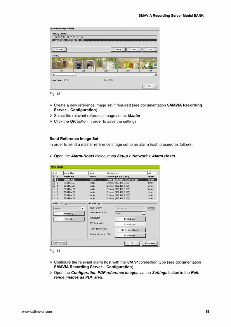
Send Reference Image SetIn order to send a master reference image set to an alarm host, proceed as follows:
¾ Open the Alarm-Hosts dialogue via Setup > Network > Alarm Hosts.
Fig. 14
¾ Configure the relevant alarm host with the SMTP connection type (see documentation SMAVIA Recording Server – Configuration).
¾ Open the Configuration PDF reference images via the Settings button in the Refe-rence images as PDF area.

www.dallmeier.com 19
SMAVIA Recording Server Modul BANK
Fig. 15
Manual Transmission ¾ Enable the Send reference images as PDF checkbox. ¾ Select in the Send reference images as PDF area the required countdown (immedi-ately, 1, 2, 5 or 10 minutes) from the dropdown menu.
¾ Click the Send button to start the process. ¾ Click the OK button in order to close the dialogue.
The reference image set is sent once after the countdown.
Continuous Broadcast ¾ Enable the Send reference images as PDF checkbox.
¾ Enable the Interval checkbox. ¾ Select the required Interval from the dropdown menu
or
¾ Enable the Point in time option. ¾ Select the required option: Daily at, Weekly on oder Monthly on. ¾ Set the required daily, weekly or monthly point in time.
¾ Click the OK button in order to close the dialogue.
The reference image set is sent continuously at the specified point in time of the day, week or month.

www.dallmeier.com 20
SMAVIA Recording Server Modul BANK
8 ExportThe evaluation of the recordings and the export of single images and image sequences is made with the corresponding management software SMAVIA Viewing Client. The client computer has to meet the following requirements:
Component Minimum Best Practice (recommendation)Operating system
Microsoft Windows 7 Professional (32 Bit)
Microsoft Windows 7/8 Professional (64 Bit)
CPU 2,66 GHz Dual-Core 3,6 GHz Quad-CoreRAM 2 GB DDR3 8 GB DDR3Recommended graphics board
NVidia GeForce GT 640 GDDR5 NVidia GeForce GTX 750
Network 100 Mbit/s 1000 Mbit/s
Note the corresponding data sheet and the documentations on SMAVIA Viewing Client for further information.
8.1 Single ImagesThe function Image Export allows to save single images locally or export them to an ex-ternal storage device.
¾ Activate the playback mode of the required camera. ¾ Select with the search functions the required image.
The function Image Export can be activated with the menu Action > Image > Export or with the control panel as described in the following.
¾ Click the Picture processing button.
The control panel for the image export is displayed.
Fig. 16
¾ Click the Export this picture button.
The Export/Print dialog is displayed.

www.dallmeier.com 21
SMAVIA Recording Server Modul BANK
Fig. 17
¾ Select the required option (see below). ¾ Click OK.
The Save as dialog in the Windows Explorer is displayed.
¾ Enter a name for the image. ¾ Select a storage medium and / or a directory if required. ¾ Click Save.
The Modified (WYSWG) option allows to print the image with all the individual image changes – as it is displayed on the screen. With the Original option the unaltered original image is printed – as it is stored in the track.
8.2 Image SequencesThe Backup function allows to backup image sequences of a track. Backups can also be saved to external storage media. Backups can be played in SMAVIA Viewing Client as local tracks.
¾ Activate the playback mode of the required camera.
The function Backup can be activated with the menu Action > Secured > Backup or with the control panel as described in the following.
¾ Click the Create backup button in order to open the backup control panel.
Fig. 18

www.dallmeier.com 22
SMAVIA Recording Server Modul BANK
Set Start And Stop Time Of The Backup
¾ Click the Start time button.
The Set start time dialog is displayed.
Fig. 19
Note: The Current button allows you to take over the Date and the Time of the currently displayed image.
¾ Enter the Date and the Time. ¾ Confirm with OK.
The start time is displayed in the Start field in the Backup info window.
¾ After defining the Start time click the Stop time button and proceed analogously to the start time.
Set Target Folder For The Backup
¾ Click the Define target folder button.
The Save as Windows dialog is displayed.
¾ Select with the Windows Explorer the required directory. ¾ Enter a name for the backup. ¾ Click Save.
Start Backup
¾ Click the Start backup button.
The current backup process is displayed in the Backup working dialog:

www.dallmeier.com 23
SMAVIA Recording Server Modul BANK
Fig. 20
The progress of the backup is displayed in the % bar.
Exit Backup Mode
After the backup is complete you can activate the playback mode (click on the Create backup button) or the live mode (click on the Live access button) of the current camera.