Recent progress in covalent organic framework thin films ...
37
Journal Name ARTICLE This journal is © The Royal Society of Chemistry 20xx J. Name ., 2013, 00, 1-3 | 1 Please do not adjust margins Please do not adjust margins Received 00th January 20xx, Accepted 00th January 20xx DOI: 10.1039/x0xx00000x www.rsc.org/ Recent progress in covalent organic framework thin films: fabrications, applications and perspectives Han Wang, † a Zhuotong Zeng, † b Piao Xu, † a Lianshan Li, † c Guangming Zeng,* a Rong Xiao,* b Zhiyong Tang,* c Danlian Huang, a Lin Tang, a Cui Lai, a Danni Jiang, a Yang Liu, a Huan Yi, a Lei Qin, a Shujing Ye, a Xiaoya Ren a and Wangwang Tang a As a newly emerging class of porous material, covalent organic frameworks (COFs) have attracted much attention due to their intriguing structural merits (e.g., total organic backbone, tunable porosity and predictable structure). However, the insoluble and unprocessable features of the bulk COF powders limit their applications. To overcome these limitations, considerable efforts have been devoted to exploring the fabrication of COF thin films with controllable architectures and opening the door for their novel applications. In this critical review, we aim to provide recent advances in the fabrications of COF thin films not only supported on substrates but also acted as free-standing nanosheets by both bottom-up and top- down strategies. The bottom-up strategy contains solvothermal synthesis, interfacial polymerization, room temperature vapor-assisted conversion, and synthesis under continuous flow conditions, while the top-down strategy contains solvent- assisted exfoliation, self-exfoliation, mechanical delamination, and chemical exfoliation. In addition, the applications of COF thin films including energy storage,semiconductor devices, membrane-separation, sensors, and drug delivery are summarized. Finally, to speed up further research, a personal perspective covering synthetic strategies, mechanisms and applications is presented. 1. Introduction For decades, porous materials have attracted sustained attention due to their abundant voids containing structure which enables them to host other functional molecules. 1-5 Owing to their unique features, porous organic materials, such as hypercrosslinked polymers (HCPs), 6, 7 conjugated microporous polymers (CMPs), 8-10 and porous aromatic frameworks (PAF), 11-13 have been widely studied. However, constructing persistent porous structure linked by covalent bonds is still a complicated problem in spite of that some remarkable progress have been made these years. 14-16 Crystalline networks with ordered pores are urgently in need. Covalent organic frameworks (COFs), as a class of newly emerging porous material, have attracted particular interests. Quite different from classical short-range covalent polymers connected via irreversible condensation, 17 COFs show highly ordered crystalline structures through reversible reactions. 18 Compared to the traditional crystalline porous solids such as zeolites 19, 20 and metal-organic frameworks (MOFs) 21-23 , COFs with precisely pre-designable structures and tailored functionalities are able to achieve structural and chemical control that are specific to functions. 24 Moreover, they possess the advantages of structural diversity, 25 low density, 26 high thermal stability, 27, 28 and permanent porosity. 29 In 2005, Yaghi and co-workers, for the first time, synthesized a type of pure two-dimensional (2D) organic frameworks, namely COF-1 and COF-5, which are composed of organic building subunits connected through strong covalent bonds by reticular chemistry. 30 Afterward, a great variety of COFs have sprung up including imine-linked COFs, 31-34 hydrazone-linked COFs, 35, 36 and keto-enol-linked COFs (Fig. 1). 37-39 Their abovementioned unique characters as well as common natures of organic polymers endow them great application potential in energy storage, 40-42 drug delivery, 43, 44 adsorption, 45, 46 separation, 47 catalysis, 48 optoelectronics, 49, 50 and sensing. 51 However, all of these applications are currently established on the basis of insoluble and unprocessable COF powders. Early in 2007, Kitagawa and Matsuda demonstrated that porous polymers are insoluble and difficult to be prepared into thin layers in spite of furnished nanosized channels or cavities. 52 The ultimate goal is to construct various nanodevices with controllable arrangements of porous modules’ channels. Indeed, the difficulties in membrane formation greatly hinder the practical applications of COFs. For example, an anthraquinone based COF powder was incorporated into carbon black to act as an electrode material leading to a higher capacitance compared with that of electrode without COF a. College of Environmental Science and Engineering, Hunan University and Key Laboratory of Environmental Biology and Pollution Control (Hunan University), Ministry of Education, Changsha 410082, P. R. China. E-mail: [email protected] b. Department of Dermatology, Second Xiangya Hospital, Central South University, Changsha 410011, P. R. China. E-mail: [email protected] c. CAS Key Laboratory of Nanosystem and Hierachical Fabrication, CAS center for Excellent in Nanoscience, National Center for Nanoscience and Technology, Beijing 100190, P.R. China. E-mail: [email protected] † These authors contribute equally to this article. Electronic Supplementary Information (ESI) available: [details of any supplementary information available should be included here]. See DOI: 10.1039/x0xx00000x Accepted MS
Transcript of Recent progress in covalent organic framework thin films ...
Journal Name
ARTICLE
This journal is © The Royal Society of Chemistry 20xx J. Name., 2013, 00, 1-3 | 1
Please do not adjust margins
Please do not adjust margins
Received 00th January 20xx,
Accepted 00th January 20xx
DOI: 10.1039/x0xx00000x
www.rsc.org/
Recent progress in covalent organic framework thin films: fabrications, applications and perspectives
Han Wang, †a Zhuotong Zeng, †b Piao Xu, †a Lianshan Li, †c Guangming Zeng,*a Rong Xiao,*b Zhiyong Tang,*c Danlian Huang,a Lin Tang,a Cui Lai,a Danni Jiang,a Yang Liu,a Huan Yi,a Lei Qin,a Shujing Ye,a Xiaoya Ren a and Wangwang Tang a
As a newly emerging class of porous material, covalent organic frameworks (COFs) have attracted much attention due to
their intriguing structural merits (e.g., total organic backbone, tunable porosity and predictable structure). However, the
insoluble and unprocessable features of the bulk COF powders limit their applications. To overcome these limitations,
considerable efforts have been devoted to exploring the fabrication of COF thin films with controllable architectures and
opening the door for their novel applications. In this critical review, we aim to provide recent advances in the fabrications
of COF thin films not only supported on substrates but also acted as free-standing nanosheets by both bottom-up and top-
down strategies. The bottom-up strategy contains solvothermal synthesis, interfacial polymerization, room temperature
vapor-assisted conversion, and synthesis under continuous flow conditions, while the top-down strategy contains solvent-
assisted exfoliation, self-exfoliation, mechanical delamination, and chemical exfoliation. In addition, the applications of COF
thin films including energy storage,semiconductor devices, membrane-separation, sensors, and drug delivery are
summarized. Finally, to speed up further research, a personal perspective covering synthetic strategies, mechanisms and
applications is presented.
1. Introduction
For decades, porous materials have attracted sustained
attention due to their abundant voids containing structure
which enables them to host other functional molecules.1-5
Owing to their unique features, porous organic materials, such
as hypercrosslinked polymers (HCPs),6, 7 conjugated
microporous polymers (CMPs),8-10 and porous aromatic
frameworks (PAF),11-13 have been widely studied. However,
constructing persistent porous structure linked by covalent
bonds is still a complicated problem in spite of that some
remarkable progress have been made these years.14-16
Crystalline networks with ordered pores are urgently in need.
Covalent organic frameworks (COFs), as a class of newly
emerging porous material, have attracted particular interests.
Quite different from classical short-range covalent polymers
connected via irreversible condensation,17 COFs show highly
ordered crystalline structures through reversible reactions.18
Compared to the traditional crystalline porous solids such as
zeolites19, 20 and metal-organic frameworks (MOFs)21-23, COFs
with precisely pre-designable structures and tailored
functionalities are able to achieve structural and chemical
control that are specific to functions.24 Moreover, they possess
the advantages of structural diversity,25 low density,26 high
thermal stability,27, 28 and permanent porosity.29
In 2005, Yaghi and co-workers, for the first time,
synthesized a type of pure two-dimensional (2D) organic
frameworks, namely COF-1 and COF-5, which are composed of
organic building subunits connected through strong covalent
bonds by reticular chemistry.30 Afterward, a great variety of
COFs have sprung up including imine-linked COFs,31-34
hydrazone-linked COFs,35, 36 and keto-enol-linked COFs (Fig.
1).37-39 Their abovementioned unique characters as well as
common natures of organic polymers endow them great
application potential in energy storage,40-42 drug delivery,43, 44
adsorption,45, 46 separation,47 catalysis,48 optoelectronics,49, 50
and sensing.51 However, all of these applications are currently
established on the basis of insoluble and unprocessable COF
powders. Early in 2007, Kitagawa and Matsuda demonstrated
that porous polymers are insoluble and difficult to be prepared
into thin layers in spite of furnished nanosized channels or
cavities.52 The ultimate goal is to construct various nanodevices
with controllable arrangements of porous modules’ channels.
Indeed, the difficulties in membrane formation greatly hinder
the practical applications of COFs. For example, an
anthraquinone based COF powder was incorporated into
carbon black to act as an electrode material leading to a higher
capacitance compared with that of electrode without COF
a. College of Environmental Science and Engineering, Hunan University and Key Laboratory of Environmental Biology and Pollution Control (Hunan University), Ministry of Education, Changsha 410082, P. R. China. E-mail: [email protected]
b. Department of Dermatology, Second Xiangya Hospital, Central South University, Changsha 410011, P. R. China. E-mail: [email protected]
c. CAS Key Laboratory of Nanosystem and Hierachical Fabrication, CAS center for Excellent in Nanoscience, National Center for Nanoscience and Technology, Beijing 100190, P.R. China. E-mail: [email protected]
† These authors contribute equally to this article. Electronic Supplementary Information (ESI) available: [details of any supplementary information available should be included here]. See DOI: 10.1039/x0xx00000x
Accepted MS

ARTICLE Journal Name
2 | J. Name., 2012, 00, 1-3 This journal is © The Royal Society of Chemistry 20xx
Please do not adjust margins
Please do not adjust margins
loading, whereas only 2.5 % of diaminoanthraquinone (DAAQ)
moieties were available in the system because of the random
oriented COF powders and non-optimal interface.38 Thus, new
strategies that can fabricate COFs into crystalline and ordered
thin films are highly required for their further practical
applications.
The bottom-up approach is the first important strategy
that enables COFs to be deposited on specific substrates or
polymerized at interface with controllable thickness and surface.
Dichtel and co-workers pioneered the research on COF films
growth on single-layer graphene (SLG) via a bottom-up method
under solvothermal conditions.53 The as-prepared COF films
exhibited improved crystallinity over bulk COF powders, which
are ideal for organic electronic devices. This intriguing research
has opened the door for COF thin films fabrication. Since then,
several innovative or modified methods for COF-film growth
related to bottom-up strategy have been employed and
oriented thin films supported by various substrates have been
obtained. By now, four major methods have been used for the
fabrication of COF thin films on different substrates or at
interfaces: (1) solvothermal synthesis, (2) interfacial
polymerization, (3) synthesis under continuous flow conditions,
and (4) room temperature vapor-assisted conversion. All of
these strategies will be discussed in detail in Section 2.
Another attractive method is top-down synthesis, which
bulk COF powders are directly exfoliated into free-standing COF
films, namely COF nanosheets (CONs). As we know,
dimensionality is one of the most important parameters that
affects the materials properties.54, 55 Bulk lamellar COFs are
stacked by atomic thick layers via weak van der Waals force.
Inspired by the excellent properties of graphene which is
exfoliated from its parent graphite,56-58 Félix Zamora group first
exfoliated COF-8 into CONs with the thickness down to 4~8
nm.59 The dimension related properties enable the thin layered
COF-8 nanosheets to be incorporated into devices or act as
nanosensors. After that, various functional CONs have been
delaminated from their bulk counterparts by various methods
such as solvent-assisted exfoliation, mechanical delamination,
and self-exfoliation. All these different ways will be discussed
comprehensively in the following.
Though there are many critical reviews focused on
reticular chemistry of COF powders,60-65 the review related to
COF thin films is rare. In this review article, we focus on the
recent developments on the fabrication of COF thin films
supported not only on the substrate but also as free-standing
forms. First, we summarized the synthesis strategies related to
bottom-up and top-down method. Second, we discussed the
existing applications of thin films in different fields such as
energy storage, semiconductor devices, membrane-separation
and sensors. Finally, we demonstrated a personal perspective
regarding to the future development. It is worth mentioning
that since the development of single-layered COF has been
recently reviewed,66 we focus on few layered COF thin films and
exfoliated CONs in this article by collecting recent important
developments in this exciting field and presenting critical issues,
challenges, and perspectives.
The following Fig. 2 and 3 will be used to guide the readers
to better understand the monomers and reversible reactions
utilized for the construction of COF thin films.
2. Bottom-up strategy for the fabrication of COF thin films
As stated above, the excellent properties and imperious
demands of COF thin films have triggered substantial research
interests for their synthesis. Bottom-up strategy, which is
usually related to the functional coatings on selected surface,
has been widely used in COF thin film fabrications. The key of
this strategy is to control the growth orientation of the film and
avoid random extension. Up to now, a number of highly
oriented COF thin films have been synthesized on various
substrates or interfaces by bottom-up strategy. However,
finding appropriate synthetic conditions for the COF thin films
growth is not easy. Generally, solvothermal synthesis is the
most frequently utilized method for flat COF thin films
production. And other brilliant methods have also been
employed containing interfacial synthesis, room temperature
vapor-assisted conversion, and synthesis under continuous flow
conditions. In this section, we will summarize these approaches
based on existing studies.
2.1 Solvothermal synthesis
As a simplest method, solvothermal synthesis is to coat COF
powders on arbitrary support by immersing proper substrates
into a COF reaction mixture, followed by washing with related
organic solvents and drying under a stream of N2. The first
successful production of continuous COF thin films was
achieved on the basis of the traditional COF synthesis route by
using solvothermal method, which put no specific requirements
on the surface of the supporting substrates. For instance, in the
case of COF-5,30 the traditional synthesis route is as follow: the
polymerization of 2, 3, 6, 7, 10, 11-hexahydroxytriphenylene
(HTTP, 1) and 1, 4-phenylenebis(boronic acid) (PBBA, 5) was
conducted in a Pyrex tube with mesitylene and dioxane as
solvents. The reaction mixture was heated to 100 ºC for 72 h to
yield a free-flowing gray-purple powder. To deposit the COF
powders on the substrate for thin film formation, the most
native way might be to directly submerge the substrate into the
bulk COF reaction liquid.
SLG with remarkable photoelectric properties, especially
the 2D atomically precise structure, is a suitable interface for
coating 2D layered materials and can be transferred to other
different substrates.67 Dichtel and co-workers demonstrated
that oriented COF thin films can be formed on SLG supported by
different substrates, such as SLG/Cu, SLG/SiC, SLG/SiO2, under
straightforward solvothermal conditions.53 Specifically, the
COF-5 thin films was formed under the solvothermal
condensation of HHTP (1) and PBBA (5) at 90 ºC in the solution
of mesitylene and dioxane with the presence of SLG/Cu
substrate (Fig. 4a-c). The hexagonal lattice of the COF-5 grains
aligned parallel to the substrate surface, which was verified by
powder x-ray diffraction (PXRD) and grazing incidence
diffraction (GID). This simple synthetic method is general for
Accepted MS

Journal Name ARTICLE
This journal is © The Royal Society of Chemistry 20xx J. Name., 2013, 00, 1-3 | 3
Please do not adjust margins
Please do not adjust margins
SLG transferring to other substrates including transparent fused
SiO2 (SLG/SiO2). Importantly, the supporting substrates exert a
great impact on the qualities of the thin films containing the
uniformity and thickness. In the same reaction time, thicker
films were obtained on SLG/Cu compared with that of SLG/SiO2.
Subsequently, they further fabricated the HHTP-DPB COF thin
films with a thickness of 132 ± 18 nm and a series of Zn
phthalocyanine (ZnPc, 4) COF thin films with an average
thickness of 370 ± 30 nm on the transparent SLG/SiO2
substrate.68, 69
Soon after, Bein et al. fabricated a novel thiophene-based
BDT-COF thin film containing an electron donor unit.70 Different
from Dichtel’s work,53, 68, 69 a lower concentration of starting
monomers with Indium-doped tin oxide (ITO)-coated or
NIO/ITO-coated glass substrates was employed. As a result, a
smooth and continuous organic thin film with the thickness of
150-nm on ITO-coated glass substrate was observed from the
top-view and cross-sectional scanning electron microscopy
(SEM) images (Fig. 4d and e). X-ray diffraction (XRD)
measurement was employed to analyze the crystallinity of the
thin films. The absence of peaks at low 2θ (<20°) is related to
the mesoporous structure, while the strong and sharp
diffraction peak at 26.1° is referred to the π-π stacking of COF
layers. And GID investigation was further utilized to reveal the
preferred orientation of COF thin films that COF layers with
preferential orientation to the surface of ITO-coated glass were
synthesized verified by the reflection concentrated near q(z) =
0. The authors also grew BDT-COF thin films with high quality on
other polycrystalline inorganic substrates including NiO/ITO-
coated glass and Au substrate, which led to a conclusion that, in
contrast to the previous thinking, the π-π interaction is not the
necessary reason for the oriented film growth. Later, Liu and co-
workers prepared another electron donor contained TTF-COF
by using the conventional solvothermal method.71 In-suit
oriented growth of TTF-COF thin films on Si/SiO2 substrate and
transparent ITO-coated glass were also obtained.
While boronic ester COFs and some Schiff base COFs show
poor oxidative and hydrolytic stabilities, β-ketoenamine-linked
COFs are another class of COFs which exhibit excellent chemical
stability to water and aqueous acid. In 2015, Dichtel et al.
developed the β-ketoenamine-linked anthraquinone-based
COF (DAAQ-TFP COF) thin films by the modified solvothermal
synthesis.72 Considering that the quick reaction rate leads to the
out-of-order thin film, the triformylphluroglucinol (TFP, 17) was
added slowly into the mixture of 2, 6-diaminoanthraquinone
(DAAQ, 25) and Au substrate instead of directly putting the
substrate in the reaction liquid. The absence of N-H stretch
along with the presence of C-N stretch at 1250 cm-1 and C=C
stretch at 1560 cm-1 in Fourier transform infrared spectroscopy
(FT-IR) characterization verified the production of β-
ketoenamine linkage. The vertically oriented, layered structure
was further confirmed by GIDX with the observation of the (001)
peaks at Q⊥ = 1.8 Å -1 and Q‖ = 0. As demonstrated by the
authors, the thickness upper limit of this DAAQ-TFP COF thin
film was 300-400 nm in practice, which is related to the initial
concentration of the reactive monomers. Then, another β-
ketoenamine COF (DAB-TFP COF) thin films were successfully
prepared on various metals and oxides through solvothermal
strategy.73 In a previous report,74 DAB-TFP COF was fabricated
by condensing p-phenylenediamine (DAB, 22) with TFP (17) in a
sealed glass. As this classical reaction condition was not suitable
for the homogenous COF thin film growth, Lu et al. modified the
synthesis method by growing COF thin films on ITO substrate in
an autoclave. From the top-view and cross-sectional SEM
images, the as-prepared DAB-TFP COF thin film was smooth and
homogeneous with a thickness of approximately 200 nm (Fig. 4f
and g). XRD and GID measurements confirmed the crystallinity
of the thin films. XRD pattern of the obtained thin films revealed
no reflection at low 2θ degrees while a strong reflection at 27°
with respect to the π-π stacking of DAB-TFP COF layers emerged.
In the GID image, in-plane and out-of-plane diffraction of thin
films were observed clearly conformed to the bulk DAB-TFP COF.
In addition to the ITO substrate, the DAB-TFP COF thin films
were able to grow on other substrates, such as silicon, fluorine
doped tin oxide (FTO) and platinum.
In classical imine-linked COF fabrication, aldehyde and
amine moieties would produce amorphous polyimine
sediments during the solvothermal synthesis with the presence
of aqueous acetic acid catalyst, which hinders the nucleation
and growth of COF. Very recently, Yaghi and co-workers
introduced a new homogenous synthetic route to fabricate
imine-linked COF.75 In this newly developed route, tert-
butyloxycarbonyl (Boc) group was employed to protect amine
to avoid amorphous polyimine formation. More importantly,
this method is also helpful for oriented growth of imine-linked
COF thin film. As an example, LZU-1 COF thin films were
obtained via immersing the substrate into the reaction system
which contained 4-(tert-butoxycarbonylamino)-aniline (NBDPA,
30) to protect the amine moieties. With the homogenously
formation of protonated COF crystals, the nucleation of COFs
would be favored of the nucleation barrier facilitating the
growth of COF thin films. The as-prepared COF thin films were
highly oriented and uniform with the thickness of 190-nm which
can be tailored by varying the concentration of the growth
liquor and reaction time.
2.2 Interfacial synthesis
Interfacial synthesis is a widely used approach for polymer thin
films fabrications such as polyamides nanofilms and graphdiyne
nanosheets.76-78 In this approach, the interface is where the
reaction between monomers occurs. Thus, the COF growth is
limited to the confined interface region, leading to the
formation of thin films. Two kinds of interfaces have been used
in COF thin films synthesis, i.e., liquid/air interface and
liquid/liquid interface.
Recently, Bao and co-workers developed a new synthetic
method to grow COF thin films at the solution/air interface
given that the interface such as liquid/air interface is beneficial
to the growth of COF thin films due to the good control of COF
nucleation as well as the thickness.79 Trisamine 2,6-
dicarbaldehyde-4,8-dioctyloxybenzo[1,2-b:3,4-b’]dithiophene
(BDTA, 18) and bisaldehyde tris(4-aminophenyl)amine (TAPA,
27) were selected as the building blocks to form polyTB COF. For
the formation of polyTB thin films, a highly reflective thin film
Accepted MS
ARTICLE Journal Name
4 | J. Name., 2012, 00, 1-3 This journal is © The Royal Society of Chemistry 20xx
Please do not adjust margins
Please do not adjust margins
was first obtained by two days reaction of BDTA and TAPA in a
covered petri dish at the solution/air interface. However, the
prepared COF thin films were too rough to be incorporated into
devices. To get COF films with smooth surface, the authors
improved the method by using diluted mother solution filtered
from bulk polyTB synthesis as the film growing solution at the
solution/air interface. The thickness control could be achieved
by varying the incubation times. In this work, the thinnest and
thickest films were 1.8 nm and 29 nm, respectively, and both
had a roughness of 0.2 nm on average. More recently, Zhang
and co-workers prepared a monolayer imine-linked COF at the
water/air interface by using dynamic imine chemistry.80
Terephthalaldehyde (13) and 1, 3, 5-trihexyl-2, 4, 6-tris(4-
aminophenyl)benzene (33) were selected as monomers. Three
hydrophobic n-hexyl groups of the monomer 33 would set
upright on the surface and extend to the air, while the phenyl
rings might be fixed by the hydrophilic amino groups at the
water/air interface, which made monomer 33 ideal for the
interfacial reaction. Moreover, reversible imine linkage would
induce self-correction and therefore lead to few defects. In this
typical experiment, a dilute mixture of monomers in chloroform
was spread on the water/air interface and run overnight. A
smooth, free-standing monolayer sheet was then obtained with
a thickness of 0.7 nm under the well-designed control.
For the liquid/liquid interfacial polymerization, two non-
miscible liquids are utilized to create the interface at the
junction. For example, Dey et al. successfully synthesized a
series of large-scale thin films at the interface of
water/dichloromethane.81 To take an example, Tp (17) was
dissolved in dichloromethane, and 2, 2’-bipyridine-5, 5’-diamine
(Bpy, 42)-p-toluene sulfonic acid (PTSA) salt was added into
water on the top layer. The reaction took 72 h at room
temperature to obtain free-standing Tp-Bpy thin films with
highly crystalline nature. The thickness of the thin films is well-
adjusted by the selection of the precursor concentrations. And
the thin films could be easily transferred to arbitrary substrates,
such as metallic wires, holey grids and glass surfaces, and in the
meantime, remained the integrity of the crystalline structure
and physical shape. In another report, an imine-linked TAPB-
PDA COF thin film was presented at the liquid/liquid interface
by the polymerization of terephthalaldehyde (PDA, 13) and 1, 3,
5-tris(4-aminophenyl)benzene (TAPB, 26).82 Different from
traditional interfacial reaction, Sc(OTf)3 was employed to
facilitate the imine formation and limit the polymerization at
the interface. The Lewis acid catalyst Sc(OTf)3 with water
tolerance shows better solubility in the water phase compared
with that in the organic phase. As a result, Sc(OTf)3 catalyst are
preferentially dissolvable in the water phase while COF
monomers with preferred organic solubility were transferred to
the organic phase. This spatial segregation of COF monomers
and catalyst enabled the site-selective polymerization to
provide a thin film at the organic/water interface. Specifically,
water was added to the mixture solution of PDA, TAPB and 1, 4-
dioxane/mesitylene which contained small amounts of Sc(OTf)3
(Fig. 5a). The lateral dimension of the as-prepared thin films was
greatly depended on the size of the reaction vessel. And the
thickness of COF thin films could be easily adjusted by varying
the original monomer concentration and/or the volume of the
organic phase. Importantly, the thin films were readily
transferable to various substrates and the integrity retained,
even if it was the thinnest film.
2.3 Room temperature vapor-assisted conversion
Considering the instability of fragile building blocks which are
sensitive to the harsh conditions used in solvothermal synthesis,
Bein and co-workers came up with a mild method named room
temperature vapor-assisted conversion synthesis.83
Benzodithiophene-based BDT-COF and COF-5 were employed
to verify this strategy. Taking BDT-COF as an example, a mixture
of benzodithiophene diboronic acid (BDTBA, 8), HHTP (1), dry
acetone and absolute EtOH was first filtered through a syringe
filter after ultrasonication. Then, the obtained BDTBA/HHTP
mixture was drop-casting on a glass substrate, followed by
putting the substrate into a desiccator together with a small
glass vessel loaded with mesitylene and dioxane. A dark-green
organic layer with the thickness of 7.5 μm can be obtained after
72 h at room temperature. It should be noted here that the
thickness control can be achieved by tailoring the droplet
volume as well as the concentration. Specifically, when
decreasing the droplet volume to 2/5 of former used volume
and keeping other conditions the same, the thickness of the COF
thin films can be reduced to 2 μm. On this basis, changing the
concentration of the droplet to 1/3 of the previous
concentration, a homogeneous BDT-COF films with the
thickness of 300 nm was obtained. This excellent method allows
constructing COF thin films with fragile precursors as well as on
sensitive substrates, and therefore leads to wider applications.
2.4 Synthesis under continuous flow conditions
In contrast to the conventional static growth procedure, Dichtel
et al. synthesized a smooth and dense COF thin film under
continuous flow conditions recently.84 Considering the poor
control over the polymerization in previous method, they
modified the 2D COF thin films growth using a flow cell, which
enabled the COF formation amenable. In order to synthesize
COF-5 in a flow cell, the monomers HHTP (1) and PBBA (5) first
reacted slowly at 25 ºC, and then COF-5 formed after 2 min of
induction period when the temperature rose to 90 ºC.
Specifically, the reaction mixture was pumped through a
reservoir with a heated temperature of 90 ºC, and then entered
into a flow cell equipped with a quartz crystal microbalance
(QCM) substrate for mass deposition monitor. The authors
investigated the relation between the reaction conditions
(temperature, resident time, reaction mixture composition, and
the flow rate) and thin film formation. For example, the resident
time changes the average polymerization degree of reaction
mixture when it reaches the substrate. Specifically, short
resident time results in monomers and small oligomers
encountering the QCM substrate, while longer resident time
makes for larger species reaching the growth substrate.
Meanwhile, a series of boronate ester-linked COFs, DPB-COF,
TP-COF, and COF-10 were grown in flow to confirm the
suitability of the method. As a result, for the first time, constant
deposition rate can be achieved and film thickness can be
controlled under continuous flow conditions.
Accepted MS

Journal Name ARTICLE
This journal is © The Royal Society of Chemistry 20xx J. Name., 2013, 00, 1-3 | 5
Please do not adjust margins
Please do not adjust margins
The COF thin films fabricated via bottom-up strategy are
summarized in Table 1. As mentioned previously, while there
are several methods with respect to bottom-up strategy, the
simple and straightforward solvothermal synthesis is the most
frequently used method. However, limitations still exist: (1)
unreacted monomers and small oligomers may contaminate
the thin films and block the pores; and (2) it is difficult to
monitor the nucleation during the film formation. Synthesis
under continuous flow conditions solves the problem of thin
film contamination, however, in the cost of monomer waste.
The approach related to the reuse of unreacted monomers
needs to be explored. In that case, room temperature vapor-
assisted conversion synthesis and interfacial synthesis seem to
be more attractive, but their applicability requires the further
research. In short, more comprehensive studies about optimal
reaction conditions such as temperature, concentration and
reaction times of COF thin film growth are clearly warranted,
and the influence of the chosen substrate should be discussed
deeper. Moreover, additional methods are still needed.
3. Top-down strategy for the fabrication of COF thin films
Different from the abovementioned bottom-up strategy, the top-
down method means simple preparation of free-standing single-
/few-layered COF thin films from bulk materials, instead of growing
it on specified substrates or interface. Compared to the bottom-up
method that is usually expensive and needs strict conditions, the top-
down method is cheaper and more straightforward. As we know that
bulk 2D COF crystals are layered structures with different layers
stacked each layer along the vertical direction via weak interactions
including van der Waals force and/or hydrogen bonding. The top-
down synthesis is designed to break the π-π interactions between
the COF layers by internal or external force to produce single or few-
layered free-standing COF thin films. In this section, we will
demonstrate various synthetic methods in regard to top-down
strategy including solvent-assisted exfoliation, mechanical
delamination, chemical exfoliation and self-exfoliation. The
distinction between these different ways comes from the source of
the peel strength. For example, the self-exfoliation method mainly
relies on the internal force while the solvent-assisted exfoliation and
mechanical delamination are caused by external force. In the
following, all the different methods will be elaborated separately.
3.1 Solvent-assisted exfoliation
As the most commonly used method for COF exfoliation, a
plenty of examples could be found in the published works.59, 85-
88 This review selects several representative cases to elucidate
this simple but effective method. Inspired by the successful
exfoliation of graphene by sonication in well-chosen solvents,89
Berlanga et al., for the first time, obtained the delaminated
CONs with 10-25 layers by using solvent-assisted exfoliation
method.59 Boronic ester-linked COF-8 was selected as the bulk
sample, which was synthesized by the condensation of HHTP (1)
and BTPB (9) demonstrated in previous literature.90 The authors
expected to weaken the π-π interactions between COF layers
via mechanical force like sonication with the help of suitable
solvent. This is possible given that sonication can accelerate the
intercalation of solvent molecules into the COF, which increases
the interlayer space and therefore weakens its interlayer
interaction. Moreover, solvent plays an important role in the
exfoliation of the layered COFs, which not only exfoliates the
layered COFs but also stabilizes the as-formed nanosheets.
Specifically, suitable surface tension between the layer crystal
and solvent is a key point in lowering the energy and improving
the efficiency of exfoliation. Particular solvent with COF-
matched surface energy enables the balance of the exfoliated
energy.89, 91 Low exfoliation rates are found when an improper
solvent is used. Furthermore, proper solvent can also prohibit
the aggregation of the nanosheets.92 Among the solvents
utilized, CH2Cl2 stood out because of its excellent properties
such as suitable surface energy, volatility and high chemical
purity. A certain amount of COF-8 powders was dissolved in
anhydrous CH2Cl2 and the mix liquor was sonicated for 15 min.
The consequent suspension was then centrifuged for 5 min
leading to a color-less solution. Finally, the solid residue of the
solution was characterized by infrared radiation (IR), X-ray
photoelectron spectroscopy (XPS), and so on. Specifically, the IR
signature of the delaminated CONs was same as that of COF-8
bulk powders. As revealed by the XPS data, the exfoliated CONs
showed different graphic feature which indicates a disruption
of the interlayer interactions and the obtainment of randomly
oriented sheets. The as-prepared sheet-like structure was
further confirmed by AFM and TEM. It is worth mentioning that
the obtained CONs could be transformed to any substrates
without affecting the original properties. To better understand
the influence factors with respect to the COF exfoliation, a
further research on the effects of COF structure on the
exfoliation was introduced.85 A series of
poly(aryleneethynylene) COFs with different pore size (from 1.4
to 3.3 nm) was employed to study the impacts of porosity and
reaction time. This kind of COFs was constructed by carbon-
carbon bonds via Sonogashira-Hagihara coupling procedures.93
The results showed that smaller pore size and longer sonication
time lead to thinner CONs which means higher degrees of
exfoliation. Importantly, the impact of porosity can be
weakened by the increase of sonication time.
However, the application of the as-synthesized boronate
ester COF thin films is limited due to its poor hydrolytic and
oxidative stability as well as the palpable interlayer stacking
energies. As the acyl hydrazones could overcome the above
drawbacks, Dichtel and co-workers prepared the 2D hydrazone-
linked COF-43 thin films under mild conditions and further
proved the feasibility of the solvent-assisted exfoliation method
(Fig. 6a).86 COF-43 was fabricated by the method reported
previously and confirmed by PXRD.36 Interestingly, the
crystallinity of COF-43 became weak when the powder was
submerged into the dioxane, H2O, and DMF which was different
from that of other common solvents such as THF, CHCl3 and
MeOH. In order to prove that the weakness of crystalline was
resulted from the exfoliation of the multilayers rather than the
disruption of covalent bond, the authors first eliminated the
hydrolysis process proved by FT-IR and solid-state IR which
demonstrated the integrity of hydrazine links. Then, AFM and
Accepted MS

ARTICLE Journal Name
6 | J. Name., 2012, 00, 1-3 This journal is © The Royal Society of Chemistry 20xx
Please do not adjust margins
Please do not adjust margins
selected area electron diffraction (SAED) data of the contrast
experiment further verified the exfoliation of layered COF-43
and the function of solvent in the case of COF-43 exfoliation that
exfoliating solvents led to thinner COF-43 nonasheets while
non-exfoliating solvents obtained poor-constructed COF-43
multilayers. Very recently, another imine-linked TPA-COF thin
films were prepared by Zhang and co-workers via simply
sonicating TPA-COF-ethanol mixture.87 TPA-COF powders were
dispersed in ethanol and the mixture was then sonicated for 3
h. After 24 h stewing, the upper colloidal suspension containing
exfoliated TPA-COF nanosheets was collected and centrifuged.
The free-standing TPA-COF thin films were left as sediments.
TEM characterization confirmed the 2D nanosheets structure
and AFM image showed that the thickness of as-synthesize TPA-
COF thin film was 3.5 ± 0.3 nm equivalently to 9 ± 1 layers (Fig.
7a and b). Interestingly, this ultrathin quality enabled the
visualization of detailed structure information of TPA-COF
nanosheets such as pore channels and building units via low-
dose imaging technique of TEM for the first time (Fig. 7c and d).
3.2 Mechanical delamination
Another effective and precaution-free method, namely
mechanical delamination, was employed by Banerjee et al.94
When fabricating TpPa-1 and TpPa-2 by using a solvent-free
room-temperature mechanochemical method, it was
discovered that the exfoliated COF layers also existed.95 As
demonstrated by the authors, mechanical grinding would break
the strong π-π interactions between COF layers which made the
COF exfoliation possible. With this in mind, they further
prepared a series of TpPa and TpBD COF thin layers under the
same condition (Fig. 5b). A certain amount of bulk COF materials
was put in a mortar with several drops of methanol and then
fully grinded by a pestle at room temperature for 30 min. Then,
the collected powder was dispersed in the methanol solution
and centrifuged until a clear liquid was obtained. The free-
standing COF thin films were obtained after completely
evaporating the solvents. The TEM image and AFM
measurement confirmed the existence of flat nanosheet-like
structures with the thickness of 3-10 nm corresponding to ~10-
30 COF layers (Fig. 7e and f). Meanwhile, the FT-IR and Raman
spectroscopies indicated the structure integrity of COF thin
films after delamination except for the decrease of crystallinity
which was verified by the PXRD profile. Moreover, these COF
thin films remained stable in both acidic and basic solutions
similar to their parent COFs.
Different from the mortar & pestle system, another
scalable and simple mechanical delamination method with
respect to ball milling was employed to delaminate an
anthraquinone based COF (DAAQ-TFP-COF).96 The vibratory ball
worked at room temperature with the DAAQ-TFP-COF materials
put in a milling pot without any other exfoliating agents to
obtain DAAQ-TFP-COF nanosheets. Thickness was tailored by
changing the vibration frequency and time. By elegantly
selecting the vibration frequency of 50 Hz for 0.5 h, a free-
standing DAAQ-TFP-COF thin film with a thickness of 3-5 nm was
obtained. Later on, Hu and co-workers also fabricated the
melamine/o-phthalaldehyde condensed CONs using modified
ball milling method.97 The COF was prepared via solvothermal
procedure.98 Then the as-prepared COF was wet-ball milled in
the presence of DMF at 225 rpm for 24 h and sonicated 30 min
for dispersion. The obtained mixture was centrifuged to collect
supernatant which was regarded as CONs. Comparing the XRD
patterns of bulk COF and the given CONs, the intensity of the
characteristic diffraction peak at around 23.5° dropped
remarkably related to CONs indicating the production of CONs
considering the crystalline damage caused by the external ball
milling force. On the other hand, the COF and CONs shared
similar chemical structure despite the slight change as
evidenced by the FT-IR spectrum. TEM image verified the
multihole nanosheets. XPS spectra was employed to investigate
the bond state and atom composition of the samples. The
characteristic peaks of C1s in high-resolution XPS spectra were
assigned to C−C (284.7 eV), C−N (285.4 eV), C=N (287.4 eV), and
C=O (280.0 eV). Two typical peaks were revealed in N1s high-
resolution XPS spectra, comprising N=C (389.5 eV) and N−H
(399.9 eV). And the atomic percentage of carbon, nitrogen, and
oxygen was 64.86%, 27.57%, and 7.62%, respectively. As a
result, the CONs were successfully exfoliated from COF
counterparts by ball milling.
3.3 Chemical exfoliation
Considering the poor dispersion stability and the difficult
thickness control of exfoliated CONs,35, 99, 100 Khayum et al.
synthesized the N-hexylmaleimide-functionalized CONs
chemically exfoliated from an anthracene-based COF by [4 + 2]
cyaloaddition reaction (Fig. 8a and b).101 And a centimeter-scale
self-standing COF thin film was further obtained at water/air
interface via layer by layer assembly. As known, 9- and 10-
position of anthracene units are easy to be attacked via [4 + 2]
cyaloaddition reaction.102 The π-π stacking between layers and
the planarity of each layer can be weakened with the
intercalation of N-hexylmaleimide into the COF backbone which
leads to the COF exfoliation. In this exfoliation process, the
anthracene-based imine-linked COF DaTp was first condensed
by 2, 6-diaminoanthracene (Da, 24) and Tp (17) through
standard solvothermal protocol. Then [4 + 2] cycloaddition
reaction was employed to introduce N-hexylmaleimide into
DaTp, which led to the weaker π-π interactions between COF
layers, and thereby obtained the exfoliated DaTp COF
nanosheets. Considering that the long alkyl chains and dipole
forces can make it possible for DaTp COF nanosheets to form
thicker thin films by layer by layer assembly, a conventional
air/water interfacial layer by layer assembly method was
employed to control the thickness.103 A suspension of DaTp COF
nanosheets in dichloromethane (DCM) was added drop wise
into a beaker of water, where water served as the liquid phase
considering the fact that the hydrophobic alkyl chains enable
the levitation of the nanosheets on the surface of water, while
DCM with lower surface energy and higher vapor pressure was
act as the spreading solvent. A temporary DCM-water bilayer
was generated by quickly spreading the nanosheets suspension
to the water surface, and a semi-transparent COF thin film was
obtained after rapidly evaporating the DCM layer within 60
seconds. SEM, AFM and optical microscopy images further
Accepted MS
Journal Name ARTICLE
This journal is © The Royal Society of Chemistry 20xx J. Name., 2013, 00, 1-3 | 7
Please do not adjust margins
Please do not adjust margins
indicated the formation of a continuous, defect-free, and free-
standing COF thin film with a thickness of 5-6 nm (Fig. 8c-f). To
verify the thickness control of layer by layer assembly, three
parallel experiments with different suspensions were also
conducted, which indicated that higher concentration led to
thicker films.
Later, the same group further expanded the research to
synthesize CONs via post-synthetic modifications.5 Hydroxyl (-
OH) units are perfect moiety for modification because of their
facile derivatizable nature under moderate conditions.104
Keeping this in mind, the authors elaborately chose 4-
aminosalicylhydrazide (ASH, 36) as one of the linkers for COF
construction while 4-aminobenzohydrazide (APH, 34) without
hydroxyl was chosen for comparison. 1, 3, 5-
triformylphloroglucinol (Tp, 17) and diamines (APH, 34, or ASH,
36) were condensed with the existence of PTSA through a
neoteric solid-state mixing procedure to synthesize TpAPH and
TpASH. And a three-step approach was employed to obtain
functional target CONs. First, with the adding of glycidol (Glc),
the phenolic hydroxyl groups were converted to alkyl hydroxyl
groups to make TpASH-Glc CONs by opening the epoxy ring.
Then the as-synthesized surface alkyl hydroxyl groups were
transformed to amines in the presence of APTES for amine
functionalized CONs producing. Finally, the cellular targeting
ligand folic acid (FA) was involved to fabricate objective CONs
(TpASH-FA). As demonstrated by the authors, the as-prepared
CONs owned excellent aqueous dispersibility due to their
surface functionalization.
3.4 Self-exfoliation method
In contrast to developing CONs with the aid of the external force,
the self-exfoliation method is more likely to depend on the well-
designed building block to induce the peeling-off by internal
force. For example, in El-Kaderi et al.’s work,105 the π-π
interactions between the as-prepared COF layers were reduced
due to the insert of triptycene units. Based on this, two methyl
groups were introduced into the 9, 10-position of triptycene
tricatechol (TPTC, 2) to further enlarge the distance between
the COF layers, which enabled the exfoliation of monolayer COF
thin film.106 More recently, Rahul Banerjee and co-workers
incorporated guanidinium units into the COF backbone to
obtain self-exfoliated ionic covalent organic thin films.107 The
authors fabricated three different CONs (TpTGCl (Fig. 9a−b),
TpTGBr, and TpTGI) through Schiff-based condensation using the
conventional solvothermal synthesis. From the PXRD pattern,
the crystallinity of the obtained CONs was relatively low. Weak
π-π stacking between the layers could be verified by the broad
peak at 2θ = ~27.3°. On the other hand, with the molecular
dynamics (MD) simulation studies, the average interlayer π-π
stacking distance of TpTGCl was increased from initial 3.338 Å to
~5.5-6 Å. The authors ascribed this to the inherent positive
charge of guanidinium units and the existence of the loosely
bound chloride ions, and concluded that the ionic CONs with 3-
6 layers were successfully synthesized, which was further
proved by TEM analysis as well as AFM measurements (Fig.
9c−h).106, 108 Compared to other breaking-off methods, self-
exfoliation method seems to be a simpler way because of its
internal synthesis and avoided restacking. Moreover, it’s
possible to use ionic building units not only to start up the self-
exfoliated process but also act as targeted functional group,
which broadens the applications of COF thin films.
The free-standing COF thin films fabricated via top-down
strategy are summarized in Table 2. Four major fabrication
methods related to top-down strategies have been explored.
Obviously, solvent-assisted exfoliation is the most frequently
used method. Compared with other methods, this method
enables the high-yield and massive production of ultrathin
nanosheets in solution at low cost, since the process is quite
simple. Chemical exfoliation and self-exfoliated process are able
to introduce functional groups not only avoiding aggregation
but also acting as targeted function. As for solvent-free
mechanical delamination, toxic organic solvents are well
avoided. While the aforementioned methods have their
respective advantages and have succeeded in the preparation
of free-standing COF thin films, there still have some shortages.
On the one hand, the obtainment of true single-layered
nanosheet is difficult and the aggregation of monolayers exists
because of the stacking interaction; on the other hand, the yield
of CONs is relatively low, which hinders the industrial
applications. What’s more, the generality of the methods has to
be proven. What is worth mentioning is that colloidal
suspensions of COFs provide new opportunities for free-
standing COF thin films.109, 110 Solution-casting of COF colloids
enables to obtain free-standing films with controlled size and
thickness. For example, Dichtel et al. reported a COF-5 film
formed by evaporating solvent from a colloidal suspension.109
The as-prepared film retains the integrity of crystallinity same
to the original colloidal solution and exhibits a preferential
orientation compared with that of thin films obtained from in-
suit growth on the substrates. These results represent an
important aspect for the developing free-standing COF thin film
using top-down strategy and further studies are also needed to
decode the film aggregation mechanism.
4. Applications of COF thin films
The application of bulk COFs suffers a lot from their insoluble
and unprocessable characters. It is necessary to facile
synthesize long-range ordered COF thin films for better
performance. As demonstrated above, various synthetic
methods have been employed in the COF thin films fabrication.
One can understand that different synthetic methods lead to
different properties of materials and therefore the different
applications. In this section, we will discuss the existing works
that COF thin films have been employed to achieve specialized
functions and summarize the applications covering energy
storage, separation membranes, chemical sensors, etc.
4.1 Energy storage
With the population growth and industrial explosion, one of the
most serious problems facing the world is energy shortage.
Clean, renewable energy sources and energy storage devices
including lithium ion battery, supercapacitors, and solar cells
are urgently needed.111-113 COF thin films with enhanced
Accepted MS
ARTICLE Journal Name
8 | J. Name., 2012, 00, 1-3 This journal is © The Royal Society of Chemistry 20xx
Please do not adjust margins
Please do not adjust margins
specific area, ultrathin thickness and accessible functional sites
are considered as promising platform for energy storage
applications. Some intriguing progress have been made in
energy storage based on COF thin films in recent years.
4.1.1 Lithium-ion batteries. Theoretically, ultrathin COF
thin films with limited layers enable the reduction of
ion/electron migration length as well as the facilitation of
ion/electronic diffusion. Moreover, a mass of available Li sites
on or near the surface also endow the rapid charge-discharge
cycles and the full utilization of redox sites. Anthraquinone as a
redox-active unit has attracted considerable attention in the
application of energy storage.114-116 Wang et al. conducted a
research on the usage of free-standing anthraquinone-based
COF thin films in Li+ batteries. Compared with bulk COF powders,
the exfoliated COF thin films owned the enhanced efficiency of
redox-active sites utilization and the rapid kinetics for lithium
storage due to their shorter Li+ diffusion pathways. In a typical
experiment, a redox-active DAAQ-ECOF with the thickness of 5
nm was prepared via mechanical milling method. In the process
of charge-discharge cycles at 20 mA g-1, DAAQ-ECOF delivered
96 % (145 mA h g-1) of its theoretical capacity after 70 cycles,
while only 73% have been achieved by its pristine counterpart
DAAQ-TFP-COF. After 1800 cycles of charge/discharge, DAAQ-
ECOF still possessed a reversible capacity of 107 mA h g-1 at 500
mA g-1 and 98% capacity retention. Interestingly, with carefully
molecular design, the capacity could be improved to 210 mA h
g-1 and the discharge voltage could be increased to 3.6 V. In
another study, Chen et al. explored the Li+ conductivity of CONs,
which is important for the construction of Lithium batteries. The
target product Li-CON-TFSI was synthesized via a three-step
method. Briefly, they first synthesized the cationic CON with
chloride counterions (CON-Cl) by self-exfoliation method. Then,
intermediate CON-TFSI was formed through an ion exchange
between CON-Cl and lithium bis(trifluoromethane) sulfonimide
(LiTFSI). Li-CON-TFSI was finally obtained after drying the mix of
LiTFSI salt and CON-TFSI which was dissolved in ethyl alcohol
liquor. The as-prepared Li-CON-TFSI showed a significant
increased conductivity of 2.09 × 10⁻⁴ S cm-1 at 70 °C which was
higher than that of MOF/COF-based electrolytes with
plasticizers.
4.1.2 Capacitors. As known, Anthraquinone-based
materials are also frequently used as organic redox couples for
electrochemical capacitors,117, 118 whereas the electroactivity of
anthraquinone is relatively low leading to a bad cycle
stability.119, 120 Zha et al. developed a kind of anthraquinone-
contained COF thin films on 3D graphene (COFDAAQ-BTA-3DG) as
a promising negative electrode for hybrid electrochemical
capacitors.121 Layered COFDAAQ-BTA-3DG enabled the increased
mass loading of anthraquinone and an improved accessibility of
anthraquinone moieties up to 13.45% in an alkaline media. The
capacitance of as-prepared COFDAAQ-BTA-3DG was 31.7 mF cm-2
which can be well-used as capacitive electrode in alkaline
condition. Later, Dichtel and co-workers also synthesized an
anthraquinone-based DAAQ-TFP COF thin film on Au
substrate.72 Cyclic voltammetry experiments confirmed that a
larger percentage of anthraquinone in DAAQ-TFP COF thin films
was electroactive compared with that of COF powders.38
Though poor proton transfer in thin-film electrode led to slow
charge transfer, a much large proportion of accessible
anthraquinone subunits enabled the increased conductivity
through electron self-exchange process. Furthermore, as
demonstrated by Galvanostatic Charge Discharge Cycles (GCDC)
experiments, the charge storage capabilities increased by 7.5
times with the utilization of DAAQ-TFP COF thin films. The
results revealed that the DAAQ-TFP COF thin films have great
potential to be incorporated into supercapacitors.
4.1.3 Solar cell and fuel cell. Early in 2011, Dichtel and co-
workers pointed out that the high crystallinity and orientation
of COF thin films on SLG/SiO2 substrates have the potential to
construct photovoltaic devices with designed functional π-
electron systems and pioneered the research by growing crystal
and aligned tripenylene-pyrene COF thin films and
phthalocyanine COF thin films on SLG/SiO2 surface for further
photovoltaic applications.53 TP-COF was synthesized by the
polymerization of HHTP (1) and Pyrene-2, 7-diboronic acid
(PDBA, 6), while NiPc-PBBA COF was condensed by Ni
octahydroxyphthalocyanine (NiPc, 3) and PBBA (5). The GID
dates of TP-COF thin films and NiPc-PBBA COF thin films
revealed the vertical alignment of the 2D lattice. The
photoluminescence of TP-COF thin films showed the
characteristic peak of pyrene excimer emission over all
excitation wavelengths indicating the efficient energy transfer
from HHTP to pyrene. For NiPc-PBBA COF thin films, the
adsorption bands in the visible region of the spectrum derived
from Ni phthalocyanine chromophores. Both TP-COF thin films
and NiPc-PBBA COF thin films are ideal precursors for
photovoltaic applications. Besides, Montoro et al.
demonstrated the potential of COF thin films for fuel cells.122
RT-COF-1Ac and RT-COF-1AcB were prepared based on the
condensation of TAPB (26) and 1, 3, 5-benzenetricarbaldehyde
(BTA, 14). And a post-synthetic strategy was employed to obtain
LiCl@RT-COF-1 from the reaction between RT-COF-1 and LiCl.
The films of RT-COF-1Ac, RT-COF-1AcB, and LiCl@RT-COF-1
were selected to test their performance to act as solid
electrolytes in proton-exchange membrane fuel cells (PEMFCs)
(Fig. 10). Characterized by a series of measurements, the RT-
COF-1AcB films displayed the best performance. For RT-COF-
1AcB film-based PEMFCs, an optical balance between high
conductivity values and low H2 fuel crossover under 1.1× 10⁻² S
cm-1 at 323 K led to the maximum current density (53.1 mA cm-
2) and maximum power density peak (12.95 mW cm-2).
4.2 Semiconductor devices
The structural features of COFs are advantageous for carrier
transportation in semiconductor electronic devices. Lots of
researches on fabricating functional electron units into 2D
layered COFs to construct electronic devices with high
performance have been reported.123, 124 Despite the promising
results, it is hard to incorporate bulk COFs into devices with full
contact, which leads to the weak performance because of the
insolubility of COF powders. In addition, the low intrinsic
conductivity also hinders their applications.125 Single or few
layered COF thin films offer considerable potentials for the
fabrication of semiconductor device. The unique properties of
Accepted MS
Journal Name ARTICLE
This journal is © The Royal Society of Chemistry 20xx J. Name., 2013, 00, 1-3 | 9
Please do not adjust margins
Please do not adjust margins
the electronic COF thin films enable them to be used as
semiconductor devices with high performance.
Tetrathiafulvalene (TTF) building block has been used as
electroactive unit to synthesize semiconducting COFs.126, 127
While the charge-carrier mobility in bulk COF is high, the COF
powder nature weakens their applications. Cai et al. reported
an oriented TTF-COF thin films and its doping related
conductivity.71 The porous nature of TTF-COF thin films enables
the infiltration of electron acceptors such as I2 or
tetracyanoquinodimethane (TCNQ) as charge-transfer
partners.128 The authors fabricated TTF-COF thin films with
Au/Cr electrodes to detect the conductivity. Comparing the I-V
curves of the TTF-COF thin film device before and after exposure
to I2, electronical conductivity of the device significantly
increased with the existence of I2 vapor. In the 24 h-exposure,
the conductivity increased to a maximum of 0.28 S m-1 which
was three times order magnitude higher than that of the
pristine film and among the highest for COF materials. While
being removed from the I2 vapor, the conductivity of the device
decreased to 1.0 ×10⁻³ S m-1. The authors also used TCNQ as a
non-volatile dopant to further verify the doping influence.
Similar to the I2 doping, the conductivity increased after
immersing to a solution with TCNQ, and then remained stable
even after removing the TTF-COF thin films from the solution. In
addition, PXRD analysis was performed to verify the retained
crystallinity of the TTF-COF after doping. As electronical
transport properties significantly depend on the film
morphology and molecular arrangement,129-131 Medina et al.
investigated the directed charge carrier transport as well as the
additional electrical properties using oriented BDT-COF thin film
device as a model system.132 The charge-carrier transport along
the columnar stacks is an important factor for judging the
overall performance of COF thin films based devices. An
oriented BDT-COF thin film was grown on glass-coated ITO
electrode as method mentioned above. And MoOx and Au were
utilized as top electrodes. Comparing the performance of the
BDT-COF thin film with the thickness of 80-200 nm came to a
conclusion that the thinner COF-film leads to higher hole
mobilities. As demonstrated by the authors, the thickness
dependence came from the inherent electron-defects in the
BDT-COF stacks. Thicker films mean more layers and therefore
more electronic defect in the stack. The defects cannot be
efficiently evaded given that the charges cannot transport along
the alternative paths. The average hole mobility tripled under
illumination compared with that in the dark due to the
increased charge density allowing the electronic trap states to
be filled. Further, hole-only devices (HODs) was constructed to
measure the columnar hole mobility in a diode configuration.
Borate ester linking groups within the BDT-COF thin films
enabled the high resistivity towards charge migration. The
characterization of BDT-COF thin films revealed the potential of
BDT-COF thin film to be a semiconductor device material.
Field-effect transistors (FETs) are organic-based electronic
devices that can be used for the detection of charge transport
efficiency in organic materials.133 In-plane charge transport as
well as transport in a few molecular layers challenge the FETs
performance.134 Bao and co-workers synthesized an imine-
based COF (named “polyTB”) film at the solution/air interface
and incorporated it into a thin-film FET as a semiconductor
active layer.79 However, the average mobility of the transistors
was relatively low because of the thin film defects. Later, Wang
and co-workers prepared another imine-linked COFTFPy-PPDA thin
films on SLG by solvothermal synthesis for the fabrication of
Vertical field-effect transistor (VFET) device (Fig. 11a).132, 135
VFET is an efficient electronic device constructed by drain
electrode vertically stacking source electrode and channel
layer.136 The thickness of the deposited semiconducting
substrate has a great influence on the short channel length. In
this report, the SLG/COF-VFET device was constructed by
incorporating COFTFPy-PPDA thin films with an average thickness
of 50 nm as the transport channel while the SLG acted as the
source electrode (Fig. 11b). Due to the synergistic effect of the
heterostructure of COFTFPy-PPDA thin film and conductivity of SLG,
a remarkable ambipolar charge transport behaviour of the as-
prepared SLG/COF-VFET device was observed under the
adjustment of supplied voltages, which may originally come
from the lower injection barriers for electrons and holes
injection as well as the tuneable work function and density of
state of SLG (Fig. 11c-e). The narrow band gap (1.61 eV) of
COFTFPy-PPDA can also be ascribed to the lower injection barrier
for both charge carriers transporting. High Jon/off ratio of 105 in
n-type regime and 106 in p-type regime was obtained under the
condition of low manipulating voltages. The highest on-current
density could achieve 6.8 A cm−2 for hole transporting and 4.1 A
cm−2 for electron delivering. COFTFPy-PPDA thin films with the
remarkable ambipolar behaviour and the excellent
semiconducting performance demonstrated its prospective
application in semiconductor devices.
4.2 Membrane-separation
Molecular separations, especially gas separation and water
purification, have aroused much attention for decades due to
their importance to the development of clean energy and
environmental protection.137-140 Among the known separation
strategies, membrane-based separation with the advantages of
easy to design, low energy consumption and environmental
friendliness is given preference.141-143 Among the traditional
membranes, employing graphene-based materials with
artificially drilling holes as porous fillers exhibits moderate
performance because of the structure defect or poor
compatibilities.144 While inherit porous materials such as
zeolites,145 MOFs146-148 and zeolitic imidazolate frameworks
(ZIFs)149 show a significant potential for membrane separation
owing to their ordered pore channels, these material-based
membranes, which are usually prepared within polymeric
matrixes or by growing them on a support, show lower
performance of permeance and separation due to the covering
effect within the hybrid matrixes and poor adhesion or
improper growth on the support.150-152 COF thin films with
ultrathin layers, large area, tunable pore size and chemical
functionality are beneficial to membrane fabrication. And
membranes based on COF thin films are expected to exhibit
both high permeability and high selectivity.
Accepted MS
ARTICLE Journal Name
10 | J. Name., 2012, 00, 1-3 This journal is © The Royal Society of Chemistry 20xx
Please do not adjust margins
Please do not adjust margins
Recently, COF thin films have been widely used in the
fabrication of nanofiltration (NF) membranes especially “thin
film composite” (TFC) membranes. Kandambeth et al. prepared
two kinds of COF membranes (COMs) M-TpBD and M-TpTD to
explore their applications in wastewater treatment and organic
solvent recovery.153 The COMs with continuous surface were
prepared by an optimized sequential reagent addition approach.
In brief, aromatic diamine, PTSA and H2O were firstly mixed to
get an organic salt. Then the mixture and Tp (17) were shaken
completely using a vortex shaker to form the dough. Knife-
casting and baking were further used to make the COMs which
can be exfoliated from the glass surface. The M-TpBD
membranes rejection for rose Bengal (RB) was 99% while that
of the M-TpTD membrane was 84% due to the smaller pore size.
Moreover, as illustrated in Fig. 12, M-TpBD had a selectivity of
nitroaniline over RB indicating that dye molecules with the
molecular dimension above 1 nm could be rejected by MTpBD.
The COMs also showed high performance of organic solvent
permeance. The acetonitrile permeance capability of M-TpTD
was 2.5 orders of magnitude higher compared with that of
previous reported polyamide-based nanofiltration
membranes.154 Later, the same group synthesized another
series of COF thin films (Tp-Bpy and Tp-Azo) with the thickness
of ~50-200 nm through interfacial process at room-temperature
without knife-casting or baking.81 The as-prepared free-
standing COF thin films can be used as molecular sieve analogue
to separate organic solvent. Tp-Bpy and Tp-Azo were selected
to incorporate with macroporous polyester-3329 supports,
respectively. Both COF thin films exhibited high solvent-
permeance and solution-rejection performance. Importantly,
Tp-Bpy thin films performed brilliant aceetonitrile permeance
up to 339 L m-2 h-1 bar-1. More recently, Matsumoto et al.
reported a kind of poly(ether sulfone) (PES)-supported NF
membranes integrated with COF thin films for the rejection of
Rhodamine WT (R-WT).82 The COF-PES membranes displayed
higher R-WT rejection of 91% compared with that of PES alone.
Then the same group incorporated another TAPB-PDA COF
active layer into PES NF membrane to form asymmetric
membranes.155 The TAPB-PDA COF-PES membranes exhibited
higher R-WT rejection and lower water permeability compared
with that of PES support alone. In another report, Fan et al.
prepared COF-LZU1 membranes on alumina tubes via
solvothermal synthesis.156 The membranes owned a remarkable
water permeance up to 760 L m-2 h-1 bar-1 and an excellent
rejection rates above 90% for water-soluble dyes with
molecular dimensions larger than 1.2 nm.
Besides, COF thin film membranes can also be used in gas
separation. A recent computational study reported by Zhong
and co-workers exhibited the remarkable performance of
ultrathin COF membranes comprised with the few stacked
layered COF nanosheets. The CO2 permeation flux was high and
the CO2/N2 separation selectivity varied from non-selectivity to
high selectivity largely depending on the stacking model.157
Recently, Li et al. introduced a novel high-quality COF-1
membrane via assembling exfoliated COF-1 nanosheets on the
surface of porous ceramic support.88 Single-gas permeation of
COF-1 membranes showcased a Knudsen-diffusion mechanism.
The as-synthesized COF-1 membranes had a higher H2
permeance than MOF membranes and grapheme sheets.158-160
Moreover, the permeation performance of COF-1 membrane
maintained instant under high temperature which was also
better than MOF membranes.161
In addition to the COF thin films used as TFC membrane
forms, COF thin film-based mixed-matrix membranes (MMMs)
constructed by incorporating the COF layer into the polymeric
matrixes have also been studied. Notably, compared to the bulk
COF-based MMMs,162-165 the enhanced stability and
compatibility within polymeric matrixes resulting from the
nanosheet morphology endow the MMMs with better
performance. For example, Zhao et al. prepared two kinds of
COF nanosheet-based MMMs for gas separation.166 NUS-2 and
NUS-3 nanosheets were obtained with the size of 50-100 nm via
solvent-assisted exfoliation. Poly(ether imide) (Ultem) and
polybenzimidazole (PBI) were selected as polymeric matrixes.
The obtained nanosheets were then blended into the polymeric
matrixes to produce MMMs (NUS-2@Ultem, NUS-3@Ultem,
NUS-2@PBI, and NUS-2@PBI). The as-prepared MMMs showed
defect-free structure with good mechanical property as a result
of the superb compatibility between CON fillers and polymeric
matrixes. The CON-containing MMMs exhibited higher gas
permeability and/or selectivity than that of pure polymer
membranes. In the case of the single gas tests, 20 wt %NUS-
2@PBI exhibited a H2/CO2 permselectivity up to 31.4 under the
condition of higher pressures which has exceeded the 2008
Robeson upper bound.167 On the other hand, when conducting
the mixed gas tests, the performance was deterioration slightly
because of the competition between CO2 and H2 in membranes.
As for water treatment, Banerjee et al. fabricated stable
guanidinium-based CONs (TpTGCl) by self-exfoliation method
and incorporated the as-synthesized CONs with PSF to form
MMMs, namely, [email protected] The TpTGCl@PSF has an
inherent antimicrobial property by retarding bacterial growth
compared to normal filler paper.100 As this hydrophilic
membranes enabling the permeation of water, this aqueous
stable and antibacterial TpTGCl@PSF membranes are expected
to be applied in water purification.
4.3 Sensors
Beyond energy storage, semiconductor device and separation
membrane, sensor system is another intriguing field for the
application of COF thin films.168-170 While COFs with good
photophysical properties are expected to act as efficient
sensors,171-173 the aggregation layers via π-π stacking,
ineffective interaction with analytes and poor electron mobility
greatly hinder the sensing ability of the bulk COF. COF thin films
with high surface area, ultrathin thickness and highly accessible
active sites are considered to get better performance. Early in
2011, Dichtel and co-workers synthesized HHTP-DPB COF films
which have strong photoluminescent (PL) because of the
cofacially packed diphenylbutadiyne moieties.68 The vertical
arranged HHTP-DPB COF films grew continuously on SLG surface
with a thickness of 132 ± 18 nm, showing the potential of
fluorescent sensing.
Accepted MS
Journal Name ARTICLE
This journal is © The Royal Society of Chemistry 20xx J. Name., 2013, 00, 1-3 | 11
Please do not adjust margins
Please do not adjust margins
2, 4, 6-trinitrophenol (TNP), as one of the most dangerous
nitroaromatic explosives, has caused some acute diseases
including liver injury, headache and diarrhea, and
environmental pollution.174-176 Das et al. reported the utilization
of TfBDH-CONs to selectively detect TNP via both turn-on and
turn-off sensing mechanisms.177 In detail, two kinds of imide-
based COFs (TpBDH and TfpBDH) were synthesized by
solvothermal condensation and then exfoliated to TpBDH-CONs
and TfpBDH-CONs with ~ 5-15 stacked layers through solvent-
assisted exfoliation. In solution phase, the PL spectra of TpBDH-
CONs showed no change upon the addition of nitroaromatic
analytes such as TNP, 2, 4, 6-trinitrotoluene (TNT), 2-
nitrophenol (NP), 2, 6-dinitrotoluene (DNT), and 2, 6-
dinitrophenol (DNP). Interestingly, TfpBDH-CONs exhibited
different phenomenon that the PL emission decreased
significantly with the titration of nitroaromatics (TNP, TNT, NP,
DNT and DNP), and high sensitivity and selectivity of TNP were
obviously observed with 63% quenching efficiency (Fig. 13a and
b). In solid state, a “turn-on” sensing behaviour was found in
TfpBDH-CONs-coated paper with the increase of TNP
concentration (Fig. 13c and d). As demonstrated by the authors,
the “turn-off” phenomenon in solution phase was caused by the
electronic charge transfer between the pirate anion (TNP-) to π-
electronic cloud of the protonated TfpBDH-CONs, while the
“turn-on” phonomenon in solid state was determined by the
proton transfer from TNP to the basic nitrogen atom of the
imine (-C=N) bond. Similarly, Zhang et al. prepared a fluorescent
polyimide COF (PI-COF) by the condensation of tetra(4-
aminophenyl) porphyrin (TAPP, 41) and perylenetracarboxylic
dianhydride (PTCA, 42) and then obtained PI-CONs with a
thickness of 1 nm through solvent-assisted exfoliation.178
Benefited from the fluorescent properties along with the
electron-deficient imide structure and electronic benzene ring,
PI-CONs showed an excellent fluorescence quenching response
to TNP with a minimum detection of 0.25 μM, and a remarkable
selectivity for TNP detection over other nitroaromatics such as
DNT, TNT and NP.
In addition to the chemosensors, COF thin films can also be
utilized as biosensors because of the adsorption affinities. Wang
et al. constructed an imine-linked COF thin film (Si-AMS-NH2-4)
on an amino functionalized silicon substrate (Si-AMS) by the
reaction of BTA (14) and DAB (22).179 The as-prepared COF thin
films can be used as biosensor related to bovine serum albumin
(BSA) adsorption and probe for DNA immobilization. In aqueous
solutions, the functional units on biomolecules would undergo
electrolysis, which endows them to adhere on amino-functional
COF thin films through electrostatic interactions. In this report,
electrochemical methods were employed to perform the
biomolecule immobilization on Si-AMS-NH2-4 and Electron
impedance spectroscopy (EIS) was utilized to identify the BSA
adsorption or the DNA immobilization on Si-AMS-NH2-4 surface.
As demonstrated by the authors, the electrochemical activity of
Si-AMS-NH2-4 can be strengthened when biomolecules were
adsorbed onto the COF thin film, which was observed from the
declined charge transfer resistance values of the composite
electrodes. Recently, Peng et al. synthesized an ultrathin CONs
for fluorescence detection of DNA. They first prepared ultrathin
TPA-COF nanosheets with a thickness of 3.5 ± 0.3 nm by solvent-
assisted exfoliation. Then, two kinds of hairpin DNA probes (H1
and H2) were designed, and a fluorescent dye was utilized to
mark H1. The fluorescence of the dye could be quenched when
H1 and H2 were adsorbed on the TPA-COF NSs’ surface as the
result of the π-π stacking interactions between the surface and
probe. A hybridization chain reaction (HCR) between H1 and H2
was triggered by the presence of target DNA,180 producing a
long double-stranded DNA (dsDNA) that showed poor
interaction with COF nanosheets. Thus, the fluorescence of the
dye could be recovered when the HCR-generated long dsDNA
broke away from the TPA-COF nanosheets’ surface, which
enable the detection of target DNA.
4.4 Other applications
Besides the abovementioned applications, COF thin films can
also be used in other fields such as catalyst181-183 and drug
delivery.5 For example, Yadav et al. developed a triazine-based
COF thin film on PI sheet as an efficient photocatalyst for solar
fuel production from CO2.181 The newly designed COF thin films
showed almost 3.7 times higher photocatalytic NADH
regeneration and 3.4 times higher formic acid formation
compared with that of the monomer. Polymeric structure,
optical band gap and highly ordered π-electron channels enable
the excellent performance of COF thin film photocatalyst. As
another example, Yaghi and co-workers prepared a series of
COF thin films with different electronic withdrawing characters
by growing COF-366-Co, COF-366-(OMe)2-Co, COF-366-F-Co
and COF-366-(F)4-Co on HOPG surface for electrocatalytic CO2
reduction (Fig. 14).182 The accessible and electrochemically
active metal centers endow COF thin films with remarkably
improved catalytic property over bulk COF powders. The XAS
and cyclic voltammetry revealed that the electron withdrawing
groups indeed enhanced the catalytic performance of the
compounds though the current density for CO formation did not
meet the linear trend of the electron withdrawing groups in
materials.
Another graceful application of COF thin film is targeted
drug delivery which has been presented by Banerjee et al.5
While biocompatible polymers, nanomaterials and MOFs have
been greatly used in the field of drug delivery, the shortages,
such as poor chemical stability, released toxic metal ions, and
limited functional design weaken their performance.184, 185 COF
thin films with metal-free, good aqueous dispersibility and
designable function are qualified for drug delivery. Surface
amine (-NH2) groups are often used to anchor targeting ligands
for site-specific drug delivery in targeted drug delivery system
construction.104, 186, 187 The authors elaborately chose TpASH
with available hydroxyl (-OH) groups which are convenient to
the bonding of surface amine (−NH2) groups as well as the COF
exfoliation.72, 83 5-Fluorouracil (5-FU) as an antimetabolite
based anticancer chemotherapy drug was selected to be loaded
onto the COF thin film surface.188 The TpASH COF thin films
loaded with the targeted drug 5-FU enabled the release of
specific drug to cancer and was expected to minimize the
unwanted side effects of nonspecific targeting. 5-FU loaded
samples showed good anticancer activity, and only 14% of the
Accepted MS

ARTICLE Journal Name
12 | J. Name., 2012, 00, 1-3 This journal is © The Royal Society of Chemistry 20xx
Please do not adjust margins
Please do not adjust margins
cells were viable at a dosage of 50 μg mL−1. Targeted drug-
loaded COF thin film (TpASH-FA-5-FU) preferentially delivered
the drug (5-FU) to the folate over expressed breast cancer cells
through receptor-mediated endocytosis that led to the cell
death via apoptosis.
As a result, designable building backbones, adjustable
thickness and accessible active sites enable COF thin films to
have many enhanced features and functions, such as
topological tunability, chemical stability, semiconducting
behavior and improved capacitance, which would be beneficial
for applications in energy storage, semiconductor devices,
membrane separation, sensors and drug delivery. Moreover,
other intriguing and/or unpredictable performance will be
discovered and explored in the near future.
5. Outlook
From the above discussions, it is obvious that COF thin films
inherit the merits of their bulk counterparts while possess some
excellent new features. Bulk COF is usually synthesized as an
insoluble powder which hinders its performance due to the
poor processability.38, 48, 125 Whereas COF thin films with single
or few layers enable the strong interactions between molecules
since their active sites are highly accessible on the surface and
the synergistic effects of thin films and substrates also have
advantages for improving their performance in various
applications. Although some intriguing improvements have
been made, this field is still in its infancy and several important
challenges remain. As a prerequisite for device fabrication, it is
of significant importance to seek for novel synthesis strategies,
investigate the fundamental mechanism, and therefore expand
their applications.
5.1 Synthetic strategy exploration
Although several strategies for fabricating COF thin film on
selected substrates or as free-standing forms have been
developed, simple but efficient synthesis strategies are always
highly desirable. Among the currently existing methods related
to bottom-up strategy, solvothermal synthesis is the most
widely used method because of its easy operation feature. The
problems in this method arise from two aspects. On the one
hand, it is complicated to control the COF thin films thickness,
and on the other hand the thin films are usually contaminated
by precipitated COF powders, oligomers or unreacted
monomers. While synthesis under flow conditions can avoid
these problems by controlling the flow rate and tubing length,
the lack of collecting and reusing monomers from outflow lead
to serious waste of monomers. As for free-standing thin films,
possible restacking impedes the obtainment of single or few
layered COF thin films, let alone large lateral dimensions. And
the crystallinity of them is also not high enough. As for both
strategies, the yield of as-prepared COF thin films is too low for
the practical applications. Hence, new synthesis methods
equipped with scalability and morphology controllability need
to be introduced. One of the feasible strategies is to combine
two different methods. Such idea is very liberating that solvent-
assisted exfoliation and mechanical delamination can be
employed together to accelerate the reaction rate and increase
the yield. Furthermore, methods used in other materials may
also be suitable for COF thin film fabrication. For example, layer-
by-layer templating technique have been widely used to
synthesize nanostructured materials with different morphology
for decades.189-191 Recently, surface grafted gels (SURGELs), a
kind of antimicrobial polymer thin films, were prepared by the
deposition of surface anchored MOFs (SURMOFs) on gold
substrates using the layer-by-layer method.192 Considering that
COFs have much in common with MOFs, layer-by-layer strategy
are potential for COF thin film construction. Moreover, click
reaction,193 three-layer method148 and facile surfactant-assisted
synthesis method194 are successfully used in MOF thin films
fabrication. Likewise, these methods represent new
opportunities to the fabrication of COF thin films with modified
approach. For example, surfactant-assisted synthesis used in
MOF thin films fabrication has its shortage that surfactants
might occupy the active sites on thin films leading to a weak
performance. In the future synthesis, surfactants that have
weak interaction with COF thin films and can be washed after
the reaction are preferred.
5.2 Mechanism study
While COF thin film has been widely studied not only in
synthesis but also for applications, the fundamental
mechanisms, such as growth orientation, crystallinity and
occurrence of defects, are still far from clear. Indeed, very little
is known about the conditions under which nucleation can be
well controlled. And the growth orientation is critical that island
growth may impede the obtainment of uniform and flat thin
films. Meanwhile, the balance of thermodynamic of covalent
bond formation, defect correction and interactions between
COFs and substrates during the growth of COF thin films still
remain to be decoded which are successfully achieved in well-
developed polymers from irreversible reactions.195, 196 In order
to overcome these challenges, computational methods are very
useful tools which enable the prediction of structure and
function, as well as the simulation of stacking interactions and
orientation growth. Dispersion-corrected density functional
theory (DFT) was employed by Wang and co-workers197 to
investigate the interactions between a planar COF and
graphene and clarify the assembly mechanism. The calculation
results showed that COF network grows on graphene surface
with an ordered hexagonal and square structure. On the other
hand, computational methods make it possible to forecast the
theoretical properties such as ion exchange, band gap and
charge-carrier mobility which in reverse reflect the structural
features.
Another strategy to speed up the progress of mechanism
studies is the utilization of suitable characterization methods. In
most studies, TEM and SEM images are used to analyse the
morphology of COF thin films, whereas TEM is more likely to be
employed to materials with heavier elements and SEM usually
lacks the ability to assume the delicate surface morphology. As
for PXRD, it gives only limited information about the crystal
texture of COF thin films where precise conformations and
positions of building blocks within the framework are absence.
Accepted MS

Journal Name ARTICLE
This journal is © The Royal Society of Chemistry 20xx J. Name., 2013, 00, 1-3 | 13
Please do not adjust margins
Please do not adjust margins
On the other hand, GID and grazing incidence wide-angle X-ray
scattering (GIWAXS) can provide detailed information of the
orientation of thin films including out-of-plane and on-plane
diffraction. These efficient techniques reveal more concrete
information about the structure and orientation of thin film
compared to that of TEM, SEM and PXRD. Very recently, Liu and
co-workers198 creatively used reaction time and concentration
as effective handles to elucidate the intermediate state (the
disoriented phase as well as disordered phase) during the
process of COF thin films growth. An unusual re-entrant
transition in orientation was observed using GIWAS for the first
time. Advanced characteristic techniques are urgently needed
to better understand the growth mechanism of COF thin films.
Interestingly, new characteristic methods are conducive to
learn more information about COF thin films growth, in reverse,
the existing form of COF thin films enables the utilization of
characterization that cannot be used in bulk COFs. For example,
triphenylene-pyrene based TP-COF deposited on SLG/SiO2
substrate made it possible to observe the COF thin films via
UV/Vis/NIR spectroscopy in transmission mode.53 And the
optical property of LZU-1 COF thin films can be measured for
the first time by ellipsometry.75 What is worth mentioning is
that the techniques used for other materials might also work for
the study of COF thin films. For example, optical nano-imaging
technique has been used to test the out-of-plane and in-plane
dielectric constants of MoS2 and h-BN crystals which shows a
potential method to monitor the nanoscale optical quality of
COF thin films.199
5.3 Application expansion
As mentioned above, COF thin films are highly desirable for
the use of COFs in various applications. On the one hand, while
COF thin films display enormous potential in electronic field,
actual practice, such as portable electronics and hybrid electric
vehicles, is far from mature, let alone large industrial equipment.
Great efforts are still needed. On the other hand, up to now, a
majority of COF thin films applications are limited to
optoelectronic device, chemical sensors and membrane
separation. The potential applications related to other fields are
urgent to be developed, especially in the field of energy and
environment. As known, energy shortage and environmental
pollution restrict the development of modern society.200-207
While lots of nanomaterials have been used,208-215 it is sensible
to utilize the pre-designable feature of COF thin films to bind
various functional building blocks to broaden the applications.
For example, N-rich frameworks are beneficial to CO2
adsorption, and incorporating triazine-contained molecules
allows COF thin films to have high CO2 adsorption
performance.216, 217 Furthermore, COF thin films can act as 2D
templates by introducing adsorbed molecules into the system
which provides a strategy to form sophisticated functional
surface, attracting considerable scientific attention in recent
years.218-220 COF thin films with high surface area and defined
pore size are promising materials for templates. Interestingly, in
the design of bulk COFs, heteropore COFs owning two or more
types of pores are successfully achieved which can also be
utilized in COF thin films fabrication.221-224 Materials with the
dual role of pollution detection and degradation are highly
desirable in pollution abatement.225-227 COF thin films with two
different pore size favor this functional construction.
Incorporating COF thin films into other materials is another
potent strategy to produce multifunctional composites that
have new properties overmatching those of individual moieties
due to the synergetic effect and therefore enhance the
application performance. Recently, Qiu and co-workers228 grew
a MOF on the COF membrane to synthesize a COF-MOF
composite membrane. The as-prepared composite membrane
possesses higher separation selectivity of H2/CO2 gas mixtures
than individual parts. Under this consideration, constructing
COF thin films with graphitic carbon nitride (g-C3N4) may
enhance the ability of photocatalytic degradation of organic
pollutants similar to h-BN/g-C3N4 composites.229-234 Moreover,
biological application is one of the important aspects for
material application, which needs to pay close attention in the
future. Pioneering studies have uncovered the great potential
of COFs in biological field.43, 44 Generally, COFs with total organic
metal-free backbone rule out the unwanted toxic metals, and
tunable porosity enables the convenience of loading guest/drug
molecular.5 But the poor dispersibility and unprocessable
quality affect the biocompatibility and stability of bulk COF and
further weak their performance. COF thin films with the high
accessible surface, pronounced water stability and diversity
function inspire us to hope for their better performance in
biological field. Specifically, highly oriented COF thin films are
beneficial for the loading with bioactive compounds which
provide a platform for cell-culture substrates.235-238 This also
enables the biotransformation of surface-attached bacterial
biofilms with small chemical compounds as well as spatially
localized delivery of high concentrations of bioactive molecules
such as antibiotics.
6. Conclusions
In summary, this critical review highlighted the accomplished
synthesis of COF thin films deposited on selected substrates or
as free-standing forms by using bottom-up and top-down
strategies such as solvothermal synthesis, room temperature
vapor-assisted conversion synthesis, solvent-assisted
exfoliation, and mechanical delamination. Moreover,
representative selections of COF thin film applications, like
semiconductor devices and fluorescence sensors, were
presented. In addition, future prospects with respect to
synthetic strategy, mechanism and applications were provided.
Despite the significant progress in this appealing research area,
improved synthetic methods, well-dispersed nanosheets as well
as diversified applications are urgently in need. Since this field
is growing fast, what we can provide here is a momentary view.
Nevertheless, we expect that this preliminary discussion will
garner multidisciplinary interest from scientific research to
industrial manufacture and therefore expand the future
applications.
Abbreviation
Accepted MS

ARTICLE Journal Name
14 | J. Name., 2012, 00, 1-3 This journal is © The Royal Society of Chemistry 20xx
Please do not adjust margins
Please do not adjust margins
[60]PCBM [6,6]-Phenyl C61 butyric acid methyl ester
[70]PCBM [6,6]-phenyl C71 butyric acid methyl ester
2D Two-dimensional
3D Three-dimensional
AFM Atomic force microscopy
APH 4-aminobenzohydrazide
APTs Active pharmaceutical ingredients
APTES (3-Aminopropyl)triethoxysilane
ASH 4-aminosalicylhydrazide
BD Benzidine
BDBA 1,4-benzenediboronic acid
BDH Pyromellitic-N,N/-bisaminoimide
BDT Benzodithiophene
BDTA 2,6-dicarbaldehyde-4,8-
dioctyloxybenzo[1,2-b:3,4-b’]dithiophene
BDTBA Benzodithiophene diboronic acid
Boc Tert-butyloxycarbonyl
Bpy 2,2’-bipyridine-5,5’-diamine
BTA Benzene-1,3,5-tricarbaldehyde
BTPB 1,3,5-tris[4-phenylboroniacid]benzene
BSA bovine serum albumin
CH2Cl2 Dichloromethane
CM Curcumin
CMP Conjugated microporous polymers
COFs Covalent organic frameworks
COMs COF membranes
CONs COF nanosheets
dsDNA Double-stranded deoxyribonucleic acid
Da 2,6-diaminoanthracene
DAAQ Anthraquinone/ 2,6-
diaminoanthraquinone
DAB p-phenylenediamine
DCM Dichloromethane
DFT Density functional theory
DMF N,N-Dimethylformamide
DNT 2,6-dinitrotoluene
DNP 2,6-dinitrophenol
DPB 4,4’-diphenylbutadiynebis(boronic acid)
EB Ethidium bromide
ECOFs Exfoliated COFs
EIS Electron impedance spectroscopy
EtOH Alcohol
FA Folic acid
FETs Field-effect transistors
FT-IR Fourier transform infrared spectroscopy
FTO Fluorine doped tin oxide
FU Fluorouracil
g-C3N4 Graphite carbon nitride
GCDC Galvanostatic chargedischarge cycles
GID Grazing incidence diffraction
GIWAXS Grazing incidence wide-angle X-ray
scattering
Glc Glycidol
h-BN Hexagonal boron nitride
HCR Hybridization chain reaction
HHTP 2,3,6,7,10,11-hexahydroxytriphenylene
HODs Hole-only devices
HRTEM High-resolution TEM
IR Infrared radiation
ITO Indium-doped tin oxide
LED Light-emitting diode
Li+ Lithium-ion
LiTFSI Lithium bis(trifluoromethane) sulfonimide
LPE Liquid Phase Exfoliation
MD Molecular dynamics
MeOH Methanol
MMMs Mixed matrix membranes
MOFs Metal-organic frameworks
MoS2 Molybdenum disulfide
NBDPA 4-(tert-butoxycarbonylamino)-aniline
NDI Napthalenediimide
NF Nanofltration
NiPc Ni phthalocyanine
NP 2-nitrophenol
OLEDs Organic Light-Emitting Diodes
OST Octadecyltrichlorosilane
Pa Benzene-1,4-diamine
PBBA 1,4-phenylenebis(boronic acid)
PBI Polybenzimidazole
PDA p-phenylenediamine
PDBA Pyrene-2,7-diboronic acid
PEMFCs Proton-exchange membrane fuel cells
PES Poly(ether sulfone)
PL Photoluminescent
polyTB conjugated 2D crystalline network based
on tapa and bdta subunits
PPDA p-phenylenediamine
PPE Phenylbis(phenylethynyl)
PI Polyimide
PSF Polysulfone
PTCA Perylenetracarboxylic dianhydride
PTSA p-toluenesulfonic acid
PXRD Powder x-ray diffraction
Py Pyrene
QCM Quartz crystal microbalance
RB Rose Bengal
R-WT Rhodamine WT
SAED Selected area electron diffraction
SEM Scanning electron microscopy
SLG Single-layer graphene
SURGELs Surface grafted gels
SURMOF Surface anchored MOFs
TAPA Tris(4-aminophenyl)amine
TAPB 1, 3, 5-tris(4-aminophenyl)benzene
TAPP Tetra(4-aminophenyl)porphyrin
TCNQ Tetracyanoquinodimethane
TD 4,4’-diamino-p-terphenyl
TEM Transmission electron microscopy
TEMPO (2,2,6,6-tetramethylpiperidin-1-
yl)oxidanyl
TFC Thin film composite
Tfp 1,3,5-tris(4-formylphenyl)benzene
TFP/Tp 1,3,5-triformylphluroglucinol
TFPA Tris(4-formylphenyl)amine
Accepted MS
Journal Name ARTICLE
This journal is © The Royal Society of Chemistry 20xx J. Name., 2013, 00, 1-3 | 15
Please do not adjust margins
Please do not adjust margins
TFPy 1,3,6,8-tetrakis(pformylphenyl)pyrene
TGx (X = Cl, Br,
I)
A series of amines
THF Tetrahydrofuran
TNP 2,4,6-trinitrophenol
TNT 2,4,6-trinitrotoluene
TP Triphenylene-pyrene
TPA-COF An imine-linked COF based on TAPA and
TFPA
TPTC Triptycene tricatechol
TPU Thermoplastic polyurethanes
TTF Tetrathiafulvalene
Ultem Poly(ether imide)
UV/Vis/NIR Ultraviolet/visible/near infrared
VFET Vertical field-effect transistor
XPS X-ray photoelectron spectroscopy
XRD X-ray diffraction
ZnPc Zn phthalocyanine
Conflicts of interest
There are no conflicts of interest to declare.
Acknowledgements
The study is financially supported by the Program for the
National Natural Science Foundation of China (81773333,
51521006, 51709101, 51779090, 51579098, 51408206,
51508177, 51579096), the National Program for Support of
Top–Notch Young Professionals of China (2014, 2012), Hunan
Provincial Science and Technology Plan Project (No.2016RS3026,
2017SK2241), the Program for Changjiang Scholars and
Innovative Research Team in University (IRT-13R17).
Notes and references
1. M.-H. Sun, S.-Z. Huang, L.-H. Chen, Y. Li, X.-Y. Yang, Z.-Y. Yuan and B.-L. Su, Chemical Society reviews, 2016, 45, 3479-3563.
2. M. R. Benzigar, S. N. Talapaneni, S. Joseph, K. Ramadass, G. Singh, J. Scaranto, U. Ravon, K. Al-Bahily and A. Vinu, Chemical Society reviews, 2018, 47, 2680-2721.
3. A. G. Slater and A. I. Cooper, Science, 2015, 348, aaa8075. 4. S. Kitagawa, Accounts Chem Res, 2017, 50, 514-516. 5. S. Mitra, H. S. Sasmal, T. Kundu, S. Kandambeth, K. Math,
D. D. Diaz and R. Banerjee, J Am Chem Soc, 2017, 139, 4513-4520.
6. L. X. Tan and B. Tan, Chemical Society reviews, 2017, 46, 3322-3356.
7. Y. L. Luo, B. Y. Li, W. Wang, K. B. Wu and B. Tan, Advanced materials, 2012, 24, 5703-5707.
8. Y. H. Xu, S. B. Jin, H. Xu, A. Nagai and D. L. Jiang, Chemical Society reviews, 2013, 42, 8012-8031.
9. N. Chaoui, M. Trunk, R. Dawson, J. Schmidt and A. Thomas, Chemical Society reviews, 2017, 46, 3302-3321.
10. Y. Z. Liao, Z. H. Cheng, W. W. Zuo, A. Thomas and C. F. J. Faul, ACS applied materials & interfaces, 2017, 9, 38390-38400.
11. Y. Yuan, F. X. Sun, L. N. Li, P. Cui and G. S. Zhu, Nature communications, 2014, 5.
12. K. Konstas, J. W. Taylor, A. W. Thornton, C. M. Doherty, W. X. Lim, T. J. Bastow, D. F. Kennedy, C. D. Wood, B. J. Cox, J. M. Hill, A. J. Hill and M. R. Hill, Angew Chem Int Edit, 2012, 51, 6639-6642.
13. Y. Q. Li, T. Ben, B. Y. Zhang, Y. Fu and S. L. Qiu, Scientific reports, 2013, 3.
14. A. Thomas, Angew Chem Int Edit, 2010, 49, 8328-8344. 15. Y. G. Zhang and S. N. Riduan, Chemical Society reviews,
2012, 41, 2083-2094. 16. P. Kaur, J. T. Hupp and S. T. Nguyen, Acs Catal, 2011, 1, 819-
835. 17. R. Dawson, A. I. Cooper and D. J. Adams, Progress in
Polymer Science, 2012, 37, 530-563. 18. T. Q. Ma, E. A. Kapustin, S. X. Yin, L. Liang, Z. Y. Zhou, J. Niu,
L. H. Li, Y. Y. Wang, J. Su, J. Li, X. G. Wang, W. D. Wang, W. Wang, J. L. Sun and O. M. Yaghi, Science, 2018, 361, 48-52.
19. B. M. Weckhuysen and J. H. Yu, Chemical Society reviews, 2015, 44, 7022-7024.
20. Y. Li, H. X. Cao and J. H. Yu, ACS nano, 2018, 12, 4096-4104. 21. H. Furukawa, K. E. Cordova, M. O'Keeffe and O. M. Yaghi,
Science, 2013, 341, 974-+. 22. M. Zhao, Y. Huang, Y. Peng, Z. Huang, Q. Ma and H. Zhang,
Chemical Society reviews, 2018. 23. M. T. Zhao, K. Yuan, Y. Wang, G. D. Li, J. Guo, L. Gu, W. P.
Hu, H. J. Zhao and Z. Y. Tang, Nature, 2016, 539, 76-80. 24. G. Zhang, M. Tsujimoto, D. Packwood, N. T. Duong, Y.
Nishiyama, K. Kadota, S. Kitagawa and S. Horike, J Am Chem Soc, 2018, 140, 2602-2609.
25. Z. F. Pang, T. Y. Zhou, R. R. Liang, Q. Y. Qi and X. Zhao, Chemical science, 2017, 8, 3866-3870.
26. C. S. Diercks and O. M. Yaghi, Science, 2017, 355. 27. J. Zhang, X. Han, X. W. Wu, Y. Liu and Y. Cui, J Am Chem Soc,
2017, 139, 8277-8285. 28. Q. R. Fang, Z. B. Zhuang, S. Gu, R. B. Kaspar, J. Zheng, J. H.
Wang, S. L. Qiu and Y. S. Yan, Nature communications, 2014, 5.
29. H. Xu, S. S. Tao and D. L. Jiang, Nature materials, 2016, 15, 722-+.
30. A. P. Cote, A. I. Benin, N. W. Ockwig, M. O'Keeffe, A. J. Matzger and O. M. Yaghi, Science, 2005, 310, 1166-1170.
31. F. J. Uribe-Romo, J. R. Hunt, H. Furukawa, C. Klock, M. O'Keeffe and O. M. Yaghi, J Am Chem Soc, 2009, 131, 4570-+.
32. V. S. Vyas, M. Vishwakarma, I. Moudrakovski, F. Haase, G. Savasci, C. Ochsenfeld, J. P. Spatz and B. V. Lotsch, Advanced materials, 2016, 28, 8749-8754.
33. S. Y. Ding, J. Gao, Q. Wang, Y. Zhang, W. G. Song, C. Y. Su and W. Wang, J Am Chem Soc, 2011, 133, 19816-19822.
34. E. Vitaku and W. R. Dichtel, J Am Chem Soc, 2017, 139, 12911-12914.
35. L. Stegbauer, K. Schwinghammer and B. V. Lotsch, Chemical science, 2014, 5, 2789-2793.
36. F. J. Uribe-Romo, C. J. Doonan, H. Furukawa, K. Oisaki and O. M. Yaghi, J Am Chem Soc, 2011, 133, 11478-11481.
37. S. Kandambeth, A. Mallick, B. Lukose, M. V. Mane, T. Heine and R. Banerjee, J Am Chem Soc, 2012, 134, 19524-19527.
38. C. R. DeBlase, K. E. Silberstein, T. T. Truong, H. D. Abruna and W. R. Dichtel, J Am Chem Soc, 2013, 135, 16821-16824.
39. W. T. Liu, Q. Su, P. Y. Ju, B. X. Guo, H. Zhou, G. H. Li and Q. L. Wu, ChemSusChem, 2017, 10, 664-669.
Accepted MS
ARTICLE Journal Name
16 | J. Name., 2012, 00, 1-3 This journal is © The Royal Society of Chemistry 20xx
Please do not adjust margins
Please do not adjust margins
40. J. H. Sun, A. Klechikov, C. Moise, M. Prodana, M. Enachescu and A. V. Talyzin, Angew Chem Int Edit, 2018, 57, 1034-1038.
41. Z. A. Ghazi, L. Y. Zhu, H. Wang, A. Naeem, A. M. Khattak, B. Liang, N. A. Khan, Z. X. Wei, L. S. Li and Z. Y. Tang, Adv Energy Mater, 2016, 6.
42. A. M. Khattak, Z. A. Ghazi, B. Liang, N. A. Khan, A. Iqbal, L. S. Li and Z. Y. Tang, Journal of Materials Chemistry A, 2016, 4, 16312-16317.
43. L. Y. Bai, S. Z. F. Phua, W. Q. Lim, A. Jana, Z. Luo, H. P. Tham, L. Z. Zhao, Q. Gao and Y. L. Zhao, Chem Commun, 2016, 52, 4128-4131.
44. Q. R. Fang, J. H. Wang, S. Gu, R. B. Kaspar, Z. B. Zhuang, J. Zheng, H. X. Guo, S. L. Qiu and Y. S. Yan, J Am Chem Soc, 2015, 137, 8352-8355.
45. L. Meri-Bofi, S. Royuela, F. Zamora, M. L. Ruiz-Gonzalez, J. L. Segura, R. Munoz-Olivas and M. J. Mancheno, Journal of Materials Chemistry A, 2017, 5, 17973-17981.
46. Y. F. Zeng, R. Y. Zou, Z. Luo, H. C. Zhang, X. Yao, X. Ma, R. Q. Zou and Y. L. Zhao, J Am Chem Soc, 2015, 137, 1020-1023.
47. H. L. Qian, C. X. Yang and X. P. Yan, Nature communications, 2016, 7.
48. S. Lin, C. S. Diercks, Y. B. Zhang, N. Kornienko, E. M. Nichols, Y. B. Zhao, A. R. Paris, D. Kim, P. Yang, O. M. Yaghi and C. J. Chang, Science, 2015, 349, 1208-1213.
49. S. Bhunia, S. K. Das, R. Jana, S. C. Peter, S. Bhattacharya, M. Addicoat, A. Bhaumik and A. Pradhan, ACS applied materials & interfaces, 2017, 9, 23843-23851.
50. N. Keller, D. Bessinger, S. Reuter, M. Calik, L. Ascherl, F. C. Hanusch, F. Auras and T. Bein, J Am Chem Soc, 2017, 139, 8194-8199.
51. S. Dalapati, S. B. Jin, J. Gao, Y. H. Xu, A. Nagai and D. L. Jiang, J Am Chem Soc, 2013, 135, 17310-17313.
52. S. Kitagawa and R. Matsuda, Coordination Chemistry Reviews, 2007, 251, 2490-2509.
53. J. W. Colson, A. R. Woll, A. Mukherjee, M. P. Levendorf, E. L. Spitler, V. B. Shields, M. G. Spencer, J. Park and W. R. Dichtel, Science, 2011, 332, 228-231.
54. S. Park and R. S. Ruoff, Nature nanotechnology, 2009, 4, 217-224.
55. Y. Zhang, G. M. Zeng, L. Tang, J. Chen, Y. Zhu, X. X. He and Y. He, Anal Chem, 2015, 87, 989-996.
56. K. S. Novoselov, A. K. Geim, S. V. Morozov, D. Jiang, Y. Zhang, S. V. Dubonos, I. V. Grigorieva and A. A. Firsov, Science, 2004, 306, 666-669.
57. C. Lai, M. M. Wang, G. M. Zeng, Y. G. Liu, D. L. Huang, C. Zhang, R. Z. Wang, P. Xu, M. Cheng, C. Huang, H. P. Wu and L. Qin, Appl Surf Sci, 2016, 390, 368-376.
58. D. L. Huang, X. Wang, C. Zhang, G. M. Zeng, Z. W. Peng, J. Zhou, M. Cheng, R. Z. Wang, Z. X. Hu and X. Qin, Chemosphere, 2017, 186, 414-421.
59. I. Berlanga, M. L. Ruiz-Gonzalez, J. M. Gonzalez-Calbet, J. L. G. Fierro, R. Mas-Balleste and F. Zamora, Small, 2011, 7, 1207-1211.
60. R. P. Bisbey and W. R. Dichtel, ACS central science, 2017, 3, 533-543.
61. A. I. Cooper, Crystengcomm, 2013, 15, 1483-1483. 62. N. Huang, P. Wang and D. L. Jiang, Nature Reviews
Materials, 2016, 1. 63. C. R. DeBlase and W. R. Dichtel, Macromolecules, 2016, 49,
5297-5305.
64. S. Y. Ding and W. Wang, Chemical Society reviews, 2013, 42, 548-568.
65. C. Y. Lin, D. T. Zhang, Z. H. Zhao and Z. H. Xia, Advanced materials, 2018, 30.
66. X. H. Liu, C. Z. Guan, D. Wang and L. J. Wan, Advanced materials, 2014, 26, 6912-6920.
67. X. S. Li, Y. W. Zhu, W. W. Cai, M. Borysiak, B. Y. Han, D. Chen, R. D. Piner, L. Colombo and R. S. Ruoff, Nano letters, 2009, 9, 4359-4363.
68. E. L. Spitler, B. T. Koo, J. L. Novotney, J. W. Colson, F. J. Uribe-Romo, G. D. Gutierrez, P. Clancy and W. R. Dichtel, J Am Chem Soc, 2011, 133, 19416-19421.
69. E. L. Spitler, J. W. Colson, F. J. Uribe-Romo, A. R. Woll, M. R. Giovino, A. Saldivar and W. R. Dichtel, Angew Chem Int Edit, 2012, 51, 2623-2627.
70. D. D. Medina, V. Werner, F. Auras, R. Tautz, M. Dogru, J. Schuster, S. Linke, M. Doblinger, J. Feldmann, P. Knochel and T. Bein, ACS nano, 2014, 8, 4042-4052.
71. S. L. Cai, Y. B. Zhang, A. B. Pun, B. He, J. H. Yang, F. M. Toma, I. D. Sharp, O. M. Yaghi, J. Fan, S. R. Zheng, W. G. Zhang and Y. Liu, Chemical science, 2014, 5, 4693-4700.
72. C. R. DeBlase, K. Hernandez-Burgos, K. E. Silberstein, G. G. Rodriguez-Calero, R. P. Bisbey, H. D. Abruna and W. R. Dichtel, ACS nano, 2015, 9, 3178-3183.
73. X. H. Gou, Q. Zhang, Y. L. Wu, Y. J. Zhao, X. F. Shi, X. Fan, L. Z. Huang and G. Lu, Rsc Adv, 2016, 6, 39198-39203.
74. S. Kandambeth, A. Mallick, B. Lukose, M. V. Mane, T. Heine and R. Banerjee, J Am Chem Soc, 2012, 134, 19524-19527.
75. Y. B. Zhao, L. Guo, F. Gandara, Y. H. Ma, Z. Liu, C. H. Zhu, H. Lyu, C. A. Trickett, E. A. Kapustin, O. Terasaki and O. M. Yaghi, J Am Chem Soc, 2017, 139, 13166-13172.
76. S. Karan, Z. W. Jiang and A. G. Livingston, Science, 2015, 348, 1347-1351.
77. M. F. Jimenez-Solomon, Q. L. Song, K. E. Jelfs, M. Munoz-Ibanez and A. G. Livingston, Nature materials, 2016, 15, 760-+.
78. R. Matsuoka, R. Sakamoto, K. Hoshiko, S. Sasaki, H. Masunaga, K. Nagashio and H. Nishihara, J Am Chem Soc, 2017, 139, 3145-3152.
79. J. I. Feldblyum, C. H. McCreery, S. C. Andrews, T. Kurosawa, E. J. G. Santos, V. Duong, L. Fang, A. L. Ayzner and Z. N. Bao, Chem Commun, 2015, 51, 13894-13897.
80. W. Y. Dai, F. Shao, J. Szczerbinski, R. McCaffrey, R. Zenobi, Y. H. Jin, A. D. Schluter and W. Zhang, Angew Chem Int Edit, 2016, 55, 213-217.
81. K. Dey, M. Pal, K. C. Rout, H. S. Kunjattu, A. Das, R. Mukherjee, U. K. Kharul and R. Banerjee, J Am Chem Soc, 2017, 139, 13083-13091.
82. M. Matsumoto, L. Valentino, G. M. Stiehl, H. B. Balch, A. R. Corcos, F. Wang, D. C. Ralph, B. J. Marinas and W. R. Dichtel, Chem-Us, 2018, 4, 308-317.
83. D. D. Medina, J. M. Rotter, Y. H. Hu, M. Dogru, V. Werner, F. Auras, J. T. Markiewicz, P. Knochel and T. Bein, J Am Chem Soc, 2015, 137, 1016-1019.
84. R. P. Bisbey, C. R. DeBlase, B. J. Smith and W. R. Dichtel, J Am Chem Soc, 2016, 138, 11433-11436.
85. I. Berlanga, R. Mas-Balleste and F. Zamora, Chem Commun, 2012, 48, 7976-7978.
86. D. N. Bunck and W. R. Dichtel, J Am Chem Soc, 2013, 135, 14952-14955.
Accepted MS
Journal Name ARTICLE
This journal is © The Royal Society of Chemistry 20xx J. Name., 2013, 00, 1-3 | 17
Please do not adjust margins
Please do not adjust margins
87. Y. W. Peng, Y. Huang, Y. H. Zhu, B. Chen, L. Y. Wang, Z. C. Lai, Z. C. Zhang, M. T. Zhao, C. L. Tan, N. L. Yang, F. W. Shao, Y. Han and H. Zhang, J Am Chem Soc, 2017, 139, 8698-8704.
88. G. Li, K. Zhang and T. Tsuru, ACS applied materials & interfaces, 2017, 9, 8433-8436.
89. Y. Hernandez, V. Nicolosi, M. Lotya, F. M. Blighe, Z. Y. Sun, S. De, I. T. McGovern, B. Holland, M. Byrne, Y. K. Gun'ko, J. J. Boland, P. Niraj, G. Duesberg, S. Krishnamurthy, R. Goodhue, J. Hutchison, V. Scardaci, A. C. Ferrari and J. N. Coleman, Nature nanotechnology, 2008, 3, 563-568.
90. A. P. Cote, H. M. El-Kaderi, H. Furukawa, J. R. Hunt and O. M. Yaghi, J Am Chem Soc, 2007, 129, 12914-+.
91. S. D. Bergin, V. Nicolosi, P. V. Streich, S. Giordani, Z. Y. Sun, A. H. Windle, P. Ryan, N. P. P. Niraj, Z. T. T. Wang, L. Carpenter, W. J. Blau, J. J. Boland, J. P. Hamilton and J. N. Coleman, Advanced materials, 2008, 20, 1876-+.
92. H. Zhang, ACS nano, 2015, 9, 9451-9469. 93. J. X. Jiang, F. Su, A. Trewin, C. D. Wood, H. Niu, J. T. A. Jones,
Y. Z. Khimyak and A. I. Cooper, J Am Chem Soc, 2008, 130, 7710-7720.
94. S. Chandra, S. Kandambeth, B. P. Biswal, B. Lukose, S. M. Kunjir, M. Chaudhary, R. Babarao, T. Heine and R. Banerjee, J Am Chem Soc, 2013, 135, 17853-17861.
95. B. P. Biswal, S. Chandra, S. Kandambeth, B. Lukose, T. Heine and R. Banerjeet, J Am Chem Soc, 2013, 135, 5328-5331.
96. S. Wang, Q. Y. Wang, P. P. Shao, Y. Z. Han, X. Gao, L. Ma, S. Yuan, X. J. Ma, J. W. Zhou, X. Feng and B. Wang, J Am Chem Soc, 2017, 139, 4258-4261.
97. X. W. Mu, J. Zhan, X. M. Feng, B. H. Yuan, S. L. Qiu, L. Song and Y. Hu, ACS applied materials & interfaces, 2017, 9, 23017-23026.
98. A. L. Qu, X. M. Xu, Y. Y. Zhang, Y. Y. Li, W. Y. Zha, S. W. Wen, H. L. Xie and J. X. Wang, React Funct Polym, 2016, 102, 93-100.
99. N. Huang, X. S. Ding, J. Kim, H. Ihee and D. L. Jiang, Angew Chem Int Edit, 2015, 54, 8704-8707.
100. L. Ascherl, T. Sick, J. T. Margraf, S. H. Lapidus, M. Calik, C. Hettstedt, K. Karaghiosoff, M. Doblinger, T. Clark, K. W. Chapman, F. Auras and T. Bein, Nature chemistry, 2016, 8, 310-316.
101. M. A. Khayum, S. Kandambeth, S. Mitra, S. B. Nair, A. Das, S. S. Nagane, R. Mukherjee and R. Banerjee, Angew Chem Int Edit, 2016, 55, 15604-15608.
102. E. R. Thapaliya, B. Captain and F. M. Raymo, Journal of Organic Chemistry, 2014, 79, 3973-3981.
103. L. Ji, G. N. Guo, H. Y. Sheng, S. L. Qin, B. W. Wang, D. D. Han, T. T. Li, D. Yang and A. G. Dong, Chemistry of Materials, 2016, 28, 3823-3830.
104. T. R. Cook, Y. R. Zheng and P. J. Stang, Chemical reviews, 2013, 113, 734-777.
105. Z. Kahveci, T. Islamoglu, G. A. Shar, R. Ding and H. M. El-Kaderi, Crystengcomm, 2013, 15, 1524-1527.
106. T. Y. Zhou, F. Lin, Z. T. Li and X. Zhao, Macromolecules, 2013, 46, 7745-7752.
107. S. Mitra, S. Kandambeth, B. P. Biswal, M. A. Khayum, C. K. Choudhury, M. Mehta, G. Kaur, S. Banerjee, A. Prabhune, S. Verma, S. Roy, U. K. Kharu and R. Banerjee, J Am Chem Soc, 2016, 138, 2823-2828.
108. K. Baek, G. Yun, Y. Kim, D. Kim, R. Hota, I. Hwang, D. Xu, Y. H. Ko, G. H. Gu, J. H. Suh, C. G. Park, B. J. Sung and K. Kim, J Am Chem Soc, 2013, 135, 6523-6528.
109. B. J. Smith, L. R. Parent, A. C. Overholts, P. A. Beaucage, R. P. Bisbey, A. D. Chavez, N. Hwang, C. Park, A. M. Evans, N. C. Gianneschi and W. R. Dichtel, ACS central science, 2017, 3, 58-65.
110. G. Das, T. Skorjanc, S. K. Sharma, F. Gandara, M. Lusi, D. S. S. Rao, S. Vimala, S. K. Prasad, J. Raya, D. S. Han, R. Jagannathan, J. C. Olsen and A. Trabolsi, J Am Chem Soc, 2017, 139, 9558-9565.
111. C. Zhong, Y. D. Deng, W. B. Hu, J. L. Qiao, L. Zhang and J. J. Zhang, Chemical Society reviews, 2015, 44, 7484-7539.
112. V. Etacheri, R. Marom, R. Elazari, G. Salitra and D. Aurbach, Energy & Environmental Science, 2011, 4, 3243-3262.
113. S. Ummartyotin and Y. Infahsaeng, Renew Sust Energ Rev, 2016, 55, 17-24.
114. Y. Z. Liao, H. G. Wang, M. F. Zhu and A. Thomas, Advanced materials, 2018, 30.
115. L. F. Gao, S. Y. Gan, H. Y. Li, D. X. Han, F. H. Li, Y. Bao and L. Niu, Nanotechnology, 2017, 28.
116. M. R. Gerhardt, L. C. Tong, R. Gomez-Bombarelli, Q. Chen, M. P. Marshak, C. J. Galvin, A. Aspuru-Guzik, R. G. Gordon and M. J. Aziz, Adv Energy Mater, 2017, 7.
117. G. Pognon, T. Brousse and D. Belanger, Carbon, 2011, 49, 1340-1348.
118. X. Chen, H. W. Wang, H. Yi, X. F. Wang, X. R. Yan and Z. H. Guo, J Phys Chem C, 2014, 118, 8262-8270.
119. G. Pognon, T. Brousse, L. Demarconnay and D. Belanger, J Power Sources, 2011, 196, 4117-4122.
120. A. Le Comte, T. Brousse and D. Belanger, Electrochim Acta, 2014, 137, 447-453.
121. Z. Q. Zha, L. R. Xu, Z. K. Wang, X. G. Li, Q. M. Pan, P. G. Hu and S. B. Lei, ACS applied materials & interfaces, 2015, 7, 17837-17843.
122. C. Montoro, D. Rodriguez-San-Miguel, E. Polo, R. Escudero-Cid, M. L. Ruiz-Gonzalez, J. A. R. Navarro, P. Ocon and F. Zamora, J Am Chem Soc, 2017, 139, 10079-10086.
123. J. Wang, L. Si, Q. Wei, X. Hong, S. Cai and Y. Cai, ACS Applied Nano Materials, 2017, 1, 132-138.
124. A. K. Mandal, J. Mahmood and J. B. Baek, Chemnanomat, 2017, 3, 373-391.
125. J. G. Mei, Y. Diao, A. L. Appleton, L. Fang and Z. N. Bao, J Am Chem Soc, 2013, 135, 6724-6746.
126. J. L. Segura and N. Martin, Angew Chem Int Edit, 2001, 40, 1372-1409.
127. H. M. Ding, Y. H. Li, H. Hu, Y. M. Sun, J. G. Wang, C. X. Wang, C. Wang, G. X. Zhang, B. S. Wang, W. Xu and D. Q. Zhang, Chem-Eur J, 2014, 20, 14614-14618.
128. G. H. V. Bertrand, V. K. Michaelis, T. C. Ong, R. G. Griffin and M. Dinca, Proceedings of the National Academy of Sciences of the United States of America, 2013, 110, 4923-4928.
129. C. Poelking, M. Tietze, C. Elschner, S. Olthof, D. Hertel, B. Baumeier, F. Wurthner, K. Meerholz, K. Leo and D. Andrienko, Nature materials, 2015, 14, 434-439.
130. A. Mishra and P. Bauerle, Angew Chem Int Edit, 2012, 51, 2020-2067.
131. Y. S. Liu, C. C. Chen, Z. R. Hong, J. Gao, Y. Yang, H. P. Zhou, L. T. Dou, G. Li and Y. Yang, Scientific reports, 2013, 3.
132. D. D. Medina, M. L. Petrus, A. N. Jumabekov, J. T. Margraf, S. Weinberger, J. M. Rotter, T. Clark and T. Bein, ACS nano, 2017, 11, 2706-2713.
133. D. Braga and G. Horowitz, Advanced materials, 2009, 21, 1473-1486.
Accepted MS

ARTICLE Journal Name
18 | J. Name., 2012, 00, 1-3 This journal is © The Royal Society of Chemistry 20xx
Please do not adjust margins
Please do not adjust margins
134. F. Dinelli, M. Murgia, P. Levy, M. Cavallini, F. Biscarini and D. M. de Leeuw, Physical review letters, 2004, 92.
135. B. Sun, C. H. Zhu, Y. Liu, C. Wang, L. J. Wan and D. Wang, Chemistry of Materials, 2017, 29, 4367-4374.
136. A. J. Ben-Sasson and N. Tessler, Nano letters, 2012, 12, 4729-4733.
137. R. S. Haszeldine, Science, 2009, 325, 1647-1652. 138. D. J. Miller, D. R. Dreyer, C. W. Bielawski, D. R. Paul and B.
D. Freeman, Angew Chem Int Edit, 2017, 56, 4662-4711. 139. J. G. Duan, W. Q. Jin and S. Kitagawa, Coordination
Chemistry Reviews, 2017, 332, 48-74. 140. L. Ding, Y. Y. Wei, L. B. Li, T. Zhang, H. H. Wang, J. Xue, L. X.
Ding, S. Q. Wang, J. Caro and Y. Gogotsi, Nature communications, 2018, 9.
141. X. R. Wang, C. L. Chi, K. Zhang, Y. H. Qian, K. M. Gupta, Z. X. Kang, J. W. Jiang and D. Zhao, Nature communications, 2017, 8.
142. J. S. Zhang, J. A. Schott, Y. C. Li, W. C. Zhan, S. M. Mahurin, K. Nelson, X. G. Sun, M. P. Paranthaman and S. Dai, Advanced materials, 2017, 29.
143. J. R. Werber, C. O. Osuji and M. Elimelech, Nature Reviews Materials, 2016, 1.
144. S. P. Koenig, L. D. Wang, J. Pellegrino and J. S. Bunch, Nature nanotechnology, 2012, 7, 728-732.
145. J. T. Chen, C. C. Shih, Y. J. Fu, S. H. Huang, C. C. Hu, K. R. Lee and J. Y. Lai, Industrial & Engineering Chemistry Research, 2014, 53, 2781-2789.
146. X. L. Cui, K. J. Chen, H. B. Xing, Q. W. Yang, R. Krishna, Z. B. Bao, H. Wu, W. Zhou, X. L. Dong, Y. Han, B. Li, Q. L. Ren, M. J. Zaworotko and B. L. Chen, Science, 2016, 353, 141-144.
147. A. Cadiau, K. Adil, P. M. Bhatt, Y. Belmabkhout and M. Eddaoudi, Science, 2016, 353, 137-140.
148. T. Rodenas, I. Luz, G. Prieto, B. Seoane, H. Miro, A. Corma, F. Kapteijn, F. X. L. I. Xamena and J. Gascon, Nature materials, 2015, 14, 48-55.
149. J. F. Yao and H. T. Wang, Chemical Society reviews, 2014, 43, 4470-4493.
150. Z. X. Kang, M. Xue, L. L. Fan, L. Huang, L. J. Guo, G. Y. Wei, B. L. Chen and S. L. Qiu, Energy & Environmental Science, 2014, 7, 4053-4060.
151. Z. P. Lai, G. Bonilla, I. Diaz, J. G. Nery, K. Sujaoti, M. A. Amat, E. Kokkoli, O. Terasaki, R. W. Thompson, M. Tsapatsis and D. G. Vlachos, Science, 2003, 300, 456-460.
152. Y. Y. Zhang, X. Feng, H. W. Li, Y. F. Chen, J. S. Zhao, S. Wang, L. Wang and B. Wang, Angew Chem Int Edit, 2015, 54, 4259-4263.
153. S. Kandambeth, B. P. Biswal, H. D. Chaudhari, K. C. Rout, H. S. Kunjattu, S. Mitra, S. Karak, A. Das, R. Mukherjee, U. K. Kharul and R. Banerjee, Advanced materials, 2017, 29.
154. K. Zhang, Z. J. He, K. M. Gupta and J. W. Jiang, Environ Sci-Wat Res, 2017, 3, 735-743.
155. L. Valentino, M. Matsumoto, W. R. Dichtel and B. J. Marinas, Environmental Science & Technology, 2017, 51, 14352-14359.
156. H. W. Fan, J. H. Gu, H. Meng, A. Knebel and J. Caro, Angew Chem Int Edit, 2018, 57, 4083-4087.
157. M. M. Tong, Q. Y. Yang, Q. T. Ma, D. H. Liu and C. L. Zhong, Journal of Materials Chemistry A, 2016, 4, 124-131.
158. Y. Peng, Y. S. Li, Y. J. Ban, H. Jin, W. M. Jiao, X. L. Liu and W. S. Yang, Science, 2014, 346, 1356-1359.
159. H. Li, Z. N. Song, X. J. Zhang, Y. Huang, S. G. Li, Y. T. Mao, H. J. Ploehn, Y. Bao and M. Yu, Science, 2013, 342, 95-98.
160. H. W. Kim, H. W. Yoon, S. M. Yoon, B. M. Yoo, B. K. Ahn, Y. H. Cho, H. J. Shin, H. Yang, U. Paik, S. Kwon, J. Y. Choi and H. B. Park, Science, 2013, 342, 91-95.
161. J. R. Li, J. Sculley and H. C. Zhou, Chemical reviews, 2012, 112, 869-932.
162. Y. W. Peng, G. D. Xu, Z. G. Hu, Y. D. Cheng, C. L. Chi, D. Q. Yuan, H. S. Cheng and D. Zhao, ACS applied materials & interfaces, 2016, 8, 18505-18512.
163. X. Y. Wu, Z. Z. Tian, S. F. Wang, D. D. Peng, L. X. Yang, Y. Z. Wu, Q. P. Xin, H. Wu and Z. Y. Jiang, Journal of Membrane Science, 2017, 528, 273-283.
164. X. Cao, Z. Qiao, Z. Wang, S. Zhao, P. Li, J. Wang and S. Wang, International Journal of Hydrogen Energy, 2016, 41, 9167-9174.
165. M. Shan, B. Seoane, E. Rozhko, A. Dikhtiarenko, G. Clet, F. Kapteijn and J. Gascon, Chemistry, 2016, 22, 14467-14470.
166. Z. X. Kang, Y. W. Peng, Y. H. Qian, D. Q. Yuan, M. A. Addicoat, T. Heine, Z. G. Hu, L. Tee, Z. G. Guo and D. Zhao, Chemistry of Materials, 2016, 28, 1277-1285.
167. L. M. Robeson, Journal of Membrane Science, 2008, 320, 390-400.
168. D. Bessinger, L. Ascherl, F. Auras and T. Bein, J Am Chem Soc, 2017, 139, 12035-12042.
169. M. R. Rao, Y. Fang, S. De Feyter and D. F. Perepichka, J Am Chem Soc, 2017, 139, 2421-2427.
170. H. Wang, Y. Li, Y. Chen, L. S. Li, T. Fang and Z. Y. Tang, J Mater Chem C, 2015, 3, 5136-5140.
171. G. Q. Lin, H. M. Ding, D. Q. Yuan, B. S. Wang and C. Wang, J Am Chem Soc, 2016, 138, 3302-3305.
172. Q. Sun, B. Aguila, J. Perman, L. D. Earl, C. W. Abney, Y. C. Cheng, H. Wei, N. Nguyen, L. Wojtas and S. Q. Ma, J Am Chem Soc, 2017, 139, 2786-2793.
173. X. Li, Q. Gao, J. F. Wang, Y. F. Chen, Z. H. Chen, H. S. Xu, W. Tang, K. Leng, G. H. Ning, J. S. Wu, Q. H. Xu, S. Y. Quek, Y. X. Lu and K. P. Loh, Nature communications, 2018, 9.
174. B. Joarder, A. V. Desai, P. Samanta, S. Mukherjee and S. K. Ghosh, Chem-Eur J, 2015, 21, 965-969.
175. K. Wollin and H. H. Dieter, Archives of environmental contamination and toxicology, 2005, 49, 18-26.
176. J. F. Wyman, M. P. Serve, D. W. Hobson, L. H. Lee and D. E. Uddin, Journal of toxicology and environmental health, 1992, 37, 313-327.
177. G. Das, B. P. Biswal, S. Kandambeth, V. Venkatesh, G. Kaur, M. Addicoat, T. Heine, S. Verma and R. Banerjee, Chemical science, 2015, 6, 3931-3939.
178. C. L. Zhang, S. M. Zhang, Y. H. Yan, F. Xia, A. N. Huang and Y. Z. Xian, ACS applied materials & interfaces, 2017, 9, 13415-13421.
179. P. Y. Wang, M. M. Kang, S. M. Sun, Q. Liu, Z. H. Zhang and S. M. Fang, Chinese J Chem, 2014, 32, 838-843.
180. R. M. Dirks and N. A. Pierce, Proceedings of the National Academy of Sciences of the United States of America, 2004, 101, 15275-15278.
181. R. K. Yadav, A. Kumar, N. J. Park, K. J. Kong and J. O. Baeg, Journal of Materials Chemistry A, 2016, 4, 9413-9418.
182. C. S. Diercks, S. Lin, N. Komienko, E. A. Kapustin, E. M. Nichols, C. H. Zhu, Y. B. Zhao, C. J. Chang and O. M. Yaghi, J Am Chem Soc, 2018, 140, 1116-1122.
183. T. Sick, A. G. Hufnagel, J. Kampmann, I. Kondofersky, M. Calik, J. M. Rotter, A. Evans, M. Doblinger, S. Herbert, K. Peters, D. Bohm, P. Knochel, D. D. Medina, D. Fattakhova-Rohlfing and T. Bein, J Am Chem Soc, 2018, 140, 2085-2092.
Accepted MS

Journal Name ARTICLE
This journal is © The Royal Society of Chemistry 20xx J. Name., 2013, 00, 1-3 | 19
Please do not adjust margins
Please do not adjust margins
184. P. Horcajada, T. Chalati, C. Serre, B. Gillet, C. Sebrie, T. Baati, J. F. Eubank, D. Heurtaux, P. Clayette, C. Kreuz, J. S. Chang, Y. K. Hwang, V. Marsaud, P. N. Bories, L. Cynober, S. Gil, G. Ferey, P. Couvreur and R. Gref, Nature materials, 2010, 9, 172-178.
185. H. Alhmoud, B. Delalat, R. Elnathan, A. Cifuentes-Rius, A. Chaix, M. L. Rogers, J. O. Durand and N. H. Voelcker, Adv Funct Mater, 2015, 25, 1137-1145.
186. M. S. Lohse, T. Stassin, G. Naudin, S. Wuttke, R. Ameloot, D. De Vos, D. D. Medina and T. Bein, Chemistry of Materials, 2016, 28, 626-631.
187. H. Xu, J. Gao and D. L. Jiang, Nature chemistry, 2015, 7, 905-912.
188. C. C. Liang, A. Y. Park and J. L. Guan, Nat Protoc, 2007, 2, 329-333.
189. Y. Wang, A. S. Angelatos and F. Caruso, Chemistry of Materials, 2008, 20, 848-858.
190. O. Shekhah, H. Wang, S. Kowarik, F. Schreiber, M. Paulus, M. Tolan, C. Sternemann, F. Evers, D. Zacher, R. A. Fischer and C. Woll, J Am Chem Soc, 2007, 129, 15118-+.
191. J. B. Hoffmann, G. Zaiats, I. Wappes and P. V. Kamat, Chemistry of Materials, 2017, 29, 9767-9774.
192. W. C. Zhou, S. Begum, Z. B. Wang, P. Krolla, D. Wagner, S. Brase, C. Woll and M. Tsotsalas, ACS applied materials & interfaces, 2018, 10, 1528-1533.
193. Y. Goto, H. Sato, S. Shinkai and K. Sada, J Am Chem Soc, 2008, 130, 14354-+.
194. M. T. Zhao, Y. X. Wang, Q. L. Ma, Y. Huang, X. Zhang, J. F. Ping, Z. C. Zhang, Q. P. Lu, Y. F. Yu, H. Xu, Y. L. Zhao and H. Zhang, Advanced materials, 2015, 27, 7372-+.
195. G. Carrot, S. Diamanti, M. Manuszak, B. Charleux and I. P. Vairon, J Polym Sci Pol Chem, 2001, 39, 4294-4301.
196. G. Moad, E. Rizzardo and S. H. Thang, Polymer, 2008, 49, 1079-1131.
197. R. N. Gunasinghe, D. G. Reuven, K. Suggs and X. Q. Wang, Journal of Physical Chemistry Letters, 2012, 3, 3048-3052.
198. H. Wang, B. He, F. Liu, C. Stevens, M. A. Brady, S. Cai, C. Wang, T. P. Russell, T. W. Tan and Y. Liu, J Mater Chem C, 2017, 5, 5090-5095.
199. D. B. Hu, X. X. Yang, C. Li, R. N. Liu, Z. H. Yao, H. Hu, S. N. G. Corder, J. N. Chen, Z. P. Sun, M. K. Liu and Q. Dai, Nature communications, 2017, 8.
200. D. H. Zhang, J. Q. Wang, Y. G. Lin, Y. L. Si, C. Huang, J. Yang, B. Huang and W. Li, Renew Sust Energ Rev, 2017, 76, 865-871.
201. M. Chen, P. Xu, G. M. Zeng, C. P. Yang, D. L. Huang and J. C. Zhang, Biotechnol Adv, 2015, 33, 745-755.
202. X. Y. Ren, G. M. Zeng, L. Tang, J. J. Wang, J. Wan, Y. N. Liu, J. F. Yu, H. Yi, S. J. Ye and R. Deng, Sci Total Environ, 2018, 610, 1154-1163.
203. M. Cheng, G. M. Zeng, D. L. Huang, C. Lai, P. Xu, C. Zhang and Y. Liu, Chem Eng J, 2016, 284, 582-598.
204. X. Y. Guo, Z. W. Peng, D. L. Huang, P. Xu, G. M. Zeng, S. Zhou, X. M. Gong, M. Cheng, R. Deng, H. Yi, H. Luo, X. L. Yan and T. Li, Chem Eng J, 2018, 347, 74-83.
205. C. J. Hu, D. L. Huang, G. M. Zeng, M. Cheng, X. M. Gong, R. Z. Wang, W. J. Xue, Z. X. Hu and Y. N. Liu, Chem Eng J, 2018, 338, 432-439.
206. D. L. Huang, L. S. Liu, G. M. Zeng, P. Xu, C. Huang, L. J. Deng, R. Z. Wang and J. Wan, Chemosphere, 2017, 174, 545-553.
207. S. P. Bao, H. Wang, W. C. Zhang, Z. C. Xie and T. Fang, Environ Pollut, 2016, 219, 696-704.
208. J. Wan, G. M. Zeng, D. L. Huang, L. Hu, P. Xu, C. Huang, R. Deng, W. J. Xue, C. Lai, C. Y. Zhou, K. X. Zheng, X. Y. Ren and X. M. Gong, J Hazard Mater, 2018, 343, 332-339.
209. C. Zhang, C. Lai, G. M. Zeng, D. L. Huang, C. P. Yang, Y. Wang, Y. Y. Zhou and M. Cheng, Water Res, 2016, 95, 103-112.
210. X. Gong, D. L. Huang, Y. G. Liu, Z. W. Peng, G. M. Zeng, P. Xu, M. Cheng, R. Z. Wang and J. Wan, Crit Rev Biotechnol, 2018, 38, 455-468.
211. H. Yi, D. Huang, L. Qin, G. Zeng, C. Lai, M. Cheng, S. Ye, B. Song, X. Ren and X. Guo, Applied Catalysis B: Environmental, 2018, 239, 408-424.
212. D. L. Huang, Z. X. Hu, Z. W. Peng, G. M. Zeng, G. M. Chen, C. Zhang, M. Cheng, J. Wan, X. Wang and X. Qin, J Environ Manage, 2018, 210, 191-200.
213. D. L. Huang, W. J. Xue, G. M. Zeng, J. Wan, G. M. Chen, C. Huang, C. Zhang, M. Cheng and P. A. Xu, Water Res, 2016, 106, 15-25.
214. D. L. Huang, X. Qin, Z. W. Peng, Y. G. Liu, X. M. Gong, G. M. Zeng, C. Huang, M. Cheng, W. J. Xue, X. Wang and Z. X. Hu, Ecotox Environ Safe, 2018, 153, 229-237.
215. W. J. Xue, D. L. Huang, G. M. Zeng, J. Wan, C. Zhang, R. Xu, M. Cheng and R. Deng, J Hazard Mater, 2018, 341, 381-389.
216. K. X. Yao, Y. L. Chen, Y. Lu, Y. F. Zhao and Y. Ding, Carbon, 2017, 122, 258-265.
217. J. Du, Y. Liu, R. Krishna, Y. Yu, Y. Cui, S. Wang, Y. Liu, X. Song and Z. Liang, ACS applied materials & interfaces, 2018.
218. J. A. Berrocal, J. Teyssandier, O. J. G. M. Goor, S. De Feyter and E. W. Meijer, Chemistry of Materials, 2018, 30, 3372-3378.
219. L. M. Zhan and Y. Tian, Accounts Chem Res, 2018, 51, 688-696.
220. C. Hadad, X. X. Ke, M. Carraro, A. Sartorel, C. Bittencourt, G. Van Tendeloo, M. Bonchio, M. Quintana and M. Prato, Chem Commun, 2014, 50, 885-887.
221. C. Qian, S. Q. Xu, G. F. Jiang, T. G. Zhan and X. Zhao, Chem-Eur J, 2016, 22, 17784-17789.
222. T. Y. Zhou, S. Q. Xu, Q. Wen, Z. F. Pang and X. Zhao, J Am Chem Soc, 2014, 136, 15885-15888.
223. C. Qian, Q. Y. Qi, G. F. Jiang, F. Z. Cui, Y. Tian and X. Zhao, J Am Chem Soc, 2017, 139, 6736-6743.
224. Y. P. Mo, X. H. Liu and D. Wang, ACS nano, 2017, 11, 11694-11700.
225. P. A. Xu, G. M. Zeng, D. L. Huang, C. L. Feng, S. Hu, M. H. Zhao, C. Lai, Z. Wei, C. Huang, G. X. Xie and Z. F. Liu, Sci Total Environ, 2012, 424, 1-10.
226. W. W. Tang, G. M. Zeng, J. L. Gong, J. Liang, P. Xu, C. Zhang and B. B. Huang, Sci Total Environ, 2014, 468, 1014-1027.
227. H. L. Qian, C. Dai, C. X. Yang and X. P. Yan, ACS applied materials & interfaces, 2017, 9, 24999-25005.
228. J. R. Fu, S. Das, G. L. Xing, T. Ben, V. Valtchev and S. L. Qiu, J Am Chem Soc, 2016, 138, 7673-7680.
229. W. J. Ong, L. L. Tan, Y. H. Ng, S. T. Yong and S. P. Chai, Chemical reviews, 2016, 116, 7159-7329.
230. L. B. Jiang, X. Z. Yuan, G. M. Zeng, Z. B. Wu, J. Liang, X. H. Chen, L. J. Leng, H. Wang and H. Wang, Appl Catal B-Environ, 2018, 221, 715-725.
231. C. Y. Zhou, C. Lai, D. L. Huang, G. M. Zeng, C. Zhang, M. Cheng, L. Hu, J. Wan, W. P. Xiong, M. Wen, X. F. Wen and L. Qin, Appl Catal B-Environ, 2018, 220, 202-210.
232. W. Wang, P. Xu, M. Chen, G. Zeng, C. Zhang, C. Zhou, Y. Yang, D. Huang, C. Lai, M. Cheng, L. Hu, W. Xiong, H. Guo
Accepted MS
ARTICLE Journal Name
20 | J. Name., 2012, 00, 1-3 This journal is © The Royal Society of Chemistry 20xx
Please do not adjust margins
Please do not adjust margins
and M. Zhou, ACS Sustainable Chemistry & Engineering, 2018, 6, 15503-15516.
233. C. Zhou, C. Lai, P. Xu, G. Zeng, D. Huang, Z. Li, C. Zhang, M. Cheng, L. Hu, J. Wan, F. Chen, W. Xiong and R. Deng, ACS Sustainable Chemistry & Engineering, 2018, 6, 6941-6949.
234. C. Y. Zhou, C. Lai, C. Zhang, G. M. Zeng, D. L. Huang, M. Cheng, L. Hu, W. P. Xiong, M. Chen, J. J. Wang, Y. Yang and L. B. Jiang, Appl Catal B-Environ, 2018, 238, 6-18.
235. G. K. Such, A. P. R. Johnston and F. Caruso, Chemical Society reviews, 2011, 40, 19-29.
236. S. Wuttke, D. D. Medina, J. M. Rotter, S. Begum, T. Stassin, R. Ameloot, M. Oschatz and M. Tsotsalas, Adv Funct Mater, 2018, 28, 1801545.
237. H. Y. Zhao, Z. Jin, H. M. Su, X. F. Jing, F. X. Sun and G. S. Zhu, Chem Commun, 2011, 47, 6389-6391.
238. M. Tsotsalas, J. Liu, B. Tettmann, S. Grosjean, A. Shahnas, Z. Wang, C. Azucena, M. Addicoat, T. Heine, J. Lahann, J. Overhage, S. Brase, H. Gliemann and C. Woll, J Am Chem Soc, 2014, 136, 8-11.
239. Y. Chen, H. J. Cui, J. Q. Zhang, K. Zhao, D. F. Ding, J. Guo, L. S. Li, Z. Y. Tian and Z. Y. Tang, Rsc Adv, 2015, 5, 92573-92576.
240. S. Wang, Q. Wang, P. Shao, Y. Han, X. Gao, L. Ma, S. Yuan, X. Ma, J. Zhou and X. Feng, J Am Chem Soc, 2017, 139, 4258-4261.
Accepted MS
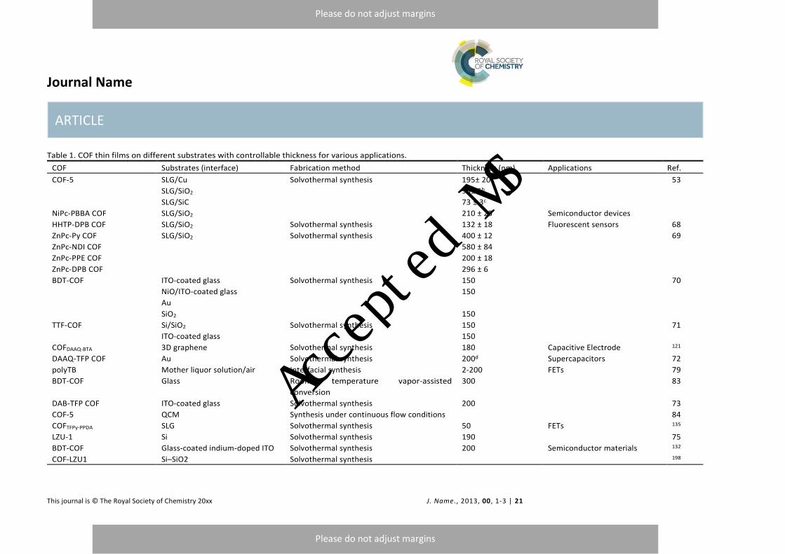
Journal Name
ARTICLE
This journal is © The Royal Society of Chemistry 20xx J. Name., 2013, 00, 1-3 | 21
Please do not adjust margins
Please do not adjust margins
Table 1. COF thin films on different substrates with controllable thickness for various applications.
COF Substrates (interface) Fabrication method Thickness (nm) Applications Ref.
COF-5 SLG/Cu Solvothermal synthesis 195± 20a 53
SLG/SiO2 95± 5b
SLG/SiC 73 ± 3c
NiPc-PBBA COF SLG/SiO2 210 ± 25 Semiconductor devices
HHTP-DPB COF SLG/SiO2 Solvothermal synthesis 132 ± 18 Fluorescent sensors 68
ZnPc-Py COF SLG/SiO2 Solvothermal synthesis 400 ± 12 69
ZnPc-NDI COF 580 ± 84
ZnPc-PPE COF 200 ± 18
ZnPc-DPB COF 296 ± 6
BDT-COF ITO-coated glass Solvothermal synthesis 150 70
NiO/ITO-coated glass 150
Au
SiO2 150
TTF-COF Si/SiO2 Solvothermal synthesis 150 71
ITO-coated glass 150
COFDAAQ-BTA 3D graphene Solvothermal synthesis 180 Capacitive Electrode 121
DAAQ-TFP COF Au Solvothermal synthesis 200d Supercapacitors 72
polyTB Mother liquor solution/air Interfacial synthesis 2-200 FETs 79
BDT-COF Glass Room temperature vapor-assisted
conversion
300 83
DAB-TFP COF ITO-coated glass Solvothermal synthesis 200 73
COF-5 QCM Synthesis under continuous flow conditions 84
COFTFPy-PPDA SLG Solvothermal synthesis 50 FETs 135
LZU-1 Si Solvothermal synthesis 190 75
BDT-COF Glass-coated indium-doped ITO Solvothermal synthesis 200 Semiconductor materials 132
COF-LZU1 Si–SiO2 Solvothermal synthesis 198
Accepted MS
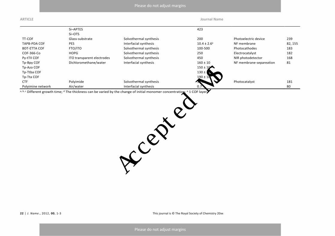
ARTICLE Journal Name
22 | J. Name., 2012, 00, 1-3 This journal is © The Royal Society of Chemistry 20xx
Please do not adjust margins
Please do not adjust margins
Si–APTES 423
Si–OTS
TT-COF Glass-substrate Solvothermal synthesis 200 Photoelectric device 239
TAPB-PDA COF PES Interfacial synthesis 10.4 ± 2.6e NF membrane 82, 155
BDT-ETTA COF FTO/ITO Solvothermal synthesis 100-500 Photocathodes 183
COF-366-Co HOPG Solvothermal synthesis 250 Electrocatalyst 182
Py-tTII COF ITO transparent electrodes Solvothermal synthesis 450 NIR photodetector 168
Tp-Bpy COF Dichloromethane/water Interfacial synthesis 160 ± 10 NF membrane-separeation 81
Tp-Azo COF 150 ± 10
Tp-Ttba COF 130 ± 10
Tp-Tta COF 190 ± 10
CTF Polyimide Solvothermal synthesis 15.1 Photocatalyst 181
Polyimine network Air/water Interfacial synthesis 0.7 80 a, b, c Different growth time; d The thickness can be varied by the change of initial monomer concentration; e 1 COF layer.
Accepted MS

Journal Name ARTICLE
This journal is © The Royal Society of Chemistry 20xx J. Name., 2013, 00, 1-3 | 23
Please do not adjust margins
Please do not adjust margins
Table 2. Free-standing COF thin films with different thickness for various applications.
COF Fabrication methods Thickness (nm) Applications Ref.
COF-8 Solvent-assisted exfoliation 4-10 59 CMP-0 Solvent-assisted exfoliation 2.4 ± 0.2a 85 COF-43 Solvent-assisted exfoliation 1.32 ± 0.37 86 TpPa Mechanical delamination 3-10 94 TpBD COFBDBA-TPTC Self-exfoliation method 0.75 106 COFBPDBA-TPTC 0.72 TpTGxb Self-exfoliation method 2-5 iCONs@Polysulfone (PSF) MMMs 107 DaTp Chemical exfoliation 5-6c 101 DAAQ-ECOF Mechanical delamination 3-5 Cathode Materials for Lithium-Ion Batteries 240 TpASH Chemical exfoliation 15 Drug delivery 5 COF (melamine-OPA) Mechanical delamination TPU/COFs Nanocomposites 97 TPA-COF Solvent-assisted exfoliation 3.5 ± 0.3 DNA detection 87 TpBDH Solvent-assisted exfoliation 1.5-5.1 177 TfpBDH Chemical sensing COF-1 Solvent-assisted exfoliation 0.5 Molecular sieving membranes 88
a After 120 min sonication; b X = Cl-, Br-, I-; c Medium DaTp-CONs concentration.
Accepted MS

ARTICLE Journal Name
24 | J. Name., 2012, 00, 1-3 This journal is © The Royal Society of Chemistry 20xx
Please do not adjust margins
Please do not adjust margins
Fig. 1 Selected examples of existing COFs with different covalent linkages. (a) Boron-containing COF-5. Reproduced with permission from ref. 30. Copyright 2005, American Association for the Advancement of Science. (b) Imine-linked COF-300. Reproduced with permission from ref. 31. Copyright 2009, American Chemical Society. (c) Hydrazine-linked COF-42. Reproduced with permission from ref. 36. Copyright 2011, American Chemical Society. (d) Keto-enol-linked COF TpPa-1. Reproduced with permission from ref. 37. Copyright 2012, American Chemical Society. (e) Azine-linked Py-Azine COF. Reproduced with permission from ref. 51. Copyright 2013, American Chemical Society. (f) NTU-COF-1 with two types of covalent bonds. Reproduced with permission from ref. 46. Copyright 2015, American Chemical Society.
Accepted MS
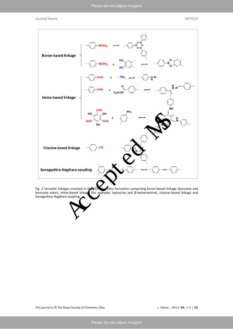
Journal Name ARTICLE
This journal is © The Royal Society of Chemistry 20xx J. Name., 2013, 00, 1-3 | 25
Please do not adjust margins
Please do not adjust margins
Fig. 2 Versatile linkages involved in the COF thin films formation comprising boron-based linkage (boroxine and boronate ester), imine-based linkage (for example, hydrazine and β-ketoenamine), triazine-based linkage and Sonogashira-Hagihara coupling.
Accepted MS

ARTICLE Journal Name
26 | J. Name., 2012, 00, 1-3 This journal is © The Royal Society of Chemistry 20xx
Please do not adjust margins
Please do not adjust margins
Fig. 3 Building blocks bearing catechol, boronic acid, aldehyde, amine and other units involved in the COF thin films formation.
Accepted MS

Journal Name ARTICLE
This journal is © The Royal Society of Chemistry 20xx J. Name., 2013, 00, 1-3 | 27
Please do not adjust margins
Please do not adjust margins
Fig. 4 (a) Schematic illustration of the solvothermal synthesis of COF-5 thin films. (b) X-ray scattering data of COF-5 powder (inset: schematic of randomly oriented COF-5 grains in the powder). (b) GID data from a COF-5 film on SLG/Cu (inset: schematic of oriented COF-5 grains in the film. (c) Top-view SEM image of the COF-5 thin film. Reproduced with permission from ref. 53. Copyright 2011, American Association for the Advancement of Science. (d) Cross-section SEM image of the BDT-COF thin film on ITO-coated glass. (e) Top-view SEM image of the BDT-COF thin film on ITO-coated glass. Reproduced with permission from ref. 70. Copyright 2014, American Chemical Society. (f) Top-view SEM image of the DAB-TFP COF thin film on ITO-coated glass. (g) Cross-section SEM image of the DAB-TFP COF thin film on ITO-coated glass. Reproduced with permission from ref. 73. Copyright 2016, Royal Society of Chemistry.
Accepted MS

ARTICLE Journal Name
28 | J. Name., 2012, 00, 1-3 This journal is © The Royal Society of Chemistry 20xx
Please do not adjust margins
Please do not adjust margins
Fig. 5 (a) Schematic illustration of the interfacial synthesis of Tp-Bpy COF thin films. (b) AA stacking mode of Tp-Bpy COF. (c) SEM image of Tp-Bpy COF thin films. (d) AFM image of Tp-Bpy COF thin films. Reproduced with permission from ref. 81. Copyright 2014, American Chemical Society.
Accepted MS
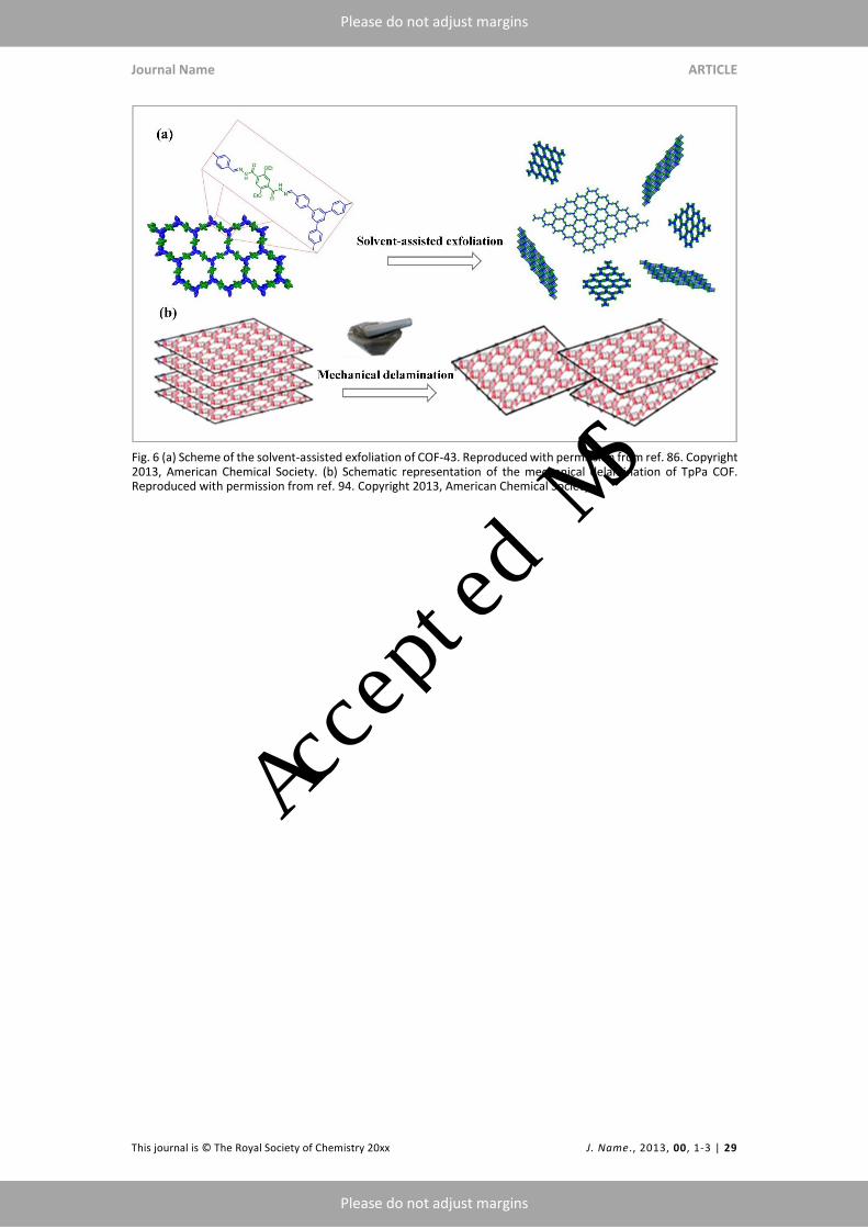
Journal Name ARTICLE
This journal is © The Royal Society of Chemistry 20xx J. Name., 2013, 00, 1-3 | 29
Please do not adjust margins
Please do not adjust margins
Fig. 6 (a) Scheme of the solvent-assisted exfoliation of COF-43. Reproduced with permission from ref. 86. Copyright 2013, American Chemical Society. (b) Schematic representation of the mechanical delamination of TpPa COF. Reproduced with permission from ref. 94. Copyright 2013, American Chemical Society
Accepted MS

ARTICLE Journal Name
30 | J. Name., 2012, 00, 1-3 This journal is © The Royal Society of Chemistry 20xx
Please do not adjust margins
Please do not adjust margins
Fig. 7 (a) AFM image of TPA-COF nanosheets with the thickness indicated. (2) TEM image of TPA-COF nanosheets with an inset photograph of the Tyndall effect of the TPA-COF nanosheets suspension. (c) Low-dose high-resolution motion-corrected TEM image of the TPA-COF nanosheets with an insert of characterization of the fast Fourier transform (FFT). (d) Enlarged HRTEM image with an insert of simulated HRTEM image. Reproduced with permission from ref. 87. Copyright 2017, American Chemical Society. (e) HRTEM image of TpPa-2 before grinding. (f) HRTEM image of TpPa-2 after grinding. Reproduced with permission from ref. 94. Copyright 2013, American Chemical Society.
Accepted MS
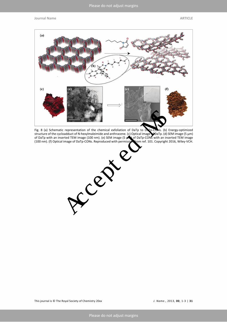
Journal Name ARTICLE
This journal is © The Royal Society of Chemistry 20xx J. Name., 2013, 00, 1-3 | 31
Please do not adjust margins
Please do not adjust margins
Fig. 8 (a) Schematic representation of the chemical exfoliation of DaTp to DaTp-CONs. (b) Energy-optimized structure of the cycloadduct of N-hexylmaleimide and anthracene. (c) Optical image of DaTp. (d) SEM image (5 μm) of DaTp with an inserted TEM image (100 nm). (e) SEM image (5 μm) of DaTp-CONs with an inserted TEM image (100 nm). (f) Optical image of DaTp-CONs. Reproduced with permission from ref. 101. Copyright 2016, Wiley-VCH.
Accepted MS
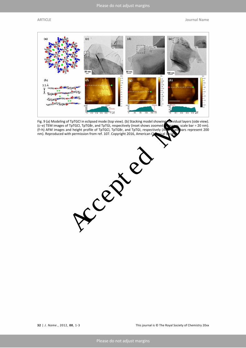
ARTICLE Journal Name
32 | J. Name., 2012, 00, 1-3 This journal is © The Royal Society of Chemistry 20xx
Please do not adjust margins
Please do not adjust margins
Fig. 9 (a) Modeling of TpTGCl in eclipsed mode (top view). (b) Stacking model showing individual layers (side view). (c−e) TEM images of TpTGCl, TpTGBr, and TpTGI, respectively (inset shows zoomed in images; scale bar = 20 nm). (f−h) AFM images and height profile of TpTGCl, TpTGBr, and TpTGI, respectively (AFM scale bars represent 200 nm). Reproduced with permission from ref. 107. Copyright 2016, American Chemical Society.
Accepted MS
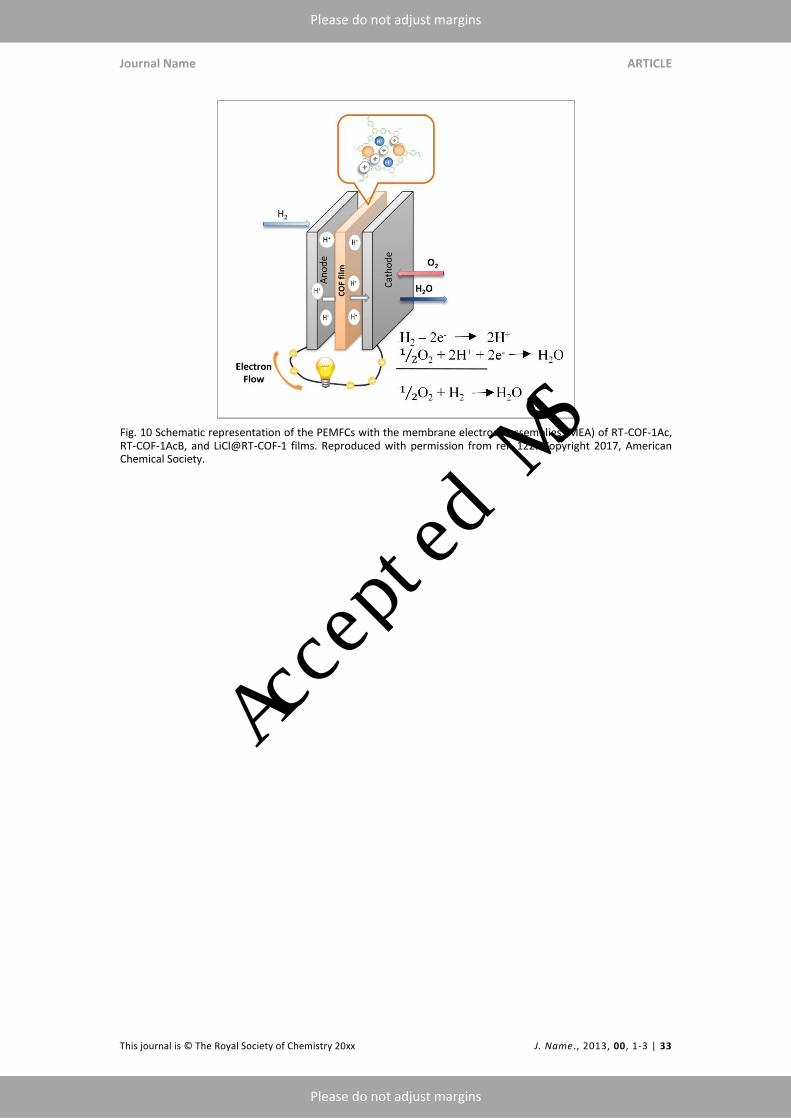
Journal Name ARTICLE
This journal is © The Royal Society of Chemistry 20xx J. Name., 2013, 00, 1-3 | 33
Please do not adjust margins
Please do not adjust margins
Fig. 10 Schematic representation of the PEMFCs with the membrane electrode assemblies (MEA) of RT-COF-1Ac, RT-COF-1AcB, and LiCl@RT-COF-1 films. Reproduced with permission from ref. 122. Copyright 2017, American Chemical Society.
Accepted MS
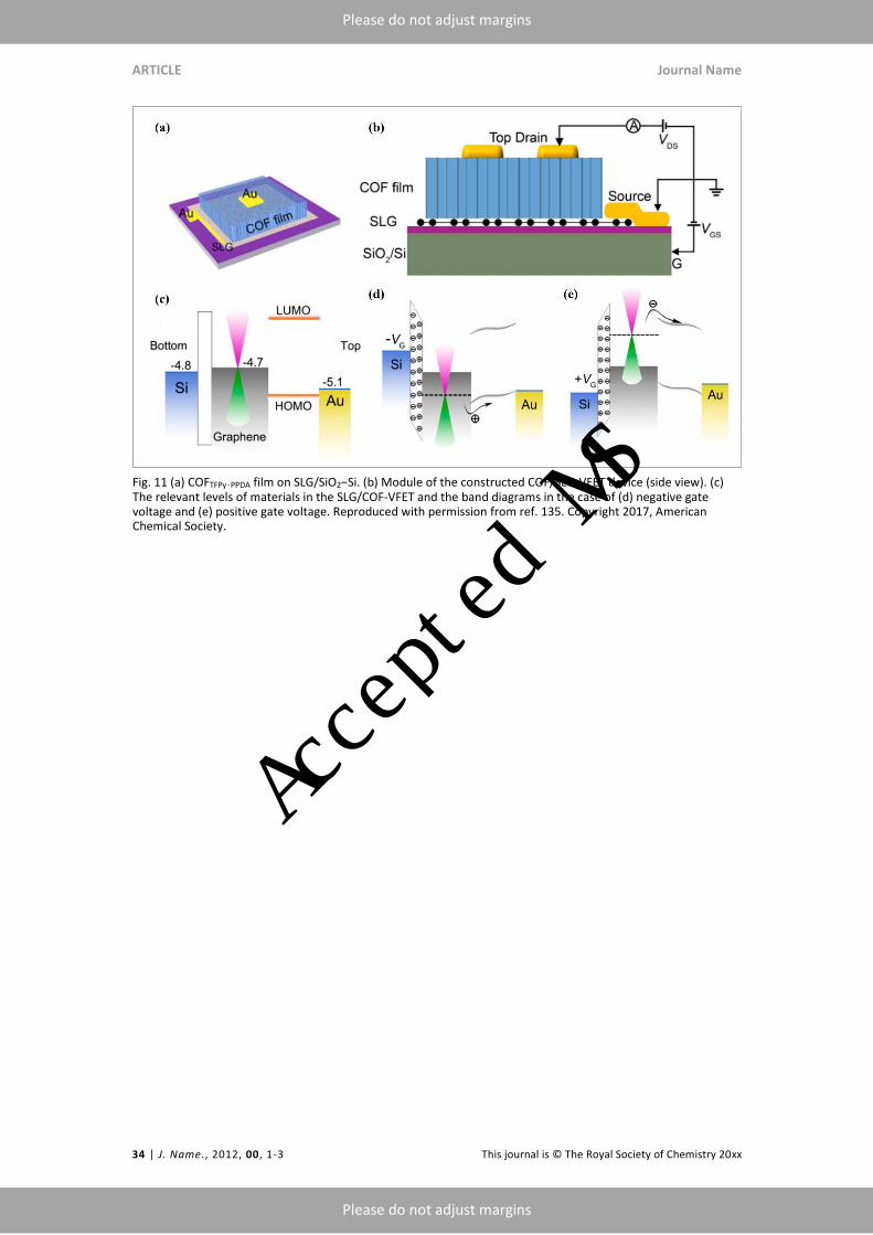
ARTICLE Journal Name
34 | J. Name., 2012, 00, 1-3 This journal is © The Royal Society of Chemistry 20xx
Please do not adjust margins
Please do not adjust margins
Fig. 11 (a) COFTFPy‑PPDA film on SLG/SiO2−Si. (b) Module of the constructed COF/SLG-VFET device (side view). (c) The relevant levels of materials in the SLG/COF-VFET and the band diagrams in the case of (d) negative gate voltage and (e) positive gate voltage. Reproduced with permission from ref. 135. Copyright 2017, American Chemical Society.
Accepted MS
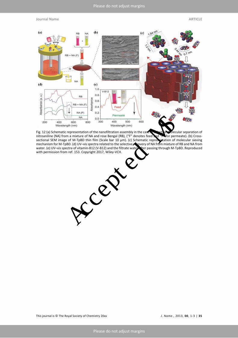
Journal Name ARTICLE
This journal is © The Royal Society of Chemistry 20xx J. Name., 2013, 00, 1-3 | 35
Please do not adjust margins
Please do not adjust margins
Fig. 12 (a) Schematic representation of the nanofiltration assembly in the case of selective molecular separation of nitroaniline (NA) from a mixture of NA and rose Bengal (RB), (“F” denotes feed and “P” for permeate). (b) Cross-sectional SEM image of M-TpBD thin film (Scale bar 10 μm). (c) Schematic representation of molecular sieving mechanism for M-TpBD. (d) UV–vis spectra related to the selective recovery of NA from mixture of RB and NA from water. (e) UV–vis spectra of vitamin-B12 (V-B12) and the filtrate water after passing through M-TpBD. Reproduced with permission from ref. 153. Copyright 2017, Wiley-VCH.
Accepted MS
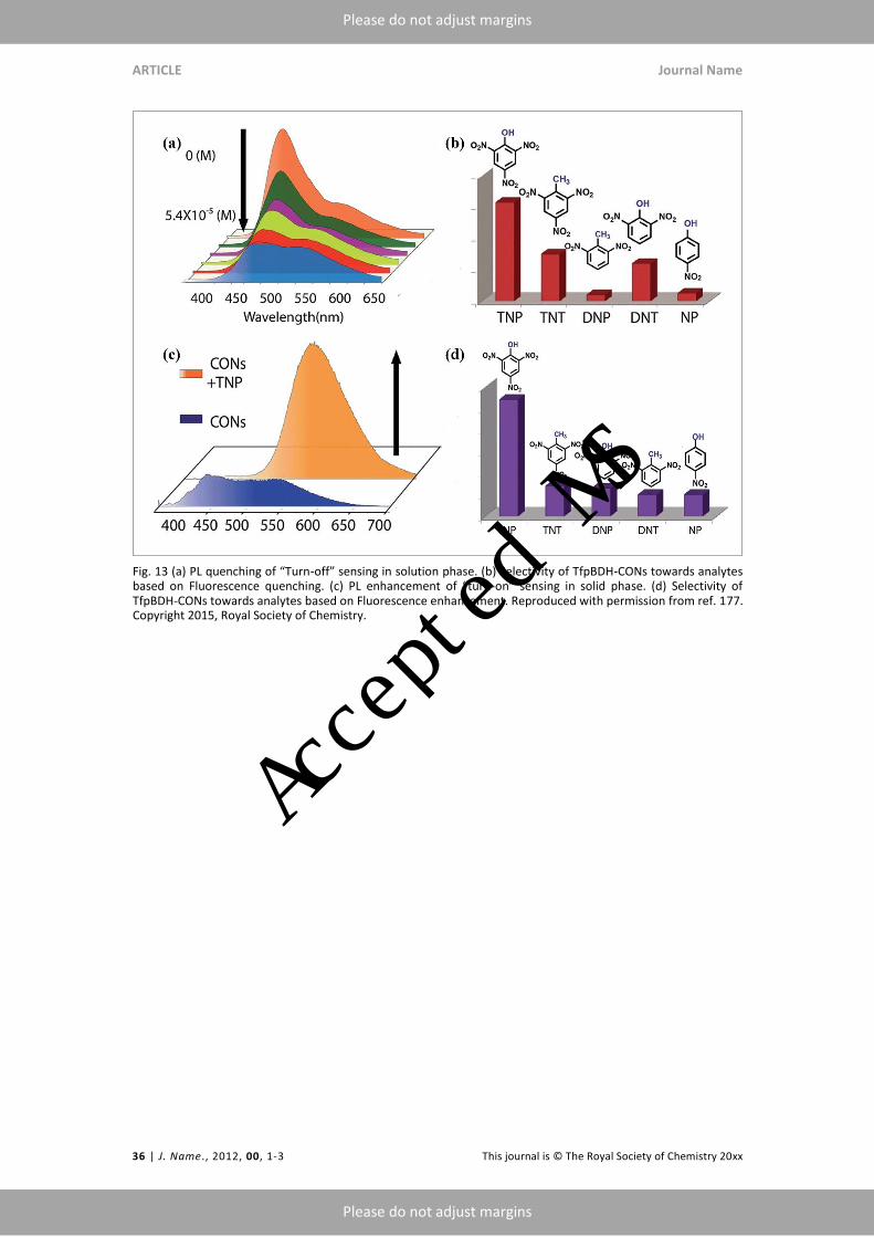
ARTICLE Journal Name
36 | J. Name., 2012, 00, 1-3 This journal is © The Royal Society of Chemistry 20xx
Please do not adjust margins
Please do not adjust margins
Fig. 13 (a) PL quenching of “Turn-off” sensing in solution phase. (b) Selectivity of TfpBDH-CONs towards analytes based on Fluorescence quenching. (c) PL enhancement of “turn-on” sensing in solid phase. (d) Selectivity of TfpBDH-CONs towards analytes based on Fluorescence enhancement. Reproduced with permission from ref. 177. Copyright 2015, Royal Society of Chemistry.
Accepted MS

Journal Name ARTICLE
This journal is © The Royal Society of Chemistry 20xx J. Name., 2013, 00, 1-3 | 37
Please do not adjust margins
Please do not adjust margins
Fig. 14 (a) Structure of Cobalt-porphyrin based COF backbone. (b) Schematic illustration of electrolysis cell electrocatalytic CO2 reduction. Reproduced with permission from ref. 182. Copyright 2018, American Chemical Society.
Accepted MS