Recent Hydroform and Flexform Development
13
1 © 2016 Quintus Technologies Document no SE037406 Revision 1 Page 1(3) Abstract: In Flexform, sheet metal is formed over one rigid, shape-defining tool half by a flexible rubber diaphragm supported by hydraulic pressure. The technology has been the preferred sheet metal fabrication method within the aerospace airframe industry for decades. The automotive industry has more recently successfully adopted the technology within prototyping and low volume production. The relatively recent introduction of trustworthy forming simulation software also for hydroforming or Flexform has taken the technology to a new level. The elimination of the historical dependency of skilled operators and costly trial and errors has provided a new era for the technology. The combi- nation of modern, efficient tool design, combined with high pressure has proven to cut development time, labor hours and labor dependency dramatically. The global trend within main aerospace and automotive OEM’s to outsource fabrication and part supply has put new demands also to the hydroforming process providers. In essence, lower tier suppliers, require smaller sized, efficient equipment at affordable investment levels. Keywords: Recent Hydroform and Flexform Development White paper by Sture Olsson, Quintus Technologies. Västerås, Sweden, April 2016. The Principle of Flexform Hydroform, flexform, metal forming, prototyping, airframes, quintus, rapid prototyping The blank is positioned on the tool Finished part after decompression Oil is pumped in and wraps the blank around the tool Pressure medium, oil Flexible rubber diaphragm Blank holder Sheet metal part Cutting edge One single rigid tool half Undercut Blank holder
Transcript of Recent Hydroform and Flexform Development

1© 2016 Quintus Technologies
Document no SE037406Revision 1 Page 1(3)
Abstract:In Flexform, sheet metal is formed over one rigid, shape-defining tool half by a flexible rubber diaphragm supported by hydraulic pressure.
The technology has been the preferred sheet metal fabrication method within the aerospace airframe industry for decades. The automotive industry has more recently successfully adopted the technology within prototyping and low volume production.
The relatively recent introduction of trustworthy forming simulation software also for hydroforming or Flexform has taken the technology to a new level. The elimination of the historical dependency of skilled operators and costly trial and errors has provided a new era for the technology. The combi-nation of modern, efficient tool design, combined with high pressure has proven to cut development time, labor hours and labor dependency dramatically.
The global trend within main aerospace and automotive OEM’s to outsource fabrication and part supply has put new demands also to the hydroforming process providers. In essence, lower tier suppliers, require smaller sized, efficient equipment at affordable investment levels.
Keywords:
Recent Hydroform and Flexform DevelopmentWhite paper by Sture Olsson, Quintus Technologies. Västerås, Sweden, April 2016.
The Principle of Flexform
Hydroform, flexform, metal forming, prototyping, airframes, quintus, rapid prototyping
The blank is positioned on the tool
Finished part after decompression
Oil is pumped in and wrapsthe blank around the tool
Pressure medium, oil
Flexible rubber diaphragm
Blank holder
Sheet metal part
Cutting edge
One single rigid tool halfUndercut
Blank holder

2© 2016 Quintus Technologies
IntroductionIn the literature and in the industry the hydroform process refers to a wide variety of technologies. All processes are using a liquid as a processing media, some processes exposing the liquid into direct contact with the metal to be formed. Some technologies ensuring to separate the pressure media from the sheet metal blank.
This paper will in particular concentrate at a sheet forming technology where a flexible rubber dia-phragm seals the pressure liquid inside the pressure vessel, ensuring the sheet metal to only face the surface of the rubber diaphragm, also called the bladder.
The technology may be operated with a solid block tool, a cavity tool or an expansion forming tool. The technology may also be operated with a movable male punch, pushed through a draw ring against the flexible rubber diaphragm, often also referred to as hydro-mechanical forming, or deep-drawing. The technology will in this paper be referred to as Flexform and Flexform deep-drawing.
The technology is well established within the aerospace industry since decades, but is also well estab-lished within automotive prototyping and within the special vehicle supply chain.
The Flexform technology provide the flexibility of several forming methods. A comparison of different flexible forming methods.
3© 2016 Quintus Technologies
Deep draw2nd generation
2013
Deep drawpress
1965
Tool support
2012
Fluid Cell Circular
1999
Fluid Cell 2nd generation
1985
Fluid Cell 1st generation
1973
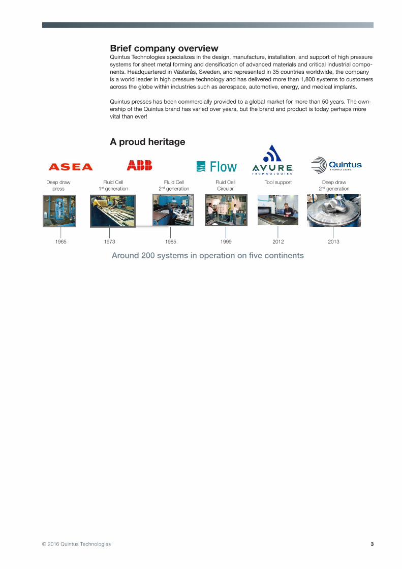
A proud heritage
Around 200 systems in operation on five continents
Brief company overviewQuintus Technologies specializes in the design, manufacture, installation, and support of high pressure systems for sheet metal forming and densification of advanced materials and critical industrial compo-nents. Headquartered in Västerås, Sweden, and represented in 35 countries worldwide, the company is a world leader in high pressure technology and has delivered more than 1,800 systems to customers across the globe within industries such as aerospace, automotive, energy, and medical implants.
Quintus presses has been commercially provided to a global market for more than 50 years. The own-ership of the Quintus brand has varied over years, but the brand and product is today perhaps more vital than ever!
4© 2016 Quintus Technologies
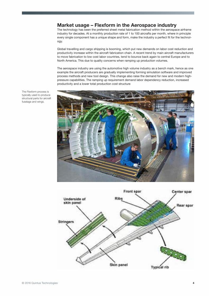
Market usage – Flexform in the Aerospace industryThe technology has been the preferred sheet metal fabrication method within the aerospace airframe industry for decades. At a monthly production rate of 1 to 100 aircrafts per month, where in principle every single component has a unique shape and form, make the industry a perfect fit for the technol-ogy.
Global travelling and cargo shipping is booming, which put new demands on labor cost reduction and productivity increase within the aircraft fabrication chain. A recent trend by main aircraft manufacturers to move fabrication to low cost labor countries, tend to bounce back again to central Europe and to North America. This due to quality concerns when ramping up production volumes.
The aerospace industry are using the automotive high volume industry as a bench mark, hence as one example the aircraft producers are gradually implementing forming simulation software and improved process methods and new tool design. This change also raise the demand for new and modern high-pressure capabilities. The ramping up requirement demand labor dependency reduction, increased productivity and a lower total production cost structure
The Flexform process is typically used to produce structural parts for aircraft fuselage and wings.
5© 2016 Quintus Technologies
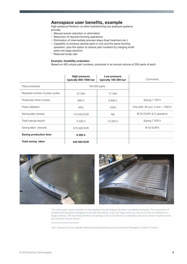
Aerospace user benefits, exampleHigh-pressure Flexform vs other hydroforming low pressure systems provide:• Manual rework reduction or elimination• Reduction of required forming operations• Elimination of intermediate process steps (heat treatment etc.)• Capability to produce several parts in one and the same forming operation, plus the option to reduce part numbers by merging small parts into large sections • Reduced scrap rate
Example, feasibility evaluationBased on 400 unique part numbers, produced in an annual volume of 250 parts of each:
Parts produced 100 000 parts
Required number of press cycles
Production time in press
Press utilization
Saving labor (press)
Total manual rework
Saving labor (rework)
Saving production time
Total saving labor
High pressure typically 600-1000 bar
27 000
900 h
45%
170 000 EUR
4 200 h
375 000 EUR
9 200 h
545 000 EUR
Low pressure typically 100-300 bar
77 000
2 600 h
135%
NA
12 000 h
Comments
Saving 1 700 h
One shift: 48 w/y; 5 d/w = 1920 h
@ 50 EUR/h & 2 operators
Saving 7 500 h
@ 50 EUR/h
“For many parts, hand correction of incompletely-formed shapes has been completely eliminated. The occurrence of wrinkles and excessive springback is far less than before. Even very large parts can now be formed to tolerance in a single pressing. We have documented cost savings of 25 to 42 percent on sampled parts due to fewer required cycles and reduced manual rework.”
Jean-Jacques Rousse, Metallic Manufacturing Engineering and Development Manager at Daher in France
6© 2016 Quintus Technologies
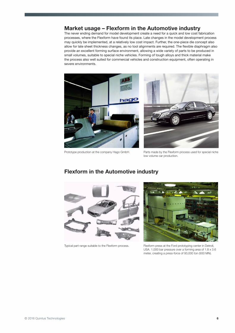
Market usage – Flexform in the Automotive industryThe never ending demand for model development create a need for a quick and low cost fabrication processes, where the Flexform have found its place. Late changes in the model development process may quickly be implemented, at a relatively low cost impact. Further, the one-piece die concept also allow for late sheet thickness changes, as no tool alignments are required. The flexible diaphragm also provide an excellent forming surface environment, allowing a wide variety of parts to be produced in small volumes, suitable to special niche vehicles. Forming of tough alloys and thick material make the process also well suited for commercial vehicles and construction equipment, often operating in severe environments.
Flexform in the Automotive industry
Prototype production at the company Hago GmbH. Parts made by the Flexform process used for special niche low volume car production.
Typical part range suitable to the Flexform process. Flexform press at the Ford prototyping center in Detroit, USA. 1,000 bar pressure over a forming area of 1.8 x 3.6 meter, creating a press-force of 93,000 ton (930 MN).
7© 2016 Quintus Technologies
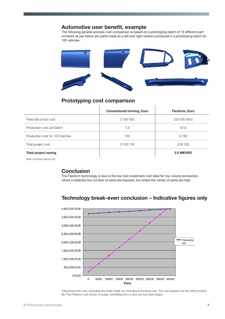
Automotive user benefit, exampleThe following general process cost comparison is based on a prototyping batch of 13 different part numbers as per below (six parts made as a left and right version) produced in a prototyping batch for 100 vehicles.
Fixed die or tool cost
Production cost per batch
Production cost for 100 batches
Total project cost
Total project saving
Note, indicative figures only.
Conventional forming, Euro
3 700 000
7,3
730
3 700 730
Flexform, Euro
220 000 (6%)
97,8
9 780
229 780
3.5 MEURO
Prototyping cost comparison
ConclusionThe Flexform technology is due to the low tool investment cost ideal for low volume production, where a relatively low number of parts are required, but where the variety of parts are high.
Technology break-even conclusion – Indicative figures only
Total production cost, excluding the sheet metal, but including the tooling cost. The cost spread over the entire product life. The Flexform cost shown in purple, benefitting from a very low tool cost impact.

8© 2016 Quintus Technologies
Flexform technology developmentThe technology has been the preferred sheet metal fabrication method The usage of only one tool half, in many cases also combined with the ability to use extremely low cost tool material, such as bakelite and hardwood, allow for low cost and rapid prototype fabrication.
Introduction of forming simulation softwareThe relatively recent introduction of trustworthy forming simulation software also for hydroforming or Flexform has taken the technology to a new level. The elimination of the historical dependency of skilled operators and costly trial and errors has provided a new era for the technology. The combina-tion of modern, efficient tool design, combined with high pressure has proven to cut development time, labor hours and labor dependency dramatically.
Modern tool design, combined with simulation capabilities, has paved the way for the introduction of fairly simple draw-dams, or blank holders. The combination of the pressure and the flexible forming process hereby allow for better material stretch control and thereby a better ability to for example overcome wrinkling in stretch flanges, typical for many airframe parts. Modern tool design may as another example also enable trimming and cutting of the metal in the single die Flexform technology.
The relatively recent introduction of simulation soft-ware improve the process development.
Trimming and cutting may also be used, still using the simple one-die Flexform technology
High-pressure, combined with the flexible diaphragm technology allow for introduction of simple blank holding tool technologies.

9© 2016 Quintus Technologies
The pressure impact on the formingThe quality of the forming is to a large degree related to the pressure level used. Users frequently report successful reduction of labor hours being reduced by 20-50%, when moving from low pressure (typically 100-200 bar) to high-pressure (typically 600-1000 bar). In addition to these figures, the elimi-nation of several process steps shall be added, such as required intermediate heat treatments, typical when operating low pressure forming processes. The spring back repeatability is also improved at high pressure, allowing for spring-back compensation to be designed into the forming tools.
The pressure impact of the “free forming radii” illustrated both as a theoretical graph and in actual formed metal strips (in Al 2024-0).
High forming pressure
High-pressure equipmentThe pressure level is vital to achieve the forming parameters required. From an equipment engineer-ing point of view the combination of a high pressure, the requirement of a large forming area and the number of pressing cycles required vs. the life of a pressure vessel is a challenge! The technology presented in this paper is based on a technical solution designed to overcome the equipment fatigue challenge, where a pre-stress is created in the main pressure vessel (or press frame) by layers and lay-ers of steel wire, wrapped around the pressure unit.
Nearly 2,000 wire-wound high-pressure vessels and press-frames has successfully been provided to a global industry (by Quintus Technologies) within a commercial time-frame of some 50 years. Most equipment are still in production and several presses have reached a cycle count of more than 1 million cycle. Hence, it is commercially well proven that a viable design exist to create large forming areas, combined with high pressure and millions of forming cycles.

10© 2016 Quintus Technologies
A pre-stress technology, where layers and layers of steel wire are wound around a pressure vessel, is used to manufacture long lasting high-pressure systems.
A 93,000 ton press-force Flexform press at Midlands Engineering (Rover) in the UK.
Available type of equipments
Fluid cell presses with rectangular forming tablesFlexform, or fluid cell presses are available in two types, equipped with rectangular forming tables or circular forming tables.
Presses with rectangular shaped forming tables, may also be operated with several forming tools, allowing forming of all parts in one and the same forming operation. Tool types may be block tools, cavity tools and expansion forming tools. The forming area of commercially available fluid cell presses range from ~0.5x1 meter up to 2 x 4 meter. Pressure capacity from a few hundred bar up to 1,400 bar.
Low cost tool material like hard-wood may suit a rapid prototyping demand.
A 1,400 bar Flexform system at Bombardier, Northern Ireland, equipped with a loading pallet system for high-volume production.
11© 2016 Quintus Technologies
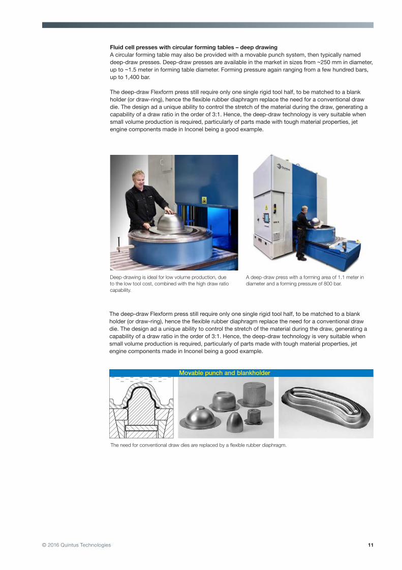
Fluid cell presses with circular forming tables – deep drawingA circular forming table may also be provided with a movable punch system, then typically named deep-draw presses. Deep-draw presses are available in the market in sizes from ~250 mm in diameter, up to ~1.5 meter in forming table diameter. Forming pressure again ranging from a few hundred bars, up to 1,400 bar.
The deep-draw Flexform press still require only one single rigid tool half, to be matched to a blank holder (or draw-ring), hence the flexible rubber diaphragm replace the need for a conventional draw die. The design ad a unique ability to control the stretch of the material during the draw, generating a capability of a draw ratio in the order of 3:1. Hence, the deep-draw technology is very suitable when small volume production is required, particularly of parts made with tough material properties, jet engine components made in Inconel being a good example.
Deep-drawing is ideal for low volume production, due to the low tool cost, combined with the high draw ratio capability.
A deep-draw press with a forming area of 1.1 meter in diameter and a forming pressure of 800 bar.
The deep-draw Flexform press still require only one single rigid tool half, to be matched to a blank holder (or draw-ring), hence the flexible rubber diaphragm replace the need for a conventional draw die. The design ad a unique ability to control the stretch of the material during the draw, generating a capability of a draw ratio in the order of 3:1. Hence, the deep-draw technology is very suitable when small volume production is required, particularly of parts made with tough material properties, jet engine components made in Inconel being a good example.
The need for conventional draw dies are replaced by a flexible rubber diaphragm.
12© 2016 Quintus Technologies
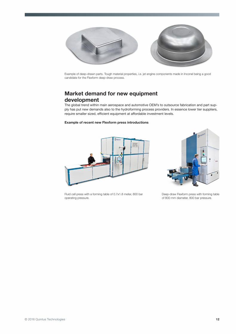
Market demand for new equipment developmentThe global trend within main aerospace and automotive OEM’s to outsource fabrication and part sup-ply has put new demands also to the hydroforming process providers. In essence lower tier suppliers, require smaller sized, efficient equipment at affordable investment levels. Example of recent new Flexform press introductions
Example of deep-drawn parts. Tough material properties, i.e. jet engine components made in Inconel being a good candidate for the Flexform deep-draw process.
Deep-draw Flexform press with forming table of 800 mm diameter, 800 bar pressure.
Fluid cell press with a forming table of 0.7x1.8 meter, 800 bar operating pressure.

13© 2016 Quintus Technologies
Summary and conclusionIn Flexform, sheet metal is formed over one rigid, shape-defining tool half by a flexible rubber dia-phragm supported by hydraulic pressure. The technology may be operated with a solid block tool, a cavity tool or an expansion forming tool. The technology may also be operated with a movable male punch, pushed through a draw ring against the flexible rubber diaphragm.
The technology has been the preferred sheet metal fabrication method within the aerospace airframe industry for decades. The automotive industry have more recently successfully adopted the technol-ogy within prototyping and low volume production.
The relatively recent introduction of trustworthy forming simulation software also for hydroforming or Flexform has taken the technology to a new level. The elimination of the historical dependency of skilled operators and costly trial and errors has provided a new era for the technology. The combi-nation of modern, efficient tool design, combined with high pressure has proven to cut development time, labor hours and labor dependency dramatically.
The global trend within main aerospace and automotive OEM’s to outsource fabrication and part supply has put new demands also to the hydroforming process providers. In essence, small sized, lower tier suppliers, require smaller sized, efficient equipment at affordable investment levels.