Recent developments in the design of cold-formed steel members and structures
7
Recent developments in the design of cold-formed steel members and structures M. Macdonald a, , M.A. Heiyantuduwa a , J. Rhodes b a School of Engineering, Science and Design, Glasgow Caledonian University, Cowcaddens Road, Glasgow G4 0BA, Scotland b Department of Mechanical Engineering, University of Strathclyde, 75 Montrose Street, Glasgow G1 1XJ, Scotland article info Available online 11 April 2008 Keywords: Design Buckling Beams Columns Cold-formed steel abstract Cold-formed steel members and structures are extremely widespread in use at the present time. The design analysis of such structures is often complex, as their behaviour can be influenced by effects, which arise due to the slenderness of members, walls and cross-sections. Prime among these effects are the various types of buckling which can occur, and which may interact with each other to promote failure at loads substantially less than those, which would be obtained in the absence of these effects. The complications induced by such effects must be taken into account in design, if the potential benefits offered by the use of such members are to be realised, and in recent design specifications this has been realised. In this paper the main types of cold-formed steel members are described, the particular characteristics affecting their design are discussed, as are the ways in which design specifications deal with these characteristics. Crown Copyright & 2008 Published by Elsevier Ltd. All rights reserved. 1. Introduction Cold-formed steel sections, i.e. structural sections manufac- tured from sheet steel by cold rolling, brake pressing or folding, have been around for many decades now. However, the growth in structural use and understanding of the behaviour of structures made in this way started during the Second World War and the first design specification for this type of construction was produced in USA in 1946 [1]. The first UK specification was produced in 1961 [2], although a proposed specification [3] had been published some 10 years earlier. The 1970s saw an upsurge in interest in this field in Europe, and in the 1980s new UK codes and European Recommendations for design in cold-formed steel were produced [4,5] as well as a new American code. This interest has continued since then, and the first Eurocode dealing with cold-formed steel was published in the 1990s [6]. Particular types of cold-formed steel structures have their own inherent design complexities, and new design specifications have been produced in recent years dealing specifically with stainless steel [7] and storage racking [8]. Since about 1980, there has also been a progressive increase in the strength of steel used in the manufacture of cold-formed sections. Prior to this period the type of steel most widely used in the construction industry was of about 200 MN/m 2 yield strength whereas at the present time many companies are producing members with about 400 MN/m 2 yield strength. Indeed, there has recently been substantial use in Australia of cold-formed tubes of yield strength 1350 MN/m 2 . The major structural advantage of cold-formed steel members lies with the ‘thinness’ of the material, which can be used, leading to an extremely light-weight construction. This, combined with the trend towards using higher strength steel, promotes the occurrence of failure modes, which do not arise, or are rare in occurrence, in conventional steel structures. Thus, the advantages which can be gained by the use of cold forming are bought at the expense of the requirement to use increased sophistication in the design analysis. Perhaps the major factor, which arises in the design of cold- formed steel members, is the susceptibility of these members to a wide variety of buckling modes. The thin walls of such members are often liable to suffer local buckling in compression, and this must be taken into account in the design of almost any cold- formed steel structural member. Local buckling is stable in the elastic range, and locally buckled members may have substantial post-buckling strength. However, local buckling does modify the behaviour of a member, and the effects of local buckling on member behaviour, and its interaction with other buckling modes, must be considered in design. Another factor, which causes complexity in cold-formed steel design, arises from the fact that cold-formed members, in addition to being thin-walled, are in most cases open sections, and are extremely flexible and weak in resistance to torsion. This brings ARTICLE IN PRESS Contents lists available at ScienceDirect journal homepage: www.elsevier.com/locate/tws Thin-Walled Structures 0263-8231/$ - see front matter Crown Copyright & 2008 Published by Elsevier Ltd. All rights reserved. doi:10.1016/j.tws.2008.01.039 Corresponding author. E-mail address: [email protected] (M. Macdonald). Thin-Walled Structures 46 (2008) 1047–1053
-
Upload
m-macdonald -
Category
Documents
-
view
215 -
download
3
Transcript of Recent developments in the design of cold-formed steel members and structures

ARTICLE IN PRESS
Thin-Walled Structures 46 (2008) 1047– 1053
Contents lists available at ScienceDirect
Thin-Walled Structures
0263-82
doi:10.1
� Corr
E-m
journal homepage: www.elsevier.com/locate/tws
Recent developments in the design of cold-formed steel membersand structures
M. Macdonald a,�, M.A. Heiyantuduwa a, J. Rhodes b
a School of Engineering, Science and Design, Glasgow Caledonian University, Cowcaddens Road, Glasgow G4 0BA, Scotlandb Department of Mechanical Engineering, University of Strathclyde, 75 Montrose Street, Glasgow G1 1XJ, Scotland
a r t i c l e i n f o
Available online 11 April 2008
Keywords:
Design
Buckling
Beams
Columns
Cold-formed steel
31/$ - see front matter Crown Copyright & 20
016/j.tws.2008.01.039
esponding author.
ail address: [email protected] (M. Mac
a b s t r a c t
Cold-formed steel members and structures are extremely widespread in use at the present time. The
design analysis of such structures is often complex, as their behaviour can be influenced by effects,
which arise due to the slenderness of members, walls and cross-sections. Prime among these effects are
the various types of buckling which can occur, and which may interact with each other to promote
failure at loads substantially less than those, which would be obtained in the absence of these effects.
The complications induced by such effects must be taken into account in design, if the potential benefits
offered by the use of such members are to be realised, and in recent design specifications this has been
realised. In this paper the main types of cold-formed steel members are described, the particular
characteristics affecting their design are discussed, as are the ways in which design specifications deal
with these characteristics.
Crown Copyright & 2008 Published by Elsevier Ltd. All rights reserved.
1. Introduction
Cold-formed steel sections, i.e. structural sections manufac-tured from sheet steel by cold rolling, brake pressing or folding,have been around for many decades now. However, the growth instructural use and understanding of the behaviour of structuresmade in this way started during the Second World War and thefirst design specification for this type of construction wasproduced in USA in 1946 [1]. The first UK specification wasproduced in 1961 [2], although a proposed specification [3] hadbeen published some 10 years earlier. The 1970s saw an upsurgein interest in this field in Europe, and in the 1980s new UK codesand European Recommendations for design in cold-formed steelwere produced [4,5] as well as a new American code. This interesthas continued since then, and the first Eurocode dealing withcold-formed steel was published in the 1990s [6]. Particular typesof cold-formed steel structures have their own inherent designcomplexities, and new design specifications have been producedin recent years dealing specifically with stainless steel [7] andstorage racking [8].
Since about 1980, there has also been a progressive increase inthe strength of steel used in the manufacture of cold-formedsections. Prior to this period the type of steel most widely used inthe construction industry was of about 200 MN/m2 yield strength
08 Published by Elsevier Ltd. All
donald).
whereas at the present time many companies are producingmembers with about 400 MN/m2 yield strength. Indeed, there hasrecently been substantial use in Australia of cold-formed tubes ofyield strength 1350 MN/m2.
The major structural advantage of cold-formed steel memberslies with the ‘thinness’ of the material, which can be used, leadingto an extremely light-weight construction. This, combined withthe trend towards using higher strength steel, promotes theoccurrence of failure modes, which do not arise, or are rare inoccurrence, in conventional steel structures. Thus, the advantageswhich can be gained by the use of cold forming are bought at theexpense of the requirement to use increased sophistication in thedesign analysis.
Perhaps the major factor, which arises in the design of cold-formed steel members, is the susceptibility of these members to awide variety of buckling modes. The thin walls of such membersare often liable to suffer local buckling in compression, and thismust be taken into account in the design of almost any cold-formed steel structural member. Local buckling is stable in theelastic range, and locally buckled members may have substantialpost-buckling strength. However, local buckling does modify thebehaviour of a member, and the effects of local buckling onmember behaviour, and its interaction with other buckling modes,must be considered in design.
Another factor, which causes complexity in cold-formed steeldesign, arises from the fact that cold-formed members, in additionto being thin-walled, are in most cases open sections, and areextremely flexible and weak in resistance to torsion. This brings
rights reserved.

ARTICLE IN PRESS
M. Macdonald et al. / Thin-Walled Structures 46 (2008) 1047–10531048
the requirement to ensure that the loading is introduced to suchstructures in such a way that torsional behaviour is minimised,and also introduces the possibility of torsional buckling, torsio-nal–flexural buckling and lateral torsional buckling in cold-formed members.
Another source of complexity is found in the methods used toconnect cold-formed steel members. In comparison with hot-rolled structures, welding is used to a much smaller degree, and aplethora of connection types and methods exist, including the useof bolts, rivets, screws, adhesives, together with a number ofconnection types in which the connection is made by deformingthe materials of adjoining members to form the joints. Connec-tions in cold-formed steel members in the main lack completerigidity, and the semi-rigid nature of the connections can have asubstantial effect on the structural behaviour.
In the following section, the major factors influencing cold-formed steel design are briefly discussed and illustrated. Time andspace limitations are such that only the various buckling modeswill be considered.
2. Cold-formed steel columns
2.1. Local buckling
The propensity for thin-walled structural members to developlocal buckling in the walls is well known, and the dimensionallimits set in cold-formed steel design specifications are such thatlocal buckling could occur in extreme cases under a compressivestress as low as 2–3 MN/m2, i.e. of the order of one hundredth ofthe material elastic limit. It follows that in order to be in any waycompetitive, cold-formed steel members must be designed tomake use of their elastic post-local-buckling capacity, and this istaken for granted in design specifications. The post-local-bucklingbehaviour is generally taken into account in design specificationsusing the effective width approach. In this approach, the largelocal buckling displacements in plate elements in areas far fromcorners are assumed to render these areas incapable of, orineffective in, resisting compression and all compressive load isresisted by effective portions situated adjacent to the corners asillustrated in Fig. 1.
Stress distribution
Effective parts shaded
σ
0
Fig. 1. Stress distribution and effective area.
Plain channel-LocalBuckling
Lipped channBucklin
Fig. 2. Distortional buckling. (a) Plain channel–local buckling, (b) lipped
In most design specifications, the effective widths of com-pressed elements are evaluated using modifications of theexpression given by [9], i.e.
be
b¼
ffiffiffiffiffiffiffisCR
s
r1� 0:2
ffiffiffiffiffiffiffisCR
s
r� �(1)
where be is the effective width of the element, b is the actualwidth of the element, sCR is the critical stress to cause localbuckling and s is the stress acting on the effective parts.
The critical stress to cause local buckling in an elementdepends on the member geometry and varies from section tosection. The British Standard [4] gives graphs and formulaecovering elements in a number of common structural members.For elements in other cross-sections, either rigorous analysis canbe used to determine the critical stress, or, as in the majority ofdesign codes, specific values of the buckling coefficient are givenfor elements with different boundary conditions. The bucklingstress for an element is of the form
sCR ¼Kp2E
12ð1� n2Þ
t
b
� �2
(2)
where K is the buckling coefficient, E is the modulus of elasticityand n is Poisson’s ratio. For thin-walled cold-formed steelmembers, K is taken as 4 if an element is adequately supportedon both longitudinal edges, sometimes termed a stiffenedelement, and approximately 0.43 if the element is supportedalong only one longitudinal edge, sometimes termed an unstif-fened element.
In determining the compressive strength of a member in theabsence of any other type of buckling, the general approach is touse Eqs. (1) and (2) to obtain the effective widths for each elementin turn, with s set equal to the material yield stress. In recentdesign codes, e.g. Ref. [6], the use of the effective width expressionand related buckling coefficients has been extended to deal with avariety of other situations, for example, members with elementssubjected to stress gradients, etc.
2.2. Distortional buckling
Since the buckling resistance of unstiffened elements issubstantially less than that of stiffened elements, it follows thatin cold-formed steel design unstiffened elements are oftenprovided with lips or other types of edge stiffener. This cansubstantially increase the efficiency of a member, but haslimitations. Consider the plane channel section shown inFig. 2(a). The addition of lips to form the lipped channel shownin Fig. 2(b) is intended to eliminate out-of-plane deflections at theflange–lip junctions. If the lips are adequately proportioned theycan carry out this function, but the possibility of another form of‘semi-local’ buckling can arise as shown in Fig. 2(c), generally at asomewhat longer wavelength. This form of buckling has beeninvestigated for more than 50 years now, e.g. Ref. [9]; but in the1980s, Hancock [10] observed that this type of behaviour occurred
el-Localg
Lipped channel-distortional Buckling
channel–local buckling and (c) lipped channel–distortional buckling.

ARTICLE IN PRESS
M. Macdonald et al. / Thin-Walled Structures 46 (2008) 1047–1053 1049
also in members of more complex geometry and coined the term‘distortional buckling’ to describe the behaviour.
The occurrence of distortional buckling generally promotesrapid failure. Although the elastically determined post-bucklingbehaviour is generally stable, the in-plane deformations caninduce substantial membrane stresses and rapidly produce yieldand failure in the stiffeners. In addition, local buckling may havepreviously occurred and, if so, will interact with the distortionalmode to reduce the member capacity.
This type of buckling has received substantial research over thepast 20 years, e.g. Refs. [11,12]. Eurocode 3: part 1.3 [6] containsdesign rules dealing with distortional buckling which are ingeneral conservative and accurate at the expense of beingsomewhat complex.
2.3. Long wavelength buckling– Euler buckling and
torsional– flexural buckling
Compressed cold-formed steel members must be designedagainst overall buckling. Since these members are mainly of opencross-section with thin walls, torsional–flexural buckling is oftenthe governing failure mode rather than purely flexural buckling.Consider the generally unsymmetrical cross-section shown inFig. 3 with x–x and y–y being the principal axes.
For a column of this general shape under the action of an axialload applied through the centroid, the overall buckling load isgiven by the following expression:
r2o ðPTF � PyÞðPTF � PxÞðPTF � PT Þ � P2
TFy2oðPTF � PxÞ
� P2TFx2
oðPTF � PyÞ ¼ 0 (3)
where PTF is the torsional–flexural buckling load, Px, Py are flexuralbuckling loads about the x–x and y–y axes, respectively, and PT isthe torsional buckling load as given below, for simply supportedcolumns:
Px ¼p2EIx
L2Py ¼
p2EIy
L2PT ¼
1
r2o
GJ þkp2ECw
L2
� �(4)
In the above, Ix and Iy are second moments of area about the x–x
and y–y axes, G is the modulus of rigidity, J is the torsion constantfor the section, Cw is the warping constant and ro is the polarradius of gyration about the shear centre given by
ro ¼
ffiffiffiffiffiffiffiffiffiffiffiffiffiffiffiffiffiffiffiffiffiffiffiffiffiffiffiffiffiffiffiffiffiffiffiffir2
x þ r2y þ x2
o þ y2o
q(5)
If a column has end conditions other than simple support theseare generally taken into account in design codes by replacing thelength L by an effective length LE. This is common practice, but inparticular the factor k in Eq. (4) relates to the warping conditions
C.G
y
y
x x
yo
xo
C.G. is section centroidS. is section shear centre
S.
Fig. 3. Unsymmetrical open cross-section.
at the column ends, which depend upon the connection method,and can substantially alter the calculated buckling load.
From Eq. (3) it may be observed that for doubly symmetricsections, in which yo and xo are zero, i.e. the shear centre andcentroid coincide, the expression is satisfied if the torsional–flexural buckling load is equal to any of the individual flexural ortorsional buckling loads, i.e. the buckling behaviour is eitherpurely torsional or purely flexural. If the section is monosymme-trical, say about x-axis, then yo ¼ 0 and the possibilities of eitherpurely flexural buckling about y-axis or torsional–flexural buck-ling with flexure about x-axis arise.
The monosymmetrical case is extremely common in the cold-formed steel industry, and design specifications in general requirethat torsional–flexural buckling be considered for monsymme-trical sections.
Flexural buckling and torsional–flexural buckling are alsosubject to interaction with local buckling, and this must be takeninto account in design. This has been subject to substantialresearch over the past 40 years and there have been manysolutions produced for a variety of problems in this field. Indesign, however, relatively simple methods are required when-ever possible, and the approach of British and European designspecifications satisfies this need to a substantial extent.
In Refs. [4,6], the method of approach is firstly to consider localbuckling effects in the absence of overall buckling, using theeffective width approach to obtain the load capacity of a shortlength of column, termed Pcs in Ref. [5]. This takes account oflocal buckling, yield and local imperfections (since the effectivewidth expressions used were derived to take account of localimperfections). Secondly, an overall buckling analysis is carriedout to evaluate the flexural or torsional–flexural buckling load,whichever is applicable, for a column of the specified effectivelength, and this is denoted here as Po. The effects of overallimperfections and the interaction of overall and local buckling arethen taken into account by the introduction of a Perry–Robertsontype interaction equation. The form of this equation used inRef. [5] is
Pc ¼ ½Pcs þ ð1þ ZÞPo� �
ffiffiffiffiffiffiffiffiffiffiffiffiffiffiffiffiffiffiffiffiffiffiffiffiffiffiffiffiffiffiffiffiffiffiffiffiffiffiffiffiffiffiffiffiffiffiffiffiffiffiffiffiffiffiffiffi½Pcs þ ð1þ ZÞPo�
2 � 4PcsPo
q� �=2 (6)
where Z is the Perry imperfection factor taken in Ref. [5] asZ ¼ 0.002(L/r�20) but ZX0.
This approach works well and gives reasonably accuratepredictions of load capacity for many types of columns. It suffers,however, from the fact that it does not really take account of theeffects of section geometry on interaction behaviour. In realitysome types of cross-section suffer more from the effects of localbuckling on their structural behaviour than do others, and this isnot reflected by Eq. (6). In the European Recommendations of1987 [5] this effect was recognised, and some attempt was madeby the use of different imperfection parameters for sections inwhich local buckling has its most profound effects, and which alsovaried with the extent of local buckling. This approach, however,was not carried forward into the Eurocode.
The interaction of different buckling modes will be consideredin a little more detail at a later stage in the paper.
3. Cold-formed steel beams
Local buckling occurs in cold-formed steel beams, just as incolumns, but with the added complication that the local bucklingdeformations are largely confined to the parts of the memberunder compression. There are a number of other types of bucklingwhich also occur in beams, and these will be very brieflydescribed here.

ARTICLE IN PRESS
M. Macdonald et al. / Thin-Walled Structures 46 (2008) 1047–10531050
3.1. Distortional buckling
Distortional buckling can occur in beams just as in compres-sion members, and is generally limited to elements undergoingcompressive stresses. Fig. 4 illustrates the buckling deformationsof a member in bending when (a) local buckling and (b)distortional buckling occurs. As with compression members, thenatural buckle half-wavelength for local buckling is short,generally less than the width of the compression element, whilethe natural half-wavelength for distortional buckling is generallyfrom about 3–6 times as long.
A number of publications describing investigations of distor-tional buckling have been mentioned previously, but it should bementioned that a very recent overview of at least some of thecurrent research in this field is given in Ref. [13].
3.2. Shear buckling
Shear buckling in the webs of short, deep beams must be guardedagainst. Although in many types of beam this phenomenon is
Fig. 4. (a) Local buckling and (b) distortional buckling.
CLEAT
Fig. 5. (a) Web crushing and (b) use of cleats to prevent web crushing.
Fig. 6. (a) End-one-flange loading condition and
substantially stable, the generality and range of cross-sections, whichmust be considered in cold-formed steel design, is such that thepotential dangers, which can arise in the worst cases, must govern.The aim in design specifications is therefore to design against webbucking, i.e. to limit the loading to that which just causes shearbuckling in a beam web under the worst case conditions. Thisprovides a relatively simple and clear design approach.
3.3. Web crushing
A problem which often arises with cold-formed steel beams isthat the webs, often very thin and deep, can buckle under theaction of concentrated loads, which can arise at points of loadtransference from other parts of the structure or at supportpoints as illustrated in Fig. 5. This type of behaviour is termedweb buckling, web crippling or web crushing, depending onthe design code under examination and the particular failurescenario.
Web crushing at a support point is illustrated in Fig. 5(a). Thelateral load at the support is sufficiently high to cause localbuckling and severe deformation in the connected web. This mustbe prevented either by ensuring that the concentrated load is keptbelow a given limit, or by transferring the support load to themember using devices such as cleats. This is shown in Fig. 5(b)where the cleat is bolted to the member, which then does not bearon the support, and either bolted or welded to the support. Thelatter method has been used extensively in UK for the past 40years now, and in more recent times has become widely employedin Europe.
In cases where cleats are not used, the methods used in cold-formed steel specifications to deal with web crushing aregenerally empirical, based on large series of tests for specifictypes of member, although some more analytical approaches havebeen evolved, e.g. Ref. [14]. The wide range of member geometrieswhich may be encountered, coupled with the fact that manycross-sections have formed grooves, bends and stiffeners in thewebs, makes rigorous analytical approach for design purposesextremely difficult, but the current alternative is not verysatisfactory, and the adoption of a systematic analytical procedureto deal with this problem would be a substantial step forward.
At present a research project [15] is being carried out toinvestigate web crippling behaviour of cold-formed steel flexuralmembers under the four loading conditions defined by theAmerican Iron and Steel Institute. Lipped channel sections wereconsidered in this research, and experimental and finite elementtechniques have been employed for the investigation. Figs. 6(a) and(b) show photographs of some tests carried out by considering end-one-flange and interior-two-flange loading conditions, respectively.
(b) interior-two-flange loading condition.
ARTICLE IN PRESS
M. Macdonald et al. / Thin-Walled Structures 46 (2008) 1047–1053 1051
3.4. Lateral– torsional buckling
Lateral–torsional buckling in beams is basically the equivalentof torsional–flexural buckling in columns. In the case of commonhot rolled sections such as I beams lateral–torsional buckling islargely a mechanism whereby a beam bent about its major axiswould suddenly bend about its minor axis, with a degree of twistalso occurring. Indeed the term ‘torsional’ was often dropped fromthe description of this behaviour, and it was often termed simply‘lateral buckling’. For thin-walled open section beams, however,the torsional aspect is very important because of their torsionalflexibility, and it is not uncommon for such beams to buckle in alateral–torsional mode even when bent about the minor axis.Design specifications generally give expressions for the elasticlateral–torsional buckling capacity of common sections and theseare used, in UK and in Europe, together with the Perry–Robertsoninteraction equation to furnish the moment or load capacity ofunrestrained beams.
In the construction industry, cold-formed steel beams are veryoften restrained laterally, at least on one flange, by the mediumthey are supporting, e.g. walls, roofs and floors. This restraint isgenerally elastic, and varies from one supporting medium toanother. Design methods are incorporated in most codes to dealwith this, generally incorporating a mixture of testing andanalysis, which goes some way towards providing a solution.Perhaps one of the main drawbacks to this approach is that, atleast in UK, manufacturers make products such as roof purlins forthe use of any construction company, and these may then be usedto support cladding by any manufacturer, so that specific pairingsof products are not necessarily known at the design stage, and thisrequires purlin manufacturers to either specify minimum require-ments of cladding or to make up different load tables for differenttypes of cladding. Eurocode 3: part 1.3 gives some assistance onthis, at least with regard to steel cladding.
4. Mode interaction
As mentioned previously, the different buckling modes interactwith each other. Of greatest importance in this respect is theinteraction of local buckling with the other buckling modes. Withregard to local–distortional buckling interaction, local buckling ingeneral induces distortional buckling at a slightly lower load thanwould have occurred in the absence of local buckling, althoughthe end shortening, or average axial strain, at the onset ofdistortional buckling will in the main be slightly greater in alocally buckled member than it would be if local buckling had notoccurred. Eurocode 3: part 1.3 [6] gives accurate and safeestimates of this behaviour.
The interaction of local and overall buckling has receivedsubstantial research attention over the past 40 years as thisphenomenon has been observed in various structures. As a resultthere are well known methods of approach to the analysis of thisproblem, e.g. Refs. [16–18], and a number of methods have beenproposed for design purposes in addition to those used in currentstandards. In the view of the authors, probably the most realistic
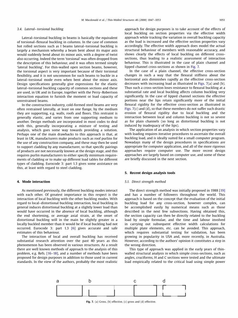
Fig. 7. (a) Gross, (b) effective,
approach for design purposes is to take account of the effects oflocal buckling on section properties via the effective widthapproach while tracking the variation in overall buckling capacityas the load is increased and the effective section properties varyaccordingly. The effective width approach does model the actualstructural behaviour of members with reasonable accuracy, andshows clearly the effects of local buckling on different cross-sections, thus leading to a realistic assessment of interactionbehaviour. This is illustrated in the case of plain channel andlipped channel cross-sections as shown in Fig. 7.
In the case of a plain channel, the effective cross-sectionchanges in such a way that the flexural stiffness about thehorizontal axis diminishes rapidly as the effective cross-sectiondecreases with increasing load as illustrated in Figs. 7(a) and (b).Thus such a cross-section loses resistance to flexural buckling at asubstantial rate and local buckling affects column buckling verysignificantly. In the case of lipped channel sections the effectiveportions near the lips retain significantly more of the initialflexural rigidity for the effective cross-section as illustrated inFigs. 7(c) and (d), so that these members do not suffer such drasticerosion of flexural rigidity due to local buckling and theinteraction between local and column buckling is not so severeas for plain channels (so long as distortional buckling is notinduced by inadequacy of the lips).
The application of an analysis in which section properties varywith loading requires iterative procedures to ascertain the overallbuckling load, and is ideally suited for a small computer program.Nowadays many of the design procedures in specifications areappropriate for computer application, and all of the more rigorousapproaches require computer use. The more recent designapproaches are largely based on computer use, and some of theseare briefly discussed in the next section.
5. Recent design analysis tools
5.1. Direct strength method
The direct strength method was initially proposed in 1988 [19]and has a number of followers throughout the world. Thisapproach is based on the concept that the evaluation of the initialbuckling load for any cross-section, however complex, canbe accomplished easily by numerical means such as thosedescribed in the next few subsections. Having obtained this,the section capacity can then be directly related to the bucklingload by simple formulae, and the time and labour involvedin carrying out subsequent effective width calculations formultiple plate elements, etc. can be avoided. This approach,which requires substantial testing for validation, has beengrowing in popularity in USA and, more recently, in Australia.However, according to the authors’ opinion it constitutes a step inthe wrong direction.
This type of approach was applied in the early years of thin-walled structural analysis in which simple cross-sections, such asangles, cruciforms, H and C sections were tested and the ultimateload empirically related to the critical load using simple power
(c) gross and (d) effective.

ARTICLE IN PRESS
M. Macdonald et al. / Thin-Walled Structures 46 (2008) 1047–10531052
laws based on the test results. This does produce simple estimatesof the load capacity of such members, but, as could be expected,the power laws were different for each particular section. Themethod does not really take adequate account of the differencescaused by cross-sectional geometry on post-buckling behaviour,and at best will produce results with a non-specific degree ofapproximation, which can only be determined on the basis oftests. In any case, just as it is relatively easy nowadays todetermine buckling loads using numerical methods, it is also easyto extend the analysis into the post-buckling range, i.e. go thewhole way by computer rather than stop after the first hurdle.This would seem to be the best approach.
5.2. Finite element method
The finite element method, in which a structure is discretisedinto a large number of small elements, has grown dramatically inpopularity and in simplicity of use over the last 40 years duelargely to the production of user friendly computer packages, andthis trend does not show any sign of abating. All largemanufacturing companies, and many smaller companies nowown and operate finite element packages, and it is likely that inthe not too distant future, finite element packages will take overthe design analysis of structures just as today computer packagesare widely used for structural layout, etc.
At the present time, for day-to-day design analysis, generalfinite element packages may be viewed to some extent assledgehammers too big to crack nuts with, and there are anumber of more specifically orientated numerical approachesused by researchers in this field which are particularly suited tothe analysis of cold-formed steel structural members.
Fig. 8 shows a deformed shape obtained from a finite elementmodel developed to investigate web crippling behaviour of cold-formed steel flexural members under both bending and webcrippling as described in detail in Ref. [20]. Half of the beam wasmodelled by considering the symmetry of the beam and loading.This model was developed by using the finite element packageANSYSs and its advanced finite element capabilities includingnonlinear material characteristics, geometrical nonlinearities andcontact elements which have all been employed in the analysis.
5.3. Finite strip method
The finite strip method, first introduced in the early 1970s, is aspecialised form of the finite element method particularly suitedto prismatic structures, for example, columns and beams. In thisapproach it is assumed that the deformation pattern of a structure
Fig. 8. Web crippling finite element model.
in one direction can be evaluated analytically and finite elementscan be replaced by strips, which extend the complete length of themember. This reduces the number of elements substantially, forexample, the numbers of strips required to accurately analyse a10 m long beam with five walls of developed width 0.5 m is about20 compared with perhaps 8000 elements. Thus the computationrequired is much less than for the parent finite element method,and the results can be presented and viewed in a more conciseform. Many of the finite strip programs available at the presenttime are suitable only for determination of the critical loads ofstructural members, and this may explain to some extent theinterest in the direct strength method. However, there are finitestrip programs, which can examine the post-buckling range, andthere is no reason why all such programs cannot be extended intothe post-buckling range.
Typical examples of finite strip output for the case of a simplysupported compressed top hat section are shown in graphicalform in Fig. 9. Fig. 9(a) shows the variation of buckling coefficientK (see Eq. (2)) related to the web width with variation in length ofthe member. Three different modes arise at different memberlengths, but at lengths greater than about 60 mm the distortionaland torsional–flexural modes are preceded by multi-wavelengthlocal buckling, and as a result the buckling coefficients shown forthese modes are not truly valid. The finite strip program used herehas the capability of post-buckling analysis, however, and this isillustrated in Fig. 9(b). Here, for member lengths greater than that
Fig. 9. Variation of buckling coefficient K with length L for a simply supported top
hat section.

ARTICLE IN PRESS
M. Macdonald et al. / Thin-Walled Structures 46 (2008) 1047–1053 1053
at which the first minimum local buckling coefficient is achieved,the interaction of local buckling on the longer wavelength modesis taken into account in determining the non-dimensionalbuckling coefficients related to buckling strain and buckling stressfor the higher modes. In this figure the garlanded curves for multi-wavelength buckling are omitted for clarity.
The finite strip method, particularly with post-bucklinganalysis capabilities, is a most useful analytical tool for cold-formed steel design.
5.4. Generalised beam theory
Generalised beam theory provides an alternative to finite stripanalysis, and so should be mentioned here. This approach,although initially derived at about the same time as the finitestrip method, took substantially longer to gain widespreadacknowledgement. Space requirements prevent any detaileddiscussion of this approach, and it may perhaps be sufficeto say that it is similar in applicability, although different inbackground, to the finite strip method. The authors are users andresearchers in the finite strip field, and so, are biased toward thatapproach.
6. Conclusions and recommendations
The complexity of design with regard to cold-formed steelmembers and structures has increased as their use has grown andthis trend will continue. Modern design specifications have takensubstantial steps in providing design analysis methodology, butthese are becoming increasingly complex, and can nowadaysinvolve greater labour than rigorous analysis using numericalmethods if computer packages are available. Some design codesactually specify the need to use second order analysis undercertain conditions. It would seem that perhaps this would be anopportune time to create a link between specifications andcomputer packages, with rigorous analysis using approvedpackages specified as complying with the design code. In 1984,at a conference in Glasgow [21], the last author suggested that‘‘one may well ask the question: should the next generation ofdesign codes, say in the early 1990s, be written as microcomputerpackages?’’ The projected time scale was perhaps too soon, but asimilar suggestion may be made today.
References
[1] American Iron and Steel Institute. Specification for the design of light gagesteel structural members. New York; 1946.
[2] British Standards Institution. Addendum no. 1 to BS 449:1959. Specificationfor the use of cold formed steel sections in building; 1961.
[3] Shearer-Smith W. Cold formed sections in structural practice with a proposeddesign specification. Struct Eng 1951;XXIX:165–78.
[4] British Standards Institution. BS 5950: part 5: code of practice for the designof cold formed steel member; 1987.
[5] ECCS-TWG7/1. European recommendations for the design of light gauge steelmembers; 1987.
[6] CEN ENV 1993-1.3. Eurocode3: design of steel structures–part 1.3: generalrules—supplementary rules for cold-formed thin gauge members andsheeting; 1996.
[7] ENV 1993-1-3. Eurocode 3: design of steel structures–part 1.4: generalrules–supplementary rules for stainless steel; 1996.
[8] Federation Europeene de la Manutention. Section X. Recommendations forthe design of steel pallet racking and shelving; 2000.
[9] Harvey JM. Studies on the interactions of plate components of structuralsections under selected load conditions. PhD thesis, University of Glasgow;1953.
[10] Hancock GJ. Distortional buckling of steel storage rack columns. ASCE J StructEng 1985;111(1):2770–83.
[11] Seah LK. Buckling behaviour of edge stiffeners in thin-walled sections. PhDthesis, University of Strathclyde, Glasgow; 1989.
[12] Hancock GJ. Design for distortional buckling of flexural members. Thin-Walled Struct 1997;20:3–12.
[13] Yang D, Hancock GJ. Developments in design for distortional buckling of thin-walled members. UK: ICTWS, University of Loughborough; 2004.
[14] Rhodes J, Nash D. An investigation of web crushing in thin-walled beams.Thin-Walled Struct 1998;32:207–30.
[15] Heiyantuduwa MA, Macdonald M, Rhodes J. Web crippling behaviour of thin-walled flexural members—an experimental investigation. In: The 6thinternational conference on steel and aluminium structures, Oxford, UK;2007.
[16] Graves Smith TR. The ultimate strength of locally buckled columns ofarbitrary length. In: Thin-walled steel construction symposium, UniversityCollege, Swansea; 1967.
[17] Koiter WT, Kuiken GDC. The interaction between local buckling and overallbuckling on the behaviour of built-up columns. Delft University of Technologyreport WTHD-32, 1971.
[18] Rhodes J, Harvey JM. Interaction behaviour of plain channel columns underconcentric or eccentric loading. In: The 2nd international colloquium on thestability of steel structures, Liege; 1977.
[19] Schafer BW, Pekoz T. Direct strength prediction of cold-formed steel membersusing numerical elastic buckling solutions. In: Shanmugam NE, et al., editors.Thin-walled structures. Amsterdam: Elsevier; 1998.
[20] Heiyantuduwa MA, Macdonald M, Rhodes J. Investigation of web cripplingbehaviour using non-linear finite element analysis. In: Proceedings of theSDSS 2006 international colloquium on stability and ductility of steelstructures, Lisbon; 2006. p. 713–20.
[21] Rhodes J. Some thoughts on future cold formed steel design rules. In: RhodesJ, Spence J, editors. Behaviour of thin-walled structures, Amsterdam: Elsevier;1984. Proceedings of the retiral conference for Prof. JM Harvey, University ofStrathclyde; 1984.