Recent Advances in PIM Technology I · Recent Advances in PIM Technology I ... The main advantages...
10
Science of Sintering, 40 (2008) 79-88 ________________________________________________________________________ _____________________________ *) Corresponding author: [email protected] doi: 10.2298/SOS0801077Z UDK 622.785:621:762 Recent Advances in PIM Technology I B. S. Zlatkov 1*) , E. Griesmayer 1 , H. Loibl 1 , O.S.Aleksić 2 , H. Danninger 3 , C. Gierl 3 , L.S.Lukić 4 1 FOTEC Forschungs- und Technologietransfer GmbH, Viktor Kaplan-Strasse 2, 2700 Winner Neustadt, Austria 2 Institute for Multidisciplinary Research- IMSI, Kneza Viseslava 1a, 11000 Belgrade, Serbia 3 Institute of Chemical Technologies and Analytics, Getreidemarkt 9/164, 1060 Wien, Austria 4 IRITEL AD Belgrade, Batajnicki put 23, 11080 Belgrade, Serbia Abstract: In this article the state of art of the PIM (Powder Injection Moulding) technology is given in brief. The main process flow diagram consisting of four steps: feedstock preparation, injection moulding (green samples forming), the debinding (binder removing) procedure and the sintering process was described. After that the materials for binders and additives for the surface active agents were mentioned in brief. The metal injection moulding (MIM) process was analysed in more detail: MIM- stainless steels, MIM-copper and MIM-aluminium as the most metals common in MIM metal parts production. After that our results of MIM stainless steel 316 L and MIM copper are given. The main powder characteristics, the shrinkage and density of the sintered samples were compared for isostatically pressed PM (powder metallurgy) samples and MIM formed samples. The SEM fractographs of MIM and PM samples are given for MIM green parts, debinded (brown) parts and sintered parts, and PM green parts and sintered parts. The results obtained were compared with literature data before they were applied in metal parts production. Keywords: Powder injection moulding (PIM) technology, Metal injection moulding (MIM), Ceramic injection moulding (CIM), Powder granulation, Feedstock, Debinding, Sintering. 1. Introduction Metal alloys or ceramic components with a high geometrical complexity, asymmetrical shapes and high precision needed (close tolerance), can be produced economically with a conventional injection moulding machine and granulates composed of a binder (plastic, wax), very fine ceramic or metal powders, and additives. This process is called PIM - powder injection moulding technology, and is regarded as fairly recent although the first injection moulding machines were built in the 1930's and used for ceramic powders. There are two other terms in use: MIM (metal injection moulding) and CIM (ceramic injection moulding). After the shaping process, which allows full 3D-geometries, the plastic (wax, thermo-plastics, silicone, etc.) is removed from the mould during the debinding process by catalytic, solvent (acetone, heptane, etc.) and thermal debinding. The metal or ceramic
Transcript of Recent Advances in PIM Technology I · Recent Advances in PIM Technology I ... The main advantages...

Science of Sintering, 40 (2008) 79-88 ________________________________________________________________________
_____________________________
*) Corresponding author: [email protected]
doi: 10.2298/SOS0801077Z UDK 622.785:621:762 Recent Advances in PIM Technology I B. S. Zlatkov1*) , E. Griesmayer1, H. Loibl1, O.S.Aleksić2, H. Danninger3, C. Gierl3, L.S.Lukić4 1 FOTEC Forschungs- und Technologietransfer GmbH, Viktor Kaplan-Strasse 2, 2700 Winner Neustadt, Austria 2 Institute for Multidisciplinary Research- IMSI, Kneza Viseslava 1a, 11000 Belgrade, Serbia 3 Institute of Chemical Technologies and Analytics, Getreidemarkt 9/164, 1060 Wien, Austria 4 IRITEL AD Belgrade, Batajnicki put 23, 11080 Belgrade, Serbia Abstract: In this article the state of art of the PIM (Powder Injection Moulding) technology is given in brief. The main process flow diagram consisting of four steps: feedstock preparation, injection moulding (green samples forming), the debinding (binder removing) procedure and the sintering process was described. After that the materials for binders and additives for the surface active agents were mentioned in brief. The metal injection moulding (MIM) process was analysed in more detail: MIM- stainless steels, MIM-copper and MIM-aluminium as the most metals common in MIM metal parts production. After that our results of MIM stainless steel 316 L and MIM copper are given. The main powder characteristics, the shrinkage and density of the sintered samples were compared for isostatically pressed PM (powder metallurgy) samples and MIM formed samples. The SEM fractographs of MIM and PM samples are given for MIM green parts, debinded (brown) parts and sintered parts, and PM green parts and sintered parts. The results obtained were compared with literature data before they were applied in metal parts production. Keywords: Powder injection moulding (PIM) technology, Metal injection moulding (MIM), Ceramic injection moulding (CIM), Powder granulation, Feedstock, Debinding, Sintering.
1. Introduction
Metal alloys or ceramic components with a high geometrical complexity,
asymmetrical shapes and high precision needed (close tolerance), can be produced economically with a conventional injection moulding machine and granulates composed of a binder (plastic, wax), very fine ceramic or metal powders, and additives. This process is called PIM - powder injection moulding technology, and is regarded as fairly recent although the first injection moulding machines were built in the 1930's and used for ceramic powders. There are two other terms in use: MIM (metal injection moulding) and CIM (ceramic injection moulding). After the shaping process, which allows full 3D-geometries, the plastic (wax, thermo-plastics, silicone, etc.) is removed from the mould during the debinding process by catalytic, solvent (acetone, heptane, etc.) and thermal debinding. The metal or ceramic

B.S.Zlatkov et al. /Science of Sintering, 40 (2008) 79-88 ___________________________________________________________________________
80
component is then sintered to high density in the same way as classically pressed components, but at optimal conditions for PIM samples. A flow diagram of the PIM technology is given in Fig. 1. In comparison to conventional production methods this technology requires considerably less finishing work, but requires a higher planned number of units due to the high costs of the injection moulding tool and the feedstock. However, many complex shapes can not be economically produced without the PIM technology.
The actual shaping process consists of the following steps: clamping, injection, dwelling, cooling, mould opening, ejecting. Clamping is to hold together two halves of the mould under pressure during injection and cooling. Injection is to force a melted plastic together with powder into the mould cavity by a piston or a screw. Granules are loaded into a hopper before the injection, they fall into a hot cylinder to be melted and are then moved with endless screw and transported through the sprue to the mould. The dwelling step is a pause in the injection process where the mould is still kept under pressure to ensure that all of the mould cavities are filled. The cooling step is defined by the time for the melted phase to cool and solidify within the mould. The opening step of the mould occurs when the clamping unit is opened and the mould separates into two halves. An ejecting rod and plate eject the finished piece from the mould. The unused sprues and runners can be recycled to be used again in future moulds.
Fig. 1 Flow diagram of PIM technology.
The main advantages of PIM compared to other previous techniques such as machining or investment casting are: higher complexity of geometrical shapes of products, high production rates, repeatable high tolerances, wide range of available materials, low labour costs, minimal scrap losses, minor need to finish parts after moulding. The disadvantages are: high cost of powder, equipment investment, possible high running costs, and design of the parts in consideration of the moulding.
Ideal starting powders should have the following characteristics [1]: Tailored particle size distribution, for high packing density and low cost (mixture of

B.S.Zlatkov et al./Science of Sintering, 40 (2008) 79-88 ___________________________________________________________________________
81
lower cost large particles and higher cost small particles) No agglomeration Predominantly spherical (or at least equiaxed) particle shape Smooth surfaces for better flow of the feedstock Sufficient inter-particle adhesion to avoid distortion after binder removal Small mean particle size for rapid sintering, <20 µm Dense particles free of internal voids Minimized explosion and toxic hazards Clean particle surface for predictable interaction with the binder
The choice of powder is restricted to its availability, but growing demand has
stimulated a major effort by powder manufacturers to produce powders that meet the special requirements of PIM.
Binders used most often are: PP-polypropylene, POM-polyoxymethylene, PE-polyethylene, PS-polystyrene, PVC-polyvinyl chloride, PW-paraffin, wax, PEC-polyethylene carbonate, PEG-polyethylene glycol and MW-microcrystalline wax. A combination of two binders (one as the main and the other as a secondary) gives the best results: the main binder is debinded almost completely and the residual one (“backbone”) gives strength to PIM shaped samples after debinding.
Additives known as surface active agents (to lower viscosity and improve wetting) used most often are: ammonium polyacrylate, dibutyl phthalate, dimethyl phthalate, diglyceride stearate and oleate, fish oil, glyceryl mono stearate, isopropyl tri (dioctyl) phosphate titanate, linseed oil, lithium stearate, monoglyceride, naphthalene sulfonate formaldehyde, octyl acid phosphate, olefin sulfonate, phosphate ester, polyoxyethylene, sorbitan fattyacid ester, stearic acid, zinc stearate etc. 2. MIM (Metal Injection Moulding)
Metal injection moulding (MIM) uses metal powders. The list of metals that have been used in metal injection moulding includes: stainless steels, high speed steels, copper base alloys, nickel and cobalt base superalloys, titanium, intermetallics, magnetic alloys, refractory metals and hard metals etc. The metal powder is mixed with a polymer-binder and moulded using an injection moulding machine. The polymer-binder is removed during debinding, and then the part is sintered while the shape is maintained. The features of metal injection moulding are: high and uniform density, excellent surface finish, excellent strength and tremendous shape complexity including undercuts, threads, and thickness variations. In comparison to the classical techniques of metal parts processing and finishing [2], MIM has several advantages regarding to complexity, material range and part size (see Tab. I) [2]. Tab. I. Simplified comparison of metal part processing and finishing techniques. Attribute Metal injection
moulding (MIM) Press and
sintering (P/S) Centrifugal investment
casting (CIC) Machining
Density 95-100 % 85-95 % 95-99 % 100 % Strength 95 to 100 % 70-90 % 98 % 100 % Surface finish 0.4 to 0.8 µm <2 µm 3 µm 0.4 to 2 µm Wall thickness 0.1 to 10 mm ≥2 mm ≥5 mm ≥2 mm Complexity high medium medium high Suitable production volume
medium to high medium to high low to medium low
Size range 0.003 g to 250 g 0.1 g to 10 kg ≥1 g ≥0.1 g

B.S.Zlatkov et al. /Science of Sintering, 40 (2008) 79-88 ___________________________________________________________________________
82
2.1. MIM Steels
One of the most significant groups of MIM products are ferrous parts (stainless steel, low alloy steel, tool steel) since they are the most widely applied. The stainless steels (17-4PH, 316L, 410L, 420L, 440C) are often applied in medicine, electronics, tools, sporting goods, aerospace and consumer products because of their good properties, such as: strength, heat and corrosion resistance, elongation, hardness, wear resistance, magnetic response, processability. The low alloy steels (2200, 2700, 4605, 8620, 4140, 5210, etc.) are applied in tools, bearings, races, and consumer goods because of their specific good properties such as: being magnetic material, case hardenable, heat treatable. Tool steels (M2, M4, M42, H13, T15) are applied in wood and metal cutting tools because of their properties such as: low cost, high cutting speed, hardenability, processability. The steels most often presented in the literature are stainless steels 316L and 17-4PH. Tab. II. Chemical composition of 316L stainless steel [%wt] as sintered [11].
C Si Mn P S Cr Ni Mo Fe 0.026 0.36 1.44 0.01 0.041 16.11 9.97 1.92 balance
The problems investigated could be summarized as: microstructural evolution [3], mechanical properties [4], analysis of the rheological behaviour and stability [5], feedstock mixing and characterization [6], thermal debinding [7], improvements in sintered density and dimensional stability [8], low-pressure injection moulding [9], sintering activation energy [10], etc.
Fig. 2 Microstructure of PIM shaped µ-pin array of 316L stainless steel sintered at 1300 °C. Pin Ø100 µm × height 200 µm [12].
For the example of stainless steel 316L, the initial particle size is 5-22 microns, sintering temperatures are 1250-1350 °C and the residual porosity is less than 2 %. The chemical composition is given in Tab. II [11]. The physical and mechanical properties of 316L with two different compositions of binder systems, A and B, are given in Tab. III [11].

B.S.Zlatkov et al./Science of Sintering, 40 (2008) 79-88 ___________________________________________________________________________
83
Tab. III. Physical and mechanical properties of sintered 316L [11].
2.2. MIM Copper
Copper is often used for applications that require higher thermal conductivities than other metals can provide. Copper powders are commercially available in a wide range of particle shapes and sizes and can be produced by several processes including oxide reduction (OR), water atomization (WA), gas atomization (GA), and jet milling (JM). Paraffin wax or similar with suitable additives (see Tab. 4) is used most commonly as binder [13-15]. The copper-to-binder ratio in the typical feedstock is 95 %wt : 5 %wt, that means 66.2 %wt of copper loading. Tab. IV. Binder composition.
Debinding is performed in two steps: debinding in suitable solvent and thermal
debinding (350-600 °C). The sintering process for pure copper takes place at 980-1050 °C. The sintered densities range at 93-96 % independent of the production method or particle size. The microstructure of the pure powder, the debinded specimen, and the sintered sample are given in Fig. 3 (a, b, c) respectively [13].
(a) (b) (c)
Fig. 3 SEM micrographs of the pure copper powder (a), the debinded specimen at 500 °C (b) and fracture surface after sintering at 1050 °C (c). The sintered density reaches 8.18 [g/cm3] and (91.6 %rel), respectively.
Thermal conductivities range from 280 W/mK for two of the water-atomised powders, to 385 W/mK for the jet-milled powder. Porosity and traces of metallic impurities, especially iron, are the primary factors that control the thermal conductivity of sintered copper. Tungsten with 15-20 weight percent copper (W-15Cu and W-20Cu) is a common heat sink composition. Molybdenum with 18 %we copper (Mo-18Cu) has a lower thermal conductivity but its lower density makes it attractive for applications where weight is
Properties System A System B Density [g/cm3] 7.845 7.853 Hardness [HV] 162.5 160.1 Shrinkage [%] 14.17 13.88 Strength [MPa] 511.87 511.23 Elongation [%] 21.74 21.63
Binder constituents Density [g/cm3] Melting point T [°C] Weight [%]
Paraffin wax 0.89-0.91 60-65 65 Polyethylene 0.954-0.957 130 30 Stearic acid 0.96 67-69 5

B.S.Zlatkov et al. /Science of Sintering, 40 (2008) 79-88 ___________________________________________________________________________
84
important. Both have much lower thermal expansion factors than pure copper, and are suitable for use as heat sinks for chips in electronics. The most common heat sinks, pure copper MIM shaped and sintered, are given in Fig. 4 [16, 17].
Fig. 4 PIM shaped copper heat sinks designed for cooling in electronics.
2.3. MIM Aluminium
Aluminium has excellent thermal conductivity, low weight, low melting temperature, and low hardness. Aluminium powders of various sizes are commercially available, but the oxide layer that forms on the particles inhibits formation of sintering contacts and densification. For this reason, special sintering procedures and atmospheres are required to produce parts with sufficient strength and low porosity. Typical MIM density obtained with aluminium are 2.5 g/cm3 while die-cast or extruded aluminium reaches 2.7 g/cm3. In MIM aluminium heat sinks, thermal conductivity reaches 170-180 mW/K. Higher purity of metal injection moulded aluminium results in higher thermal conductivity. The binder composition contains polyethylene, paraffin and stearic acid. Debinding has two steps, debinding in hexane and subsequently thermal debinding at 250-500 °C.
Fig. 5 Examples of heat sink geometries produced with aluminium MIM. Heat sinks up to 50×50×50 mm³ are most amenable to processing by MIM.
The use of MIM pure aluminium encounters very different problems such as grain
oxidation and grain growth. The injection of aluminium powder alloys Al-Ti-B are also of interest for refinement of the molten Al [17], MIM of Ti-Al intermetallics is also analysed [18]. Recent investigations show: fast melting of Al-alloys by laser to avoid skin oxidation [19], orientation of short fibres in powder injection moulded aluminium matrix composites [20], shrinkage during removal of organic vehicle from injection moulded aluminium bodies [21] etc. In practice MIM shaped aluminium heat sinks of larger size (50x50x50 mm3) were developed [22] with tolerances of ±50 µm (Fig. 5).

B.S.Zlatkov et al./Science of Sintering, 40 (2008) 79-88 ___________________________________________________________________________
85
3. Experimental and Results 3.1. MIM Stainless Steel 316L
Selected SEM micrographs of PIM and PM stainless steel 316L are shown in Fig. 6. The microstructure of PIM green samples made by melt feedstock injected into the mould is shown in picture (a), powder particles around 22 µm can be seen together with binder. After the debinding process, when most of the binder was removed by solvent, the same particles can be seen very clearly, as shown in picture (b). Sintered microstructure of PIM samples is achieved by sintering at 1300 °C/1 h in hydrogen. The microstructure of pressed PM green samples made of around 7 times larger particles (150 µm) at about 7 times higher pressure (500-800 MPa) is shown in picture (d). The fracture surface of sintered PM samples achieved at the same sintering profile as for PIM samples is shown in figure (e), and lock shield PIM sintered products of 316L is shown in picture (f): green part left and sintered part right. The PIM shaped lock shield was our first PIM product . The main properties of sintered PIM and PM samples are given in table 5 as follows.
(a) (b) (c)
(d) (e) (f)
Fig. 6 SEM fractographs of MIM and PM 316 L samples magnified ×1000:Green MIM (a), debinded (b) sintered (c), green PM (d), sintered PM (e), lock shields shaped by MIM (green part-left, sintered part-right) (f).
Tab. V. MIM and PM samples sintered in hydrogen.
Material Particle size [µm]
Injection pressure (MIM)
Pressure (PM) [MPa]
Tsint [°C/1h]
Density [g/cm3]
Shrinkage [%]
MIM 316L dB 95 ≤22 80 1300 7.41 11.5 MIM 316L dB 95 ≤22 120 1300 7.44 11.7 PM 316L dB 100 ≤150 500 1300 6.07 1.87 PM 316L dB 100 ≤ 150 800 1300 7.08 1.27
50µm
20µm
50µm 50µm
50µm

B.S.Zlatkov et al. /Science of Sintering, 40 (2008) 79-88 ___________________________________________________________________________
86
The MIM stainless steel 316L (SEM Fig. 6 and Tab. V) are similar to the results of 316L given in Tab. 3. Parallel to MIM samples, isostatically pressed and sintered (PM) samples were analysed. The PIM results presented in Tab. V are superior to the PM results in density (7.44 vs. 7.08 g/cm3) and in material hardness (caused by the increase of density). 3.2. MIM Copper
Selected SEM micrographs of PIM and PM copper samples are shown in Fig. 7 The microstructure of PIM Cu green samples made by melt feedstock injected into the mould is shown in figure 7 (a); particles of Cu round 22 µm can be seen together with the binder. After the debinding process, when most of the binder was removed by a solvent the same particles can be seen very clearly as shown in figure 7 (b). The sintered microstructure of the PIM Cu sample is achieved by sintering at 1000 °C/1h in hydrogen. The microstructure of pressed PM green Cu samples made of round 7 times larger particles (150 µm) at round 3-4 times higher pressure (200-500 MPa), is shown in figure 7 (d). The fracture surface of sintered PM Cu samples achieved at the same sintering profile as for PIM samples is shown in figure 7 (e). Our large heat sink figure 7 (f), shaped of copper is more complex than aluminium PIM shaped heat sink shown in Fig.s 4 and 5. This heat sink shape with small and long tubes used instead of pins is patented by Fotec, Wiener Neustadt, Austria, and is considered to be a superior product with the most advanced shape developed to date. The base area is 50×50 mm², the height is 30 mm and there are 96 pins. The main properties of Cu-based PIM and PM samples are given in Tab. VI.
(a) (b) (c)
(d) (e) (f)
Fig. 7 SEM fractographs of MIM and PM Cu samples magnified ×1000: MIM green part (a), MIM debinded (brown) part (b), MIM sintered part (c), green PM part (d), sintered PM part (e), Cu heat sink shaped by MIM (f).
50µm 50µm 50µm
50µm 50µm
B.S.Zlatkov et al./Science of Sintering, 40 (2008) 79-88 ___________________________________________________________________________
87
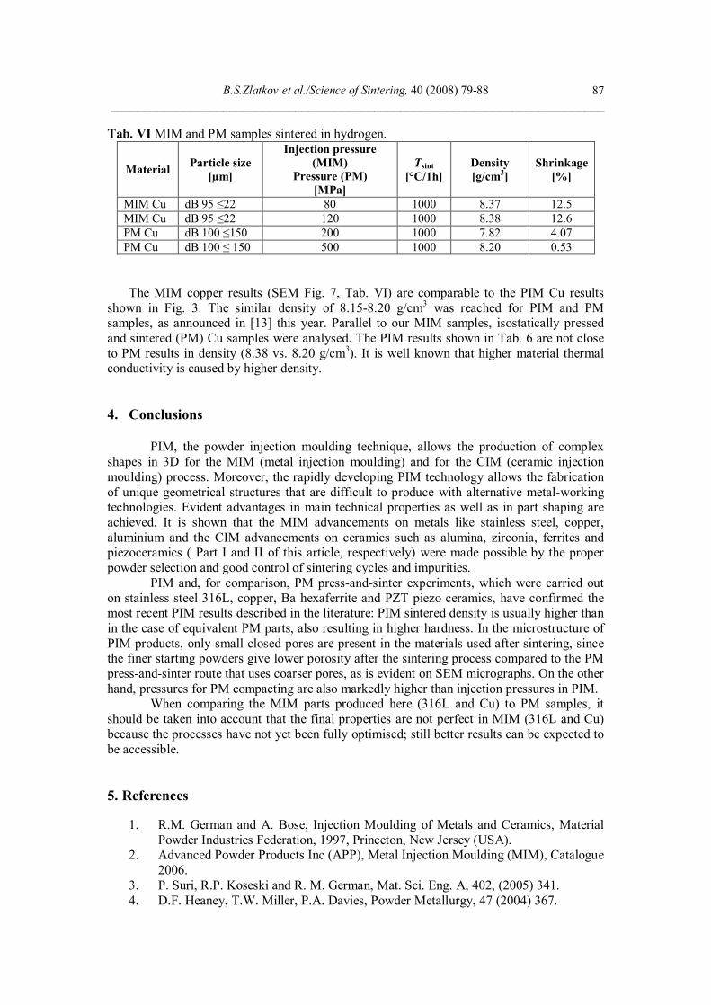
Tab. VI MIM and PM samples sintered in hydrogen.
Material Particle size [µm]
Injection pressure (MIM)
Pressure (PM) [MPa]
Tsint [°C/1h]
Density [g/cm3]
Shrinkage [%]
MIM Cu dB 95 ≤22 80 1000 8.37 12.5 MIM Cu dB 95 ≤22 120 1000 8.38 12.6 PM Cu dB 100 ≤150 200 1000 7.82 4.07 PM Cu dB 100 ≤ 150 500 1000 8.20 0.53
The MIM copper results (SEM Fig. 7, Tab. VI) are comparable to the PIM Cu results shown in Fig. 3. The similar density of 8.15-8.20 g/cm3 was reached for PIM and PM samples, as announced in [13] this year. Parallel to our MIM samples, isostatically pressed and sintered (PM) Cu samples were analysed. The PIM results shown in Tab. 6 are not close to PM results in density (8.38 vs. 8.20 g/cm3). It is well known that higher material thermal conductivity is caused by higher density. 4. Conclusions
PIM, the powder injection moulding technique, allows the production of complex
shapes in 3D for the MIM (metal injection moulding) and for the CIM (ceramic injection moulding) process. Moreover, the rapidly developing PIM technology allows the fabrication of unique geometrical structures that are difficult to produce with alternative metal-working technologies. Evident advantages in main technical properties as well as in part shaping are achieved. It is shown that the MIM advancements on metals like stainless steel, copper, aluminium and the CIM advancements on ceramics such as alumina, zirconia, ferrites and piezoceramics ( Part I and II of this article, respectively) were made possible by the proper powder selection and good control of sintering cycles and impurities.
PIM and, for comparison, PM press-and-sinter experiments, which were carried out on stainless steel 316L, copper, Ba hexaferrite and PZT piezo ceramics, have confirmed the most recent PIM results described in the literature: PIM sintered density is usually higher than in the case of equivalent PM parts, also resulting in higher hardness. In the microstructure of PIM products, only small closed pores are present in the materials used after sintering, since the finer starting powders give lower porosity after the sintering process compared to the PM press-and-sinter route that uses coarser pores, as is evident on SEM micrographs. On the other hand, pressures for PM compacting are also markedly higher than injection pressures in PIM.
When comparing the MIM parts produced here (316L and Cu) to PM samples, it should be taken into account that the final properties are not perfect in MIM (316L and Cu) because the processes have not yet been fully optimised; still better results can be expected to be accessible. 5. References
1. R.M. German and A. Bose, Injection Moulding of Metals and Ceramics, Material Powder Industries Federation, 1997, Princeton, New Jersey (USA).
2. Advanced Powder Products Inc (APP), Metal Injection Moulding (MIM), Catalogue 2006.
3. P. Suri, R.P. Koseski and R. M. German, Mat. Sci. Eng. A, 402, (2005) 341. 4. D.F. Heaney, T.W. Miller, P.A. Davies, Powder Metallurgy, 47 (2004) 367.

B.S.Zlatkov et al. /Science of Sintering, 40 (2008) 79-88 ___________________________________________________________________________
88
5. M. Khakbiz, A. Simchi R. Bagheri, Mat. Sci. Eng. A, 407 (2005) 105. 6. L. Liu, N.H. Loh, B.Y. Tay, S.B. Tor, Y. Murakoshi R. Maeda, Materials
Characterization, 54 (2005) 230. 7. Y. Li, S. Liu, X. Qu, B. Huang, Journal of Materials Processing Technology, 137
(2003) 65. 8. G.J. Shu, K.S. Hwang, Y.T. Pan, Acta Materialia, 54 (2006) 1335. 9. M. Rei, E. C. Milke, R. M. Gomes, L. Schaeffer, J. P. Souza, Materials Letters, 52
(2002) 3650. 10. Z. Y. Liu, N. H. Loh, K. A. Khor, S. B. Tor, Scripta Materialia, 44 (2001) 1131. 11. G. Fu, N.H. Loh, S.B. Tor, B.Y. Tay, Y. Marakoshi, R. Maedea, Applied Physics A,
81 (2005) 495. 12. M.A. Omar, R. Ibrahim, M.I. Sidik, M. Mustapha, M. Mohamad, Journal of
Materials Processing Technology, 140 (2003) 397. 13. C.K. Kim, C.Y. Son, D.J. Ha, T.S. Yoon, S. Lee, N.J. Kim, Mat. Sci. Eng. A 476
(2008) 69. 14. L. Moballegh, J. Morshedian, M. Esfandeh, Materials Letters, 59 (2005) 2832. 15. C.T. Huang, K.S. Hwang, Powder Metallurgy, 39 (1996) 119. 16. Advanced Materials Technologies-AMT, Non-ferrous (nfMIM), Catalogue 2006. 17. C. Limmaneevichitr, W. Eidhed, Mat. Sci. Eng. A, 355 (2003) 174. 18. R. Gerling, E. Aust, W. Limberg, M. Pfuff, F.P. Schimansky, Mat. Sci. Eng. A, 423
(2006) 262. 19. J.A. Vreeling, V. Ocelik, Y.T. Pei, D.T.L. Van Agterveld, J.Th.M. De Hosson, Acta
Materialia, 48 (2000) 4225. 20. F. Ahmad, Journal of Materials Processing Technology, 169 (2005) 263. 21. M.J. Bevis et al., Powder Metallurgy, 35 (1992) 113. 22. J.L. Johnson, L.K. Tan, Electronics Cooling, 10 (2004) A2.
Садржај: У првом делу овог рада укратко је описана ПИМ технологија (бризгање композита-праха са растопљеним везивом). Описан је главни дијаграм тока процеса састављен је од четири корака : припрема композита, бризгање растопљеног композита (добијање зелених узорака), одстрањивање везива и процес синтеровања.После тога кратко су анализирани материјали за везива и материјали за квашење површине честице. Процес бризгања метала (МИМ) је анализиран много детаљније : МИМ нердјајући челици, МИМ бакар и МИМ алуминијум као најчешћи метали у приизводњи металних делова. После тога дати су наши резултати на МИМ 316 нердјајућем челику и МИМ бакру. Главне карактеристике праха, скупљање и густина синтерованих узорака су упоредјење за изостатички пресоване ПМ (металургија праха) и МИМ (бризгане) узорке. СЕМ фотографије за МИМ и ПМ узорке су дате за МИМ: несинтероване (зелене), са одстрањеним везивом (браон) и синтероване узорке, а затим за ПМ несинтероване (зелене) и синтероване узорке. Добијени резултати су упоредјени са литературним пре него сто су коришћени у производњи металних делова. Кључне речи: Технологија бризгања композита-праха са растопљеним везивом (ПИМ), бризгање металних прахова (МИМ), бризгање керамичких прахова (ЦИМ), гранулација праха, композит , одстрањивање везива, синтеровање.