
Receiver Design - ntuemc.twntuemc.tw/upload/file/201102212236275c060.pdf · Prof. Tzong-Lin Wu EMC...
49
Prof. Tzong-Lin Wu EMC Laboratory Department of Electrical Engineering National Taiwan University 2011/2/21 Receiver Design 1 MW & RF Design / Prof. T. -L. Wu
-
Upload
hoangnguyet -
Category
Documents
-
view
224 -
download
1
Transcript of Receiver Design - ntuemc.twntuemc.tw/upload/file/201102212236275c060.pdf · Prof. Tzong-Lin Wu EMC...

Prof. Tzong-Lin Wu
EMC Laboratory
Department of Electrical Engineering
National Taiwan University
2011/2/21
Receiver Design
1MW & RF Design / Prof. T. -L. Wu
2011/2/21
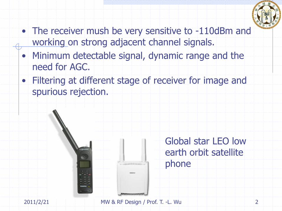
• The receiver mush be very sensitive to -110dBm and working on strong adjacent channel signals.
• Minimum detectable signal, dynamic range and the need for AGC.
• Filtering at different stage of receiver for image and spurious rejection.
Global star LEO low earth orbit satellite phone
2MW & RF Design / Prof. T. -L. Wu
2011/2/21
10.1 Receiver Architecture
Receiver requirements
• High gain ~100dB
• Selectivity
• Down-conversion
• Detection of received signal
• Isolation from the transmitter to avoid saturation of receiver.
3MW & RF Design / Prof. T. -L. Wu

2011/2/21 MW & RF Design / Prof. T. -L. Wu 4
Because the typical signal power level from the receive antenna may be as low as -100 to - 120 dBm, the receiver may be required to provide gain as high as 100 to 120 dB.
This much gain should be spread over the RF, IF, and baseband stages to avoid instabilities and possible oscillation;
It is generally good practice to avoid more than about 50-60 dB of gain at any one frequency band.
Selectivity can be obtained by using a narrow bandpass filter at the RF stage of the receiver, but the bandwidth and cutoff requirements for such a filter are usually impractical to realize at RF frequencies.
It is more effective to achieve selectivity by downconverting a relatively wide RF bandwidth around the desired signal, and using a sharpcutoff bandpass filter at the IF stage to select only the desired frequency band.
Full-duplex communications systems usually use separate frequency bands for transmit and receive, thus avoiding the difficult (but not impossible) problem of isolating incoming and outgoing radiation at the same frequency.
In addition, it is often preferred to use a single antenna for both transmit and receive. In this case it is necessary to use a duplexing filter to provide isolation between the transmitter and receiver, while still providing a signal path with the antenna
2011/2/21
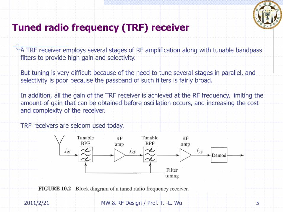
Tuned radio frequency (TRF) receiver
5MW & RF Design / Prof. T. -L. Wu
A TRF receiver employs several stages of RF amplification along with tunable bandpassfilters to provide high gain and selectivity.
But tuning is very difficult because of the need to tune several stages in parallel, and selectivity is poor because the passband of such filters is fairly broad.
In addition, all the gain of the TRF receiver is achieved at the RF frequency, limiting the amount of gain that can be obtained before oscillation occurs, and increasing the cost and complexity of the receiver.
TRF receivers are seldom used today.
2011/2/21
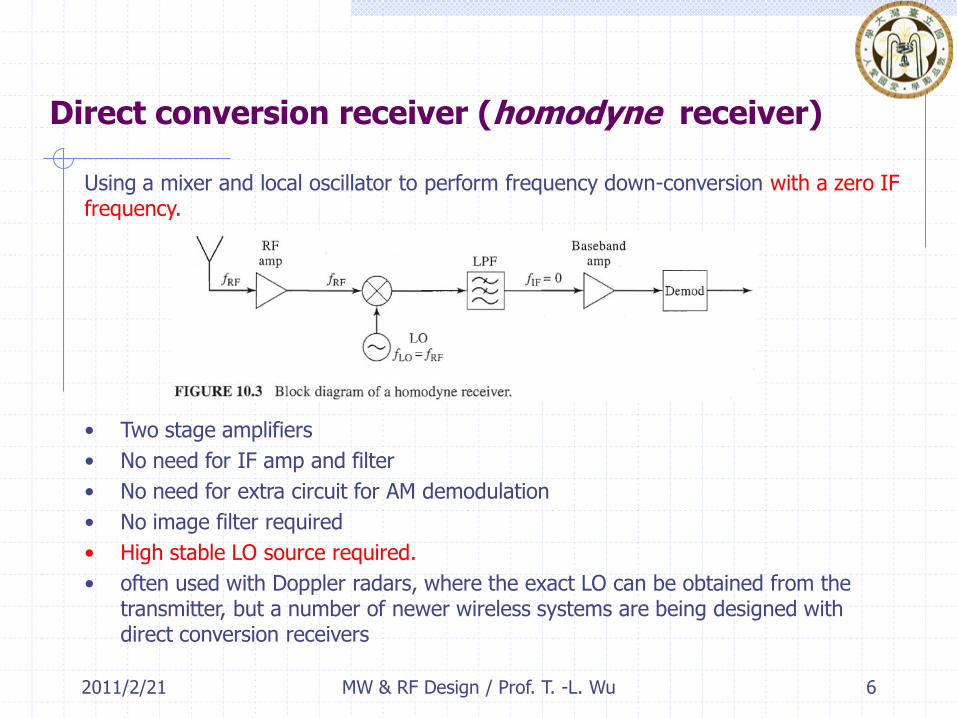
Direct conversion receiver (homodyne receiver)
• Two stage amplifiers
• No need for IF amp and filter
• No need for extra circuit for AM demodulation
• No image filter required
• High stable LO source required.
• often used with Doppler radars, where the exact LO can be obtained from the transmitter, but a number of newer wireless systems are being designed with direct conversion receivers
6MW & RF Design / Prof. T. -L. Wu
Using a mixer and local oscillator to perform frequency down-conversion with a zero IF frequency.
2011/2/21
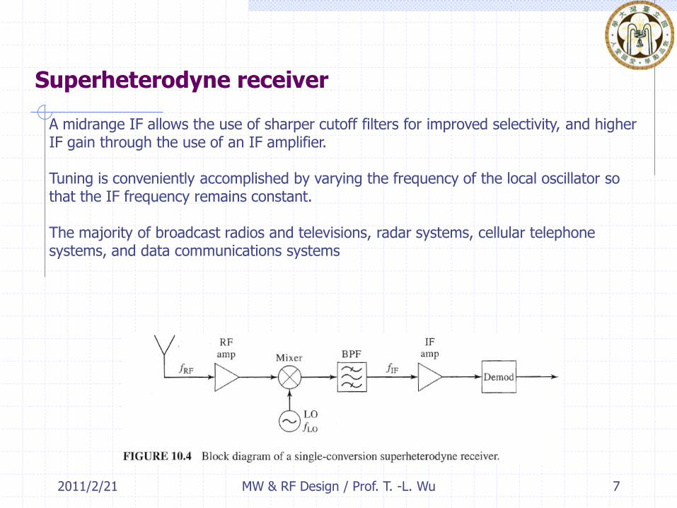
Superheterodyne receiver
7MW & RF Design / Prof. T. -L. Wu
A midrange IF allows the use of sharper cutoff filters for improved selectivity, and higher IF gain through the use of an IF amplifier.
Tuning is conveniently accomplished by varying the frequency of the local oscillator so that the IF frequency remains constant.
The majority of broadcast radios and televisions, radar systems, cellular telephone systems, and data communications systems
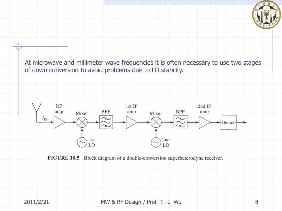
2011/2/21 MW & RF Design / Prof. T. -L. Wu 8
At microwave and millimeter wave frequencies it is often necessary to use two stagesof down conversion to avoid problems due to LO stability.
2011/2/21
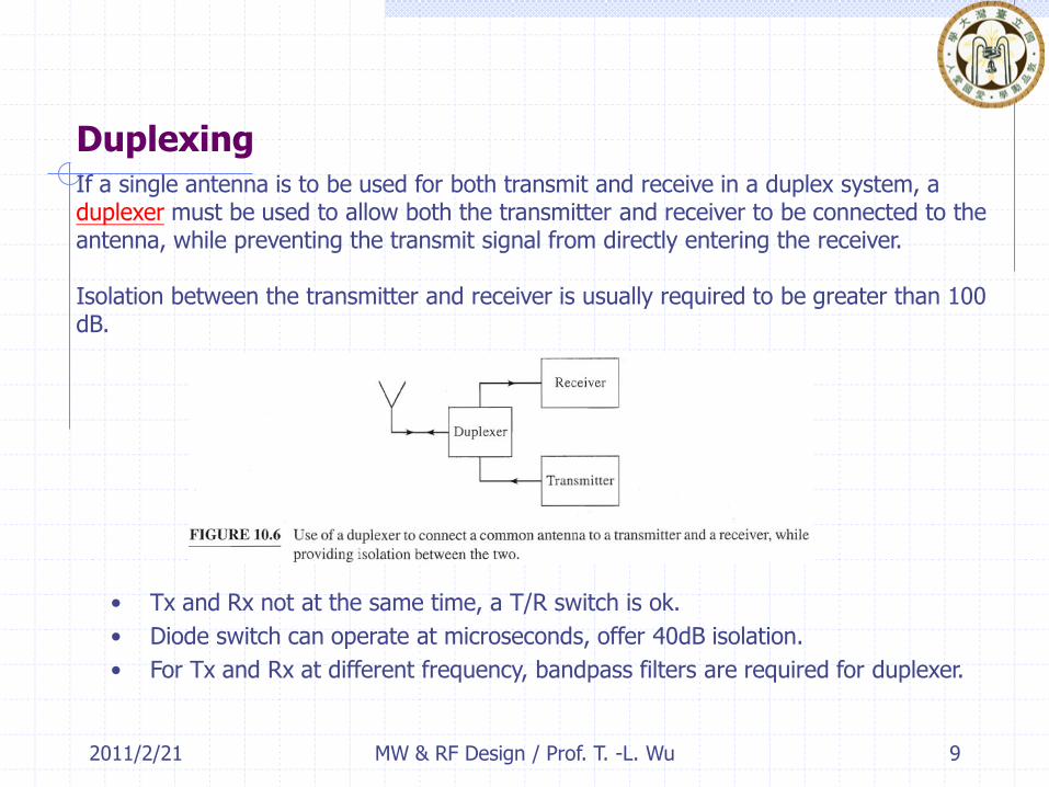
Duplexing
• Tx and Rx not at the same time, a T/R switch is ok.
• Diode switch can operate at microseconds, offer 40dB isolation.
• For Tx and Rx at different frequency, bandpass filters are required for duplexer.
9MW & RF Design / Prof. T. -L. Wu
If a single antenna is to be used for both transmit and receive in a duplex system, aduplexer must be used to allow both the transmitter and receiver to be connected to theantenna, while preventing the transmit signal from directly entering the receiver.
Isolation between the transmitter and receiver is usually required to be greater than 100 dB.

2011/2/21 10MW & RF Design / Prof. T. -L. Wu
Full-duplex systems usually use separate transmit and receive frequency bands withbandpass filters to provide duplexing.
They can also provide some preselective filtering on receive, and attenuate spurious out-of-band signals from the transmitter. Duplexing filters often have insertion losses on the order of 1-3 dB, however, which degrades the noise figure of the receiver.
A related component is a diplexer, a term generally used to refer to a device that combines two or more frequency components into a single channel.
Since a duplexing filter used with different transmit and receive frequency bands fits this definition, it is sometimes referred to as a diplexing filter.

2011/2/21 11MW & RF Design / Prof. T. -L. Wu

2011/2/21 12MW & RF Design / Prof. T. -L. Wu

2011/2/21
10.2 Dynamic Range
Reliable communication requires a receive signal power at or above a certain minimum level, which we call the minimum detectable signal (MDS).
Minimum detectable signal (MDS) determines the minimum SNR at the demodulator for a given system noise power.
Minimum detectable signal (MDS)
13MW & RF Design / Prof. T. -L. Wu

2011/2/21
SINAD: signal-plus-noise-plus-distortion to noise-plus-distortion ratio.
The ratio of (a) total received power, i.e., the received signal-plus-noise-plus-distortion power to (b) the received noise-plus-distortion power.
14MW & RF Design / Prof. T. -L. Wu
Knowing the minimum SNR or SINAD and the noise characteristics of the receiving system allows us to calculate the minimum detectable signal power.

Minimum Detectable Power
2011/2/21 MW & RF Design / Prof. T. -L. Wu 15
the output signal power
Receiver Noise temperature
total output noise power
where B is the bandwidth of the receiver (usually set by the IF bandpass filter).
2011/2/21 16MW & RF Design / Prof. T. -L. Wu
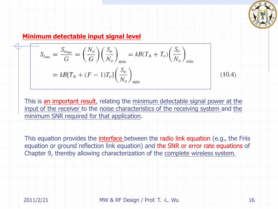
Minimum detectable input signal level
This is an important result, relating the minimum detectable signal power at the input of the receiver to the noise characteristics of the receiving system and the minimum SNR required for that application.
This equation provides the interface between the radio link equation (e.g., the Friisequation or ground reflection link equation) and the SNR or error rate equations of Chapter 9, thereby allowing characterization of the complete wireless system.
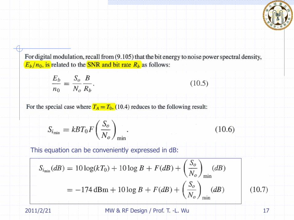
2011/2/21 MW & RF Design / Prof. T. -L. Wu 17
This equation can be conveniently expressed in dB:
2011/2/21 MW & RF Design / Prof. T. -L. Wu 18
Although (10.6 and10.7) are sometimes used in place of (10.4), it is important to realize that (10.6 and 0.7) are only valid when the antenna temperature is 290 K, this situation is seldom true in practice.
In either case, note that the minimum detectable signal level does not depend on the gain of the receiver, since both signal and noise are increased equally.
Two important points:

2011/2/21 19MW & RF Design / Prof. T. -L. Wu

2011/2/21 20MW & RF Design / Prof. T. -L. Wu
2011/2/21
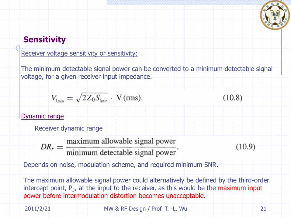
Sensitivity
Receiver voltage sensitivity or sensitivity:
The minimum detectable signal power can be converted to a minimum detectable signalvoltage, for a given receiver input impedance.
Dynamic range
Receiver dynamic range
Depends on noise, modulation scheme, and required minimum SNR.
The maximum allowable signal power could alternatively be defined by the third-order intercept point, P3, at the input to the receiver, as this would be the maximum input power before intermodulation distortion becomes unacceptable.
21MW & RF Design / Prof. T. -L. Wu

2011/2/21 22MW & RF Design / Prof. T. -L. Wu

2011/2/21 23MW & RF Design / Prof. T. -L. Wu

2011/2/21 MW & RF Design / Prof. T. -L. Wu 24
The above examples show the need for about 80-100 dB of receiver gain to raise theminimum detectable signal to a usable level of approximately 10 mW (about 1 V peak at 50 ohm).
Most of the gain occurring at the IF stage because
Amplifiers and other components are generally cheaper at lower frequencies.
High input signal levels may exceed the 1 dB compression point (P1),or the third-order intercept point (P3), of the front-end components if the gain of the early stages is too high.
Moderate level of gain at the RF stage sets a good noise figure for the receiver system.
Automatic gain control

2011/2/21 MW & RF Design / Prof. T. -L. Wu 25
Dynamic range at the output of the receiver is much smaller than the 80-100 dB dynamic range at the receiver input. (why?)
At the output of the receiver the detected baseband signal often drives a digital signalprocessing (DSP) circuit, or a digital to analog converter PAC), where the input voltagerange is typically 1 mV to 1 V.
For example, in a digital PCS telephone receiver the input signal is demodulated to recover digitized data, and then converted to an analog voice signal with a DAC.
A 10-bit DAC with a maximum output voltage of 1 V has a resolution of1/210 = 1/1024 ~ 1mV, and provides a dynamic range of 201og 1000 = 60 dB.
Automatic gain control
2011/2/21
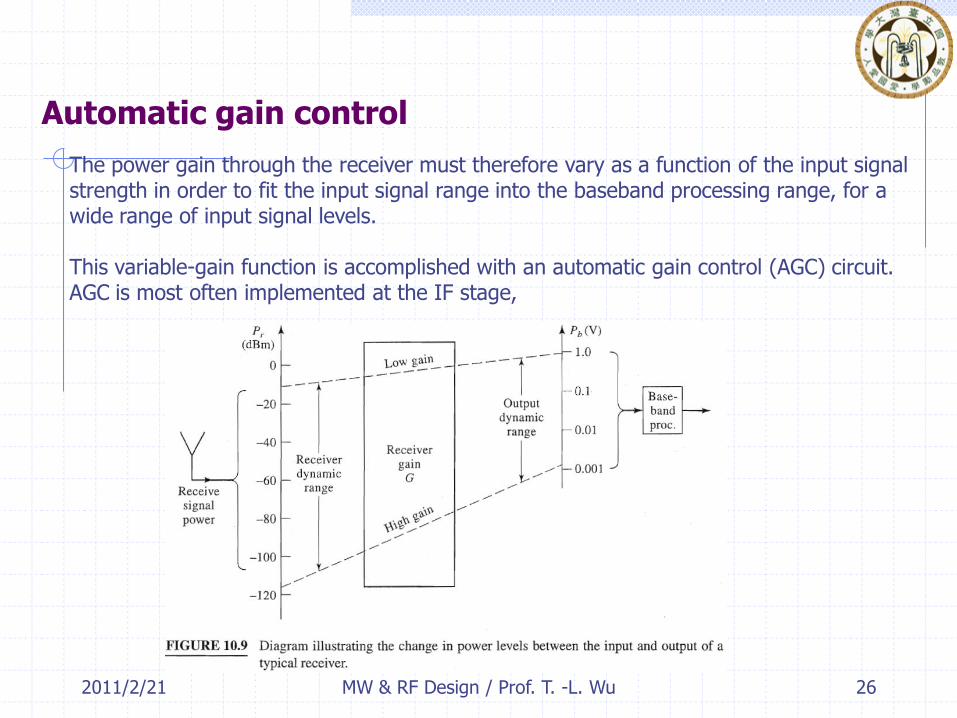
Automatic gain control
26MW & RF Design / Prof. T. -L. Wu
The power gain through the receiver must therefore vary as a function of the input signal strength in order to fit the input signal range into the baseband processing range, for a wide range of input signal levels.
This variable-gain function is accomplished with an automatic gain control (AGC) circuit. AGC is most often implemented at the IF stage,

2011/2/21 27MW & RF Design / Prof. T. -L. Wu
It consists of a variable voltage controlled attenuator (or variable gain amplifier) with a detector to convert a sample of the IF voltage to a DC value.
The rectified signal is then compared with a reference level, and passed through a low-pass filter to provide a time constant long enough to avoid having the AGC following low-frequency components of the modulated signal.

2011/2/21 MW & RF Design / Prof. T. -L. Wu 28
Compression and Third-order Intermodulation
Power exceed P1 dB will cause harmonic distortionPower exceed IP3 will cause intermodulation distortion
It is important to track power levels through the stages of the receiver to ensure that P1 and P3 are not exceeded.
Placing an AGC attenuator in the RF stage may reduce the possibility of saturatingthe RF amplifier with a large input signal, but will degrade the noise performance of thereceiver, even for a low attenuator setting.

2011/2/21 29MW & RF Design / Prof. T. -L. Wu
2011/2/21
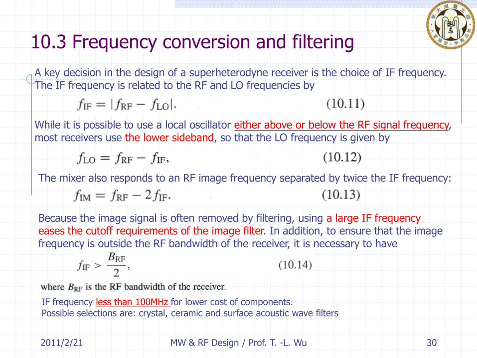
10.3 Frequency conversion and filtering
IF frequency less than 100MHz for lower cost of components.Possible selections are: crystal, ceramic and surface acoustic wave filters
30MW & RF Design / Prof. T. -L. Wu
A key decision in the design of a superheterodyne receiver is the choice of IF frequency.The IF frequency is related to the RF and LO frequencies by
While it is possible to use a local oscillator either above or below the RF signal frequency,most receivers use the lower sideband, so that the LO frequency is given by
The mixer also responds to an RF image frequency separated by twice the IF frequency:
Because the image signal is often removed by filtering, using a large IF frequency eases the cutoff requirements of the image filter. In addition, to ensure that the image frequency is outside the RF bandwidth of the receiver, it is necessary to have

2011/2/21
Filtering
31MW & RF Design / Prof. T. -L. Wu
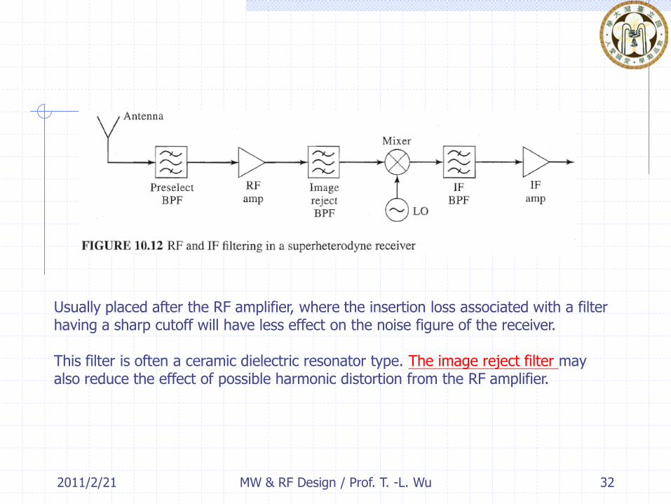
Filtering is required in a superheterodyne receiver to provide interference rejection,image rejection, selectivity, and suppression of LO radiation.
A preselect filter
This is a bandpass filter set to the RF tuning range of the receiver.
It rejects out-of-band interference, which is particularly important for preventing strong interference signals from saturating the RF amplifier or mixer.
In order to keep the noise figure as low as possible, this filter should have a low insertion loss. This implies that its cutoff characteristics will not be very sharp, so this filter generally does not provide much rejection of the image frequency.
2011/2/21 MW & RF Design / Prof. T. -L. Wu 32
Usually placed after the RF amplifier, where the insertion loss associated with a filter having a sharp cutoff will have less effect on the noise figure of the receiver.
This filter is often a ceramic dielectric resonator type. The image reject filter mayalso reduce the effect of possible harmonic distortion from the RF amplifier.

2011/2/21 MW & RF Design / Prof. T. -L. Wu 33
Because the local oscillator frequency is separated from the RF frequency only by theIF frequency, it often lies in the RF passband of the receiver, and may pass back through the RF stages to be radiated by the antenna.
Such radiation may interfere with other users, and therefore must be attenuated to a very low level. This is usually accomplished by the combined attenuation of the preselect and image reject filters, the LO-RF isolation of the mixer, and the reverse attenuation of the RF amplifier.
Because the LO is only one IF frequency away from the RF frequency, while the image is twice the IF frequency away, it is sometimes more difficult to meet the requirement for low LO radiation than it is for image rejection.
LO Radiation (Leakage)
2011/2/21 MW & RF Design / Prof. T. -L. Wu 34
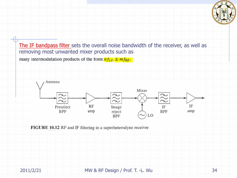
The IF bandpass filter sets the overall noise bandwidth of the receiver, as well asremoving most unwanted mixer products such as
2011/2/21
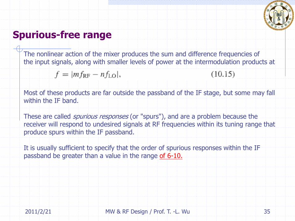
Spurious-free range
35MW & RF Design / Prof. T. -L. Wu
The nonlinear action of the mixer produces the sum and difference frequencies ofthe input signals, along with smaller levels of power at the intermodulation products at
Most of these products are far outside the passband of the IF stage, but some may fall within the IF band.
These are called spurious responses (or "spurs"), and are a problem because the receiver will respond to undesired signals at RF frequencies within its tuning range that produce spurs within the IF passband.
It is usually sufficient to specify that the order of spurious responses within the IF passband be greater than a value in the range of 6-10.
2011/2/21 MW & RF Design / Prof. T. -L. Wu 36
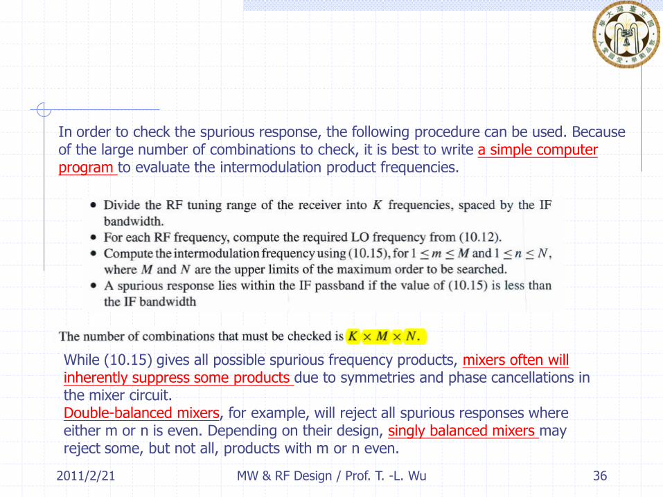
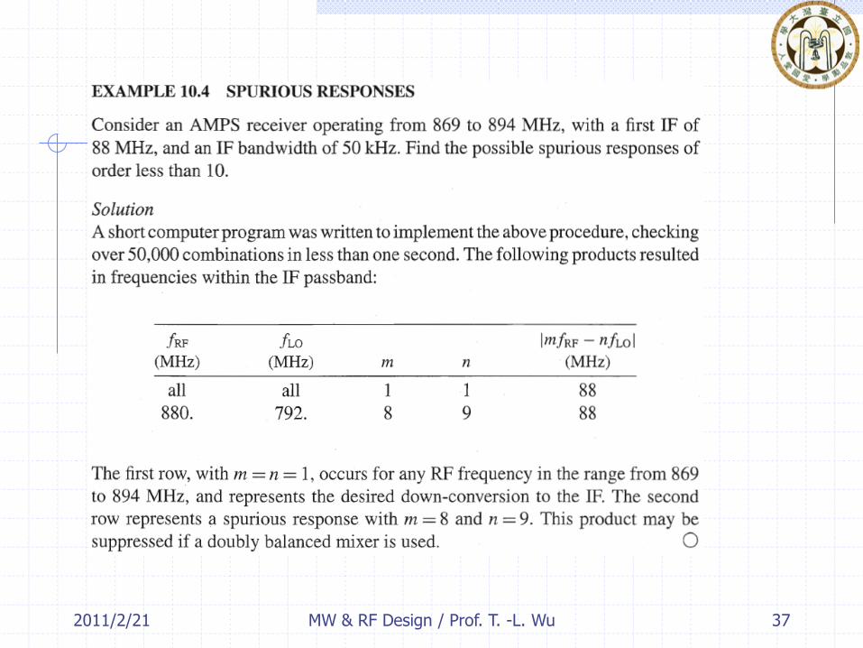
In order to check the spurious response, the following procedure can be used. Becauseof the large number of combinations to check, it is best to write a simple computer program to evaluate the intermodulation product frequencies.
While (10.15) gives all possible spurious frequency products, mixers often will inherently suppress some products due to symmetries and phase cancellations in the mixer circuit.Double-balanced mixers, for example, will reject all spurious responses where either m or n is even. Depending on their design, singly balanced mixers may reject some, but not all, products with m or n even.
2011/2/21 37MW & RF Design / Prof. T. -L. Wu
2011/2/21
10.4 Example of practical receivers
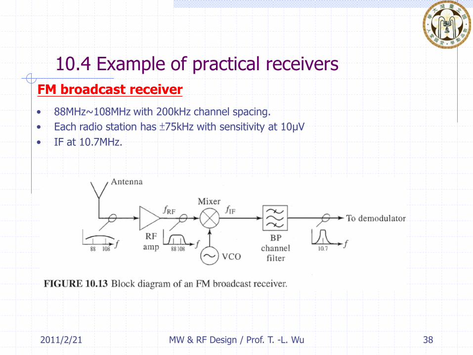
FM broadcast receiver
• 88MHz~108MHz with 200kHz channel spacing.
• Each radio station has ±75kHz with sensitivity at 10μV
• IF at 10.7MHz.
38MW & RF Design / Prof. T. -L. Wu
2011/2/21 MW & RF Design / Prof. T. -L. Wu 39
the RF amplifier usually provides a small amount of bandpass filtering to reject signals far outside the FM band.
The desired channel cannot be tuned at the RF stage, however, because the required tunable filter bandwidth of 150 kHz/100 MHz = 0.15% cannot be inexpensively realized in practice.
Selectivity is then provided by the IF bandpass filter, with a fixed center frequency of 10.7 MHz. The fractional bandwidth of this filter is about 150 kHz/l0.7 MHz= 1.4%, which can be easily realized.
2011/2/21
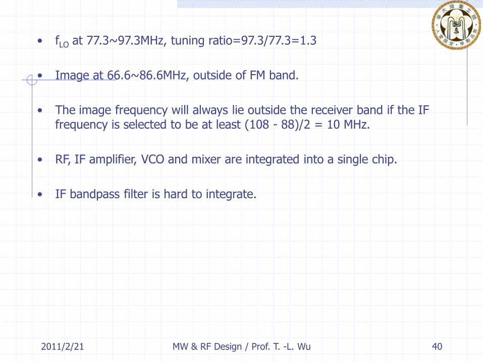
• fLO at 77.3~97.3MHz, tuning ratio=97.3/77.3=1.3
• Image at 66.6~86.6MHz, outside of FM band.
• The image frequency will always lie outside the receiver band if the IF frequency is selected to be at least (108 - 88)/2 = 10 MHz.
• RF, IF amplifier, VCO and mixer are integrated into a single chip.
• IF bandpass filter is hard to integrate.
40MW & RF Design / Prof. T. -L. Wu

2011/2/21 MW & RF Design / Prof. T. -L. Wu 41
Engineers at Philips in the 1980s to propose the innovative idea of lowering the IF frequency from 10.7 MHz to 70 kHz.
This converts the desired FM channel down to baseband (0 to 70 kHz), so channel selectivity can be obtained with a low-pass filter, which can be easily implemented with active integrated circuitry.
The image frequency in this case is located 2 fIF = 140 kHz away from the desired RF channel, placing it between the selected channel and the next lower channel.
The image signal therefore is not attenuated by the RF amplifier or preselect filter (if one is used).
The noise from the image bandwidth will reduce the receiver SNR by 3 dB. This is a trade-off in performance for a very high degree of miniaturization-FM receivers of this type can be made as small as a wristwatch.
2011/2/21
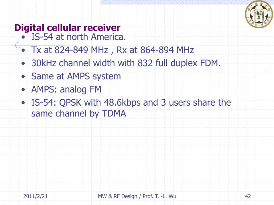
Digital cellular receiver• IS-54 at north America.
• Tx at 824-849 MHz , Rx at 864-894 MHz
• 30kHz channel width with 832 full duplex FDM.
• Same at AMPS system
• AMPS: analog FM
• IS-54: QPSK with 48.6kbps and 3 users share the same channel by TDMA
42MW & RF Design / Prof. T. -L. Wu

2011/2/21
Image at (869-894)-2(87)= 695-720MHZ
43MW & RF Design / Prof. T. -L. Wu

2011/2/21
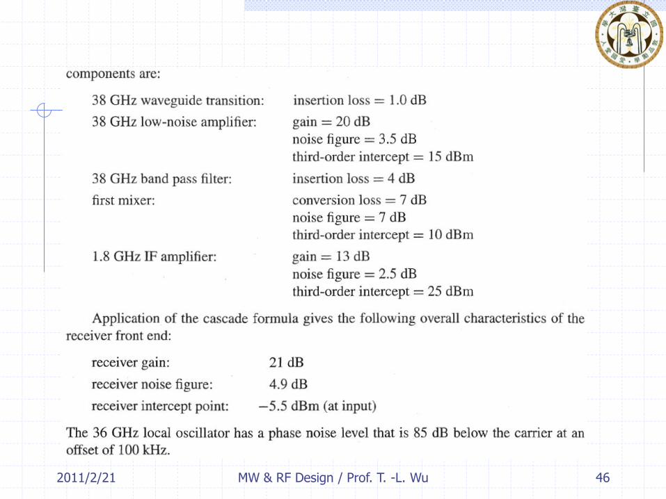
Millimeter Wave Point-to-Point Radio Receiver
• Base station to MTSO (mobile telephone switching offices) and PSTN
• High data rate and good reliability required.
• More economic then fiber or coaxial cable.
台大校門口 44MW & RF Design / Prof. T. -L. Wu

2011/2/21
Tx
Rx
45MW & RF Design / Prof. T. -L. Wu
2011/2/21 46MW & RF Design / Prof. T. -L. Wu
2011/2/21
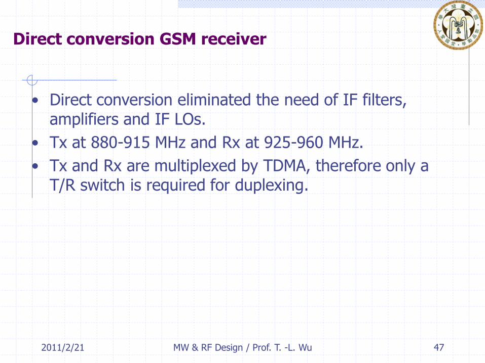
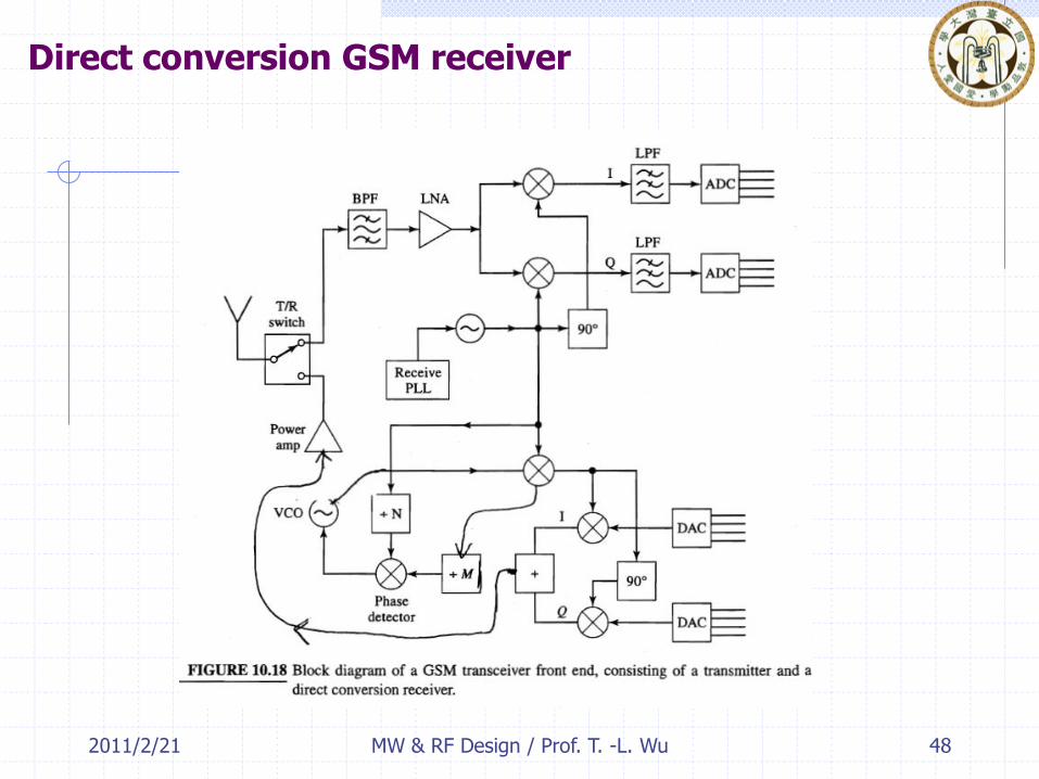
Direct conversion GSM receiver
• Direct conversion eliminated the need of IF filters, amplifiers and IF LOs.
• Tx at 880-915 MHz and Rx at 925-960 MHz.
• Tx and Rx are multiplexed by TDMA, therefore only a T/R switch is required for duplexing.
47MW & RF Design / Prof. T. -L. Wu
2011/2/21
Direct conversion GSM receiver
48MW & RF Design / Prof. T. -L. Wu
2011/2/21
Jan. 5, 2008
49MW & RF Design / Prof. T. -L. Wu