Realiser A16 Manual - SMYTH ResearchThe Realiser A16 is defined by its firmware, which is updated...
130
The Realiser A16 is defined by its firmware, which is updated from time to time with refinements and new features. Likewise the manual is updated to conform with new firmware, and to provide additional information. Current firmware and the current manual are available on the Smyth Research website at: www.smyth-research.com/downloads Please check regularly for firmware and manual updates and keep both current. There may be significant differences between the operation described here and that for other firmware versions. Realiser A16 Manual Mathew Kane Manual v0.91 for A16 firmware v1.02 8/29/19
Transcript of Realiser A16 Manual - SMYTH ResearchThe Realiser A16 is defined by its firmware, which is updated...

The Realiser A16 is defined by its firmware, which is updated from time to time with refinements and new features. Likewise the manual is updated to conform with new firmware, and to provide additional information. Current firmware and the current manual are available on the Smyth Research website at: www.smyth-research.com/downloads Please check regularly for firmware and manual updates and keep both current. There may be significant differences between the operation described here and that for other firmware versions.
Realiser A16 Manual
Mathew Kane
Manual v0.91 for A16 firmware v1.02
8/29/19

1 | P a g e
Contents
1 Safety 6
Firmware update 9
2 Introduction 11
Realiser A16 operational design 11
2.1.1 The Problem: Listening to multichannel audio over headphones. 11
2.1.2 The Solution: Realiser A16 11
2.1.3 Realiser A16 specifications 11
Realiser A16 operational overview 12
2.2.1 Presets 12
2.2.2 Listening Rooms 12
2.2.3 PRIRs 12
Unpacking and parts assembly 14
2.3.1 Unpacking 14
Part Names and Functions 22
2.4.1 Front panel of the Realiser A16-2U 22
2.4.2 Rear panel of the Realiser A16-2U 23
2.4.3 Realiser A16 Remote control 24
2.4.4 Head-tracker: Head-top and IR Reference Set-top 25
Quick start 30
3 Initial power up 31
Power On Sequence 31
3.1.1 Splash screen 31
3.1.2 Hardware tests 31
3.1.3 Loading and running Presets 31
3.1.4 Displaying the Speaker Map for User A preset 32
3.1.5 Listening to the Internal Audio Test Loop 32
4 Menu Navigation 34
The Home Page menu 34
Navigating the menus, selecting options and changing values with the remote control 34
4.2.1 Menu option selection: 34
4.2.2 Selecting values in a menu option: 34
Moving between menu levels using the ENTER and BACK keys 35
4.3.1 The ENTER symbol: 35
4.3.2 Menu continuation symbols: ↓ and ↑ 35
4.3.3 The BACK key: 35
Accessing the Preset Speaker Map page 36
4.4.1 The PA and PB key 36
4.4.2 Changing Presets from the Speaker Map page: 36
4.4.3 The Menu key: 36

2 | P a g e
5 Settings 37
PRIR Sound Rooms 37
5.1.1 PRIR room 1 loc 37
5.1.2 PRIR room 1 desc 38
5.1.3 PRIR room 1 speaker setup 38
Headphones 39
5.2.1 SVS Bass 39
System 40
5.3.1 Assign solo buttons 40
5.3.2 HT Settings 40
5.3.3 Measurement Settings 42
5.3.4 Volume settings 42
5.3.5 LCD off timer 43
5.3.6 Default HDMI input 43
5.3.7 Full factory restore 44
5.3.8 Factory Tests 44
Time 44
Users 44
Updates/About 45
5.6.1 Check for updates at power-up 45
5.6.2 Generate log file 45
Restore factory setup 45
6 File Management 47
Files menu 47
Memory locations 47
PRIR files menu 47
6.3.1 Location 48
6.3.2 Layout, Subject, Date 48
6.3.3 Copy to SD card menu and Delete menu 48
HPEQ files menu 49
6.4.1 Phones, Subject, Time 49
6.4.2 Content 49
6.4.3 Copy to SD card menu and Delete menu 49
7 Configuring a Preset for SVS headphone or AV mode 51
The Home Page Menu 51
The Preset Menu 52
7.2.1 Select the Preset number 52
7.2.2 Set the SVS Rendering Mode 53
7.2.3 Verify the User 53
7.2.4 Select the Atmos, DTS:X and PCM listening rooms for this preset number 53
7.2.5 Toggle the AV mode ON or OFF 53
7.2.6 HPEQ menu 53
7.2.7 PCM Audio management 54

3 | P a g e
7.2.8 Legacy Dolby decode 54
7.2.9 Legacy DTS decode 55
7.2.10 Dolby night mode 55
7.2.11 DTS night mode 55
7.2.12 Dolby Surround 55
7.2.13 DTS Neural:X 55
Load and Activate presets for User A and User B 55
Audio Meters 56
7.4.1 Elements of the Speaker Map display for any preset (Figure 7-11) 56
7.4.2 Controls associated with the Speaker Map display 57
8 Measuring a new PRIR in a sound room using the synchronous (ALL) method 62
Configure the PRIR Sound room 62
8.1.1 Edit the PRIR room 1 location (loc) 63
8.1.2 Edit the PRIR room 1 description (desc) 63
8.1.3 Configure the PRIR room 1 speaker setup 63
8.1.4 Configure the measurement settings 64
8.1.5 Connect the A16 to the loudspeakers in the sound room 65
8.1.6 Connect the binaural microphones to the A16 65
8.1.7 Insert the binaural microphones in the ear canal 65
Configure and run the loudspeaker calibration routine 65
8.2.1 Set the subject name, room name and headphone name 65
8.2.2 Set the loudspeakers to be calibrated 66
8.2.3 Run the Speaker Calibration routine 66
Configure and run the PRIR Measurement routine 67
8.3.1 Subject and Room names 68
8.3.2 Select the loudspeakers to be measured 68
8.3.3 Configure the look angles for the PRIR measurements 68
8.3.4 Set the measurement mode 70
8.3.5 Set the sweep type 70
8.3.6 Load and run the PRIR measurement routine 70
8.3.7 Saving the PRIR measurement 72
9 Measuring personalised headphone EQ filters 73
9.1.1 AutoEQ filter measurement using binaural microphones 73
9.1.2 FlatEQ filter generation for IEM-type headphones 73
9.1.3 Manual EQ modification of either the autoEQ or flatEQ filters 73
Configure the A16 for an automatic HPEQ measurement of normal headphones. 73
9.2.1 Connect the binaural microphones to the A16 73
9.2.2 Set the headphone A output gain 73
9.2.3 Connect headphones to the User A HP jack 73
Configure the HPEQ options 74
9.3.1 Set the Subject name and Headphone name 74
9.3.2 Set the HPEQ measurement options 74
Saving the HPEQ measurement 76

4 | P a g e
76
Configure the A16 to generate a flat HPEQ filter. 76
9.5.1 Set the Subject name and Phones name 76
9.5.2 Set the HPEQ measurement options 76
Manual HPEQ adjustment using an external loudspeaker as reference. 77
9.6.1 Set the HPEQ measurement options 77
Manual HPEQ adjustment using an equal loudness curve. 79
9.7.1 Set the HPEQ measurement options 79
10 Configuring a Listening Room from one or more PRIRs 81
Select the room type: Atmos, DTS:X or PCM 81
Configure the selected listening room 81
10.2.1 Select a room number 81
10.2.2 Unlock a room to change its configuration 81
10.2.3 Set the Listening Mode 82
Select virtual speakers for a Listening Mode from a PRIR file 83
10.3.1 Select one matching speaker 83
10.3.2 Select all matching speakers 84
10.3.3 Normalise speaker volumes 85
Set Bass Management / Tactile outputs / Stereo mixdown outputs 86
10.4.1 Dolby Atmos and DTS:X listening rooms 86
10.4.2 PCM listening rooms 86
10.4.3 Bass Management for Dolby Atmos or DTS:X listening rooms 86
10.4.4 Bass Management for PCM listening rooms 87
10.4.5 Limit Reverb 88
10.4.6 Tactile (mixdown) 88
10.4.7 Stereo (mixdown) 89
General notes for Configuring a Listening Room 89
11 Appendix A: Listening rooms loudspeaker configurations 90
Dolby Atmos Listening Rooms loudspeaker configurations 90
DTS:X listening rooms loudspeaker configurations 92
PCM listening rooms loudspeaker configurations 94
12 Appendix B: Loudspeaker names and labels 95
Loudspeaker names and labels with default azimuth and elevation angles 95
Graphical representation of loudspeakers in the Speaker Map display of the A16 97
Graphical representation of speaker positions: loudspeaker names and ID numbers 98
13 Appendix C: Calibrating the magnetic sensor in the head-top device 99
14 Appendix D: Setting up the head-tracker 101
15 Appendix E: Testing the binaural microphones using HP-B output 106
16 Appendix F: The Async mode for measuring a PRIR 107
17 Appendix G: Updating the Realiser A16 firmware 108
18 Appendix H: Updating the Factory-PRIR and Factory-HPEQ files 110
19 Appendix I: Updating the Head-top head-tracking firmware 111
20 Appendix J: Connections 115

5 | P a g e
21 Appendix J: Bass Management 117
Atmos / DTS:X AV bass management ON (HDMI, Coaxial) (HP DB disabled) 117
Atmos / DTS:X AV bass management OFF (HDMI, Coaxial) (HP DB disabled) 118
Atmos / DTS:X AV bass management ON (HDMI, Coaxial) (HP DB enabled) 119
Atmos / DTS:X AV bass management OFF (HDMI, Coaxial) (HP DB enabled) 120
PCM ‘Direct’ bass management (USB, Line) 121
PCM ‘Virtual’ bass management (USB, Line) 122
PCM bass management ‘OFF’ 123
22 Appendix K: Tactile management (all inputs) 124
23 Appendix L: Stereo mix-down 125
24 Appendix M: Manual Headphone EQ 126
Manual headphone EQ using an external loudspeaker as reference 126
Manual headphone EQ using an equal loudness curve 126
25 Appendix N: Tri-volume headphone output 127
26 Appendix O: Diagnostic displays 128
Audio source diagnostics 128
Preset speaker map information 128
26.2.1 Listening mode and multichannel line outputs 128
Audio input and output levels 129

6 | P a g e
1 Safety
IMPORTANT SAFETY INSTRUCTIONS
READ BEFORE OPERATING EQUIPMENT
• Read these instructions.
• Keep these instructions.
• Heed all warnings.
• Follow all instructions.
• Do not use this apparatus near water.
• Clean only with a dry cloth.
• Install in accordance with the manufacturer’s instructions.
• Do not install near any heat sources such as radiators, heat registers, stoves or other apparatus
(including amplifiers) that produce heat.
• Protect the power cord from being walked on or pinched particularly at plugs, convenience
receptacles, and the point where they exit from the apparatus.
• Only use attachments/accessories specified by the manufacturer.
• Unplug this apparatus during lightning storms or when unused for long periods of time.
• Refer all servicing to qualified service personnel. Servicing is required when the apparatus has been
damaged in any way, such as power-supply cord or plug is damaged, liquid has been spilled or objects
have fallen into the apparatus, the apparatus has been exposed to rain or moisture, does not operate
normally, or has been dropped.
• Never expose the equipment to rain or a high level of humidity. For this reason do not install it in the
immediate vicinity of swimming pools, showers, damp basement rooms or other areas with unusually
high atmospheric humidity.
• Do not use the device/s outside. To reduce the risk of fire or electric shock, do not expose this/these

7 | P a g e
device/s to rain or moisture.
• Never place objects containing liquid (e.g. vases or drinking glasses) on the equipment. Liquids in the
equipment could cause a short circuit.
• Lay all connection cables so that they do not present a trip hazard.
• Check whether the specifications comply with the existing mains supply. Serious damage could occur
due to connecting the system to the wrong power supply. An incorrect mains voltage could damage the
equipment or cause an electric shock.
• Never place open flames near the equipment.
• If the equipment causes a blown fuse or a short circuit, disconnect it from the mains and have it
checked and repaired.
• Do not open the equipment without authorisation. You could receive an electric shock. Leave all
service work to authorised expert personnel.
• Do not hold the mains cable with wet hands. There must be no water or dust on the contact pins. In
both cases you could receive an electric shock.
• The mains cable must be firmly connected. If it is loose there is a fire hazard.
• Always pull out the mains cable from the mains and/or from the equipment by the plug, never by the
cable. The cable could be damaged and cause an electric shock or fire.
• If the power cable is connected, avoid contact of the unit with other metallic objects.
• Do not insert objects into openings. You could damage the equipment and/or injure yourself.
• Do not use the equipment if the mains plug is damaged.
• When installing the device into a 19" rack, make sure that the mains switch, mains plug and all
connection on the rear of the device are easily accessible.
• When connecting the headphone do not place the headphone on your head until you are sure that
there is no sound being played.
• When connecting the headphone, ensure that the volume is turned down to minimum. Adjust the

8 | P a g e
volume after putting on the headphone. Do not set the volume too high, because you could
permanently damage your hearing. Over time you may adapt to a high volume of sound but it can still
cause hearing damage.
• Connecting and disconnecting cables, choosing menu items, and any adjustments should be done at a
low volume setting and with the headphones off your head, to avoid sounds that could cause hearing
damage.
• With wired headphones you should avoid sharp movements, which could cause the headphone to fall
off your head. You could be seriously injured especially if you are wearing pierced earrings, spectacles
etc. The cable could wind around your neck and cause strangulation.
• Take the headphones off when changing presets, until you are familiar with the presets.
9 | P a g e
Firmware update Updating the firmware of the A16 is only necessary if the A16’s current firmware is older than the latest downloadable version. The current revision of the firmware is found in ‘Updates/About’ accessed via the ‘Settings’ page as described below in step 6. If an update is required please begin with step 1.
STEP 1. The new firmware for the Realiser A16 is uploaded through the micro-SD card slot on the front panel. First, obtain a micro-SD card (commonly 8 or 16 GB) and ensure it is formatted as FAT32. Second, create a ‘Realiser’ folder in the root directory and copy the firmware file FIRMA001.SVS into the Realiser folder. Insert this micro-SD card into the slot on the front of your A16.
STEP 2. Power up the A16 ensuring the power indicator LED is steady green. You can power it up using the remote control or by momentarily depressing either User A or User B volume knobs. Now turn off the A16 by pushing in and holding in the User A volume knob for at least 3 seconds. The LCD screen will switch off and the power indicator LED will turn red. Release the User A volume knob.
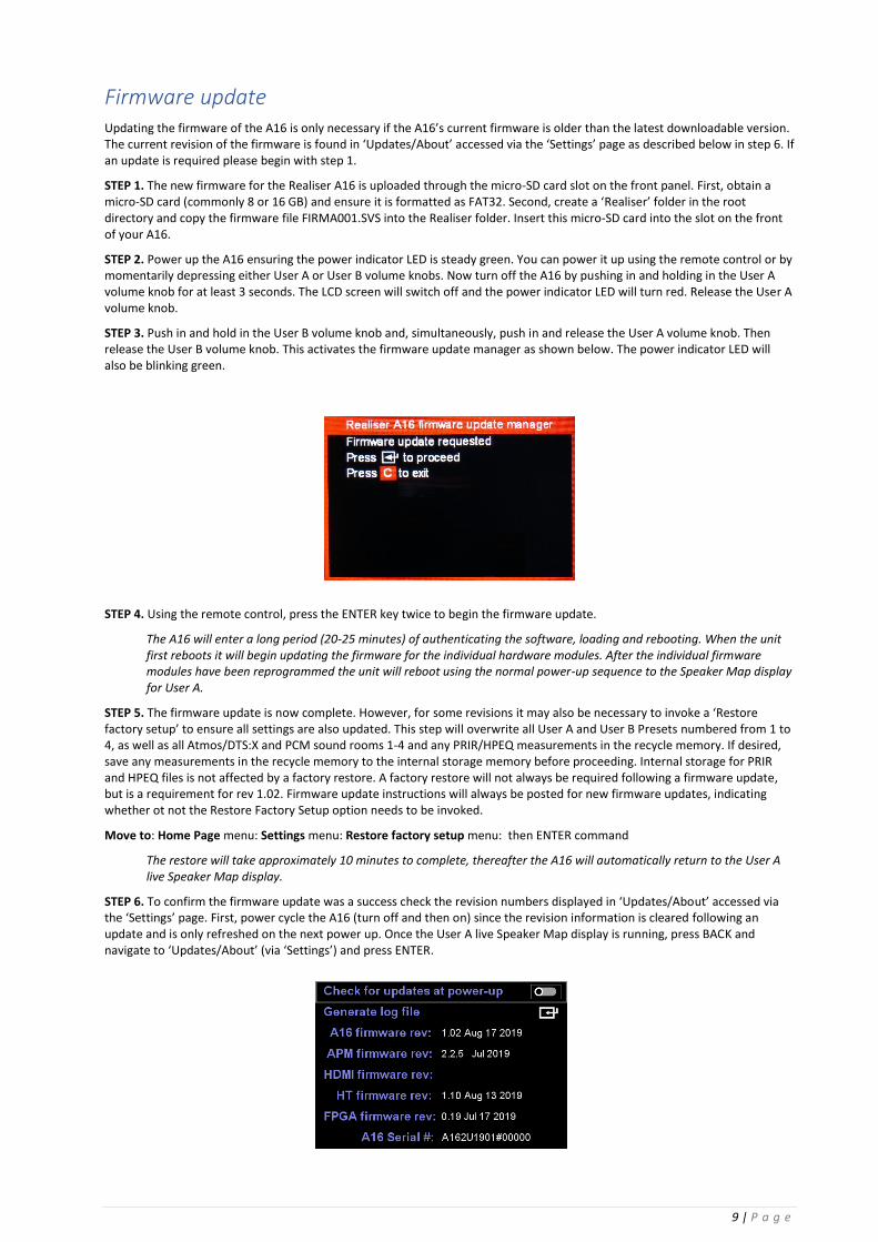
STEP 3. Push in and hold in the User B volume knob and, simultaneously, push in and release the User A volume knob. Then release the User B volume knob. This activates the firmware update manager as shown below. The power indicator LED will also be blinking green.
STEP 4. Using the remote control, press the ENTER key twice to begin the firmware update.
The A16 will enter a long period (20-25 minutes) of authenticating the software, loading and rebooting. When the unit first reboots it will begin updating the firmware for the individual hardware modules. After the individual firmware modules have been reprogrammed the unit will reboot using the normal power-up sequence to the Speaker Map display for User A.
STEP 5. The firmware update is now complete. However, for some revisions it may also be necessary to invoke a ‘Restore factory setup’ to ensure all settings are also updated. This step will overwrite all User A and User B Presets numbered from 1 to 4, as well as all Atmos/DTS:X and PCM sound rooms 1-4 and any PRIR/HPEQ measurements in the recycle memory. If desired, save any measurements in the recycle memory to the internal storage memory before proceeding. Internal storage for PRIR and HPEQ files is not affected by a factory restore. A factory restore will not always be required following a firmware update, but is a requirement for rev 1.02. Firmware update instructions will always be posted for new firmware updates, indicating whether ot not the Restore Factory Setup option needs to be invoked.
Move to: Home Page menu: Settings menu: Restore factory setup menu: then ENTER command
The restore will take approximately 10 minutes to complete, thereafter the A16 will automatically return to the User A live Speaker Map display.
STEP 6. To confirm the firmware update was a success check the revision numbers displayed in ‘Updates/About’ accessed via the ‘Settings’ page. First, power cycle the A16 (turn off and then on) since the revision information is cleared following an update and is only refreshed on the next power up. Once the User A live Speaker Map display is running, press BACK and navigate to ‘Updates/About’ (via ‘Settings’) and press ENTER.

10 | P a g e
Confirm the A16 firmware revision is the version that has been downloaded from the A16 website. The APM runs the Dolby Atmos decoder and this firmware revision should show 2.2.5 Jul 2019.
STEP 7. The firmware update is now complete. Repeatedly press the BACK key to return to the Home Page menu.

11 | P a g e
2 Introduction
Realiser A16 operational design
2.1.1 The Problem: Listening to multichannel audio over headphones.
The Realiser A16 has been designed primarily to allow multichannel immersive audio to be heard accurately through stereo headphones.
Today, almost all immersive audio content is monitored over loudspeakers during production, not through headphones, and therefore loudspeaker reproduction, in an acoustically controlled room, is still the preferred method for listening to immersive audio.
For headphones to accurately mimic loudspeakers, digital signal processing must be used to create multiple virtual loudspeakers in a virtual acoustic environment. The individual audio signals are filtered through these virtual loudspeakers and room, and then summed together to create a 2-ch binaural signal suitable for reproduction over headphones.
If the virtual loudspeakers filters are personalised to an individual, the final reproduction through headphones is remarkably accurate when compared directly to the loudspeaker reproduction: the spatial positioning of each source is maintained, stereo imaging between the virtual speakers is preserved, and the reverberation of the room and the overall timbre of the sound is the same.
For an even more naturalistic listening experience head-tracking is also required, while personalised headphone equalisation help to preserve the quality of the virtualisation over a wide range of headphones.
2.1.2 The Solution: Realiser A16
The Realiser A16 allows users to measure up to 16 virtual loudspeakers in any spatial position around the user, in any room, and create virtual listening rooms in almost any format from these measurements. Head-tracking is enabled by default, and methods are included to equalise stereo headphones and in-ear monitors for an individual.
Immersive audio signals can be sourced and decoded internally from Dolby Atmos through HDMI, from stereo and multi-channel PCM through HDMI, SPDIF and USB, and from stereo and multichannel analogue inputs.
These source signals are convolved with matching virtual binaural loudspeakers, summed to left ear and right ear signals, equalised and then output to headphones. The result is an accurate reproduction of the multichannel audio source, suitable for professional monitoring of any immersive 16-ch audio format.
2.1.3 Realiser A16 specifications
SVS loudspeaker virtualisation with integrated headtracking (16ch 32bit floating-point processing@48kHz sampling rate, processing latency 32ms, maximum reverb length 750ms). All source signals above a sampling rate of 48kHz are down-sampled to 48kHz.
Virtualisation sources:
1. HDMI inputs (1-4): Dolby Atmos decoded bitstream (16ch), 8ch LPCM (24bit@48/96/192kHz)
2. SPDIF inputs (coaxial and optical): 2ch LPCM (24bit@48/96/192kHz) and Dolby Digital bitstream
3. USB 2.0 input: 16ch LPCM (24bit@48/96/192kHz)
4. Analogue line inputs: 16ch (24bit@48kHz)
5. Stereo line inputs: 2ch (24-bit@48kHz)

12 | P a g e
Realiser A16 operational overview
⚫ The A16 runs on Presets – each preset contains three different Listening Rooms.
⚫ Listening Rooms are designed for specific decoding formats, and for specific loudspeaker arrangements within these formats. Listening rooms contain a maximum of 16 virtual loudspeakers.
⚫ PRIRs contain the binaural room impulse measurement data from real loudspeaker sources that is used to generate virtual loudspeakers. PRIRs can contain measurements from up to 64 virtual sources.
2.2.1 Presets
Presets contain multiple Listening Rooms. This allows the A16 processor to switch automatically between different loudspeaker reproduction formats, depending on the detected bitstream, Dolby, DTS or PCM.
2.2.2 Listening Rooms
A Listening Room contains up to 16 virtual loudspeakers arranged in a single defined format, with the virtual loudspeakers being created from one or more PRIRs. The Listening Room controls the output format of the decoded immersive audio signals, and also contains parameters for room related controls such as bass management. The Listening Room also controls switching between SVS headphone mode and AV loudspeaker mode – in the AV mode the SVS processing is bypassed, and the decoded multichannel outputs signals are sent directly to the 16-ch analogue Line Outputs.
2.2.3 PRIRs
PRIRs contain raw unprocessed data of binaural room impulse response measurements, taken either by an individual or a dummy head, in a real sound room, using one or more real loudspeaker sources. In order to allow for head-tracking each PRIR data set consists of binaural measurements from multiple head orientations (also described as ‘look angles’). A single PRIR can contain up to 64 ‘virtual’ loudspeakers and up to 23 look angles for each of these speakers.
PRIRs are measurements of binaural
room impulse responses of real loudspeakers in a real room
Listening Room #3
Presets
contain three Listening Rooms and run on a DSP
PRIR#3 PRIR#2
Listening Rooms
are constructed from one or more PRIRs
Listening Room #1
PRIR#4 PRIR#1
Figure 2-1 Operational flow of the Realiser A16

13 | P a g e
Figure 2-2 Operational overview of the Realiser A16 with audio input from an HDMI source. Audio can also be sourced from stereo and multichannel analogue inputs, digitally via SPDIF, or from a computer via USB 2.0.

14 | P a g e
Unpacking and parts assembly
2.3.1 Unpacking The Realiser A16 package contains the items below.
Main processor components:
1. Realiser A16 processor (either the 2U 19” rack-mountable version or the HS version)
2. Power Supply (input 100-240V AC, 50/60 Hz, output 12V DC @ 3A) *
3. IR remote control
Set-top head-tracking components:
4. Set-top IR reference unit (for head-tracking)
5. Set-top cable (3.5mm plug to 3.5mm plug, 4-pole)
6. Set-top extension cable (3.5mm socket to 3.5mm plug, 4-pole)
Head-top head-tracking components:
7. Head-top head-tracker
8. Clip for mounting the head-top to headphones
9. Rubber bands (for connecting head-top clip to headphones - 3 sizes)
10. Head-top cable (2.5mm plug to 2.5mm plug, 4-pole)
11. Head-top extension cable (2.5mm socket to 2.5mm plug, 4-pole)
12. Cable clips (to attach the head-top cable to the headphone cable)
Measurement microphone components:
13. Lanyard (orange neck strap)
14. Clip for lanyard (for supporting in-ear microphones during PRIR measurements)
15. In-ear microphones (one pair)
16. Foam earplugs (for microphones - 3 sizes)
17. Grounding wrist strap (for earthing body during PRIR measurements)
18. Head-band for mounting a Head-top device during PRIR measurements
For the Realiser A16 2U processor there is an optional accessory.
Optional accessories:
19. 2U 19” rack-mount ears
* The power supply is designed for any mains voltage and frequency, and is provided with a mains plug appropriate for the
market to which the Realiser is shipped.

15 | P a g e
2.3.1.1 Unpacking: Main processor components
Figure 2-3: Realiser A16 processor (either a 2U (left) or HS (right) version)
Figure 2-4 Universal power supply (100-240V, 50/60Hz)
Figure 2-5 Remote control (IR)

16 | P a g e
2.3.1.2 Unpacking: Set-top head-tracking components
Figure 2-6: Set-top IR reference for head-tracking
Figure 2-7: Set-top cable (3.5mm plug to 3.5mm plug, 4-pole)
Figure 2-8: Set-top extension cable (3.5mm socket to 3.5mm plug, 4-pole)

17 | P a g e
2.3.1.3 Unpacking: In-ear measurement microphone components
Figure 2-9: Lanyard (for supporting microphones during measurements)
Figure 2-10: Microphone cable support clip (connects to the lanyard and
provides strain relief to the microphones when inserted in the ear canals)
Figure 2-11: In-ear measurement microphones (one pair)

18 | P a g e
Unpacking: In-ear measurement microphone components (cont.)
Figure 2-12: Ear foam (seals the microphones when inserted
in the ear canal – 4 pairs in 3 sizes)
Figure 2-13: Grounding wrist-strap (used during microphone measurements
to reduce body-induced hum)
Figure 2-14: Head-band

19 | P a g e
2.3.1.4 Unpacking: Head-top head-tracking components
Figure 2-15: Head-top head-tracking device
Figure 2-16: Clip for mounting the head-top device
(connects to the headphone head-band)
Figure 2-17: Rubber bands (3 sizes)
(connects the clip to a headphone head-band)

20 | P a g e
Unpacking: Head-top head-tracking components (cont.)
Figure 2-18: Head-top cable (2.5mm plug (RA) to 2.5mm plug, 4-pole
Figure 2-19: Head-top extension cable (2.5mm socket to 2.5mm plug, 4 pole)
Figure 2-20: Cable clips to connect the head-top cable to the headphone cable
(3 sizes for circular headphone cables, 2 sizes for flat headphone cables)

21 | P a g e
2.3.1.5 Unpacking: Optional accessories
Figure 2-21: 19” rack-mount ears (for the 2U version of the Realiser A16)

22 | P a g e
Part Names and Functions
2.4.1 Front panel of the Realiser A16-2U
Figure 2-22: Front panel of the Realiser A16-2U
The Realiser A16-2U front panel has the following elements (from right to left):
LCD display – a 480 x 320 pixel full colour LCD panel
micro SD card slot and activity light – for external storage of PRIR and HPEQ files, and for firmware upgrades. The activity light is in the left-hand corner of the uSD slot opening.
USB OTG port – digital headphone output (not currently operational)
MIC jacks (L and R) – for in-ear binaural measurement microphones (2 x 3.5mm 4-pole sockets)
GAME port – for a stereo headphone output signal and mono microphone input signal (3.5mm 4-pole socket)
IR receiver window – for receiving remote control commands
Ambient light detector window – detects the intensity of ambient light in the room to reduce or increase the brightness of the LCD display
Indicator LED – indicates power up (steady green), standby (steady red), IR command receive (single green blink) and firmware update mode (continuous blinking green)
VOL knob for User B headphone output – a digital gain control for the headphone B output. This knob also operates as a momentary push switch.
GAIN switch for User B headphone output – can be set to L(ow) for IEMS, M(id) for normal headphones or H(igh) for less sensitive headphones.
HP headphone socket for User B – for a 1/4” stereo headphone plug
HT head-tracker input for User B – connects to the head-top device from User B (2.5mm 4-pole socket)
HT head-tracker input for User A – connects to the head-top device from User A (2.5mm 4-pole socket)
HP headphone socket for User A – for a 1/4” stereo headphone plug
GAIN switch for User A headphone output – can be set to L(ow) for IEMS, M(id) for normal headphones or H(igh) for less sensitive headphones.
VOL knob for User A headphone output – a digital gain control for the headphone A output. This knob also operates as a momentary push switch.
NOTE: The Realiser A16-HS front panel has the same elements listed above, in a vertical and horizontal orientation.
VOL
GAIN
L M H
HP HT
VOL
GAIN
L M H
HP HT
GAME MICS
L R
uSD
SMYTH Realiser A16
A B

23 | P a g e
2.4.2 Rear panel of the Realiser A16-2U
Figure 2-23: Rear panel of the Realiser A16-2U
The Realiser A16-2U rear panel has the following ports (from right to left):
Line outputs - Sixteen channels of line-level outputs on 8 x 3.5mm stereo sockets. These should be connected to loudspeaker amplifiers for PRIR measurements or in the AV presentation mode (max output level 1.2Vrms)
HP-B – alternative headphone output for User B on 2 x RCA sockets (identical signal to front panel 1/4” headphone output socket)
HP-A – alternative headphone output for User A on 2 x RCA sockets (identical signal to front panel 1/4” headphone output socket)
Line inputs - Sixteen channels of line-level inputs on 8 x 3.5mm stereo sockets. All of these inputs can be used as sources to create virtual loudspeakers (max input level 1.2Vrms).
Power jack - 9-15V DC, 3A external power supply unit
HDMI inputs - 4 x HDMI 2.0 inputs for digital audio inputs (8-ch LPCM and bitstream)
HDMI output - 1 x HDMI 2.0 output for video pass-thru
USB 2.0 - 16-ch digital audio input, 2-ch digital audio return (24-bit 96kHz max)
SPDIF outputs - optical and coaxial SPDIF outputs for User A and User B stereo headphone signals (variable level)
SPDIF input - optical and coaxial SPDIF input for 2-ch LPCM and bitstream audio signals
Ethernet - 100BASE-T ethernet port for remote control of the A16 via a web-browser interface (not currently available)
Set-top - connects to the set-top device (4-port 3.5mm socket)
HT Slave - connects to the HT Slave port of another A16 allowing one head-tracker to control two A16 units (3.5mm 4 pole socket) (not currently available)
Remote – connects to the Remote port of another A16 allowing one remote control to control two A16 units (3.5mm 4 pole socket)
Earth – for use with the wrist grounding strap (supplied) during PRIR measurements to reduce body induced hum
Tactile Out – line-level low-frequency output signals for connection to seat-shakers or stereo subwoofers (2 x RCA sockets)
Stereo In – analogue line-level stereo audio inputs (2 x RCA sockets)
NOTE: The Realiser A16-HS rear panel has the same elements listed above, in a vertical and horizontal orientation.
Tactile OutStereo In
HDMI OUT
SPDIF IN
USB 2.016-chAudio
DC 3A
9-15V
1 - 2 5 - 6 9 - 10 13 - 14
3 - 4 7 - 8 11 - 12 15 - 16
1 - 2 5 - 6 9 - 10 13 - 14
3 - 4 7 - 8 11 - 12 15 - 16
16 ch Line Input 16 ch Line Output
HP-BHP-A
HDMI IN HDMI IN HDMI IN HDMI IN
13 24
Remote
HT Slave
Set-Top
Ethernet100BASE-T
SPDIF OUT-A SPDIF OUT-B

24 | P a g e
2.4.3 Realiser A16 Remote control
Figure 2-24: Realiser remote control showing the function of the buttons.
Power ON/OFF
CAL / SPK / HP (only used for PRIR and HPEQ measurements)
Solo/mute individual speakers (re-configurable)
Engage ALL speakers
(switch OFF SOLO mode / toggle MUTE mode ON/OFF)
VOL control User A
(headphone and line outputs
Engage SVS Headphone mode (SVS headphone icon key)
MUTE User A output
ADJUST menu parameters UP
Menu NAVIGATION keys
Menu ENTER / COMMAND key
Preset A display (Speaker map)
Alpha-numeric keyboard
VOL control User B
(headphone and line outputs
Engage AV loudspeaker mode (Speaker icon key)
MUTE User B output
TEST mode ON/OFF
CANCEL key Toggle HT angle display ON / OFF
Preset B display (Speaker map)
MENU key (returns to previous menu from Speaker map display
Menu BACK key (saves parameters and returns
to previous menu page
Save LCD display as a bitmap file to SD card
ADJUST menu parameters DOWN
25 | P a g e
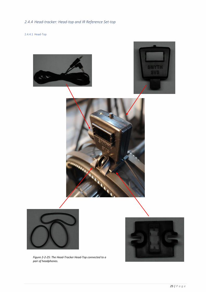
2.4.4 Head-tracker: Head-top and IR Reference Set-top
2.4.4.1 Head-Top
Figure 2-2-25: The Head-Tracker Head-Top connected to a pair of headphones.

26 | P a g e
Figure 2-26: The Headphone and head-tracker head-top connected to the Realiser via the ports in the front panel.

27 | P a g e
2.4.4.2 IR Reference Set-top
Figure 2-27: Set-Top powered up
Figure 2-28: Set-Top connected to the Realiser via the Set-top port on the rear panel.

28 | P a g e
2.4.4.3 Binaural microphones
Figure 2-29: The binaural microphones used to create a PRIR.

29 | P a g e
Figure 2-30: Binaural Microphone in ear
Figure 2-31: Binaural Microphones in use.
Figure 2-32: The Microphones connected to the Realiser
Figure 2-34: The wrist strap connected to ground.
Figure 2-33: The wrist strap worn during a binaural reading.

30 | P a g e
Quick start
1. Connect an BD or DVD player (or other HDMI source) to HDMI Input 1 and a TV monitor to the HDMI Out
2. Connect the 12V DC power supply to the A16.
3. Power up the A16, using the remote control if necessary.
The A16 will initially display a splash screen, then show presets loading, and finally display a preset Speaker Map for
User A. The audio source will automatically be set to HDMI input 1, and the default preset is for a 9.1.6ch Dolby Atmos
configured room.
4. Set the BD or DVD player (or another HDMI source) to output BITSTREAM audio to the A16, and start playing a DVD or
BD disc.
If a Dolby bitstream is detected by the A16, the Speaker Map will display Dolby Atmos as the source, and audio signals
will be visible on some of the speakers icons in the Speaker Map – the actual speakers will depend on the format of the
Dolby bitstream.
If the HDMI source is set to AUTO output, and an audio CD is played, a PCM bitstream will be detected by the A16, the
Speaker-map will display PCM as the source and will switch to the default 9.1.6ch PCM configured room. Audio signals
will be visible on only the left and right speaker icons in the Speaker-map.
Currently the A16 cannot detect or decode any DTS bitstream.
5. Set the GAIN of headphone A to L(ow) and set the headphone volume of A to 50 using either the VOL knob or the
remote control.
6. Connect headphones to the headphone output for User A and check that the volume is not excessive before putting the
headphones on.
The headphones will now be playing an SVS headphone rendered version of the decoded audio signals.
Details of all the connections on the Realiser are described in Appendix I

31 | P a g e
3 Initial power up
Power On Sequence
During power up the A16 goes through a sequence of hardware and firmware tests that are shown on the LCD display. The sequence for a successful power up is:
1. Splash screen display
2. Hardware tests
3. Loading and activating presets (or the last used presets)
4. Displaying the Speaker Map page for User A
3.1.1 Splash screen
The splash screen will be changed periodically to indicate major revisions of the firmware.
3.1.2 Hardware tests
While the splash screen is being displayed the A16 runs internal tests on the DSP memories, CPU memory, FPGAs, HDMI interface board and audio decoding module. If any of these fail the A16 will not boot correctly and an error screen will indicate the hardware fault. Any hardware fault is major and requires the unit be returned for repair.
3.1.3 Loading and running Presets
After the hardware tests have been completed successfully, the A16 will attempt to load and run (or activate) the last used presets for User A and User B. The preset for User A will be loaded and activated first, followed by the preset for User B.
If either of the two presets do not load and run successfully, the power-up sequence will stall at this point. During the next power-cycle the A16 will not attempt to load and activate the ‘invalid’ preset.
If both presets are invalid the A16 will need to be power-cycled twice, in order to bypass loading and activating the preset for both users.
A preset may become invalid due to changes that have been made to any of the underlying data and configuration files that it requires. In order to solve this issue, the Listening Rooms listed in the invalid presets should be checked for consistency and regenerated if necessary.
Figure 3-1 Splash screen on Realiser power-up.

32 | P a g e
3.1.4 Displaying the Speaker Map for User A preset
Once the presets for both users have been loaded and activated successfully, the A16 will automatically display the speaker map for the active preset for User A (Figure 3-2). The names and positions of all the speaker icons in the Speaker Map display can be found in Appendix B: Loudspeaker names and labels.
3.1.5 Listening to the Internal Audio Test Loop
From the Speaker Map page, it is possible to do a simple check of the headphone output using an internally generated musical loop signal.
1. Set the GAIN switch of headphone A output to L(ow) – the GAIN switch is located on the front panel beside the HP A socket.
2. Set the VOL of headphone A to 50 – use the VOL knob for headphone A on the front panel of the A16.
The volume can also be controlled from the remote control – the A side and B side volumes are set independently.
3. Connect headphones to the HP A socket to listen to the musical test loop.
4. Toggle ON/OFF the musical loop with the TEST key on the remote control.
The word TEST should now be displayed prominently in the Speaker Map display, and all the speaker icons should indicate some signal (Figure 3-3). Essentially a monophonic music test signal is sent to each virtual speaker and the combined signals from all the virtual speakers are sent to the headphone outputs. To listen to individual virtual loudspeakers use the L, C, R.. etc keys on the remote control to activate the SOLO mode (Figure 3-4). (The six overhead speakers are soloed using the keys 1,4,7 and 3,6,9.) A white box will outline the soloed virtual speaker on the Speaker Map display. (These virtual speakers are a factory installed default that were measured using a dummy head binaural microphone). Press the ALL key again to deactivate the SOLO mode and return to listening to all the virtual speakers. To listen to a group of virtual speakers press the ALL key to activate the MUTE mode (Figure 3-5). This mutes all the virtual speakers (muted speakers are outlined in red), and the L,C,R etc keys are then used to unmute/mute any group of speakers. Press the ALL key to deactivate the MUTE mode and return to listening to all the virtual speakers.
5. Push the TEST key again to stop the musical loop – the TEST key toggles the musical loop ON/OFF
6. Turn all the virtual speakers back on using the ALL key.
This removes the white or red boxes surrounding individual speaker icons from the display. The SOLO and MUTE modes can also be activated during normal listening modes.
The TEST, MUTE and SOLO modes are useful diagnostic tools for checking the normal operational modes of the Realiser A16.
Figure 3-2: Speaker Map of Preset 1 for User A

33 | P a g e
Figure 3-3 Test Mode: using an internally generated musical loop to listen to all the virtual speakers.
Figure 3-4 Solo Mode: listening to individual virtual speakers. The soloed speaker is outlined in white. The Centre speaker is currently being soloed.
Figure 3-5 Mute mode: listening to groups of virtual speakers. Muted speakers are outlined in red, unmuted speakers in white. The Left and Right speakers are currently un-muted.

34 | P a g e
4 Menu Navigation The Home Page menu
The Home Page is the root menu for the A16 and gives access to all functions and configuration pages of the A16 (Figure 4-1). The Home Page can be accessed from any other menu using the BACK key repeatedly.
Navigating the menus, selecting options and changing values with the remote control
4.2.1 Menu option selection:
The outer grey box indicates the menu option currently being selected, Audio Source in this example. Use the and keys on the remote control to move the selection box between different menu items.
4.2.2 Selecting values in a menu option:
The inner grey box within the menu option selector indicates that the value may be changed using the ADJ + and ADJ – keys on the remote.
Values may be numerical (a list of numbers), graphical (an on/off toggle switch) or textual (a text list or text entry).
If there are multiple variables on a line then move the selection box left and right using the and keys on the remote control.
4.2.2.1 Values from a numeric or text list:
Use the ADJ+ and ADJ- keys to select a numeric or text value from a list.
Figure 4-1: The Realiser A16 home page.
Figure 4-2: Menu option selector
Figure 4-3: Value selector within a menu option
Figure 4-4: Selecting a numeric value in a menu option

35 | P a g e
4.2.2.2 Graphical values:
Use the ADJ+ or ADJ- keys to toggle a switch ON or OFF
4.2.2.3 Text entry values: 1. Use the ENTER key to create a text-entry cursor in the value
select box.
2. Use the and keys to change the cursor from
lowercase entry (red cursor) to uppercase (green cursor).
3. To move the cursor use the and keys.
4. To delete a character use the CANCEL key.
5. Input numbers and text using the alpha-numeric keys.
6. To save the new text and exit the text box use the ENTER key.
Moving between menu levels using the ENTER and BACK keys
4.3.1 The ENTER symbol:
This symbol at the end of a menu option line indicates that pressing the ENTER command key on the remote control will either give access to another level of menus, or will start some processing, activation or updating function.
4.3.2 Menu continuation symbols: ↓ and ↑
The green ↓ and ↑ symbols, at the bottom or top of a menu
page, indicate that the visible screen is only showing part of the full menu. Use the and keys to scroll up and down between multiple pages in a menu.
4.3.3 The BACK key: The BACK key on the remote control is used to simultaneously
save configuration data and move back to either the previous
menu or to the previous page of a multi-page menu.
Figure 4-5: Value selector using an on/off toggle button
Figure 4-6: Text entry - uppercase with a green cursor
Figure 4-7: New menu or activate symbol
Figure 4-8: Menu continuation symbol for multi-page menus indicating another page below the current one.
36 | P a g e
Accessing the Preset Speaker Map page
4.4.1 The PA and PB key
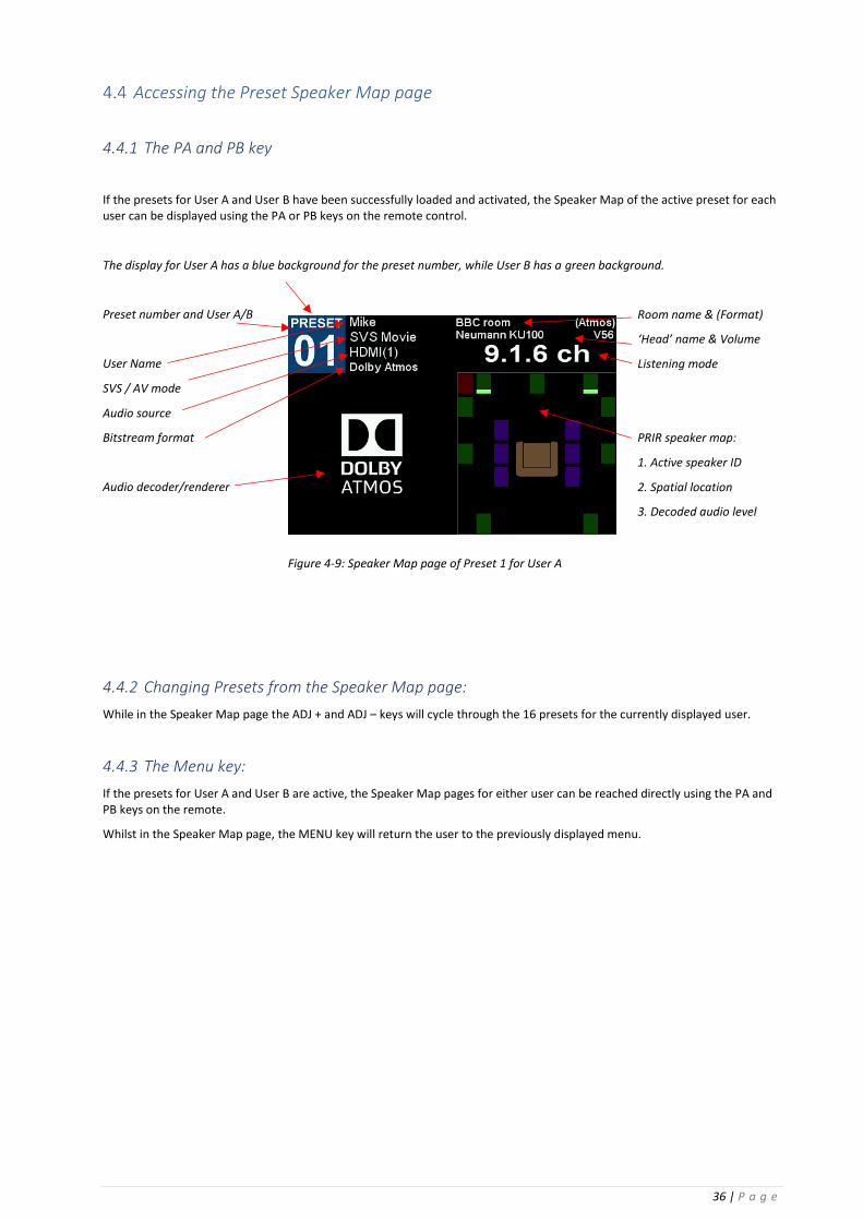
If the presets for User A and User B have been successfully loaded and activated, the Speaker Map of the active preset for each user can be displayed using the PA or PB keys on the remote control.
The display for User A has a blue background for the preset number, while User B has a green background.
Preset number and User A/B Room name & (Format)
‘Head’ name & Volume
User Name Listening mode
SVS / AV mode
Audio source
Bitstream format PRIR speaker map:
1. Active speaker ID
Audio decoder/renderer 2. Spatial location
3. Decoded audio level
4.4.2 Changing Presets from the Speaker Map page:
While in the Speaker Map page the ADJ + and ADJ – keys will cycle through the 16 presets for the currently displayed user.
4.4.3 The Menu key:
If the presets for User A and User B are active, the Speaker Map pages for either user can be reached directly using the PA and PB keys on the remote.
Whilst in the Speaker Map page, the MENU key will return the user to the previously displayed menu.
Figure 4-9: Speaker Map page of Preset 1 for User A

37 | P a g e
5 Settings The Settings menu (Figure 5-2) is accessed from the Home Page menu (Figure 5-1), and is used to set or view configuration data that seldom changes.
PRIR Sound Rooms
This option configures the A16 for measuring PRIRs. A descriptive name of the sound room can be added, a description of the format of the speaker system being measured is added, and finally all of the speakers in the room are labelled and their spatial positions are set.
Two separate rooms can be configured, and either one can be selected during the actual PRIR measurement process.
5.1.1 PRIR room 1 loc
The name of the room being measured can be added or edited. This name text will become part of the PRIR file.
Figure 5-2: Settings menu Figure 5-1: Settings option in the Home Page menu
Figure 5-3: PRIR room 1 speaker setup menu page 1
Figure 5-4: PRIR Sound Rooms menu
Figure 5-5: PRIR room 1 speaker setup page 3 Figure 5-6: PRIR room 1 speaker setup page 2

38 | P a g e
5.1.2 PRIR room 1 desc
The format of the speaker system in the room being measured can also be added or edited. The format is simply descriptive name text and becomes part of the PRIR file.
5.1.3 PRIR room 1 speaker setup
This option configures the analogue output channels of the A16 by assigning a speaker label, and other information, to each output channel number, for the purpose of making a PRIR measurement.
The information is intended to accurately describe each of the loudspeakers being measured, and this information becomes part of the PRIR file.
This menu is spread over 3 pages (Figure 5-3, Figure 5-6, and Figure 5-5).
5.1.3.1 Ch
Channels 1 to 16 refer to the physical multichannel line outputs on the back panel of the A16. These physical outputs must be connected to the amplifiers of the matching loudspeakers in the room, and cannot be re-configured.
5.1.3.2 Spkr
The ADJ+ and ADJ- keys are used to cycle through all the available speaker labels for each output channel. The actual names of these speakers, and their approximate physical location in a room, is given in Table 4 in Appendix B.
The speaker label chosen for each output channel should match the actual physical loudspeaker in the room being measured. For example, if the room is configured for Dolby Atmos then the Dolby Atmos naming conventions should be used.
Tables 1 and 2 in Appendix A: Listening Rooms Loudspeaker Configurations list the names of the loudspeakers used for Dolby Atmos and DTS:X layouts up to 16 channels. However, any names may be used for other formats, such as Ambisonics.
NOTE: Care should be taken when choosing speaker labels for a PRIR Sound Room. The use of some speaker names may restrict the ability of the measured virtual speakers to become associated with a particular format – in effect the virtual speaker in a PRIR file may become locked out of a particular format due to its name. These restrictions will only apply for bitstream and PCM audio that is input through HDMI, and are summarised in Appendix B: Table 4: Loudspeaker names and labels. For example, if a virtual speaker is labelled as Lh (Left height) it can be seen from Appendix B: Table 4 that this name is not used in any Dolby Atmos configuration that can be rendered by the Realiser A16. Therefore, a virtual speaker labelled as Lh in any PRIR file will not be matched to a decoded audio output channel when listening to any Dolby Atmos encoded bitstream. Alternatively, if a virtual speaker is labelled Ltf (Left top front) this name is used by Dolby Atmos, DTS:X and PCM, and therefore can be matched in at least one configuration of either a Dolby Atmos, DTS:X or PCM Listening Room.
5.1.3.3 Azi
This describes the azimuth angle of the loudspeaker with respect to the PRIR measurement position – normally the central listening position. Negative angles are used for left side loudspeakers, positive values for right side speakers.
5.1.3.4 Elev
This is the elevation angle of the loudspeaker, with respect to ear height, from the listening position. Positive angles are used for speakers above ear level, negative for below ear level.
5.1.3.5 Path
Path describes the distance (in metres) of each speaker from the listening position. This is not currently used in the SVS algorithm and can be left unchanged.
5.1.3.6 Gain
Gain describes the gain setting used during the SVS calibration routine. This is not currently used in the SVS algorithm and can be left unchanged.
5.1.3.7 Size
Size can be set to L(arge), for full bandwidth speakers, or S(mall) for speakers that cannot reproduce low frequencies.

39 | P a g e
5.1.3.8 UF and FF
UF refers to Up-Firing speakers designed to imitate Height or Top speakers by reflecting sound from the ceiling. The speaker name should match the spatial direction of the reflected sound – for example a speaker labelled Ltf (Left top front) and described as UF indicates that the reflected sound from this speaker appears to come from the Left top front position of the ceiling.
Each UF speaker is placed on top of an FF (Front-Firing) speaker, and the name of this matching FF speaker can be added here to more fully describe the UF speaker.
Figure 5-7 shows a room configured as 5.0.2ch. Channels 6 and 7 are Up-Firing speakers and are placed on top of the Left and Right speakers respectively. The sounds from channels 6 and 7 appear to come from the Left and Right top front positions, and so the speakers are labelled with these names.
These labels are not currently used in the SVS algorithm and can be left blank.
5.1.3.9 HPF
HPF refers to the low-frequency limitations of the speaker. This is not currently used in the SVS algorithm and can be left blank.
Headphones
This menu (Figure 5-8) allows the user to set descriptors for four different headphones using the alpha-numeric keyboard to insert text, and to adjust the level of bass signal sent to the headphone outputs. These headphone descriptors can be added to any HPEQ file measured for these headphones, allowing particular HPEQ files to be readily identified.
5.2.1 SVS Bass
This controls the level of low-frequency bass output to the headphones, from DC up to around 40Hz. The default is OFF, meaning that by default the control does not change the bass level. Some headphones are renowned for being bass-lite, and this control is intended to help alleviate this problem. This affects both User A and User B headphone outputs.
Figure 5-7: Labelling Up-Firing speakers in a PRIR room speaker setup
Figure 5-8: Headphone menu: the names of four headphones can be stored, and the amount of bass in the HP signal can be adjusted.

40 | P a g e
System
System settings are parameters that may need to be changed for different listening arrangements and conditions (Figure 5-9).
5.3.1 Assign solo buttons
During test procedures individual speakers, both real and virtual, can be soloed using a number of keys on the remote control. This menu allows the user to change the assignment using the ADJ+ and ADJ- keys on the remote (Figure 5-10).
CAUTION: Any of the solo keys can be re-assigned. Figure 5-10 illustrates the key labelled Ls on the remote control has been re-assigned to solo a Lss speaker. Therefore, after re-assignment, the actual label names on the remote-control keys may not reflect the speaker names that they control.
5.3.2 HT Settings
The Head-tracker consists of a head-top device (placed on the headphones) and a set-top device that normally sits on top of a monitor or TV, centrally.
The head-top device has three tracking elements: inertial (gyro), magnetic and optical. The inertial element is the primary means of tracking the rotation of the listener’s head, with either the magnetic or optical elements being used to stabilise the inertial tracking – i.e. to correct for inertial drift. The inertial tracker can also be used with no stabilisation.
The optical stabilisation requires a periodic pulse of IR light from the set-top device, whilst using magnetic stabilisation (or NONE) does not require the set-top device. If magnetic stabilisation is used then the set-top device simply indicates that the head-tracker is working and the approximate angle.
The optical sensor has been factory calibrated whilst the magnetic sensor should normally be calibrated in the actual listening position in the room where the A16 is being used. The magnetic sensor calibration method is described in Appendix C. Home Page menu: Apps menu: Calibrate head tracker menu: Calibrate magnetics.
Figure 5-9: System Menu
Figure 5-10: Assign solo buttons menu. In this example the Ls key has been configured to control the Lss speaker.

41 | P a g e
5.3.2.1 Stabilisation
Stabilisation refers to the method of correcting for long-term drift of the inertial tracking element in the head-tracker.
If NONE is selected then the inertial tracking operates without any reference to the magnetic or optical elements. Drift compensation acts to pull the current inertial heading to zero degrees, and can be set to either FAST or SLOW. Essentially this means that if the headphones are held static in any direction, this direction will eventually become zero degrees – i.e. the virtual centre speaker will eventually move to this direction. If MAGNETIC or OPTICAL is selected then, within the stabilisation window, the inertial reading is pulled to match the reading of the magnetic or optical elements. Outside the stabilisation window the inertial tracker operates by itself, using drift compensation to pull the current heading towards zero. If MAGNETIC is selected then the zero degrees angle must be set using the push-button switch on top of the head-tracker when looking at zero degrees. Pushing this button defines the zero-degree angle for the magnetic sensor. This should be done after the magnetic sensor has been calibrated – see Appendix C. If OPTICAL is selected then the position of the set-top IR reference indicates zero degrees. The optical sensor has already been calibrated at the factory.
5.3.2.2 Stabilisation window
This sets the window size to either WIDE or NARROW within which stabilisation operates (if a stabilisation mode has been selected). Outside the stabilisation window only the inertial sensor is used to measure the head orientation angle. Within the stabilisation window the angle measured by the magnetic or optical sensors supplements the angle measured by the inertial sensor.
NOTE: The optical tracking element can be easily fooled by IR light from regular light sources which fall outwith the stabilisation window, and this would tend to pull the zero degrees heading very quickly towards this new IR source. The magnetic sensor is not affected by external sources of light.
5.3.2.3 AB Demo mode
Normally set OFF. When set ON the tilt angle of the head-top can be used to trigger the A16 to switch between headphone and speaker outputs (AV mode). This is useful for comparing virtual and real loudspeakers immediately after a PRIR has been measured, but during normal playback this can be distracting.
5.3.2.4 Set-top display
This sets the light intensity of the green LEDs in the set-top device. It can also be set OFF. This does not affect the intensity of the IR source in the set-top used for optical stabilisation.
5.3.2.5 Drift compensation
This lets the current angle, measured by the inertial sensor, leak away exponentially to zero either in SLOW or FAST mode.
5.3.2.6 Update HT firmware
Used to update the head-tracking firmware in the head-top - the head-top must be connected to the HT port of User A.
New head-tracking firmware would normally be included within a new A16 firmware file, and would be loaded using the micro-SD card. Details on updating the HT firmware are given in Appendix I. The current head-tracking firmware version can be viewed in the Updates/About menu.
Home Page menu: Settings menu: Updates/About menu
Figure 5-11: HT Settings menu

42 | P a g e
5.3.3 Measurement Settings
This option sets parameters that may need to be changed during a PRIR or HPEQ measurement (Figure 5-12).
5.3.3.1 Max sweep Vol
Sets the maximum volume of the sine wave sweeps output from the Multichannel Line Outputs during the PRIR measurement. This will over-ride the value set in the Max Vol line option of the System menu (Home Page menu: Settings menu: System menu). In other words, during a PRIR measurement the maximum volume of the sine sweeps can be set to a higher (or lower) value than the maximum line out volume set for normal audio playback.
5.3.3.2 SVS Mic gain
Sets the gain of the binaural microphone during the PRIR and HPEQ measurements. For example, the gain may need to be increased to boost the microphone signals if the sine sweeps from the loudspeakers are too low in volume. A lower mic gain will normally increase the signal-to-noise ratio of the recorded sine sweeps, and is generally preferred.
5.3.3.3 Lock PRIRs
A locked PRIR can only be used by the A16 that was originally used to measure it.
Normally set OFF. When set ON a measured PRIR is locked to the host A16. When set OFF a measured PRIR can be used by all A16 units.
5.3.3.4 Auto save
Normally set OFF. When set ON a measured PRIR is automatically saved to the SD-card
5.3.3.5 Voice-Tone rel gain
This changes the relative loudness of the voice prompts compared to the sine sweeps during PRIR measurements. Because the voice prompts are emitted from all active speakers during a PRIR measurement whilst the sine sweeps are emitted from either one or four loudspeakers, in certain situations it is useful to be able to reduce or increase the loudness of the voice prompts. This control does not affect the loudness of the sine sweeps – only the loudness of the voice prompts.
5.3.3.6 Mic Type
Normally set to A16. The A16 and A8 binaural microphones have slightly different frequency response characteristics, and this menu option partially compensates for this difference. It does not compensate for the electrical differences between the microphones.
Caution: The A8 microphones CANNOT be used directly with the A16 and will be damaged if this is attempted. Please contact the company if you wish to connect A8 microphones to the A16.
5.3.4 Volume settings
This option sets the maximum headphone output volume for User A and User B, and also configures other volume settings.
Figure 5-12: Measurement settings menu

43 | P a g e
5.3.4.1 Max Vol A & Max Vol B
These set the maximum headphone output volume for User A and User B.
5.3.4.2 HPB->A
This option, when enabled, allows the headphone output for User B to be switched almost instantaneously to the headphone output of User A. This can be very useful when comparing small variations in either PRIR measurements or HPEQ adjustments. This mode is only available when in the Preset Speaker Map display. Further details on this feature are given in section 7.4.2.10.
5.3.4.3 Max Vol line
Sets the maximum Multichannel Line Output volume for audio playback during AV playback mode or during A/B switching mode. This does not affect the volume of the sine-wave sweeps output during a synchronous PRIR measurement which are set by the Max Sweep Vol set in the Measurement Settings menu
Home Page menu: Settings menu: Measurement Settings menu: Max Sweep Vol option
5.3.4.4 Tri-vol
This option, when enabled, sets the Tri-volume option for User A headphone output using the rocker-switch volume control for User A on the remote control. Details of this option are described in Appendix N: Tri-volume headphone output.
5.3.5 LCD off timer
This option, when enabled, turns off the back-light of the LCD display of the A16 after a configurable number of minutes (5 mins to 30 mins). The timing begins (and is re-set) from the last user command received. Any command from the remote control or the front-panel volume knobs turns the display back on.
5.3.6 Default HDMI input
HDMI audio signals are physically linked to their corresponding video signal and therefore, when an HDMI audio source is selected the correct video source is automatically switched to the HDMI output and is seen on the video monitor.
This is not the case for non-HDMI audio signals, and this menu allows a linkage to be created for the purpose of switching the correct HDMI video signal to the HDMI output. An example is shown in Figure 5-13.
Figure 5-14: Default HDMI input menu: linking non-HDMI audio input sources to HDMI inputs for the purpose of switching and viewing the correct video signal
Figure 5-13 Volume settings menu

44 | P a g e
5.3.6.1 Source
All non-HDMI audio sources are listed, and each can be given a different assignment.
5.3.6.2 HDMI input
Each source should be allocated an HDMI input. The default assignment is HDMI 1.
5.3.6.3 Audio bypass
When enabled, this switches the HDMI audio signal as well as the HDMI video signal.
5.3.7 Full factory restore
When enabled, this will restore the A16 to the factory default settings. This includes all the configuration data, all the Listening Rooms and all Presets for both users. It also erases any PRIR and HPEQ measurement data from the circular memory buffers. However, PRIR and HPEQ files in permanent memory are not erased.
CAUTION: This command may permanently erase important PRIR and HPEQ measurement data and other settings.
5.3.8 Factory Tests
When enabled, this menu option provides access to a range of audio tests for confirming the correct operation of the A16. These tests are more fully explained in Appendix O: Factory Tests.
CAUTION: These tests output full range analogue and digital signals which can damage hearing and audio equipment.
Time
Used to set the date and time using the ADJ+ and ADJ- keys (Figure 5-14). The current date and time are also added to PRIR and HPEQ measurements for identification purposes.
NOTE: The ENTER key must be used after each line entry to force the date/time value to be updated
Users
Eight different user names can be added using the alpha-numeric keyboard to insert text. These names are then added to measured PRIR and HPEQ files allowing these files to be more easily identified. These names are also used to save and select presets.
Figure 5-15: Time menu: setting the current date and time

45 | P a g e
Updates/About
Provides information on the version numbers of the firmware running in the A16. It also shows the serial number of the host Realiser A16.
5.6.1 Check for updates at power-up
Normally set OFF.
When set ON the unit will scan the SD card and the internal permanent memory for any new firmware revisions that may have been downloaded previously, and will update each programmable part if a newer version is detected.
NOTE: Full details for updating the A16 with new firmware are given in Appendix G: Updating the Realiser A16 Firmware.
5.6.2 Generate log file
This generates a small 1 kbyte file and writes it to the Realiser folder of an SD-card. The log file consists of information that uniquely identifies the A16, such as the serial number, and can be used to create an account on the Realiser Exchange website – check website for details.
Restore factory setup
This option returns some of the core A16 settings to the factory default condition. It is intended to allow users to get the system working again. It uses pre-installed factory default PRIRs and HPEQ files to generate default Listening Rooms, and then creates default Presets based on these Listening rooms.
This function also erases PRIR and HPEQ files in the recycle buffers, overwrites Listening Rooms 1 to 4, and overwrites Presets 1 to 4. Therefore, users should save important PRIR and HPEQ files to SD card, or to memory locations that will not be over-written, before proceeding.
Figure 5-16: Users menu: the names of eight users can be stored
Figure 5-17: Updates/About menu

46 | P a g e
Figure 5-18: Restore factory setup menu: Warning message

47 | P a g e
6 File Management
Files menu
On the Home Page menu, the file menu is accessed through the Files option.
Home Page menu: Files menu
Memory locations
Permanent internal storage for PRIR and HPEQ files. Files can be moved into permanent memory from the recycle buffer or micro-SD card. Files can also be deleted from permanent memory.
External micro-SD card storage for PRIR and HPEQ files. Files can be copied to/from the SD card from/to the permanent internal memory. Files cannot be deleted from the micro-SD card.
Internal recycle buffer used for storing measured PRIR and HPEQ files. There are sixteen (16) slots in the buffer, and the last saved measurement is always stored in slot 1. Measured PRIR and HPEQ files must be moved to permanent internal storage to avoid being over-written. Files can be copied from the recycle buffer to permanent
internal storage and to the micro-SD card. Files cannot be deleted from the recycle buffer, but will eventually be over-written once the buffer is filled.
Factory installed PRIR and HPEQ files. These files cannot be copied, deleted or modified. In the event that the firmware of the A16 unit must be reset, these PRIR and HPEQ files are used to re-create factory-default listening rooms for Dolby Atmos, DTS:X and PCM formats.
PRIR files menu
Home Page menu: Files menu: PRIR files menu
The PRIR files menus for all four memory locations are similar, but differ in the options for moving or deleting the files.
Figure 6-1 File menu showing the number of PRIR and HPEQ files in each location.

48 | P a g e
6.3.1 Location
This is the name of the room where the PRIR was measured. If a photograph of the room is attached to the PRIR it can be viewed using the ENTER key.
6.3.2 Layout, Subject, Date
Information relating to the PRIR measurement to assist in identifying a given PRIR.
6.3.3 Copy to SD card menu and Delete menu
PRIR files may be copied from permanent storage or the recycle buffer to an external SD card (when available). PRIR files may also be deleted from permanent storage – but cannot be deleted from the external micro-SD card or the recycle buffer.
Figure 6-4 Image of the room in which the PRIR was measured.
Figure 6-5 Copying a PRIR file from permanent memory to an SD-card
Figure 6-3 Image of the room in which the PRIR was measured.
Figure 6-2 Selecting a PRIR file from permanent storage.
Figure 6-6 Deleting a PRIR file from permanent memory.

49 | P a g e
HPEQ files menu
Home Page menu: Files menu: HPEQ files menu
The HPEQ files menus for all four memory locations are similar, but differ in the options for moving or deleting the files.
6.4.1 Phones, Subject, Time
Information relating to the HPEQ measurement to assist in identifying a particular HPEQ file.
6.4.2 Content
This describes the EQ information available in the HPEQ file. Currently there are four sets of data, one set (autoEQ) taken with the automatic HPEQ measurement procedure, one set (flatEQ) generated at the same time as the autoEQ, and two optional sets that are typically manual adjustments to the autoEQ or flatEQ data. The flatEQ filter was designed to be used as the base filter for IEM-type headphones.
autoEQ: All HPEQ files contain autoEQ data, measured using the automated EQ procedure. flatEQ: This EQ filter is flat and is typically used as the base filter for IEM-type headphones. manLOUD: Manual EQ adjustments determined using the Equal Loudness EQ measurement procedure. manSPKR: Manual EQ adjustments determined using the External Speaker EQ measurement procedure.
6.4.3 Copy to SD card menu and Delete menu
HPEQ files may be copied from permanent storage or the recycle buffer to an external SD card (when available) Figure 6-10. PRIR files may also be deleted from permanent storage (Figure 6-9) – but cannot be deleted from the external micro-SD card or the recycle buffer. Use a computer to delete files from a micro-SD card.
Figure 6-7: HPEQ files menu
Figure 6-8 A HPEQ file in the recycle buffer showing three filters, autoEQ, manLOUD and manSPKR. Any of these filters can be chosen as the HPEQ filter within a preset.

50 | P a g e
Figure 6-9: Deleting a HPEQ file from permanent memory
Figure 6-10: Copying a HPEQ file from permanent memory to an external SD-card

51 | P a g e
7 Configuring a Preset for SVS headphone or AV mode
The primary purpose of a Preset is to select personalised Listening Rooms and Headphone EQ filters for an individual listener.
Presets bring together Listening Rooms (which contain PRIR data), configuration data and user information, and are the gateway for running the headphone virtualisation process of the A16.
Presets contain Listening Rooms for each of the major listening formats (Dolby Atmos, DTS:X and PCM), and can automatically switch between these rooms when the incoming bitstream changes.
The selected Listening Rooms also configure the rendering /listening mode of the bitstream decoder. For example, one Preset may select to decode and render Dolby Atmos in a room with a 9.1.4ch configuration, and to decode DTS:X in a different room with a 7.2.4ch configuration. The A16 will then automatically switch between these different configurations if the bitstream changes.
The loudspeaker configuration of a room may also be called the Listening Mode in this manual.
NOTE 1: Presets are configured and stored independently for each user, A and B. However, the design of the A16 requires that the same Listening Mode be operating for both users A and B, and this is set from the Preset for User A. For example, if the current Preset for User A demands a 7.1.4ch listening mode, while the current Preset for User B is requesting a 2.0ch listening mode, the active Listening Mode will be set to 7.1.4ch but User B will only process and render 2.0ch of the full 7.1.4ch mode. NOTE 2: For the correct operation of the A16 it is vital that Presets for both User A and User B are loaded and active, since much of the real-time functionality of the A16 (e.g. head-tracking) requires that both DSPs are running correctly.
The Home Page Menu
The Home Page Menu is the starting point for navigation through the menus, and provides access to all functions and features of the Realiser A16.
NOTE: User A and User B run on separate DSP processors and therefore the presets for A and B must be configured, loaded and activated independently. The total number of different presets that can be stored is 256. This number comes from: 2 (User A and B) x 8 (User names) x 16 (presets per user name) = 256 presets.
1. Select which User Preset to configure – choose User A or User B using the UP and DOWN arrow keys 2. Select the User Name for the preset using the ADJ+ and ADJ- keys
New user names are entered in the Users menu (Home Menu → Settings → Users)
3. Move to the Preset Menu page using the ENTER key
Figure 7-1: The Home Menu page with the User Presets highlighted

52 | P a g e
The Preset Menu
The Preset configuration menu for User A is spread over two pages (Figure 7-3 and Figure 7-2), while the configuration menu for user B has fewer options and is contained within one page (Figure 7-4). Presets allow individual users to choose their preferred listening room for different audio bitstreams, and allows the configuration of these listening rooms to be modified. For example, a single user could configure two presets to have the same listening rooms for Dolby and DTS bitstreams, but configure each preset to use a different upmixer when rendering PCM audio streams.
The Preset menu is also used to select a personalised Headphone EQ measurement for an individual listener.
7.2.1 Select the Preset number
For each user name sixteen different presets can be configured and saved internally. The factory default initially stores the same 16 presets for Users 1 thru 8 for both listener A and B.
Use the ADJ+ and ADJ- keys to select an individual preset, for activating or to change the configuration of the preset.
The ENTER key loads and activates the selected Preset. Once the preset is active the PA key will show the Preset Speaker Map page for User A (blue background to the preset number, Figure 7-6) and the PB key will show the Speaker Map page for User B (green background, Figure 7-5)
Figure 7-2: User A Preset Menu page 2 Figure 7-3: User A Preset Menu page 1
Figure 7-5: Preset Speaker Map for User B Figure 7-6: Preset Speaker Map for User A
Figure 7-4 User B Preset Menu page
53 | P a g e
7.2.2 Set the SVS Rendering Mode
The Mode selector for the Preset is currently fixed to SVS Movie mode. Other modes may be available in future firmware versions.
7.2.3 Verify the User
The User name is informational only. It is selected in the previous menu (Home Menu page) by hovering the cursor over the preset option and using ADJ+ and ADJ- buttons to select a user.
7.2.4 Select the Atmos, DTS:X and PCM listening rooms for this preset number
These are the Listening Rooms that have been previously created for each bitstream format. Up to 32 different listening rooms in each format are available for selection in a Preset.
For example, Figure 7-3 shows that User A, Mike, has configured Preset 1 to use Atmos Listening Room #1, DTS:X Listening Room #2 and PCM Listening Room #4. These listening rooms have been created from dummy head measurements (Neumann KU100), but would more typically be created from room impulse response data (PRIR data) personalised to the user Mike.
7.2.5 Toggle the AV mode ON or OFF
Normally set OFF.
When set OFF this Preset, when active, will not allow audio to be output to the 16-ch line outputs, and can only be used for SVS headphone rendering of decoded audio.
When set ON this Preset, when active, allows decoded audio to be output to either the 16-ch line outputs or to be rendered to the SVS headphone outputs. In AV mode the A16 is being used as an AV receiver and the decoded audio signals are routed directly from the phono outputs to loudspeaker amplifiers.
When the AV mode is enabled for a preset the loudspeaker icon and headphone icon keys on the A16 remote-control are used to toggle between the AV loudspeaker mode and SVS headphone mode.
7.2.6 HPEQ menu
The HPEQ file is intended to store the impulse response data of a particular pair of headphones calibrated for an individual user, often using binaural microphones mounted in the user’s ear canals. The HPEQ file will typically contain inverse filter coefficients generated automatically from the measured impulse response data (autoEQ), and may also contain a flatEQ filter and filters generated manually (manLOUD and manSPKR). In addition, the HPEQ file contains identifying information such as the subject’s name, the model name of the headphones and the time/date of the HPEQ measurement.
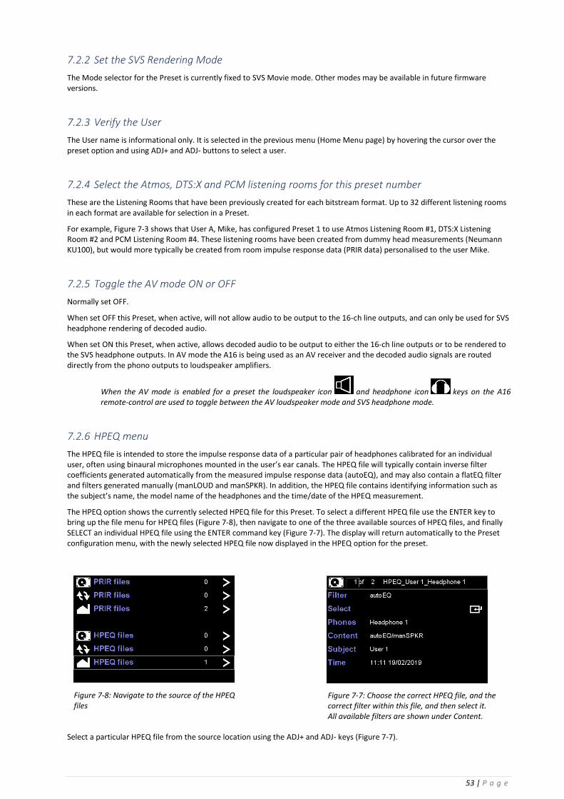
The HPEQ option shows the currently selected HPEQ file for this Preset. To select a different HPEQ file use the ENTER key to bring up the file menu for HPEQ files (Figure 7-8), then navigate to one of the three available sources of HPEQ files, and finally SELECT an individual HPEQ file using the ENTER command key (Figure 7-7). The display will return automatically to the Preset configuration menu, with the newly selected HPEQ file now displayed in the HPEQ option for the preset.
Select a particular HPEQ file from the source location using the ADJ+ and ADJ- keys (Figure 7-7).
Figure 7-7: Choose the correct HPEQ file, and the correct filter within this file, and then select it. All available filters are shown under Content.
Figure 7-8: Navigate to the source of the HPEQ files

54 | P a g e
7.2.6.1 Filter
Select the required inverse filter; autoEQ, flatEQ, manLOUD or manSPKR (if available). All available filters within the HPEQ file are shown in the Content line. AutoEQ will always be available as a filter option.
7.2.6.2 Select
Finally, use the ENTER key to select this HPEQ inverse filter into the preset. The display will automatically revert back to the preset configuration page.
7.2.6.3 Phones, Subject, Time
Descriptive information about the measured headphones, the measured subject and the date and time of the measurement. These are all set during the actual HPEQ measurement.
7.2.6.4 Content
Displays the valid inverse filters contained within the measured HPEQ file. AutoEQ will always be displayed and available as an option, whilst the two manual EQ filters (manLOUD and manSPKR) will only be displayed if they are available.
The manual EQ filters are normally based on the automatically generated HPEQ autoEQ filter or flatEQ filter and details of how these are generated are found in Chapter 10: Measuring personalised HPEQ.
NOTE: A valid HPEQ file must be ALWAYS be selected for User A and User B for SVS headphone rendering. The factory default HPEQ files can always be used.
7.2.7 PCM Audio management
PCM Audio management is an option found on the second page of the Preset configuration page for User A (Figure 7-2). This option leads to the PCM Audio Management menu (Figure 7-9) and configures the A16 to optionally either up-mix or pass-thru PCM audio signals from the HDMI or SPDIF inputs. For all other input types the upmixer option is not available.
Digital PCM signals from any of the HDMI inputs can be mono, stereo or multichannel, while digital PCM signals from the SPDIF inputs (co-axial or optical) are limited to mono or stereo.
For each of these inputs the user can select to either use the direct (or unmodified) digital PCM signal, whether mono, stereo or multichannel, or can use an upmixer. Either Dolby Surround or DTS Neural:X upmixers can be selected as the upmixer for either source.
The BACK key saves these settings are moves back to the previous preset configuration menu.
Note: this is only selecting the upmixer for PCM signals – not for bitstream audio data.
7.2.8 Legacy Dolby decode
When set ON, this disables the Dolby Atmos decoder from outputting signals to any height loudspeakers, real or virtual. This is intended for users who have a legacy speaker layout, such as stereo, 5.1ch or 7.1ch, and who do not have any height speakers.
When set OFF, this instructs the Dolby Atmos decoder to operate normally.
Figure 7-9: PCM Audio Management Menu: selecting the upmixer for PCM audio sourced from HDMI and SPDIF inputs

55 | P a g e
7.2.9 Legacy DTS decode
When set ON, this disables the DTS:X decoder from outputting signals to any height loudspeakers, real or virtual. This is intended for users who have a legacy speaker layout, such as stereo, 5.1ch or 7.1ch, and who do not have any height speakers.
When set OFF, this instructs the DTS:X decoder to operate normally.
7.2.10 Dolby night mode
This option limits the dynamic range of the decoded Dolby Atmos output signals, and can be set ON, OFF or Auto.
7.2.11 DTS night mode
This option limits the dynamic range of the decoded DTS:X output signals, and can be set ON or OFF.
7.2.12 Dolby Surround
When enabled, this instructs the Dolby Atmos decoder to upmix, using Dolby Surround, any decoded legacy Dolby bitstreams to the selected listening mode for this preset, for any detected Dolby bitstream.
When disabled, this instructs the Dolby Atmos decoder NOT to upmix any legacy Dolby bitstreams.
7.2.13 DTS Neural:X
When enabled, this instructs the DTS:X decoder to upmix, using DTS Neural:X, any decoded legacy DTS bitstreams to the selected listening mode for this preset, for any detected DTS bitstream.
When disabled, this instructs the DTS:X decoder NOT to upmix any legacy DTS bitstreams.
Note: To save the complete preset configuration move BACK to the main preset configuration page and then move BACK to the Home Menu Page. The Preset configuration will be saved but will not be loaded or activated.
Load and Activate presets for User A and User B
1. Select the audio source: In the Home Page menu navigate to the Audio Source option, and use the ADJ+ and ADJ- keys to select the audio source.
2. Select a user name for Preset A, then load and activate the Preset a. In the Home Page menu navigate to the Presets menu option for User A, then use the ADJ+ and ADJ- keys to
select a user name for Preset A. b. Press ENTER to move to the Preset Configuration menu. c. Scroll through the available Presets for this user name using the ADJ+ or ADJ- keys. d. To load a selected Preset use the ENTER key. A short “Loading” message will be displayed in the top line
during this operation, followed by a short “Active” message to indicate that the Preset is now running. 3. Navigate BACK to the Home Page, select a user name for Preset B, then load and activate the Preset
a. In the Home Page menu navigate to the Presets menu option for User B, then use the ADJ+ and ADJ- keys to select a user name for Preset B.
b. Press ENTER to move to the Preset Configuration menu. c. Scroll through the available Presets for this user name using the ADJ+ or ADJ- keys. d. To load a selected Preset use the ENTER key. A short “Loading” message will be displayed in the top line
during this operation, followed by a short “Active” message to indicate that the Preset is now running. 4. Display the Speaker Map for the active Presets for User A or User B
a. Once a Preset is loaded and activated the Preset Speaker Map for either User A or User B can be displayed using the PA or PB keys (Preset A or Preset B) on the remote control. Figure 7-11 shows the rendering for Preset 1 for User A.
b. The ADJ+ and ADJ- keys scroll up and down through the 16 presets for each user. (Note: it takes a few seconds to load each new preset.)

56 | P a g e
The background colour around the Preset number indicates that the preset is either for User A (blue) or User B (green).
In the graphic panel each speaker icon also displays the decoded signal level for that speaker, whether in AV loudspeaker mode or SVS headphone mode.
Information relating to the names of the speakers displayed in the graphic panel can be found in Appendix B: Graphical representation of loudspeakers in the Speaker Map display of the A16.
Note: The Preset Speaker Map shows the current ACTIVE preset for users A and B. When a preset is selected in the Preset Menu, a copy of the preset is loaded into the DSP and activated. Therefore, it is possible to return to the Preset Menu and change some parameters of the original preset, without changing the active preset. The changes will only take effect when the modified preset is loaded and activated. If changes are made in the currently active preset the user is prompted to RELOAD the preset.
Note: Changes to a preset involving operation of the headtracker (and some other real-time parameters) will take effect instantly, without needing to reload the preset.
Audio Meters
Move to: Home Page menu: Audio Meters (user A or user B)
The audio meters display shows the level of all the audio signals entering the A16 headphone rendering DSP, and the level of the headphone and tactile signals being output from the same DSP. Either user A or B can be selected for display, but the actual listening mode is set by user A.
The speaker names are taken from the currently active preset (either A or B). The levels shown are identical in value to those displayed in each speaker icon in the Speaker Map display. Clipping on the input and output is also indicated and is reset using the red CANCEL key on the remote control.
7.4.1 Elements of the Speaker Map display for any preset (Figure 7-11)
1. Preset number and user A (blue background) or B (green background)
2. User name
3. Rendering mode – either SVS Movie mode for headphones or AV mode for loudspeakers
4. The audio source – either HDMI (1,2,3 or 4), USB, Line, Stereo, Co-axial or Optical
5. The audio type – either none (no audio detected), bitstream (Dolby or DTS) or PCM (PCM, PCM 2ch, PCM 6ch or PCM 8ch)
6. The audio decoding/rendering mode – either Dolby Atmos, Dolby Audio, DTS:X, DTS Neural:X or PCM
7. The Listening Room name – this refers to the PRIR data (Ch-1) that was used to create this listening room.
8. The Subject name – this refers to the PRIR data (Ch-1) that was used to create this listening room.
9. The Listening Mode – valid listening modes for each format are listed in the Appendix
10. A visual representation of the speakers in the Listening Room – further details are listed in Appendix B
Figure 7-10 Audio Meter display showing the level of the 16 channels entering the A16 headphone rendering DSP and the headphone and tactile output levels.

57 | P a g e
1. Preset number and User A/B 7. Room name & (Format)
8. Subject name & Volume
2. User Name 9. Listening Mode
3. SVS Movie / AV mode
4. Audio source
5. Bitstream format 10. Speaker map
i. Active speaker ID
6. Audio decoder/renderer ii. Spatial location
iii. Decoded audio level
NOTE: The ADJ+ and ADJ- keys scroll up and down through the 16 presets for each user. It takes a few seconds to load each new preset.
7.4.2 Controls associated with the Speaker Map display
7.4.2.1 Headphone volume control in SVS Movie mode
The volume of the headphone output is controlled via dedicated volume control rocker keys on the remote control or via the physical volume knobs on the front panel of the A16.
The volume control changes the headphone output when the A16 is operating in SVS Movie mode.
When operating in AV mode the volume control changes the level of the analogue line outputs which would typically be connected to loudspeaker amplifiers.
The volume is displayed momentarily on the LCD display (Figure 7-12 and Figure 7-13). Both User A and B can set their headphone volumes independently. In SVS Movie mode changing the volume for either user also changes the Speaker Map display to show the active preset for that user.
The headphone outputs of User A and User B can be muted independently using the MUTE toggle keys.
7.4.2.2 Line output volume control in AV mode
In AV mode the volume control sets the level of the multichannel analogue output signals that are fed to the loudspeaker amplifiers (Figure 7-15).
Note: In AV Mode only the Speaker Map for User A is displayed – the PB key is not valid – and the line output volume can only be controlled using the user A volume rocker switch or the User A volume knob.
Figure 7-11: Speaker Map display of Preset 1 for User A
Figure 7-12: Volume for User B headphone output
Figure 7-13: Volume for User A headphone output

58 | P a g e
7.4.2.3 Mute outputs
Muting the audio output is toggled ON and OFF by the MUTE keys on the remote control (Figure 7-14).
The headphone outputs for User A and User B can be muted independently using the MUTE-A and MUTE-B keys.
The line output level is muted using either key.
7.4.2.4 Switch between SVS Movie (headphone) mode and AV (loudspeaker) mode
To engage the AV (loudspeaker) mode use the speaker icon key on the remote control. To return to SVS Movie
(headphone) mode use the SVS headphone icon key on the remote.
In SVS Movie mode the audio is rendered to headphones as virtual loudspeakers. This is the default mode of operation
when a preset is loaded and active, and can be engaged using the SVS headphone icon key on the remote.
In AV mode the audio is intended to be rendered to real loudspeakers and is sent directly to the multi-channel line outputs. SVS headphone rendering is switched off.
NOTE: AV mode can only be engaged if AV mode has been enabled in the active preset configuration for user A. If AV mode cannot be engaged then the active preset will need to be reconfigured, saved and then re-loaded.
Move to: Home Page menu: Preset User A/B menu: AV mode option
7.4.2.5 Display head-tracking angles (Figure 7-16)
In the Preset Speaker Map display, the current values of the head-trackers for user A and B can be toggled ON and OFF using the HT key. The top value is for user A and the bottom value is for user B.
Press the HT key again to return to the Speaker Map display.
Figure 7-15: Muting the headphone output for User A using the MUTE key on the remote
Figure 7-14: Line output volume in AV loudspeaker mode
Figure 7-16: Current head-tracker angles in degrees for user A (top value) and B (bottom value)

59 | P a g e
NOTE: If the head-tracking values do not change as the headphones are moved it means that the headtracking is either not plugged in or is not working correctly.
NOTE: Headtracking is only active if presets for user A and user B are loaded and active.
7.4.2.6 SOLO Mode: solo individual speakers in SVS Movie (headphone) or AV (loudspeaker) modes
Whilst in the Speaker Map display individual loudspeakers can be soloed, using the individual speaker keys and the alpha-numeric keys on the remote to solo individual speakers.
When in the Speaker Map display to SOLO a speaker simply push the key assigned to that speaker. A white box is placed around the speaker icon in the speaker map (Figure 7-18). Only one speaker at a time can soloed. To disengage the SOLO mode and listen to all the active speakers press the ALL key on the remote.
The Assign solo buttons menu is used to change the solo speaker key mapping on the remote control. Any speaker label can be assigned to any of the available keys. (Home Page: Settings: System: Assign solo buttons)
7.4.2.7 MUTE mode: mute individual speakers in SVS Movie (headphone) or AV (loudspeaker) modes
Whilst in the Speaker Map display groups of loudspeakers can be muted, using the individual speaker keys and the alpha-numeric keys on the remote to select/de-select individual speakers.
When in the Speaker Map display to enable MUTE mode press the ALL key. A red box is placed around all the muted speaker icons in the speaker map (Figure 7-17). To toggle mute ON or OFF for an individual speaker use the solo speaker keys. All speakers can be muted or un-muted. To disengage the MUTE mode and listen to all the active speakers again press the ALL key on the remote.
NOTE: To change the solo speaker key assignment, navigate to the Assign solo buttons menu:
Home Page menu: Settings menu: System menu: Assign solo buttons menu
7.4.2.8 TEST mode: play an internal music loop
The TEST key on the remote toggles ON or OFF the playing of an internally generated musical test signal, as a continuous loop, through all active loudspeakers. In the speaker map each loudspeaker icon will show a varying level as the test signal is played. The audio test signal will play in both rendering modes – SVS Movie (headphone) and AV (loudspeakers).
While in TEST mode individual speakers can be soloed or muted using the appropriate keys on the remote control. A soloed speaker is indicated by a white border around the speaker icon, and a muted speaker is indicated with a red box. For example, in Figure 7-19 the centre speaker is being soloed.
To turn OFF the SOLO or MUTE modes and listen to ALL the speakers use the ALL key on the remote control.
To turn OFF the TEST mode and return to normal operation press the TEST key.
Figure 7-17: Muting all virtual speakers except for Left and Right speakers.
Figure 7-18: Soloing the Centre virtual speaker while listening over headphones

60 | P a g e
7.4.2.9 Increment or decrement the Preset Number
While in the Speaker Map display the preset number for user A or B can be changed using the ADJ+ and ADJ- keys to increment or decrement through the list of 16 presets allocated to the currrent named user. This operation takes a few seconds to complete while the new preset is being loaded.
NOTE: Changing the Preset Number does not change the audio source.
7.4.2.10 Re-route Headphone B signal to Headphone A output (HPB->A)
When enabled, and while in the Speaker Map display, the headphone signal for User B can be re-routed (switched) to the headphone output of User A by pressing the RIGHT ARROW icon key on the remote control (Figure 7-21).
To switch back to the normal headphone routing press the LEFT ARROW icon key or navigate away from the Preset Speaker Map display (Figure 7-20).
The HPB→A mode, while enabled, also correctly switches the headtracking input signal from User A to User B.
The main purpose of this mode is to allow two presets to be compared almost instantly in an A/B type comparison. This is possible because the presets for user A and user B are both active simultaneously and are rendering the headphone audio independently.
An alternative method of comparison is to change User A or User B presets (as outlined in section 7.4.1): however, this requires that a new preset be loaded, which takes a few seconds, making an A/B comparison more difficult.
The HPB→A option must be enabled in the System menu.
Move to: Home Page menu: Settings menu: System menu: HPB→A option
NOTE: This mode is only valid when the listener is connected to headphone A output.
NOTE: Headphone A output is NOT simultaneously switched to Headphone B output.
NOTE: The Listening Mode is set by the User A preset, even after re-routing HPB to HPA output.
NOTE: The volume for Headphone B is set using the volume rocker switch for User B.
NOTE: If the A/B demo mode is also engaged while in HPB->HPA mode, the system returns in HPA->HPA mode.
Figure 7-19: Soloing the Centre virtual speaker over headphones while listening to a looped jingle in Test mode

61 | P a g e
7.4.2.11 A/B demo mode
When enabled, and while in the Speaker Map display, the decoded audio signals can be switched from the SVS Headphone (Figure 7-23) to AV line outputs (Figure 7-22), using the tilt of the Head-top as the A/B switch. This mode does not require that the AV mode in the preset be enabled. When the Head-top is vertical the SVS headphone mode is active, and when the Head-top is tilted forwards the AV mode is active – this facilitates an individual user using their headphones to conduct an A/B listening test between the SVS virtual speakers rendered through headphones and the real loudspeakers in a room.
An alternative switching mechanism is to enable AV mode in the active preset and use the SVS headphone icon key and
AV speaker icon key on the remote control for switching.
Figure 7-20: Reverting back to the normal listening mode using the LEFT arrow key
Figure 7-21: HP B to A mode: allows an A/B comparison to be made between two presets
Figure 7-23 The normal SVS headphone mode. Figure 7-22 AV mode engaged using the A/B switch activated by the Head-top tilt detector.

62 | P a g e
8 Measuring a new PRIR in a sound room using the synchronous (ALL) method
There are two methods for measuring PRIRs – the Synchronous (ALL) method and the Asynchronous (ASYNC) method. Choosing which method to use will often depend on how easily the A16 can be connected to loudspeaker amplifiers in the listening room that is being measured.
Method 1: Synchronous (ALL) – described in this chapter
In the synchronous (ALL) method the A16 generates the sine wave sweeps that are used to measure the individual loudspeakers. These sweeps are output from the 16-ch analogue output connectors and requires that the A16 be connected directly to the loudspeaker amplifiers.
This method is described as synchronous since the number of audio samples recorded through the binaural microphones exactly matches the number of audio samples generated within the A16 – the generator and recorder are sample-rate locked.
Method 2: Asynchronous (Async) – described in Appendix F
In the asynchronous method the A16 does not generate the sine wave sweeps, and therefore the A16 does not need to be connected to the loudspeaker amplifiers. Instead the sweep signals are pre-recorded and played back through the loudspeakers in the listening room.
There are two main types of pre-recorded sweep signals, bitstream and PCM. Bitstream test signals are used in consumer sound rooms where the loudspeakers are connected to an AV receiver capable of decoding Dolby Atmos bitstreams delivered via a DVD/BD player, or other source of bitstream audio. PCM test signals are used in professional sound rooms where the loudspeakers are connected to an audio editing workstation, or some other source of PCM audio signals.
This method is described as asynchronous since the number of audio samples recorded may not match the number of audio samples in the pre-recorded audio test signals – the generator and recorder are not sample-rate locked.
Choosing the Sync (ALL) or Async method
The choice of PRIR measurement method will usually depend on whether or not the A16 can be readily connected to the loudspeaker amplifiers in the sound room. Another important consideration is that the Sync (ALL) method allows the A16 to automatically bypass the SVS headphone rendering algorithm, using the tilt detector in the headphone-mounted head-tracker. This permits the user to easily A/B compare the measured virtual loudspeakers, rendered over the headphones, with the real loudspeakers in the listening room. With the Async method this switching (if required) must be done external to the A16.
Configure the PRIR Sound room
Move to: Home Page menu: Settings menu: PRIR Sound Rooms menu: (Figure 8-1)
PRIRs are measured using real loudspeakers in a real sound room, and the PRIR Sound Rooms menu allows configuration of the A16 for measuring PRIRs. The main part of the configuration process involves describing all of the loudspeakers being measured. This includes naming (or labelling) each speaker, setting its spatial position, and setting its size. A descriptive name of the sound room, and the overall format of the speaker arrangement in the room, should also be added.
Two separate rooms can be configured, and either one can be selected during the actual PRIR measurement process.
Figure 8-1: PRIR Sound Rooms menu.

63 | P a g e
8.1.1 Edit the PRIR room 1 location (loc)
The name (or location) of the room being measured can be changed or edited. This name will become part of the PRIR file and used to identify the PRIR.
8.1.2 Edit the PRIR room 1 description (desc)
The description of the speaker format in the room being measured can also be edited. The name of the format also becomes part of the PRIR file and used to identify the PRIR.
Tables 1, 2 and 3 in Appendix A list the format names (Modes) used informally for some standard arrangements of Dolby Atmos, DTS:X and PCM rooms, but other descriptions may be more accurate for non-standard arrangements of loudspeakers – for example Ambisonics.
8.1.3 Configure the PRIR room 1 speaker setup
Move to: Home Page menu: Settings menu: PRIR Sound Rooms menu: PRIR room 1 speaker setup menu
This option moves to a new menu that configures the analogue output channels of the A16 by assigning a speaker label, and other information, to each output channel number, for the purpose of making a PRIR measurement (Figure 8-2). The information is intended to accurately describe each of the loudspeakers being measured in the room, and this information becomes part of the PRIR file.
8.1.3.1 Ch
Channels 1 to 16 refer to the multichannel line outputs on the back panel of the Realiser A16.
8.1.3.2 Spkr
All the speaker labels that can be used are listed in Table 4 in Appendix B. Each channel that is being measured should be labelled with an appropriate speaker label.
Care should be taken when choosing speaker names (labels). The use of some speaker names in a PRIR may limit the ability of the virtual speakers to become associated with a particular format – in effect the virtual speaker in a PRIR may become locked out of a particular format due to its name. These restrictions only apply for bitstream and PCM audio that is input through HDMI, and are listed in Table 4 in Appendix B.
For example, if a virtual speaker is labelled as Lh (Left height) it can be seen from Table 1 Appendix A, that this name is not used in any Dolby Atmos listening mode that the Realiser A16 is capable of rendering. Therefore a virtual speaker labelled as Lh in any PRIR file cannot be matched to a speaker in any configuration of a Dolby Atmos Listening Room, and can only be matched in an appropriately configured DTS:X or PCM Listening Room.
On the other hand, if a virtual speaker is labelled Ltf (Left top front) this name is used by Dolby Atmos, DTS:X and PCM, and therefore can be matched to appropriately configured Dolby Atmos, DTS:X or PCM Listening Rooms.
Figure 8-3: An example PRIR room configuration: 5.0.2ch format with two up-firing speakers simulating Ltf and Rtf speakers.
Figure 8-2: PRIR speaker setup menu: page 1: configuring each speaker in the room.

64 | P a g e
8.1.3.3 Azi
The azimuth angle of the loudspeaker with respect to the listening position. Negative angles are used for left side loudspeakers, positive for right side speakers. This is an approximate angle used to describe the azimuth position of the speaker. It is not used in the SVS virtualisation algorithm.
8.1.3.4 Elev
Elev is the elevation angle of the loudspeaker, with respect to ear height, from the listening position. Positive angles are used for speakers above ear level, negative for below ear level. This is an approximate angle used to describe the elevation of the speaker. It is not used in the SVS virtualisation algorithm.
8.1.3.5 Path and Gain and Size
Path is the distance in metres to the loudspeaker from the listening position. This is not currently used and does not need to be changed.
Gain describes the relative output level of each loudspeaker during calibration. This is not currently used and should not be changed.
Size can be set to L(arge), for full bandwidth speakers, or S(mall) for speakers that cannot reproduce low frequencies.
8.1.3.6 UF, FF and hpf
UF refers to up-firing speakers designed to simulate ‘height’ or ‘top’ speakers by reflecting sound from the ceiling. The speaker name should match the spatial direction of the simulated (or reflected) sound – for example a speaker labelled as ‘Ltf’ (Left top front) and described as UF means that this up-firing speaker simulates a speaker in the ‘Ltf’ position.
Each UF speaker is placed on top of an FF speaker (front-firing), and the name of this matching FF speaker can be added here to describe the physical position of the UF speaker.
Finally, the low-frequency limit of the up-firing speaker being measured is set in lpf.
For example, Figure 8-3 shows a room configured as 5.0.2ch. Channels 6 and 7 are up-firing speakers and are placed on top of the L(eft) and R(ight) front-firing speakers respectively. The audio signals from channels 6 and 7 appear to come from the Left and Right top front positions, and so these names are the labels for the speakers.
The UF, FF and hpf descriptors are not currently used.
8.1.4 Configure the measurement settings
The measurement settings menu allows some parameters to be changed that impact on PRIR and HPEQ measurements.
Move to: Home Page menu: Settings menu: System menu: Measurement settings menu (Figure 8-4)
8.1.4.1 Max sweep Vol
Sets the maximum output volume of the sine wave sweeps from the A16 during the PRIR measurement. The maximum output volume may need to be increased if the binaural microphone signal level is too low during the loudspeaker calibration routine.
8.1.4.2 SVS Mic gain
Sets the gain of the binaural microphone during the PRIR and HPEQ measurements. The mic gain may need to be increased to boost the binaural microphone signals if the recorded signals are too low in volume. This would normally become apparent during the loudspeaker calibration routine.
8.1.4.3 Lock PRIRs
Locked PRIRs can only be used by the A16 originally used during the measurement.
When set ON a measured PRIR is locked to the host A16. When set OFF a measured PRIR can be used by all A16 units.
Figure 8-4: Measurement settings menu.

65 | P a g e
8.1.4.4 Auto save
When enabled the PRIR and HPEQ measurements are automatically saved to the SD-card.
8.1.4.5 Voice-Tone rel gain
Adjusts the volume of the voice prompts relative to the sine sweeps during the PRIR measurements.
8.1.4.6 Mic Type
Switches the binaural microphone recording circuit so as to compensate for the differing frequency response characteristics of the A8 and A16 microphones.
8.1.5 Connect the A16 to the loudspeakers in the sound room
1. Switch off the power amplifiers of the loudspeakers in the sound room before making any connections.
2. Connect the 16-ch Line Outputs of the A16 to the loudspeakers according to the configuration of the PRIR Sound Room.
3. Switch the power amplifiers of the loudspeakers back on.
8.1.6 Connect the binaural microphones to the A16
1. Check that the Left and Right microphones are inserted in the L and R MIC sockets in the front panel of the A16.
2. Check that the microphones are working correctly – see Appendix D.
8.1.7 Insert the binaural microphones in the ear canal
1. Choose a foam insert size that allows the binaural microphones to be inserted such that the top of each microphone is flush with the entrance of the ear canal.
2. Check Figure 3-28 for an example of a correctly inserted microphone.
Configure and run the loudspeaker calibration routine
The loudspeaker calibration routine is an option in the Apps menu (Figure 8-5).
Move to: Home Page menu: Apps menu:
8.2.1 Set the subject name, room name and headphone name
8.2.1.1 Subject
Select a subject from the list of names in the Settings: Users menu using the ADJ+ and ADJ- keys. The subject name will become part of the PRIR measurement.
8.2.1.2 Room
Select a PRIR room from the two names set in Settings: PRIR Sound Rooms: PRIR room 1 loc and PRIR room 2 loc using the ADJ+ and ADJ- keys. The room name will become part of the PRIR file.
Figure 8-5: Apps menu.
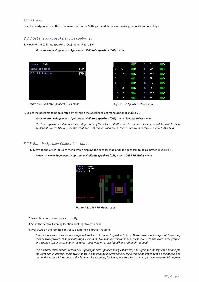
66 | P a g e
8.2.1.3 Phones
Select a headphone from the list of names set in the Settings: Headphones menu using the ADJ+ and ADJ- keys.
8.2.2 Set the loudspeakers to be calibrated
1. Move to the Calibrate speakers (CAL) menu (Figure 8-6).
Move to: Home Page menu: Apps menu: Calibrate speakers (CAL) menu:
2. Select the speakers to be calibrated by entering the Speaker select menu option (Figure 8-7).
Move to: Home Page menu: Apps menu: Calibrate speakers (CAL) menu: Speaker select menu
The listed speakers will match the configuration of the selected PRIR Sound Room and all speakers will be switched ON by default. Switch OFF any speaker that does not require calibration, then return to the previous menu (BACK key).
8.2.3 Run the Speaker Calibration routine
1. Move to the CAL PRIR Gains menu which displays the speaker map of all the speakers to be calibrated (Figure 8-8).
Move to: Home Page menu: Apps menu: Calibrate speakers (CAL) menu: CAL PRIR Gains menu
2. Insert binaural microphones correctly.
3. Sit in the central listening location, looking straight ahead.
4. Press CAL on the remote control to begin the calibration routine.
One or more short sine wave sweeps will be heard from each speaker in turn. These sweeps are output at increasing volumes to try to record sufficiently high levels in the two binaural microphones - these levels are displayed in the graphic and change colour according to the level – yellow (low), green (good) and red (high - clipped). The binaural microphones record two signals for each speaker being calibrated, one signal for the left ear and one for the right ear. In general, these two signals will be at quite different levels, the levels being dependent on the position of the loudspeaker with respect to the listener. For example, for loudspeakers which are at approximately +/- 90 degrees
Figure 8-7: Speaker select menu Figure 8-6: Calibrate speakers (CAL) menu
Figure 8-8: CAL PRIR Gains menu

67 | P a g e
to the listener, i.e. left and right surround, the microphone in the ear facing the loudspeaker will record a higher signal than the microphone in the ear facing away from the loudspeaker (Figure 8-9). The calibration routine tries to ensure that at least one of the microphones signals is recording a good (green) level by changing the level of gain for each loudspeaker being calibrated. A sticky clip indicator will show if the calibration level has clipped during the calibration. This can be cancelled using the CANCEL key on the remote. Note: The calibration sweep for the SW (subwoofer) speakers is done at the end of the routine, after all the full bandwidth speakers have been calibrated. Therefore, the user should wait until the routine has completely finished before moving BACK to the Apps menu.
5. When the calibration routine is finished press BACK to save the gain levels for each loudspeaker.
NOTE 1. If the calibration clips or the microphone levels are persistently too high, try one or both of the following options:
• Reduce the global external gain of the loudspeaker amplifiers (using an external volume control).
and/or
• Reduce the Mic gain (Home Page menu: Settings menu: System menu: Measurement settings menu: SVS Mic gain)
then run the calibration routine again.
NOTE 2. If the microphone levels are persistently too low, try one or more of the following options:
• Increase the Mic gain (Home Page menu: Settings menu: System menu: Measurement settings menu: SVS Mic gain)
and/or
• Increase the maximum sweep level (Home Page menu: Settings menu: System menu: Measurement settings menu: Max sweep Vol:)
and/or
• Increase the global external gain of the loudspeaker amplifiers (using an external volume control)
then run the calibration routine again.
If the binaural mic levels are sufficiently good (normally one green channel for each calibrated loudspeaker) then the speaker calibration for the PRIR measurement is complete. Use the back key to save the calibration settings and return to the Apps menu.
Configure and run the PRIR Measurement routine
Move to: Home Page menu: Apps menu: PRIR measurement (SPK) menu: (Figure 8-10)
Figure 8-9 Calibration routine showing the calibration levels for the right wide speaker. Note that the recorded right ear binaural signal is greater than the left ear signal.
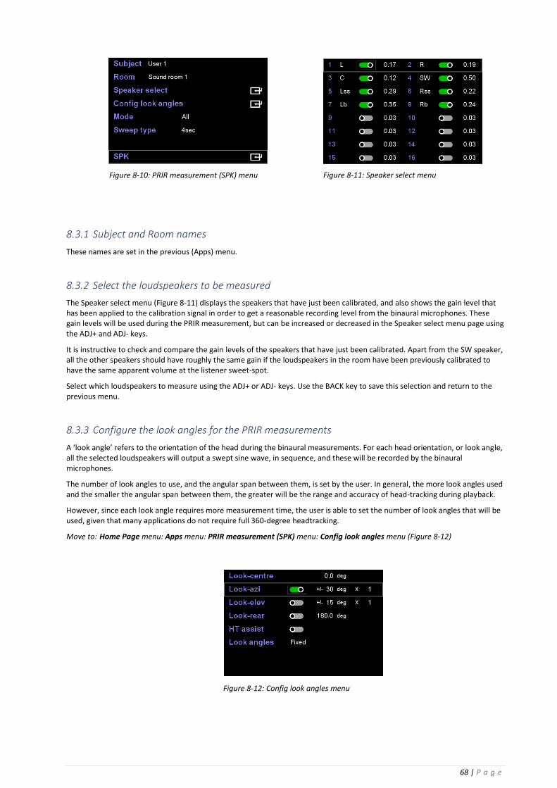
68 | P a g e
8.3.1 Subject and Room names
These names are set in the previous (Apps) menu.
8.3.2 Select the loudspeakers to be measured
The Speaker select menu (Figure 8-11) displays the speakers that have just been calibrated, and also shows the gain level that has been applied to the calibration signal in order to get a reasonable recording level from the binaural microphones. These gain levels will be used during the PRIR measurement, but can be increased or decreased in the Speaker select menu page using the ADJ+ and ADJ- keys.
It is instructive to check and compare the gain levels of the speakers that have just been calibrated. Apart from the SW speaker, all the other speakers should have roughly the same gain if the loudspeakers in the room have been previously calibrated to have the same apparent volume at the listener sweet-spot.
Select which loudspeakers to measure using the ADJ+ or ADJ- keys. Use the BACK key to save this selection and return to the previous menu.
8.3.3 Configure the look angles for the PRIR measurements
A ‘look angle’ refers to the orientation of the head during the binaural measurements. For each head orientation, or look angle, all the selected loudspeakers will output a swept sine wave, in sequence, and these will be recorded by the binaural microphones.
The number of look angles to use, and the angular span between them, is set by the user. In general, the more look angles used and the smaller the angular span between them, the greater will be the range and accuracy of head-tracking during playback.
However, since each look angle requires more measurement time, the user is able to set the number of look angles that will be used, given that many applications do not require full 360-degree headtracking.
Move to: Home Page menu: Apps menu: PRIR measurement (SPK) menu: Config look angles menu (Figure 8-12)
Figure 8-11: Speaker select menu Figure 8-10: PRIR measurement (SPK) menu
Figure 8-12: Config look angles menu

69 | P a g e
8.3.3.1 Look-azi
Look-azi is the azimuth, or rotational, angle of the head. Zero degrees is considered to be looking dead-centre. If Look-azi is enabled, the angular span of the look-angle and the number of look-angles must be set. The angular span can be set from 10 degrees to 60 degrees, and the number of look-angles can be set from 0 to 11. Some examples of these settings are:
⚫ If Look-azi is switched OFF, then only look-centre is used for the PRIR measurement (0.0 deg). In this mode no interpolation is possible between different head orientations, and therefore head-tracking during playback is not feasible.
⚫ If look-azi is switched ON and the angular span is set to +/- 30 degrees and one look angle is selected for the PRIR measurement, then headtracking is possible for head movements of +/- 30 deg during playback.
⚫ If look-azi is switched ON, the angular span is set to +/- 30 degrees, five look angles are selected for the PRIR measurement, and look-rear is switched ON, then head-tracking is possible for head movements of 360 degrees during playback.
The maximum number of look angles that can be set is 11, at an angular span of +/-15 deg. The factory default PRIR files have this configuration.
8.3.3.2 Look-elev
Look-elev is the elevation, or tilt, angle of the head.
NOTE: Elevation angles are not currently used.
8.3.3.3 Look-rear
Look-rear enables a measurement for a look-angle of 180 degrees. It complements the Look-centre look-angle of 0 degrees, and allows for 360-degree headtracking. In general, it should only be enabled if 360-degree headtracking is required and a large number of look-angles has been selected (eg 3 angles @ +/- 45 degrees or 5 angles @ +/- 30 degrees etc)
8.3.3.4 HT assist and Look angles
HT assist uses the A16 head-tracker mounted on a head-band (Figure 8-13) to determine the actual value of the Look-angle during the PRIR measurement.
⚫ If HT assist is OFF then the look angles are set to the values indicated by Look-azi (irrespective of the actual head orientation of the user).
⚫ If HT assist is ON and Look angles is set to Free, then the head-tracker, mounted on a headband on the user’s head, is used to measure the look angles during the PRIR measurement. This will normally be more accurate than not using a head-tracker. The angles are measured just before the sweeps begin for a new head orientation.
⚫ If HT assist is ON and Look angles is set to Fixed then, during the PRIR measurement procedure, the head-tracker (mounted on the user’s head) is used to guide the user to orientate their head to the fixed angles indicated in the Look-azi settings. The guiding is achieved by emitting ‘guide’ tones from the target loudspeaker that change in frequency and intensity according to the separation of the head tracker angle from the target angle. When the target angle is reached and steady the guide tones turn off and the sine wave sweeps begin for the PRIR measurement for that head orientation. This guide method also requires that the measured elevation angle be 0 deg – i.e. that the user’s head is level – before releasing the sine wave sweeps. This guiding procedure is repeated for each head orientation indicated by the Look-azi settings.
The BACK key saves the configuration for the look angles and returns to the previous menu.
Figure 8-13: Head-band for HT assist mode

70 | P a g e
8.3.4 Set the measurement mode
Move to: Home Page menu: Apps menu: PRIR measurement (SPK) menu (Figure 8-10)
8.3.4.1 All mode
In ALL mode the A16 is connected directly to the loudspeakers during the PRIR measurement, the sine sweeps are generated internally by the A16 and output to each loudspeaker in turn, and the binaural microphones are recorded directly by the A16.
8.3.4.2 Async Mode
In Async mode the A16 is not connected to the loudspeakers during the PRIR measurement, and the sine sweeps are generated externally from the A16, either from a DVD, Blu-ray or other media player, an audio work station, or some other source. The binaural microphones are still connected to the A16.
The external sine sweep signals used during an ASYNC measurement include an audible preamble that automatically configures the A16 with information relating to:
⚫ The type of audio test being run.
⚫ The number and value of the azimuth look angles.
⚫ The number and value of the elevation look angles.
⚫ The length and type of sine sweeps.
⚫ The number and ID of each speaker being measured.
⚫ The arrangement of the speakers in the room.
When set in ASYNC mode the A16 essentially waits until the preamble has been detected and decoded (through the binaural microphones in the user’s ears), configures itself according to the data in the preamble, and then records the external sine wave sweeps as they are emitted from each loudspeaker in turn. The user follows the audible head-orientation instructions which are part of the external sound files. The end of the measurement is determined by the external file, and the A16 then generates the PRIR as normal.
Due to the large number of permutations possible only some of the more common formats have been generated, and these are available in PCM and Dolby Atmos formats from the Realiser Exchange website, and other formats can be generated and downloaded through this site.
NOTE: In Async mode:
1. If HT assist is set OFF, the Look-azi span angle must be set – the span angle information is not part of the preamble.
2. If HT assist is ON then Look angles must be set to Free. In this mode the angle from the head-tracker will be recorded just before each set of sine sweeps
3. All other configuration data is provided in the preamble
NOTE: Full details for measuring PRIRs using the Async mode are provided in Appendix F.
8.3.5 Set the sweep type
Move to: Home Page menu: Apps menu: PRIR measurement (SPK) menu (Figure 8-10)
The sine sweep can be set to a length of 4 or 12 seconds, with or without an overlap. The overlap option decreases the measurement time significantly. The 12s overlapped sweep is recommended.
8.3.6 Load and run the PRIR measurement routine
Move to: Home Page menu: Apps menu: PRIR measurement (SPK) menu: SPK menu
Entering the SPK menu displays the PRIR measurement speaker map (Figure 8-14).

71 | P a g e
During the measurement procedure the Look [0.0 0.0] angles will change to indicate the current look angle (or head orientation) the subject should adopt. An example of the sequence of audible test signals is given in Figure 8-15.
NOTE: Ensure that the binaural microphones are correctly inserted in each ear canal (left mic in the left ear) and that the subject is in the sweet spot of the room facing towards the centre speaker.
To begin the PRIR measurement procedure press the SPK key on the remote control and wait for the verbal instructions as outlined in Figure 9-14. During the measurement the screen will display the speakers that are being measured, and the signal levels being recorded by the microphones.
When the procedure ends each measured speaker will have a white border (Figure 8-17).
1. A ‘Look Centre’ verbal instruction to the user to orientate their head to zero degrees.
2. A two second delay to allow the user to orientate their head.
3. Sine sweeps will begin emitting from the first speaker and continue to the last speaker.
4. A ‘Look Left’ verbal instruction to move head orientation to -30 degrees.
5. A two second delay.
6. Sine sweeps will again begin emitting from the first speaker and continue to the last speaker.
7. A ‘Look Right’ verbal instruction to move head orientation to +30 degrees.
8. A two second delay.
9. Sine sweeps will again begin emitting from the first speaker and continue to the last speaker.
Instructions 4 to 9 will be repeated for each selected look angle.
Instructions 4 to 6 will be repeated if Look-rear has been enabled.
10. End of measurement.
Figure 8-14: SPK menu showing the speaker map of the PRIR to be measured
Figure 8-16: PRIR measurement in progress using 12s overlapped sine sweeps.
Figure 8-15: Audible instructions during a PRIR measurement

72 | P a g e
8.3.7 Saving the PRIR measurement
To save the PRIR measurement press the ENTER key
The current PRIR measurement is always saved to the first slot of the PRIR recycle buffer, and other older measurements in the recycle buffer are shuffled up one slot - the measurement stored in slot 16 is overwritten and lost. Therefore, PRIR measurements in the recycle buffer should be moved to the permanent internal storage or to an external SD card.
A progress bar is displayed while the measured PRIR file is being saved.
To exit from the PRIR measurement procedure press the BACK key.
Figure 8-17: End of the PRIR measurement showing a white border around each measured speaker.

73 | P a g e
9 Measuring personalised headphone EQ filters Headphone EQ filters are used to try to flatten the frequency response of headphones when placed over a listener’s ears. Because individual’s have different ear shapes and ear canals they need individualised headphone EQ filters. Up to four different EQ filters can be created within a single HPEQ file, and any one of these four filters can be selected within a preset configuration.
9.1.1 AutoEQ filter measurement using binaural microphones
For normal headphones the standard procedure is to measure EQ automatically, using binaural microphones inserted in the listener’s ears. It is advantageous if this is done immediately after the PRIR measurement, since the microphones would generally be in the same location in the ear canal. This procedure creates two filters; an autoEQ filter from the measured data, and a flatEQ filter which is generated as flat.
9.1.2 FlatEQ filter generation for IEM-type headphones
For in-ear type headphones (IEM-type), where it is not feasible to use binaural microphones to measure the EQ automatically, there is an option to generate an HPEQ file containing a flat EQ filter (flatEQ). This procedure also creates an autoEQ filter and a flatEQ filter, but both filters are generated as flat.
In either case, once the HPEQ file has been generated, and the HPEQ file has been saved, the autoEQ or flatEQ filters may be selected for use within a preset.
9.1.3 Manual EQ modification of either the autoEQ or flatEQ filters
However, it is also possible to manually create two new filters, based on the autoEQ or flatEQ filters, using two different routines. The manual EQ stage can modify the filter created automatically (autoEQ) which, due to the position of the binaural measurement microphones, is not able to take account of any ear canal resonances. The manual EQ stage can also modify the flatEQ filter for IEM-type headphones.
9.1.3.1 Manual EQ using equal loudness pink noise – suitable for all headphones including IEM-type headphones
In the first manual routine, manLOUD, the loudness of a sub-band noise signal is adjusted so as to try to equalise the loudness between each band and thereby remove any peaks or notches. This routine does not require that the headphones are removed from the head whilst making a comparison, and is therefore suitable for use with all types of headphones, including IEMs. Optionally a PRIR may be selected for the manLOUD method, in which case the HRTF part of the impulse response of the selected virtual speaker(s) are convolved with the filtered sub-band signals in order to externalise the signal somewhat. If the PRIR is not selected the filtered sub-band signals are heard without any virtualisation – in the centre of the head.
9.1.3.2 Manual EQ using an external reference loudspeaker – suitable for normal headphones
In the second manual routine, manSPKR, the loudness of sub-band noise signals heard through a virtual loudspeaker are compared to a real loudspeaker, and the virtual sub-band levels are adjusted to match those of the real loudspeaker reference. Since this technique requires that the headphones are removed from the head during each sub-band comparison between the virtual and real loudspeakers, it is not suited to IEM-type headphones. For normal headphones the head-tracker facilitates the A/B switching between the real and virtual speakers. In the manSPKR method a PRIR must be selected, and the entire impulse response of the selected virtual speakers are convolved with the filtered sub-band signals.
NOTE: In the manual routines the base filter can be either the autoEQ or flatEQ filter, and new filters are created, either manLOUD or manSPKR. Once the manual EQ routines are completed the generated filters are added to the HPEQ file, and may be selected as the HPEQ within a preset, thus facilitating the creation of filters for both headphones and IEMs.
Configure the A16 for an automatic HPEQ measurement of normal headphones.
9.2.1 Connect the binaural microphones to the A16
Insert the binaural microphones into the subject’s ear canals – ensuring that the microphones in the left and right ears are connected to the L(eft) and R(ight) microphone inputs of the A16.
9.2.2 Set the headphone A output gain
Set the headphone gain of User A appropriately for the headphones to be measured (set to LOW if unsure)
9.2.3 Connect headphones to the User A HP jack
The HPEQ is only measured at the Headphone A output. Once connected to the A output place the headphones correctly over the ears, taking care not to disturb the binaural microphones in the ear canals.

74 | P a g e
Configure the HPEQ options
9.3.1 Set the Subject name and Headphone name
Move to: Home Page menu: Apps menu (Figure 9-1)
9.3.1.1 Select a Subject name
This name is selected from the list created in the Users Menu (Home Page menu: Settings menu: Users menu).
9.3.1.2 Select the Phones name
This name is selected from the list created in the Headphones Menu (Home Page menu: Settings menu: Headphones menu).
9.3.2 Set the HPEQ measurement options
Move to: Home Page menu: Apps menu: Headphone EQ (HP) menu (Figure 9-1: Apps menu)
9.3.2.1 Subject, Phones
These names are descriptive and become part of the HPEQ file name. They are set in the previous menu.
9.3.2.2 Man EQ Start, Curve, Man EQ HPEQ, Man EQ PRIR, Man EQ spkr
These options are not relevant and are ignored for the autoEQ measurement procedure.
9.3.2.3 HP (run)
Set to Measure EQ response (autoEQ) and press the ENTER command. This loads and runs the autoEQ measurement routine displayed in Figure 9-3.
NOTE: Ensure that the binaural microphones are inserted in the correct ears, and that the left headphone cup is on the left ear.
NOTE: Press the HP key to begin the automatic headphone EQ procedure.
Figure 9-1: Apps menu
Figure 9-2: Headphone EQ (HP) menu

75 | P a g e
An initial calibration routine will send short sine sweeps, at increasing volumes, from the left and right drivers of the headphones in order to find an adequate microphone level.
Immediately following the calibration, the measurement routine begins, and a long sine sweep is output first from the left headphone driver (Figure 9-4) and then from the right headphone driver (Figure 9-5).
The graphic icon shows the level of the sine sweep output from the headphone (outer meters) and the recorded level in the microphones (inner meters).
During the calibration and measurement routines observe the recorded levels of the microphones.
If the microphone level is too low (peaking at yellow):
1. Change the GAIN switch of the HP output of User A to a higher setting.
and/or
2. Increase the binaural microphone gain
(Home Page menu: Settings menu: System Menu: Measurement settings menu: SVS mic gain)
If the microphone level is too high (peaking at red):
1. Change the GAIN switch of the HP output of User A to a lower setting.
and/or
2 Decrease the binaural microphone gain
(Home Page menu: Settings menu: System Menu: Measurement settings menu: SVS mic gain)
Figure 9-5: Automatic headphone EQ measurement showing the headphone signal and the recorded level in the right binaural microphone.
Figure 9-4: Automatic headphone EQ measurement showing the headphone signal and the recorded level in the left binaural microphone.
Figure 9-3 Automatic EQ measurement (autoEQ).
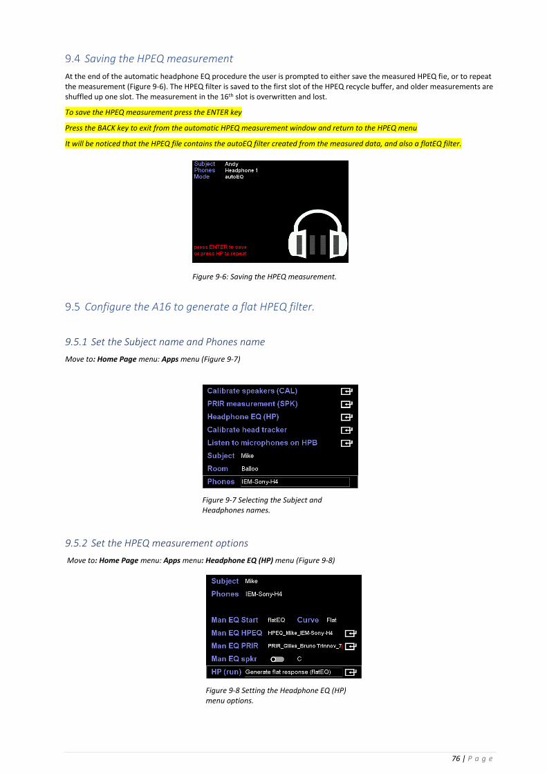
76 | P a g e
Saving the HPEQ measurement
At the end of the automatic headphone EQ procedure the user is prompted to either save the measured HPEQ fie, or to repeat the measurement (Figure 9-6). The HPEQ filter is saved to the first slot of the HPEQ recycle buffer, and older measurements are shuffled up one slot. The measurement in the 16th slot is overwritten and lost.
To save the HPEQ measurement press the ENTER key
Press the BACK key to exit from the automatic HPEQ measurement window and return to the HPEQ menu
It will be noticed that the HPEQ file contains the autoEQ filter created from the measured data, and also a flatEQ filter.
Configure the A16 to generate a flat HPEQ filter.
9.5.1 Set the Subject name and Phones name
Move to: Home Page menu: Apps menu (Figure 9-7)
9.5.2 Set the HPEQ measurement options
Move to: Home Page menu: Apps menu: Headphone EQ (HP) menu (Figure 9-8)
Figure 9-6: Saving the HPEQ measurement.
Figure 9-7 Selecting the Subject and Headphones names.
Figure 9-8 Setting the Headphone EQ (HP) menu options.

77 | P a g e
9.5.2.1 Subject, Phones
These names are set in the previous menu.
9.5.2.2 Man EQ Start, Curve, Man EQ HPEQ, Man EQ PRIR and Man EQ Spkr
These options are not relevant and are ignored for the flatEQ measurement procedure.
9.5.2.3 HP (run)
Set to Generate flat response (flatEQ) and press the ENTER command to generate the filter and HPEQ file. No actual measurement is necessary.
NOTE: It will be noticed that the HPEQ file created using the Generate flat response (flatEQ) option includes an autoEQ filter and a flatEQ filter. Both of these filters are flat.
Manual HPEQ adjustment using an external loudspeaker as reference.
9.6.1 Set the HPEQ measurement options
Move to: Home Page menu: Apps menu: Headphone EQ (HP) menu (Figure 9-9)
9.6.1.1 Subject, Phones
These names are set in the previous menu but are not relevant for the manual EQ stage.
9.6.1.2 Man EQ Start
Selects the base filter to be adjusted. The options are autoEQ or flatEQ.
9.6.1.3 Curve
The frequency response curve of the band-limited pink noise excitation signal. The options are flat, equal-loudness-80 or equal-loudness-20.
9.6.1.4 Man EQ HPEQ
Selects the HPEQ file that contains the filter to be manually adjusted. The ENTER command moves to the HPEQ file select menus allowing the desired HPEQ file to be selected. Note that the Man EQ Start option selects the actual filter from within this HPEQ file – select either the autoEQ or flatEQ filter.
9.6.1.5 Man EQ PRIR
Selects the PRIR file from which the virtual speaker(s) are selected that will be used to compare to the real external speaker(s). The ENTER command moves to the PRIR file select menus allowing the desired PRIR to be selected. Normally this PRIR will have been measured using the same external reference speaker and room – in other words the comparison should be between an external speaker in a room and the measured PRIR of this speaker in the same location in the same room.
9.6.1.6 Man EQ Spkr
Selects the virtual speaker(s) that will be used during the A/B comparison with the external speaker(s). The options are centre, left + right, left + centre + right. The toggle switch option is ignored since this manual EQ mode always requires at least one virtual speaker.
Figure 9-9 Configuration of HPEQ parameters for manual adjustment of an autoEQ filter, by comparing a virtual centre speaker from a measured PRIR against a real external loudspeaker as reference. The selected sub-band pink noise signals have a flat response curve.
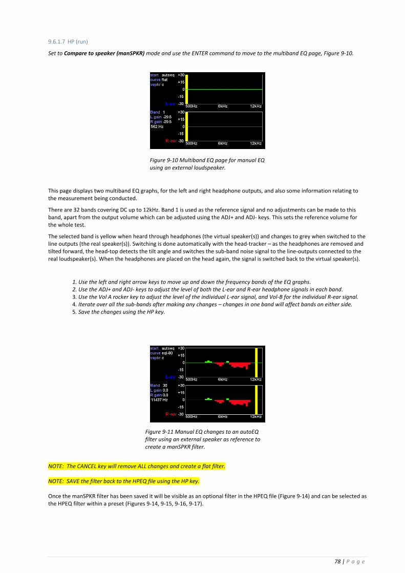
78 | P a g e
9.6.1.7 HP (run)
Set to Compare to speaker (manSPKR) mode and use the ENTER command to move to the multiband EQ page, Figure 9-10.
This page displays two multiband EQ graphs, for the left and right headphone outputs, and also some information relating to the measurement being conducted.
There are 32 bands covering DC up to 12kHz. Band 1 is used as the reference signal and no adjustments can be made to this band, apart from the output volume which can be adjusted using the ADJ+ and ADJ- keys. This sets the reference volume for the whole test.
The selected band is yellow when heard through headphones (the virtual speaker(s)) and changes to grey when switched to the line outputs (the real speaker(s)). Switching is done automatically with the head-tracker – as the headphones are removed and tilted forward, the head-top detects the tilt angle and switches the sub-band noise signal to the line-outputs connected to the real loudspeaker(s). When the headphones are placed on the head again, the signal is switched back to the virtual speaker(s).
1. Use the left and right arrow keys to move up and down the frequency bands of the EQ graphs. 2. Use the ADJ+ and ADJ- keys to adjust the level of both the L-ear and R-ear headphone signals in each band. 3. Use the Vol A rocker key to adjust the level of the individual L-ear signal, and Vol-B for the individual R-ear signal. 4. Iterate over all the sub-bands after making any changes – changes in one band will affect bands on either side. 5. Save the changes using the HP key.
NOTE: The CANCEL key will remove ALL changes and create a flat filter. NOTE: SAVE the filter back to the HPEQ file using the HP key. Once the manSPKR filter has been saved it will be visible as an optional filter in the HPEQ file (Figure 9-14) and can be selected as the HPEQ filter within a preset (Figures 9-14, 9-15, 9-16, 9-17).
Figure 9-10 Multiband EQ page for manual EQ using an external loudspeaker.
Figure 9-11 Manual EQ changes to an autoEQ filter using an external speaker as reference to create a manSPKR filter.

79 | P a g e
Manual HPEQ adjustment using an equal loudness curve.
9.7.1 Set the HPEQ measurement options
Move to: Home Page menu: Apps menu: Headphone EQ (HP) menu (Figure 9-12)
9.7.1.1 Subject, Phones
These names are set in the previous menu but are not relevant to the manual EQ stage.
9.7.1.2 Man EQ Start
Selects the base filter within the HPEQ file to be adjusted. The options are autoEQ or flatEQ.
9.7.1.3 Curve
Selects the frequency response curve for the sub-band noise excitation signals. The options are flat, equal-loudness-20, equal-loudness-80.
9.7.1.4 Man EQ HPEQ
Selects the HPEQ file that contains the filter to be manually adjusted. The ENTER command moves to the HPEQ file select menus, allowing the desired HPEQ file to be selected. Note that the Man EQ Start option selects the actual filter from within
this HPEQ file – either the autoEQ or flatEQ filter.
9.7.1.5 Man EQ PRIR
Optionally selects the PRIR file from which the virtual speaker(s) are selected. The HRTF of the impulse responses of the virtual speakers are convolved with the filtered sub-band noise signals to externalise the headphone signal. The ENTER command moves to the PRIR file select menus, allowing the desired PRIR to be selected.
9.7.1.6 Man EQ Spkr
When toggled ON this enables the selection of a PRIR file and selects the named virtual speakers. The virtual speaker options are centre, left + right, left + centre + right. Only the HRTF part of the virtual speaker impulse responses is convolved. This gives some spatiality to the signal but removes any room response.
If toggled OFF the sub-band noise signal is played directly to the left and right headphone outputs, and the PRIR file and virtual speaker(s) selection are both ignored.
9.7.1.7 HP (run)
Set to Adjust equal loudness (manLOUD) and use the ENTER command to move to the multiband EQ stage (Figure 9-13).
This page displays the same two-channel multiband EQ graph, for the left and right headphone outputs, and also some information relating to the measurement being conducted.
The selected band is yellow but there is no external speaker and therefore no switching of the signal is necessary.
1. Use the left and right arrow keys to move up and down the frequency bands of the EQ graphs. 2. Use the ADJ+ and ADJ- keys to adjust the level of both the L-ear and R-ear headphone signals in each band. 3. Use the Vol A rocker key to adjust the level of the individual L-ear signal, and Vol-B for the R-ear signal.
4. Iterate over all the sub-bands after making any changes – changes in one band will affect bands on either side.
5. Save the changes using the HP key.
Figure 9-12 Configuration of the HPEQ menu options for manual EQ using the equal loudness technique. The flatEQ filter of the selected HPEQ file will be adjusted using an eqal-loudness-80 curve for the sub-band noise signals, and the headphone signals will NOT be virtualised with a PRIR.

80 | P a g e
NOTE: The objective is to remove any peaks or troughs between the sub-bands, using Band 1 as the reference level. NOTE: The CANCEL key will remove ALL changes and create a flat filter. NOTE: SAVE the filter back to the HPEQ file using the HP key. Once the manLOUD filter has been saved it will be visible as an optional filter in the HPEQ file (Figure 9-14) and can be selected as the HPEQ filter within a preset (Figures 9-14, 9-15, 9-16 and 9-17).
Figure 9-13 Manual EQ changes to a flatEQ filter, using equal loudness sub-band noise signals.
Figure 9-15 File information showing the contents of an HPEQ file in the recycle buffer. Three filters are available – autoEQ, manLOUD and manSPKR.
Figure 9-14 Selecting an HPEQ file to configure Preset 2.
Figure 9-17 Selecting the manLOUD filter of the selected HPEQ file for Preset 2.
Figure 9-16 Confirmation of the selected HPEQ filter from the Speaker Map display informational page of the active preset.

81 | P a g e
10 Configuring a Listening Room from one or more PRIRs Listening rooms are configured to reflect the varying loudspeaker setups of different audio decoding formats, such as Dolby Atmos and DTS:X, and other formats. The individual loudspeakers that make up these formats are matched to personalised room impulse response (PRIR) data that contain virtualised versions of the same loudspeakers. A completely virtualised listening room of any format is thereby created suitable for headphone rendering. Listening rooms also contain parameters relating to bass management, reverberation control, stereo mix-down control, and for generating tactile output signals suitable for driving bass-shakers.
Select the room type: Atmos, DTS:X or PCM
Move to: Home Page menu: Listening Rooms menu (Figure 10-1)
The Listening Rooms are listed under three headings corresponding to Dolby Atmos, DTS:X, and PCM, allowing for differences in virtual speaker positions and speaker naming conventions depending on the different formats (Tables 1, 2 and 3 in Appendix A). This list will be increased as new formats emerge and become popular.
Up to 32 different Atmos rooms, 32 DTS:X rooms and 32 PCM rooms can be configured and saved.
Select the room type and use the ENTER key command to move to the selected room configuration menu (Figure 10-4).
Configure the selected listening room
10.2.1 Select a room number
Up to 32 different Atmos, DTS:X or PCM rooms can be configured and stored, prior to loading into a preset. Rooms 1 to 4 of all three room-types are used for factory default settings, and therefore it is recommended that these rooms are not changed, and that rooms from 5 to 32 only are customised.
10.2.2 Unlock a room to change its configuration
If a room is locked (red key) the configuration parameters can be viewed but cannot be changed (Figure 10-4). Unlock a room using the ADJ+ or ADJ- keys in order to edit the parameters (Figure 10-3).
Figure 10-2: Accessing the Listening Rooms menu from the Home Page menu
Figure 10-3: An unlocked Atmos listening room configuration.
Figure 10-4: A locked Atmos listening room configuration.
Figure 10-1: Listening Rooms menu

82 | P a g e
10.2.3 Set the Listening Mode
Use the ADJ+ and ADJ- keys to adjust the listening mode to the preferred format. Dolby Atmos formats have an additional option for Dolby Enabled speakers which should be set correctly for AV listening if used.
The listening mode defines the number and arrangement of speakers for a particular listening room configuration. There are over 50 pre-configured listening modes for Dolby Atmos ranging from 2.0ch to 9.1.6ch, and for each mode the audio channels from 1 to 16 are populated with reference speaker names (Ref) that match the selected listening mode. For DTS:X listening rooms there are also over 50 pre-configured listening modes ranging from 2.0ch to 9.2.2h. In the Dolby Atmos and DTS:X listening modes the reference speaker names cannot be changed, and the channel number assigned to each speaker is also fixed – the channel numbers correspond to the 16-channel phono outputs on the rear panel of the A16. Figure 10-5 shows the reference speaker names for DTS:X in listening mode 2.0ch as L(eft) and R(ight) for channels 1 and 2. Figure 10-6, Figure 10-7 and Figure 10-8 show the reference speaker names for Dolby Atmos listening mode 9.1.6ch. For PCM listening rooms, the user can edit the reference speaker names in the pre-configured listening modes, and can also create custom layouts.
NOTE: Tables 1, 2 and 3 in Appendix A: Listening Rooms Loudspeaker Configurations list all the configurations and speaker labels available for Dolby Atmos, DTS:X and PCM listening rooms.
Figure 10-6: Reference loudspeaker names for Dolby Atmos 9.1.6ch (menu page 1)
Figure 10-8: Reference loudspeaker names for Dolby Atmos 9.1.6ch (menu page 2)
Figure 10-7: Reference loudspeaker names for Dolby Atmos 9.1.6ch (menu page 3)
Figure 10-5 DTS:X listening mode 2.0ch

83 | P a g e
Select virtual speakers for a Listening Mode from a PRIR file
Virtual speakers are the key component of SVS headphone rendering, and essentially recreate over headphones the experience of listening to reference loudspeakers.
To select virtual speakers for a particular listening mode, move the selection box to any reference speaker (Figure 10-10) and press the ENTER command key. This brings up the PRIR source selection menu (Figure 10-9).
PRIRs can be selected from permanent storage, the recycle buffer or from the factory PRIR files (Figure 10-11).
Any of the PRIR files in each source location can be chosen using the numerical selector at the top of the page. Information that
describes each PRIR is also shown in order to identify and select a particular file. For example, the Location option will show an
image of the room (if an image has been attached to the file).
1. Select the source of the PRIR file using the ENTER command key and move to the PRIR select menu (Figure 10-11). 2. Choose one PRIR file from the source location with the ADJ+ and ADJ- keys, using the information displayed. 3. Finally, select either ONE matching speaker from the PRIR, or select ALL matching speakers from the PRIR.
10.3.1 Select one matching speaker
This menu option gives access to all the individual virtual speakers in the selected PRIR, allowing any single speaker to be selected. For example, Figure 10-12 shows a L(eft) virtual speaker being individually chosen. Once selected the display reverts to the Listening Room configuration menu, and now shows the virtual speaker label, the virtual room name and the azimuth and elevation angles for that chosen virtual speaker (Figure 10-13).
To select more individual virtual speakers, move the selection box to the correct channel in the Listening Room and repeat the procedure.
Virtual speakers that are already attached to channels will be over-written by any new selection.
Figure 10-10 To select virtual speakers to populate a Listening room, move the selection box to the first channel and use the ENTER command.
Figure 10-9 Selecting the PRIR file - choose the source.
Figure 10-11 Select the correct PRIR.

84 | P a g e
CAUTION: If there is a mis-match in names between the Reference and Virtual names, the A16 will not display the mis-matched speaker in the Speaker Map display if this Listening Room is used for a preset. Furthermore, the mis-matched speaker will not rendered to SVS headphones, nor will it be output to the line outputs in the AV mode.
Figure 10-14 illustrates a speaker mis-match in channel 2 of a Listening Room, where the Right Surround virtual speaker (Rs) has been selected rather than the Right speaker reference name. This mis-match means that channel 2 is ignored if this listening room is used in a preset, as illustrated in Figure 10-15.
10.3.2 Select all matching speakers
This menu option automatically selects all the virtual speakers in the PRIR that match the reference speaker names in the Listening Room, and then returns the system to the Listening Room configuration menu. Information related to the virtual speakers is also displayed.
Figures 10-17, 10-18 and 10-19 illustrate matching virtual speakers in a 7.1.4ch listening room all taken from a single PRIR measurement. For this format (Atmos 7.1.4ch) some channels are not used and therefore have neither a reference name nor a virtual speaker.
NOTE: Using the Select all matching speakers option will over-write all matching virtual speaker names - even if these names have already been selected in a listening room. However, using both selection options allows a Listening Room to be created from virtual speakers selected from multiple PRIR files.
Figure 10-12 Selecting an individual l(eft) speaker from a PRIR file.
Figure 10-13 The selected L(eft) virtual speaker, from the PRIR, is inserted into the Listening Room, at the location of the selection box.
Figure 10-14 Mis-matched speaker names in a Listening room - the virtual speaker from the PRIR (Rs) does not match the reference speaker name of the Listening Room (R).
Figure 10-15 Mis-matched speakers in the Listening Room (Figure 10-14 ) are not displayed in the Speaker Map of the preset, and are not rendered to headphones. Only the matching L(eft) speaker will be heard.

85 | P a g e
If any reference speakers cannot be matched the virtual speaker names will be displayed as blank entries (Figure 10-20). These unmatched speakers will NOT be displayed in the preset Speaker Map and will NOT be rendered to the SVS headphone output (Figure 10-21), and will NOT be sent to the AV line outputs for listening through loudspeakers.
10.3.3 Normalise speaker volumes
When enabled, this option equalises the loudness of all the virtual speakers in a configured listening room. This may be desirable if the listening room is constructed from virtual speakers from different PRIRs, since the PRIRs may have been measured in different rooms with differing reverberation characteristics. In this routine only the direct HRTF portion of the virtual speakers are used to calculate the normalisation factor for each speaker.
When disabled this option retains any naturally occurring inter-speaker level differences between the virtual speakers in a listening room.
Figure 10-19 All matched speakers in a 7.1.4ch listening room (page 1).
Figure 10-18 All matched speakers in a 7.1.4ch listening room (page 2).
Figure 10-17 All matched speakers in a 7.1.4ch listening room (page 3).
Figure 10-20 Unmatched Left Top Mid and Right Top Mid reference speakers. The PRIR selected did not contain virtual speakers with these names.
Figure 10-21 The unmatched speakers, Ltm and Rtm, are not displayed in the Speaker Map for the preset. The Left Wide and RIght Wide speakers are also missing in this listening room.
Figure 10-16 Speaker map information for the currently running preset. Some channels are not used.

86 | P a g e
Set Bass Management / Tactile outputs / Stereo mixdown outputs
Move to: Home Page menu: Listening Rooms menu: Atmos or DTS:X or PCM rooms menu: Manage Bass/Reverb/Tactile menu
This menu sets listening room parameters related to bass management, reverberation control, the generation of tactile outputs for an external ‘butt-kicker’ device, and the generation of a non-virtualised stereo headphone mix from a selection of the audio input channels.
NOTE: Some of the bass management controls are designed for both SVS headphone listening and AV loudspeaker listening modes - these are labelled hp/av. Other controls are for SVS headphone only – these are labelled hp.
NOTE: Please refer to Appendix J: Bass Management, which illustrates the signal paths for the bass managed signals and their controls.
NOTE: There are different bass management options for Dolby Atmos / DTS:X listening rooms and PCM listening rooms. These differences are reflected in the differing menu options for these rooms.
10.4.1 Dolby Atmos and DTS:X listening rooms
For Dolby Atmos or DTS:X listening rooms there are two different stages of bass management. The first stage (labelled hp/av) is controlled by setting each loudspeaker size and the corner frequency of the global low-pass filter for all the speakers. The bass-managed signals can be output to real (AV loudspeaker mode) or virtual loudspeakers (SVS headphone mode). This bass management stage can also be by-passed, in which case only the LFE signal is sent to the sub-woofer speaker, real or virtual.
For SVS headphone rendering there are two alternative bass management modes (labelled hp) that can be engaged – one mode uses a virtual sub-woofer loudspeaker, whilst the second mode, Direct Bass, by-passes the virtual sub-woofer. The Direct Bass mode was developed to circumvent some of the problems associated with measuring and acquiring good virtual sub-woofer speakers, and relies on the observation that low-frequency acoustic signals have little or no perceived directionality. In Direct Bass mode the virtual sub-woofer speaker in the listening room is by-passed, and the bass-managed sub-woofer signal is instead fed directly into the left and right headphone outputs.
There are therefore four bass management options for Dolby Atmos and DTS:X listening rooms.
1. hp/av bass management ON and hp Direct Bass ON. (Figure 20.1, Appendix J: Bass Management) 2. hp/av bass management ON and hp Direct Bass OFF. (Figure 20.3, Appendix J: Bass Management) 3. hp/av bass management OFF and hp Direct Bass ON. (Figure 20.2, Appendix J: Bass Management) 4. hp/av bass management OFF and hp Direct Bass OFF. (Figure 20.4, Appendix J: Bass Management)
10.4.2 PCM listening rooms
For AV loudspeaker listening using a PCM listening room there is no hp/av bass management stage, since the expectation is that bass management of the line output audio signals will occur after the A16.
For SVS headphone rendering using a PCM listening room there are three options. Bass management can be enabled or disabled and, if enabled, the bass-managed low-frequency signal can be rendered through a virtual sub-woofer speaker or sent directly to the headphone outputs using the Direct Bass mode.
There are therefore three bass management options for PCM listening rooms.
1. Bass management set to Direct Bass. (Figure 20.5, Appendix J: Bass Management) 2. Bass management set to Virtual sub-woofer. (Figure 20.6, Appendix J: Bass Management) 3. Bass management set OFF. (Figure 20.7, Appendix J: Bass Management)
10.4.3 Bass Management for Dolby Atmos or DTS:X listening rooms
Please refer to Appendix J: Bass Management, diagrams 20.1, 20.2, 20.3 and 20.4. for information on the function or each of these parameters.
Figure 10-22: Manage Bass/Reverb/Tactile menu for Dolby Atmos or DTS:X listening rooms.

87 | P a g e
10.4.3.1 hp/av LFE +10db
The LFE channel of movie soundtracks is usually reduced by 10dB.Therefore the LFE channel should normally be boosted by 10dB before being sent to a real or virtualised sub-woofer speaker.
If set ON the LFE input is boosted by 10dB. If set OFF the LFE channel is not boosted.
10.4.3.2 hp/av SW volume
The gain of the bass-managed signal sent to the sub-woofer speaker can be set from -30dB to +10dB.
10.4.3.3 hp/av BM, LPF
Toggles ON or OFF the bass management (BM) control of audio signals (bitstream and PCM), and sets the corner-frequency of the low-pass filter for the bass-management routine (LPF=40Hz to 200Hz in steps of 10Hz). The ENTER command displays the Speaker Size configuration page, which is used to set the size of all the speakers in the listening room (Figure 10-23).
The sizes of each speaker, large or small, and the low-pass filter frequency, are used as parameters in the bass management routine to determine the routing of the low-frequency part of the audio signal passing through each speaker, both in the virtual SVS headphone mode and in the real AV loudspeaker mode.
There are a number of different bass-management routines which have been designed for particular modes of operations, and these are all described more fully in Appendix J: Bass Management.
10.4.4 Bass Management for PCM listening rooms
For SVS headphone rendering of PCM audio signals the Realiser A16 provides three options for Bass Management.
1. Bass management OFF. 2. Bass management using a virtual sub-woofer speaker. 3. Bass management using Direct Bass mode that by-passes the virtual sub-woofer speaker.
For AV loudspeaker listening of PCM input signals the Realiser A16 does NOT include options for bass management. It is assumed that bass management will occur after the audio signals are output from the A16.
Figure 10-23 Setting the sizes of speaker pairs as part of the bass-management configuration of a listening rooom. This room is Dolby Atmos 7.1.4ch with a small centre speaker, and small top speakers.
Figure 10-24 Manage Bass/Reverb/Tactile menu for PCM listening rooms.

88 | P a g e
10.4.4.1 hp LFE +10dB
If set ON, the LFE input signal is boosted by 10dB. On movie soundtracks the LFE is normally reduced by 10dB during production, and the signal is then boosted by 10dB in the movie theatres.
10.4.4.2 hp SW volume
Allows the gain of the sub-woofer virtual speaker to be amplified or reduced in the range +12dB to -30dB. A value of 0.0dB implies that the virtual sub-woofer volume is not altered.
10.4.4.3 hp BM
Bass Management (BM) can be set OFF or Virtual or Direct.
If set to Virtual, bass management is enabled, and a virtual sub-woofer speaker is used for the final bass-managed low-frequency signal. (Figure 20.6, Appendix J: Bass Management.)
If set to Direct, bass management is enabled, but the final bass-managed low-frequency signal is sent directly to the headphone outputs, and by-passes the virtual sub-woofer speaker of the PCM listening room. (Figure 20.5, Appendix J: Bass Management.)
If set to OFF, bass management is disabled, and the LFE input signal is sent to the virtual sub-woofer speaker of the PCM listening room. (Figure 20.7, Appendix J: Bass Management.)
10.4.4.4 Vol
If bass management is enabled, Vol controls the output level of the low-frequency summation stage of the bass management routine, and is set from +12dB to -30dB.
10.4.4.5 LPF
If bass management is enabled, LPF sets the corner frequency of the low-pass filter for the bass management routine, and is set to 60, 80 or 120Hz.
10.4.5 Limit Reverb
If set ON, this limits the reverberation time in the virtual listening room to the set value.
If set OFF the reverberation time is set to the maximum value of 0.75ms.
10.4.6 Tactile (mixdown)
If set ON, the volume of each channel of the 2-ch tactile output signal can be reduced or amplified, and the corner frequency of the 4th order, low-pass, IIR filter can be set (60/80/120Hz).
In order to specify which channels will be used to create the tactile output use the ENTER command to move to the Tactile Mixdown menu (Diagrams 10-26 and 10-25).
In the above example, the low-pass filtered components of the L, R, C and SW channels of a 9.1.6ch signal are being mixed, at varying gains, to the 2-ch tactile outputs, Lt and Rt. Some of the low-pass filtered signals are being sent to a single output channel (either Lt or Rt) and some are being sent to both channels equally (Lt+Rt). The remaining surround and height channels of the 9.1.6ch signal are not enabled and are therefore not contributing to the tactile output.
Figure 10-25: Tactile output (menu page 1)
Figure 10-26: Tactile output (menu page 2)

89 | P a g e
10.4.7 Stereo (mixdown)
If set ON, a full-band, non-virtualised, stereo headphone signal may be derived from all available input channels. The gain of this headphone signal can also be adjusted.
In order to specify which channels are used to create the full-bandwidth headphone signal use the ENTER command to move to the Stereo Mixdown menu (Figure 10-27).
In the above example (Figure 10-27) all the channels of a 7.1ch signal are being used, with varying set gains, to create the 2-ch stereo headphone signal, Lh and Rh. Some of the channels are being sent to just one channel (either Lh or Rh) and some are being sent to both channels equally (Lh+Rh).
When enabled, the non-virtualised stereo mix-down signal is routed to the headphone output using the speaker icon key
on the remote control. The virtualised SVS signal is routed to the headphone output using the headphone icon key on the remote control – allowing a direct comparison to be made quickly between the virtualised SVS and the non-virtualised stereo headphone modes.
NOTE: Because stereo mix-down is engaged using the SPEAKER ICON key on the remote control, the AV mode must be DISABLED for the active preset to engage stereo mixdown. If AV mode is enabled, the SPEAKER ICON key will route the audio signals to the multichannel line outputs.
General notes for Configuring a Listening Room
NOTE 1: To prevent unintentional changes being made to the configuration of the Listening Room, it is recommended that the room be locked before being saved.
NOTE 2: To save the Listening Room configuration use the BACK key from page 1 of the Listening Room configuration menu. A progress bar will become visible in the top right-hand corner of the menu screen. This will return the display to the Listening Rooms menu (Figure 11-2).
NOTE 3: After the Listening Room has been saved it may be selected as one of the three listening rooms for a preset.
Figure 10-27: Stereo Mixdown menu

90 | P a g e
11 Appendix A: Listening rooms loudspeaker configurations Dolby Atmos Listening Rooms loudspeaker configurations
Line Output Channel Number
# Mode 1 2 3 4 5 6 7 8 9 10 11 12 13 14 15 16
1 2.0 L R
2 2.1 L R SW
3 2.2 L R SW SW2
4 2.0.2m L R Ltm Rtm
5 2.1.2m L R SW Ltm Rtm
6 2.2.2m L R SW SW2
7 3.0 L R C
8 3.1 L R C SW
9 3.2 L R C SW SW2
10 3.0.2m L R C Ltm Rtm
11 3.1.2m L R C SW Ltm Rtm
12 3.2.2m L R C SW SW2 Ltm Rtm
13 4.0 L R Ls Rs
14 4.1 L R SW Ls Rs
15 4.2 L R SW Ls Rs SW2
16 4.0.2m L R Ls Rs Ltm Rtm
17 4.1.2m L R SW Ls Rs Ltm Rtm
18 4.2.2m L R SW Ls Rs SW2 Ltm Rtm
19 5.0 L R C Ls Rs
20 5.1 L R C SW Ls Rs
21 5.2 L R C SW Ls Rs SW2
22 5.0.2m L R C Ls Rs Ltm Rtm
23 5.1.2m L R C SW Ls Rs Ltm Rtm
24 5.2.2m L R C SW Ls Rs SW2 Ltm Rtm
25 5.0.4 L R C Ls Rs Ltf Rtf Ltr Rtr
26 5.1.4 L R C SW Ls Rs Ltf Rtf Ltr Rtr
27 5.2.4 L R C SW Ls Rs SW2 Ltf Rtf Ltr Rtr
28 5.0.6 L R C Ls Rs Ltf Rtf Ltm Rtm Ltr Rtr
29 5.1.6 L R C SW Ls Rs Ltf Rtf Ltm Rtm Ltr Rtr
30 5.2.6 L R C SW Ls Rs SW2 Ltf Rtf Ltm Rtm Ltr Rtr
31 6.0 L R Lss Rss Lb Rb
32 6.1 L R SW Lss Rss Lb Rb
33 6.2 L R SW Lss Rss Lb Rb SW2
34 6.0.2m L R Lss Rss Lb Rb Ltm Rtm
35 6.1.2m L R SW Lss Rss Lb Rb Ltm Rtm
36 6.2.2m L R SW Lss Rss Lb Rb SW2 Ltm Rtm
37 7.0 L R C Lss Rss Lb Rb
38 7.1 L R C SW Lss Rss Lb Rb
39 7.2 L R C SW Lss Rss Lb Rb SW2
40 7.0.2m L R C Lss Rss Lb Rb Ltm Rtm
41 7.1.2m L R C SW Lss Rss Lb Rb Ltm Rtm
42 7.2.4h L R C SW Lss Rss Lb Rb SW2 Ltf Rtf Ltr Rtr
43 7.2.2m L R C SW Lss Rss Lb Rb SW2 Ltm Rtm
44 7.0.4 L R C Lss Rss Lb Rb Ltf Rtf Ltr Rtr

91 | P a g e
45 7.1.4 L R C SW Lss Rss Lb Rb Ltf Rtf
46 7.2.4 L R C SW Lss Rss Lb Rb SW2 Ltf Rtf Ltr Rtr
47 7.0.6 L R C Lss Rss Lb Rb Ltf Rtf Ltm Rtm Ltr Rtr
48 7.1.6 L R C SW Lss Rss Lb Rb Ltf Rtf Ltm Rtm Ltr Rtr
49 7.2.6 L R C Lss Rss Lb Rb SW2 Ltf Rtf Ltm Rtm Ltr Rtr
50 8.0 L R Lss Rss Lb Rb Lw Rw
51 9.0.2m L R C Lss Rss Lb Rb Lw Rw Ltm Rtm
52 9.1.2m L R C SW Lss Rss Lb Rb Lw Rw Ltm Rtm
53 9.2.2m L R C SW Lss Rss Lb Rb Lw Rw Ltm Rtm SW2
54 9.0.4 L R C Lss Rss Lb Rb Lw Rw Ltf Rtf Ltr Rtr
55 9.1.4 L R C SW Lss Rss Lb Rb Lw Rw Ltf Rtf Ltr Rtr
56 9.2.4 L R C SW Lss Rss Lb Rb Lw Rw Ltf Rtf SW2 Ltr Rtr
57 9.0.6 L R C Lss Rss Lb Rb Lw Rw Ltf Rtf Ltm Rtm Ltr Rtr
58 9.1.6 L R C SW Lss Rss Lb Rb Lw Rw Ltf Rtf Ltm Rtm Ltf Rtr
Table 1 Supported loudspeaker configurations for Dolby Atmos listening rooms.

92 | P a g e
DTS:X listening rooms loudspeaker configurations
Line Output Channel Number
# Mode 1 2 3 4 5 6 7 8 9 10 11 12 13 14 15 16
1 2.0 L R
2 2.1 L R SW
3 2.2 L R SW SW2
4 3.0 L R C
5 3.1 L R C SW
6 3.2 L R C SW SW2
7 5.0 L R C Ls Rs
8 5.1 L R C SW Ls Rs
9 5.2 L R C SW SW2
10 5.0.2f L R C Ls Rs Ltf Rtf
11 5.1.2f L R C SW Ls Rs Ltf Rtf
12 5.2.2f L R C SW Ls Rs SW2 Ltf Rtf
13 5.0.2m L R C Ls Rs Ltm Rtm
14 5.1.2m L R C SW Ls Rs Ltm Rtm
15 5.2.2m L R C SW Ls Rs SW2 Ltm Rtm
16 5.0.2h L R C Ls Rs Lh Rh
17 5.1.2h L R C SW Ls Rs Lh Rh
18 5.2.2h L R C SW Ls Rs SW2 Lh Rh
19 5.0.4t L R C Ls Rs Ltf Rtf Ltr Rtr
20 5.1.4t L R C SW Ls Rs Ltf Rtf Ltr Rtr
21 5.2.4t L R C SW Ls Rs SW2 Ltf Rtf Ltr Rtr
22 5.0.4h L R C Ls Rs Lh Rh Lhs Rhs
23 5.1.4h L R C SW Ls Rs Lh Rh Lhs Rhs
24 5.2.4h L R C SW Ls Rs SW2 Lh Rh Lhs Rhs
25 7.0 L R C Lss Rss Lb Rb
26 7.1 L R C SW Lss Rss Lb Rb
27 7.2 L R C SW Lss Rss Lb Rb SW2
28 7.0.2f L R C Lss Rss Lb Rb Ltf Rtf
29 7.1.2f L R C SW Lss Rss Lb Rb Ltf Rtf
30 7.2.2f L R C SW Lss Rss Lb Rb SW2 Ltf Rtf
31 7.0.2m L R Lss Rss Lb Rb Ltm Rtm
32 7.1.2m L R SW Lss Rss Lb Rb Ltm Rtm
33 7.2.2m L R SW Lss Rss Lb Rb SW2 Ltm Rtm
34 7.0.2h L R Lss Rss Lb Rb Lh Rh
35 7.1.2h L R SW Lss Rss Lb Rb Lh Rh
36 7.1.2h L R SW Lss Rss Lb Rb SW2 Lh Rh
37 7.0.4t L R C Lss Rss Lb Rb Ltf Rtf Ltr Rtr
38 7.1.4t L R C SW Lss Rss Lb Rb Ltf Rtf Ltr Rtr
39 7.2.4t L R C SW Lss Rss Lb Rb SW2 Ltf Rtf Ltr Rtr
40 7.0.4h L R C Lss Rss Lb Rb Lh Rh Lhs Rhs
41 7.1.4h L R C SW Lss Rss Lb Rb Lh Rh Lhs Rhs
42 7.2.4h L R C SW Lss Rss Lb Rb SW2 Lh Rh Lhs Rhs
43 9.0.2f L R C Lss Rss Lb Rb Lw Rw Ltf Rtf
44 9.1.2f L R C SW Lss Rss Lb Rb Lw Rw Ltf Rtf
45 9.2.2f L R C SW Lss Rss Lb Rb Lw Rw Ltf Rtf SW2
46 9.0.2m L R C Lss Rss Lb Rb Lw Rw Ltm Rtm

93 | P a g e
47 9.1.2m L R C SW Lss Rss Lb Rb Lw Rw Ltm Rtm
48 9.2.2m L R C SW Lss Rss Lb Rb Lw Rw Ltm Rtm SW2
49 9.0.2h L R C Lss Rss Lb Rb Lw Rw Lh Rh
50 9.1.2h L R C SW Lss Rss Lb Rb Lw Rw Lh Rh
51 9.2.2h L R C SW Lss Rss Lb Rb Lw Rw Lh Rh SW2
Table 2: Supported loudspeaker configurations for DTS:X listening rooms.

94 | P a g e
PCM listening rooms loudspeaker configurations
Line Output Channel Number
# Mode 1 2 3 4 5 6 7 8 9 10 11 12 13 14 15 16
1 2.0 L R
2 2.2.2t L R SW SW2 Ltf Rtf
3 2.2.2h L R SW SW2 Lh Rh
4 3.0 L R C
5 3.2.2t L R C SW2 Ltf Rtf
6 3.2.2h L R C SW SW2 Lh Rh
7 4.0 L R Ls Rs
8 4.2.2t L R SW Ls Rs SW2 Ltf Rtf
9 4.2.2h L R SW Ls Rs SW2 Lh Rh
10 4.2.4t L R SW SW2 Ltf Rtf Ltr Rtr
11 4.2.4h L R Ls Rs SW2 Lh Rh Lhs Rhs
12 5.0 L R C Ls Rs
13 5.1 L R C SW Ls Rs
14 5.2.2t L R C SW Ls Rs SW2 Ltf Rtf
15 5.2.2h L R C SW Ls Rs SW2 Lh Rh
16 5.2.4t L R C SW Ls Rs SW2 Ltf Rtf Ltr Rtr
17 5.2.4h L R C Ls Rs SW2 Lh Rh Lhs Rhs
18 5.2.6t L R C SW Ls Rs SW2 Ltf Rtf Ltm Rtm Ltr Rtr
19 6.0 L R Lss Rss Lb Rb
20 7.0 L R C Lss Rss Lb Rb
21 7.1 L R C SW Lss Rss Lb Rb
22 7.2.2t L R C SW Lss Rss SW2 Ltf Rtf
23 7.2.2h L R C SW Lss Rss SW2 Lh Rh
24 7.2.4t L R C SW Lss Rss SW2 Ltf Rtf Ltr Rtr
25 7.2.4h L R C SW Lss Rss SW2 Lh Rh Lhs Rhs
26 7.2.6t L R C SW Lss Rss Lb Rb SW2 Ltf Rtf Ltm Rtm Ltr Rtr
27 9.0 L R C Lss Rss Lb Rb Lw Rw
28 9.2.2t L R C SW Lss Rss Lb Rb Lw Rw Ltf Rtf SW2
29 9.2.4t L R C SW Lss Rss Lb Rb Lw Rw Ltf Rtf SW2 Ltr Rtr
30 9.1.6t L R C SW Lss Rss Lb Rb Lw Rw Ltf Rtf Ltm Rtm Ltr Rtr
31 Custom#1 Any Any Any Any Any Any Any Any Any Any Any Any Any Any Any Any
32 Custom#2 Any Any Any Any Any Any Any Any Any Any Any Any Any Any Any Any
33 Custom#3 Any Any Any Any Any Any Any Any Any Any Any Any Any Any Any Any
34 Custom#4 Any Any Any Any Any Any Any Any Any Any Any Any Any Any Any Any
Table 3: PCM listening rooms loudspeaker configurations

95 | P a g e
12 Appendix B: Loudspeaker names and labels
Loudspeaker names and labels with default azimuth and elevation angles
# Label Name Azimuth Elevation Atmos DTS:X PCM PCM Custom
1 L Left -30 0 Y Y Y Y
2 R Right 30 0 Y Y Y Y
3 C Centre 0 0 Y Y Y Y
4 SW Subwoofer -44 0 Y Y Y Y
5 Ls Left surround -100 0 Y Y Y Y
6 Rs Right surround 100 0 Y Y Y Y
7 Lb Left back -120 0 Y Y Y Y
8 Rb Right back 120 0 Y Y Y Y
9 Lss Left side surround -90 0 Y Y Y Y
10 Rss Right side surround 90 0 Y Y Y Y
11 Cr Centre rear 180 0 Y
12 SW2 Subwoofer 2 44 0 Y Y Y Y
13 Lw Left wide -60 0 Y Y Y Y
14 Rw Right wide 60 0 Y Y Y Y
15 Lbs Left back surround -164 0 Y
16 Rbs Right back surround 164 0 Y
17 Lc Left centre -20 0 Y
18 Rc Right centre 20 0 Y
19 Lg Left ground -30 -20 Y
20 Rg Right ground 30 -20 Y
21 Cg Centre ground 0 -20 Y
22 Ch Centre height 0 40 Y
23 Chr Centre height rear 180 40 Y
24 T Top 0 90 Y
25 Lh Left height -30 40 Y Y Y
26 Rh Right height 30 40 Y Y Y
27 Lhs Left height side -90 40 Y Y Y
28 Rhs Right height side 90 40 Y Y Y
29 Lhr Left height rear -120 40 Y
30 Rhr Right height rear 120 40 Y
31 Ltf Left top front -44 60 Y Y Y Y
32 Rtf Right top front 44 60 Y Y Y Y
33 Ltm Left top mid -90 60 Y Y Y Y
34 Rtm Right top mid 90 60 Y Y Y Y
35 Ltr Left top rear -134 60 Y Y Y Y
36 Rtr Right top rear 134 60 Y Y Y Y
37 Lsc Left side centre -10 0 Y
38 Rsc Right side centre 10 0 Y
39 Ls1 Left surround 1 -74 0 Y
40 Rs1 Right surround 1 74 0 Y
41 Lrs1 Left rear surround 1 -110 0 Y
42 Rrs1 Right rear surround 1 110 0 Y
43 Lrs2 Left rear surround 2 -150 0 Y
44 Rrs2 Right rear surround 2 150 0 Y

96 | P a g e
45 Lhw Left height wide -60 40 Y
46 Rhw Right height wide 60 40 Y
47 Lhs1 Left height side 1 -110 40 Y
48 Rhs1 Right height side 2 -110 40 Y
49 Lbg Left back ground -120 -20 Y
50 Rbg Right back ground 120 -20 Y
Table 4: Loudspeaker names, labels and ID numbers
Notes
1. The azimuth and elevation angles are default values – the angles can be changed to match a physical loudspeaker layout during a PRIR measurement.
2. The Dolby Atmos loudspeaker labels are limited to those in Table 1.
3. The DTS:X loudspeaker labels are limited to those in Table 2.
4. The PCM loudspeaker labels are limited to those in Table 3 (modes 1 to 30).
5. The PCM Custom modes can use all the loudspeaker labels (Table 3 (modes 31 to 34)).

97 | P a g e
Graphical representation of loudspeakers in the Speaker Map display of the A16
SW
4
L
1
Lc
17
Lsc
37
C
3
Rsc
38
Rc
18
R
2
SW2
12
Lw
13
Lhw
45
Lh
25
Ch
22
Rh
26
Rhw
46
Rw
14
Ls1
39
Ltf
31
Lg
19
Cg
21
Rg
20
Rtf
32
Rs1
40
Lss
9
Lhs
27
Ltm
33
T
24
Rtm
34
Rhs
28
Rss
10
Ls
5
Lhs1
47
Ltr
35
Rtr
36
Rhs1
48
Rs
6
Lrs1
41
Lhr
29
Lbg
49
Chr
23
Rbg
50
Rhr
30
Rrs1
42
Lb
7
Lrs2
43
Lbs
15
Cr
11
Rbs
16
Rrs2
44
Rb
8
Ear level
Height
Overhead
Ground
Subwoofers
Figure 12-1: Graphical presentation of loudspeakers and their ID numbers on the Realiser A16 Speaker Map display

98 | P a g e
Graphical representation of speaker positions: loudspeaker names and ID numbers
Figure 12-2: Graphical presentation of loudspeaker positions
Lsc - 37 C - 3
Lc - 17
Rss - 10
Lw - 13
Rrs2 - 44
Rc - 18
Rsc - 38
L - 1
Ls1 - 39
Lss - 9
Rs - 6
Cr - 11
Rb - 8
Ls - 5
Lb - 7
Lrs2 - 44
Lbs - 15 Rbs - 16
Lrs1 -41 Rrs1 - 42
Rs1 - 40
Rw - 14
R - 2 Ch - 22
Lh - 25 Rh - 26
Lhw - 45
Lhs - 27 Rhs - 28
Lhr - 29 Rhr - 30
Chr - 23
Rhw - 46
Lhs1 - 47 Rhs1 - 48
Ltf - 31
Ltm - 33
Ltr - 35
Rtf - 32
Ltm - 34
Ltr - 36
T - 24
Lg - 19 Rg - 20
Cg - 21
Lbg - 49 Rbg - 50
SW - 4 SW2 - 12

99 | P a g e
13 Appendix C: Calibrating the magnetic sensor in the head-top device
Home Page menu: Apps menu: Calibrate head tracker menu:
The A16 head-tracker has three motion detecting sensors, inertial, magnetic and optical. The inertial sensor operates continuously but it can be also be stabilised, in a narrow central window, by either the magnetic or optical sensors.
If the magnetic sensor is chosen for stabilisation it is recommended that the magnetic sensor be calibrated in the headphone listening location in the room, mounted correctly on the headphones, and ideally in the same ‘head-space’.
The calibration routine aims to measure the strength and direction of the magnetic field in all directions around the head-tracker, and then uses this data to determine its orientation with respect to this external field.
The magnetic sensor may need to be re-calibrated if magnetisable objects are moved within the seating location.
Calibration procedure
Step 1. Mount the head-top on the headphones and connect the head-top as normal to the HT input A on the front panel of the A16. Step 2. Move to the seating location where you expect to use your headphones. Step 3. Start the calibration routine by selecting the Calibrate magnetics option - then push the ENTER key on the remote. NOTE: The word ‘calibrating’ will become visible on the menu line and the head-top LED with turn ORANGE Step 4. Holding the headphones in your hands, and ideally in the same head-space that the headphones would occupy when being used, tumble them around in complete 360-degree rotations in all orientations for a few minutes. The tumbling action is to allow the magnetic sensor to measure the field in ALL directions – i.e. not just in the horizontal rotational directions. Step 5. Calibration is complete when the ‘calibrating’ word disappears in the display, and the LED on the head-top turns GREEN. Step 6. Ensure that Stabilisation is set to magnetics in the HT Settings menu. Home page menu: Settings menu: System menu: HT Settings menu: Stabilisation option Step 7. Finally, wearing the headphones, navigate to the Azimuth angles display of any Preset Speaker Map, look directly at the centre speaker, and push the button on top of the head-top to set zero degrees for the magnetic sensor. With stabilisation set to magnetic, pushing the button on the head-top will re-set the zero degrees point of the magnetic sensor. Within the stabilisation window the magnetic sensor will reinforce the inertial sensor.
Magnetic error
Can be set to LOW or MED.
Figure 13-1: Calibrate head tracker menu

100 | P a g e
If set to MED the calibration routine will be less accurate but will take a shorter time to complete.
If set to LOW the calibration routine will be more accurate but will take a longer time to complete.
Magnetic error type
Can be set to HARD or HARD+SOFT
If set to HARD the calibration will be less accurate but will take a shorter time to complete.
If set to HARD+SOFT the calibration will be more accurate but will take a longer time to complete.
Calibrate magnetics
Use the ENTER key to run the magnetics calibration routine as outlined above.
NOTE: If calibration appears to be taking too long to complete, use the BACK key to terminate the calibration routine. Change the magnetic error or magnetic error type to reduce the calibration time and run the calibration routine again.

101 | P a g e
14 Appendix D: Setting up the head-tracker The head-tracker consists of two parts:
1. A HEAD-TOP part (Figure 14-2) that is mounted on top of a pair of headphones, and is connected to one of the two HT ports on the front panel of the A16. The head-top has three tracking sensors, inertial magnetic and optical, and from these is calculated a head-tracking angle that is transmitted back to the A16.
2. A SET-TOP part (Figure 14-3) that can be mounted on top of a monitor or speaker, and is connected to the Set-Top port on the rear panel of the A16. The set-top has two function: it transmits an IR pulse of light that may be used as a zero-degree reference angle; it also indicates the approximate headtracking angle using a grid of LEDs.
Theory of Operation
The SVS virtualisation algorithm uses head-tracking data to lock the position of virtual loudspeakers to an external location when the listener’s head is rotated. If head-tracking data is not available the virtualisation still occurs, but the position of the virtual speakers will move as the listener’s head rotates.
The head-top has three positional sensors, inertial, magnetic and optical. The inertial sensor is the primary means of determining head orientation but, to mitigate inertial drift, it can be optionally stabilised around the important central listening location (zero degrees), using either the magnetic or optical sensors.
Within the stabilisation window the magnetic or optical sensors act to pull the inertial sensor to a ‘corrected’ heading. Outside the stabilisation window the inertial sensor operates by itself, but the heading angle leaks exponentially towards zero degrees.
The user can switch between either method of stabilisation - advantages and disadvantages of each are given below.
Advantages of magnetic stabilisation 1. Does not need the set-top device to be connected. 2. Once calibrated the zero-degrees heading remains stable indefinitely. 3. Not affected by stray IR light sources. 4. Operates for single or dual users. Disadvantages of magnetic stabilisation 1. May need to be re-calibrated if the seating position changes or magnetisable objects are moved in the room. 2. The zero-degrees orientation may need to be re-set for each listening session – using the push button on the head-top. Advantages of optical stabilisation 1. Very stable and does not need to be calibrated. The zero-degrees orientation does not need to be re-set – the external set-top always defines the zero-degree orientation. 2. Not affected by external magnetised objects.
Figure 14-2: The Head-Top device that is mounted on the headphones
Figure 14-3: The Set-Top device that can be mounted in a central location such as a TV or video monitor

102 | P a g e
Disadvantages of optical stabilisation 1. Needs the set-top to be connected and in a centrally visible location at the zero-degree mark – often on top of the video monitor. 2. The set-top IR source may be visually distracting 3. The optical sensor in the head-top can be fooled by stray IR sources of light – both inside and outside the stabilisation window. 4. The reference IR pulse from the set-top may interfere with the remote control – operation with the remote control may feel ‘laggy’. 5. Currently only operates for a single user.
Setting up and configuring the head-tracker.
This consists of:
Step 1. Mounting the head-top to a pair of headphones and connecting this to the HT port on the front panel of the A16. Step 2. Mounting the set-top in some central location (on top of the TV) and connecting this to the Set-top port on the rear panel of the A16. Step 3. Configuring headtracking menu options.
Mounting the Head-top device
1. Connect the head-top mounting clip to the centre of the headband using one of the rubber bands (Figure 14-4 and Figure 14-5).
Figure 14-5: Mounting the head-top clip to the centre of the headphone band
Figure 14-4: Mounting the head-top clip to headphones using a rubber band

103 | P a g e
2. Mount the head-top into the clip, with the black IR optical window facing forwards (Figure 14-6).
3. Connect some wire restraining clips to the headphone cord and connect the head-top cable along the headphone cord with these clips. These clips attempt to keep the head-top cable attached to the headphone cable (Figure 14-8).
4. Connect the 90-degree connector to the head-top (Figure 15-7) and the straight connector to the appropriate HT port on the front panel of the A16 (Figure 14-9).
Immediately after connection the LED on the head-top will turn RED while it checks the validity of the internal head-tracking program, and will then turn GREEN once the program has been validated and is running correctly.
Figure 14-1: Connecting the 90-degree connector of the HT cable to the head-top device Figure 14-2: Mounting the head-top to the clip, front window
facing forwards
Figure 14-3: Connect the Head-top cable to appropriate HT port on the front panel of the A16
Figure 14-4: Connecting the head-top cable to the headphone cable using clips

104 | P a g e
While the head-top is stationary and its internal head-tracking program is running correctly the LED will periodically flash RED (once every 10 seconds approximately). This indicates that the inertial sensor is being calibrated to the surrounding ambient temperature. While the head-top is moving the inertial calibration is switched off and the LED will not flash RED periodically but remain GREEN.
In addition to the ambient heat in a room, there are two other sources of heat that can affect the performance of the inertial sensor. The first is the heat generated from powering the head-top PCB itself, and the second is body heat. It is recommended that newly-connected headphones, with a newly-connected head-top, be left stationary for one or two minutes while the inertial sensor warms up and calibrates itself to the ambient temperature.
NOTE: If, after being connected, the head-top LED remains RED, the internal program has been determined invalid. The head-top must then be reprogrammed – this is outlined in Appendix H.
Setting up and configuring the head-tracker: the set-top device
1. Mount the set-top device in a central location using double-sided tape (Figure 14-10) and connect it to the Set-Top port on the rear panel of the A16 using the set-top cable (Figure 14-11).
The cable can be connected to either side of the set-top. Immediately after connection to the A16 all the LEDs on the set-top unit will flash once to indicate they are working.
Figure 14-5: Mount the set-top in a central visible location
Figure 14-6: The four central LEDs ON indicates looking centre with the head level.
Figure 14-7: Connect the set-top cable to the Set-top port on the back panel of the A16

105 | P a g e
2. Navigate to the HT Settings menu
Move to: Home page menu: Settings menu: System menu: HT Settings menu: Stabilisation option
3. Set the stabilisation mode to OPTICAL – see section GGGG for details of other headtracking options.
4. Point the front face of the connected head-top device towards the set-top. The set-top should quickly indicate a zero- degree heading.
At a head-top heading of zero degrees azimuth and zero degrees elevation the four central LEDs (around the IR LED) should all be ON (Figure 15-12). Movement of the headphones will now be reported by the LEDS on the set- top – the outermost LEDs indicate a rotation of +/-30 degrees.
The actual head-tracking angle for user A and B can be viewed while in the Speaker Map page using the HT button on the remote – the HT button toggles the display ON and OFF.
NOTE: Headtracker operation requires that both the Presets for User A and User B are loaded and active.

106 | P a g e
15 Appendix E: Testing the binaural microphones using HP-B output
Testing the binaural microphones
Step 1. Navigate to the Listen to microphones on HPB menu option and press ENTER
Move to: Home Page menu: Apps menu: Listen to microphones on HPB option
This option displays the microphone level test window. The level of audio signal currently being recorded through the binaural microphones is indicated, and the signal is also sent to the headphone output of User B.
Step 2. Connect a pair of binaural microphones to the MIC ports on the front panel of the A16
Step 3. Connect headphones to the headphone outputs for User B.
NOTE: Avoid feedback from the monitoring headphones to the microphone inputs – do not put the microphones close to the headphone drivers connected to the User B headphone output.
Microphone checks:
1. Check for equal levels: if the two microphones are held close together, they should display almost the same level.
2. Check for correct signals: ensure that the left microphone is being recorded on the left channel.
3. Check the quality: the audio heard through the User B headphone output should sound natural.
NOTE: Press the BACK key to end the microphone test and return to the previous menu.
Figure 15-1: Binaural microphone test display

107 | P a g e
16 Appendix F: The Async mode for measuring a PRIR
To be added ….

108 | P a g e
17 Appendix G: Updating the Realiser A16 firmware Updating the firmware of your A16 is only necessary if your A16’s current firmware is older than the latest downloadable version. The current revision of your firmware is found in ‘Updates/About’ accessed via the ‘Settings’ page as described below in step 6. If an update is required please begin with step 1.
STEP 1. The new firmware for the Realiser A16 is uploaded through the micro-SD card slot on the front panel. First, obtain a micro-SD card (commonly 8 or 16 GB) and ensure it is formatted as FAT32. Second, create a ‘realiser’ folder in the root directory and copy the firmware file FIRMA001.SVS into the realiser folder. Insert this micro-SD card into the slot on the front of your A16.
STEP 2. Power up the A16 ensuring the power indicator LED is steady green. You can power it up using the remote control or by momentarily depressing either User A or User B volume knobs. Now turn off the A16 by pushing in and holding in the User A volume knob for at least 3 seconds. The LCD screen will switch off and the power indicator LED will turn red. Release the User A volume knob.
STEP 3. Push in and hold in the User B volume knob and, simultaneously, push in and release the User A volume knob. Then release the User B volume knob. The action of holding in B and depressing A activates the firmware update manager as shown below (Figure 17-1). The power indicator LED will also be blinking green.
STEP 4. Using the remote control, press the ENTER key twice to begin the firmware update.
The A16 will enter a long period (20-25 minutes) of authenticating the software, loading and rebooting. When the unit first reboots it will begin updating the firmware for the individual hardware modules. After the individual firmware modules have been reprogrammed the unit will reboot using the normal power-up sequence to the Speaker Map display for User A.
STEP 5. The firmware update is now complete. However, for some revisions it may also be necessary to invoke a ‘Restore factory setup’ to ensure all settings are also updated. This step will overwrite all User A and User B Presets 1-4 as well as all Atmos/DTS:X and PCM sound rooms 1-4 and any PRIR/HPEQ measurements in the recycle memory. If desired, save any measurements in the recycle memory to the internal storage memory before proceeding. Internal storage for PRIR and HPEQ files is not affected by a factory restore. A factory restore will not always be required following a firmware update, but is a requirement for rev 1.02. Firmware update instructions will always be posted for new firmware updates, indicating whether ot not the Restore Factory Setup option needs to be invoked.
Move to: Home Page menu: Settings menu: Restore factory setup menu: then ENTER command
The restore will take approximately 10 minutes to complete, thereafter the A16 will automatically return to the User A live Speaker Map display.
STEP 6. To confirm the firmware update was a success we can check the revision numbers displayed in ‘Updates/About’ accessed via the ‘Settings’ page (Figure 17-2) . First, we must power cycle the A16 (turn off and then on) since the revision information is cleared following an update and is only refreshed on the next power up. Once the User A live Speaker Map display is running, press BACK and navigate to ‘Updates/About’ (via ‘Settings’) and press ENTER.
Confirm the A16 firmware revision is the version that has been downloaded from the A16 website. The APM runs the Dolby Atmos decoder and this firmware revision should show 2.2.5 Jul 2019.
Figure 17-1: Firmware update manager menu.

109 | P a g e
STEP 7. The firmware update is now complete. Repeatedly press the BACK key to return to the Home Page menu.
Figure 17-2 Updates/About menu page showing the current A16 firmware revision number and date.

110 | P a g e
18 Appendix H: Updating the Factory-PRIR and Factory-HPEQ files
Factory-PRIR / HPEQ update procedure
PRIR FACT#x.SVS and HPEQ FACT#x.SVS
These files hold PRIR and HPEQ measurements that are uploaded directly to the factory-default memory location within the A16. There are four slots in memory for factory-default PRIR and HPEQ files, and these files cannot be erased by the user.
Two factory PRIR files and one factory HPEQ file have been pre-loaded. New files may be issued in the future and these will be installed via the factory-PRIR update procedure. Each file will automatically be written to a pre-designated slot – the actual slot is a parameter inside the file and cannot be changed.
General instructions for installing factory-PRIR and HPEQ files
Step 1. Enable the Check for updates at power-up option.
Step 2. Obtain a micro-SD card, create a Realiser folder in the root directory, and copy the factory-default PRIR and HPEQ files to the Realiser folder. Put the card into the uSD slot on the front panel of the A16.
Step 3. Power DOWN the A16 using the VOL knob for User A on the A16 – push and hold IN the knob for a period of four (4) seconds or until the screen goes blank.
The power indicator LED will turn red.
Step 4. Power UP the A16 by pushing in momentarily and then releasing the VOL knob for User A.
The power indicator LED will turn green and the unit will begin powering up and display the splash screen. The unit will begin reading and uploading any factory-default PRIR and HPEQ files found on the SD card. The names of these files will be displayed on the bottom of the splash screen. Once all the factory default files have been uploaded the normal power-up sequence will resume. The factory-PRIR update procedure is now complete and the newly installed PRIR and HPEQ files can be accessed from the factory-default memory.

111 | P a g e
19 Appendix I: Updating the A16 Head tracker Rev 1.09 Aug 06 2019
Updating the Head Tracker
The HT firmware updater programs a head tracker firmware file (FIRMHT01.SVS), held internal to the A16, into the head tracker
via the HT cable. This internal firmware file is normally loaded to the A16 as part of a general A16 firmware update and as such
is invisible to the user. However, on triggering the HT firmware update process the A16 will first check if such a file exists in the
REALISER directory on the micro SD card. If the file is found, then the internal firmware file is overwritten with this file, prior to
starting the update process. If not, then the original internal file remains unaltered and is used to update the head tracker
software.
Step 1) Plug HT into the User A side.
Step 2) Optionally insert the micro SD card with FIRMHT01.SVS in the REALISER directory.
Step 3) Go to Settings>System>HT settings>Update HT firmware and press enter to start the update. This causes the internal
firmware file to be flashed to the head tracker. The A16 display and the LED atop the HT report the progress of the update
procedure in the following order.
A16 display status HT LED status
1 Loading application No change
2 Connecting to HT (may be brief) Red+Green steady
3 Update in progress Red flashing
4 Authenticating update Red+Green steady
5 HT update validated Temperature calibration procedure begins
Step 4) Once the A16 status displays ‘HT update validated’, press the back key once to exit the update routine. The A16 will be
unresponsive momentarily while the Room Presets for User A and User B are reloaded.
Step 5) Go to Settings>Updates/About and check that the reported HT firmware revision is as expected.
If the HT firmware update fails to follow the order shown above, for example it stalls at ‘Connecting to HT’, or alternates
between ‘Loading application’ and ‘Connecting to HT’ then the communication with the HT has failed. First fully exit the Update
HT firmware menu and unplug the head tracker. Then restart beginning step one.
Internal Head Tracker temperature warm-up following power-up
The head tracking measurements use an internal 3-axis gyroscope as the core 6DOF IMU engine. Gyroscopes must calibrate
their output against temperature for accurate tracking. To maximise performance immediately after power-up the head tracker
disables the gyroscope calculations, indicated by the RED led, until the internal temperature has reached steady state and exits
this state once the head tracker has been deemed stationary for a minimum of 1 second thereafter, indicated by the GREEN
led. This warm up typically takes 4-5 minutes from cold and it is recommended that the head tracker remain stationary until the
led indicates GREEN. For non-stabilised and magnetically-stabilised head tracking modes, no heading angle is output until the
GREEN led is active. For optically-stabilised head tracking a raw optical heading angle is output while the RED led is active.
Automatic Head Tracker temperature calibration
Apart from the initial temperature stabilisation on power-up, temperature calibration is also periodically undertaken every
second the head tracker remains stationary, both during the warm-up phase (RED led) and beyond (GREEN led), as indicated by
a blink on the led. Due to the high sensitivity of the sensors used in the tracker, such calibrations will only occur when the head
tracker and/or headphone are completely stationary. Movement or vibration of any kind will prevent such calibrations.
During use it is possible for the internal temperature to deviate from that of the last calibration. If this exceeds 3 degrees the
led will change from GREEN to GREEN+RED. To recalibrate the user simply needs to immobilise the head tracker for 1 second,
after which the led will return GREEN.

112 | P a g e
Typical operating steps
Step 1) Connect the head tracker to the A16 and turn the A16 on. The LED atop the head tracker will initially turn RED and will
blink RED every second if stationary.
Step 2) Keeping the head tracker stationary, wait until the blinking led turns GREEN. This may take a few minutes.
Step 3) Once blinking GREEN the head tracker is ready for use.
Step 4) If at any time the LED turns GREEN+RED, keep the headphone stationary for 1 second (led will return to GREEN) and
continue using.
Running the Head Tracker without Stabilisation
With stabilisation disabled the head tracker heading angles are generated solely using the internal gyroscopes. The set-top is
not required for this mode although it can still be connected to display user A head tracking. Stabilisation window settings are
not used for this mode of operation. Despite proper temperature calibration, gyroscopes exhibit drift over time, that is, the
calculated heading will slowly change even while the head tracker is kept stationary. Gyroscopes are also prone to drifting as a
result of mechanical shock, vibration and lateral motion. To combat these sources of drift the A16 head tracker applies leakage
to the calculations that forces the angle to slowly converge to 0-degree heading. This leakage is referred to as ‘Drift
compensation’ in the A16 HT settings menu. Two leakage settings are possible, ‘fast’ and ‘slow’. Fast causes the heading to
converge to 0 degrees at a rate of 1 degree per second (60 degrees per minute), while ‘slow’ reduces this to 0.25 degrees per
second (15 degrees per minute). This leak in the heading occurs regardless of the position of the head tracker, meaning that
even if the listener removes the headphones and placed them on a table, the heading will continue to converge to zero.
The effect of leakage is to cause zero-degree azimuth to align with the average direction of the headphone. The listener can still
turn their head left or right and experience a stable soundstage since the convergence is relatively slow compared to the rate of
head turning. But leakage only makes sense if the user spends most of their listening time looking in one direction, for example
watching a TV or computer screen, or simply sitting in a chair listening to music.
High leakage is recommended when the head tracker is likely to experience significant movement during use, say for example,
when using the A16 for audio editing at a workstation. Low leakage is recommended for normal listening situations.
With stabilisation disabled it is necessary to manually reset the heading to zero at the beginning of a listening session. Typically,
the listener will don the headphones, look in the direction of zero-degree azimuth (look at the centre speaker or TV) and then
reset the head tracker. Resetting the head tracker angle can be achieved in two ways. First It can be zeroed using the
momentary push button atop the head tracker. It is recommended that the headphone be in an upright position when this
switch is depressed. Alternatively, it can be zeroed automatically by tilting the headphone down (greater than 45-degree
incline) and then bringing the headphone back to within 10 degrees of upright. The second mode is convenient for
demonstrations. However, if the demonstration AB mode is also in use, one needs to be careful to ensure that all AB
comparisons are undertaken with the listener looking at the centre speaker (or TV) since the action of taking the headphones
off and then on again now also sets the heading to zero.
Using the head tracker without stabilisation is not recommended for HT assisted personalisation measurements due to the
convergence caused by the leakage. However, if this mode must be used then the leakage should be set to ‘slow’. Alternatively
switch the mode to ‘optical’ stabilisation without connecting the set-top (since no leakage is applied in optical mode and
without the set-top the heading calculation reverts to the gyroscope).
Running the Head Tracker using Optical Stabilisation
This mode requires the use of the set-top which typically acts as the reference zero azimuth position (or centre speaker). The
head tracking LED display on the front of the set-top shows the heading for user A. Drift compensation is not used in the optical
stabilisation mode. The stabilisation window setting controls the optical azimuth angle, either side of the set-top location, over
which the optical angle is used to correct drift in the gyroscope azimuth tracking. When operating outside of this window,
gyroscope drift simply goes uncorrected. The ‘wide’ stabilisation window covers an azimuth of 60 degrees either side of the set-
top position. The ‘narrow’ window covers +/-30 degrees. In both cases the optical azimuth angle is used to correct the
gyroscope angle only when the head tracker is also within +/-30 degrees of the fully upright (vertical) position. Listeners should
therefore ensure the headphone is not positioned on their head at an angle outside this range otherwise gyroscope azimuth
drift will go uncorrected even if the head tracker is within the stabilisation window.

113 | P a g e
As with the ‘none’ stabilisation head tracker mode, in the ‘optical’ stabilisation mode the gyroscope heading can be reset to
zero using the momentary switch atop the head tracker. However, if the head tracker heading is inside the azimuth stabilisation
window, the gyroscope azimuth angle will automatically adapt to the optical heading within fractions of a second following the
reset. Resetting the head tracker by tilting does not function in the optical mode.
Optical stabilisation also supports a fixed offset angle mode of operation. This is typically used when it is not possible (or
desirable) to mount the set-top in a 0-degree azimuth location. To set the offset angle, place the set-top in the required offset
position, point the head tracker 0-degree azimuth while sitting in the listening position, ensuring there is clear line-of-sight
between the set-top and the head tracker, and press-and-hold the switch atop the head tracker for 3 seconds (one short blink
followed by a long blink on the led). Offset angle values are stored in flash memory within the head tracker and restored
automatically on future power-ups. To disable the offset angle mode of operation press-and-hold the switch atop the head
tracker for 0.5 seconds (one short blink on the led). It should be stressed that when setting the offset angle, or operating in an
offset location in general, the set-top offset angle should not exceed the stabilisation window range. For example, if a ‘narrow’
window is selected then the set-top should be located well within 30 degrees either side of 0-degree azimuth. For ‘wide’ it
should be well within 60 degrees of 0-degree azimuth.
If the set-top is disconnected or the optical line-of-sight between the set-top and the head tracker interrupted, the head
tracking continues to operate seamlessly using only the gyroscope. However, gyroscope drift is no longer corrected and the
head tracker effectively runs in the ‘none’ stabilisation mode except that no drift leakage is applied.
The optical stabilisation mode is ideal for use with HT assisted personalisation measurements. During such measurements the
look angles are deliberately arranged to alternate either side of 0-degree azimuth thereby causing the head tracker to realign as
the head transitions the stabilisation window.
The optical azimuth tracking used in the A16 head tracker is susceptible to false tracking under certain conditions. A pulsing IR
transmitter (850nm) in the set-top acts as an optical beacon to the head tracker allowing it to know zero-degree azimuth. If
another more-powerful IR source is also in view of the head tracker optics then this can overload the detection circuits and
cause the tracking to lock to this erroneous IR source. Concentrated light sources such as halogen spots emit strongly in the
800-900nm IR band and if placed close to the head tracker can lead to false tracking. The solution is simply to keep such lights
out of view of the head tacker. Sunlight is also problematic and blinds should be kept drawn if optical tracking is in operation
and sunlit objects could enter the view of the head tracker.
Running Optical Stabilisation during warm-up
In optical mode a raw optical heading is output during warm-up. This feature is provided simply to allow head tracked listening
to proceed immediately following power-up. Since during warm-up the gyroscope heading is disabled, the native optical
heading is only stable while there remains a clear line-of-sight between the set-top and head tracker and the head tracking
angle does not exceed +/- 60 degrees. Operation outside this range or interruptions to the IR beam will result in the heading
returning to 0-degrees.
Running the Head Tracker using Magnetic Stabilisation
The set-top is not required for this mode although it can still be connected to display user A head tracking. Drift compensation
is not used in the magnetic stabilisation mode. The stabilisation window setting controls the magnetic azimuth angle over
which the magnetic angle is used to correct drift in the gyroscope azimuth tracking. When operating outside of this window,
gyroscope drift simply goes uncorrected. The ‘wide’ stabilisation window covers a magnetic azimuth of 20 degrees either side
of the zero-azimuth position (set using the momentary switch atop the head tracker). The ‘narrow’ window covers +/-10
degrees. In both cases the magnetic azimuth angle is used to correct the gyroscope angle only when the head tracker is also
within +/-15 degrees of the fully upright (vertical) position. Listeners should therefore ensure the headphone is not positioned
on their head at an angle outside this range otherwise gyroscope azimuth drift will go uncorrected even if the head tracker is
within the stabilisation window.
Because the magnetic compass uses the earth’s magnetic field to measure head tracker azimuth motion, it is necessary for the
user to manually set the zero-degree azimuth angle using the switch atop the head tracker. Depressing this switch resets the
gyroscope heading and establishes a reference angle for the magnetic compass. Unlike optical stabilisation, this magnetic
reference angle must be re-entered using the momentary switch for each new sitting position the listener takes up. Resetting
the head tracker by tilting does not function in the magnetic mode.
The magnetic stabilisation mode is not recommended for use with HT assisted personalisation measurements.

114 | P a g e
The magnetic azimuth tracking used in the A16 head trackers are susceptible to false tracking under certain conditions. Since the compass uses to earth’s magnetic field to calculate the heading any distortion of this field will introduce tracking errors. Dynamic and magneto-planar headphones are the obvious source of field distortion due to the presence of magnetic material in their driver construction, as well as nearby unshielded loudspeakers. However, if the head tracker is calibrated atop such headphones and undertaken with the headphone in the listening position, many of these distortion sources can be compensated for in the calibration process. Nonetheless, magnetic interference can vary significantly even over short distances and so accurate tracking using the earths magnetic field is always going to be problematic in the home environment.

115 | P a g e
20 Appendix J: Connections
Headphone connections
The headphones are connected by using the headphone jack on the front panel of the Realiser. There are two jacks (1/4-inch 3 Pole) corresponding to User A and User B.
Figure 20-1: Headphone jacks for User A and User B with a Headphone plugged into User A
Head-tracker and IR reference connection
Detailed pictures of how the head-tracker and IR reference set-top are connected to the Realiser are in chapter 3.4.4.
Connecting loudspeakers
To be added …
Speaker installation
To be added …
Speaker configuration
To be added …
Speaker and amplifier connection
To be added …
Connecting a TV
To be added …
Connecting via HDMI
A number of different devices can be connected by using one of the 4 HDMI input on the back panel of the Realiser. A list of Devices that are compatible with the Realiser A16 are listed below:
• DVD Players with HDMI output
• Blu-Ray Players with HDMI output
• Apple TV
• Amazon Fire TV
• Xbox One, Xbox One S and Xbox One X
• PlayStation 4

116 | P a g e
• Other Smart TV sticks with HDMI output.
• HDMI Output on a computer.
These devices can be then connected to a monitor via the HDMI output port on the rear panel. This allows the Realiser to connect 4 different devices via HDMI to a monitor or TV via a single HDMI port.
Figure 20-2: HDMI connections on the rear of the Realiser.
To select which HDMI input is output to the monitor, use the ADJ+ and ADJ- buttons on the Audio Source option on the home screen to cycle through the audio options. The Realiser will automatically switch to that HDMI input.
Connecting a computer to the USB port
To be added …
Connecting to the digital optical and digital coaxial ports
To be added …
Connecting to the analogue line-in ports
To be added …
Unused HDMI Input
Xbox One S Amazon Fire TV 4K Computer
Output to Monitor

117 | P a g e
21 Appendix J: Bass Management
Atmos / DTS:X AV bass management ON (HDMI, Coaxial) (HP DB disabled)
In this scenario the bass management of the decoded Atmos/DTS:X channels is enabled, and the bass managed low-frequency signal is passed to the virtual sub-woofer for SVS headphone rendering, or to a real sub-woofer for AV loudspeaker listening.
Parameters: 1: hp/av LFE +10dB (set ON or OFF)
2. hp/av SW volume (set from +12dB to -30dB)
3: hp/av BM (set ON) LPF (set from 40Hz to 200 Hz) Speaker Size Table (set to large or small)
4: hp DB (set OFF) Vol (NOT USED) LPF (NOT USED)
5: Gain (set from +10dB to -10dB for individual virtual speakers)
Figure 21-1 Bitstream bass management ON, SVS headphone Direct Bass OFF

118 | P a g e
Atmos / DTS:X AV bass management OFF (HDMI, Coaxial) (HP DB disabled)
In this scenario the bass management of the decoded Atmos/DTS:X channels is disabled, and the decoded LFE channel is passed to the virtual sub-woofer speaker for headphone rendering, or to a real sub-woofer for loudspeaker listening.
Parameters: 1: hp/av LFE +10dB (set ON or OFF)
2: hp/av SW volume (set from +12dB to -30dB)
3: hp/av BM (set OFF) LFE (not used) Speaker Size Table (not used)
4: hp DB (set OFF) Vol (not used) LPF (not used)
5: Gain (set from +10dB to -10dB for individual virtual speakers)
Figure 21-2 Bitstream bass management OFF, SVS headphone Direct Bass OFF
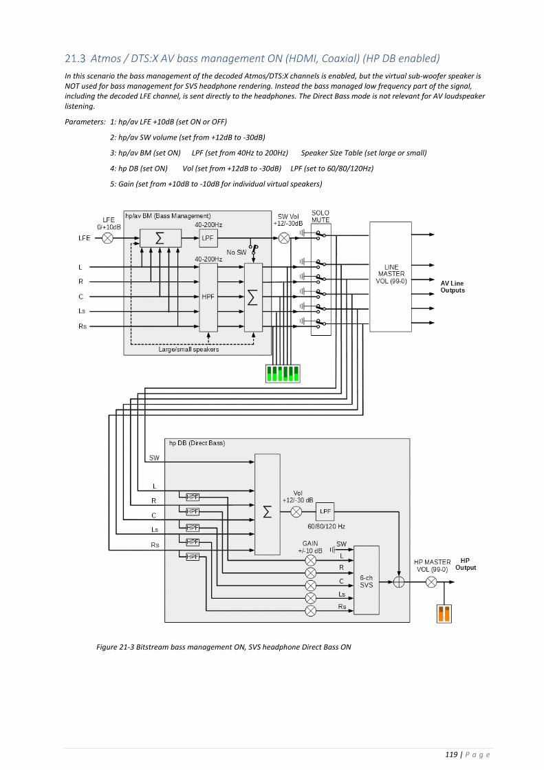
119 | P a g e
Atmos / DTS:X AV bass management ON (HDMI, Coaxial) (HP DB enabled)
In this scenario the bass management of the decoded Atmos/DTS:X channels is enabled, but the virtual sub-woofer speaker is NOT used for bass management for SVS headphone rendering. Instead the bass managed low frequency part of the signal, including the decoded LFE channel, is sent directly to the headphones. The Direct Bass mode is not relevant for AV loudspeaker listening.
Parameters: 1: hp/av LFE +10dB (set ON or OFF)
2: hp/av SW volume (set from +12dB to -30dB)
3: hp/av BM (set ON) LPF (set from 40Hz to 200Hz) Speaker Size Table (set large or small)
4: hp DB (set ON) Vol (set from +12dB to -30dB) LPF (set to 60/80/120Hz)
5: Gain (set from +10dB to -10dB for individual virtual speakers)
Figure 21-3 Bitstream bass management ON, SVS headphone Direct Bass ON

120 | P a g e
Atmos / DTS:X AV bass management OFF (HDMI, Coaxial) (HP DB enabled)
In this scenario the bass management of the decoded Atmos/DTS:X channels is disabled, and the virtual sub-woofer speaker is NOT used for bass management. Instead the bass managed part of the signal, including the decoded LFE channel, is output directly to the headphones. The Direct Bass mode is not relevant for AV loudspeaker listening.
Parameters: 1: hp/av LFE +10dB (set ON or OFF)
2: hp/av SW volume (set from +12db to -30dB)
3: hp/av BM (set OFF) LPF (not used) Speaker Size Table (not used)
4: hp DB (set ON) Vol (set from +12dB to -30dB) LPF (set to 60/80/120Hz)
5: Gain (set from +10dB to -10dB for individual virtual speakers)
Figure 21-4 Bitstream bass management OFF, SVS headphone Direct Bass ON

121 | P a g e
PCM ‘Direct’ bass management (USB, Line)
In this scenario the virtual sub-woofer speaker is NOT used for bass management. The bass managed part of the signal is output directly to the headphones.
NOTE: For PCM listening rooms there is NO bass management for AV loudspeaker outputs. The AV line output signals are output immediately after the SOLO/MUTE function.
Parameters: 1: hp LFE +10dB (set ON or OFF)
2: hp SW volume (set from +12dB to -30dB)
3: hp BM (set to DIRECT) Vol (set from +12dB to -30dB) LPF (set 60/80/120Hz)
4: Gain (set from +10dB to -10dB for individual virtual speakers)
Figure 21-5 PCM bass management OFF, SVS headphone Direct Bass ON.
Figure 21-6 Bass management for a PCM configured listening room. The hp bass management is set to Virtual. There is no bass management for the AV line outputs. The metering points for the level meters are also indicated.Figure 21-7 Bass management of a PCM configured listening room. The hp bass management is set to Direct. There is no bass management for the AV line outputs. The metering points for the level meters are also indicated.
Figure 21-8 PCM bass management OFF, SVS headphone Direct Bass ON.
Figure 21-9 Bass management for a PCM configured listening room. The hp bass management is set to Virtual. There is no bass management for the AV line outputs. The metering points for the level meters are also indicated.Figure 21-10 Bass management of a PCM configured listening room. The hp bass management is set to Direct. There is no bass management for the AV line outputs. The metering points for the level meters are also indicated.

122 | P a g e
PCM ‘Virtual’ bass management (USB, Line)
In this scenario the bass managed part of the signal is passed through to the virtual sub-woofer speaker for headphone rendering. The AV line output signals are output immediately after the SOLO/MUTE function.
NOTE: For PCM listening rooms there is NO bass management for AV loudspeaker outputs. The AV line output signals are output immediately after the SOLO/MUTE function.
Parameters: 1: hp LFE +10dB (set ON or OFF)
2: hp SW volume ( set from +12dB to -30dB)
3: hp BM (set to VIRTUAL) Vol (set from +12dB to -30dB) LPF (set 60/80/120Hz)
4: Gain (set from +10dB to -10dB for individual virtual speakers)
Figure 21-6 PCM bass management OFF, SVS headphone bass management ON.

123 | P a g e
PCM bass management ‘OFF’
In this scenario bass management is disabled, and the LFE channel is passed to the virtual sub-woofer speaker for headphone rendering.
NOTE: For PCM listening rooms there is NO bass management for AV loudspeaker outputs. The AV line output signals are output immediately after the SOLO/MUTE function.
Figure 21-7 PCM bass management OFF, SVS headphone bass management OFF.

124 | P a g e
22 Appendix K: Tactile management (all inputs) The tactile output is a two-channel, low-frequency output intended for vibration transducers to simulate body-conducted sound and acoustic vibration. The tactile signal is created by summing together one or more of the decoded or PCM signals, summing this with the rendered headphone output, and then low-pass filtering the final output.
For the tactile parameters listed below the first Vol is the volume set immediately following the tactile summation block, the second Vol is the volume of the SVS headphone signal summed into the tactile output, and LPF is the corner frequency of the low-pass filter operating on the final output.
Parameters: 1: Tactile (set ON) Vol (set from +12dB to -30dB) Vol (set from +12dB to -30dB) LPF (set 60/80/120Hz)
2. Tactile summation block (use ENTER command). Within the tactile mixing block (Figure 22-2) each input channel can be enabled or disabled, the gain of each enabled signal can be set from +10db to -6dB, and the signal can be sent to either the left, right or left+right tactile outputs.
NOTE: When enabled, the tactile signal is output from the Tactile Out phono connectors on the back panel of the Realiser A16.
Figure 22-1 Tactile output enabled. The tactile summation block is reached through the ENTER command
Figure 22-2 Tactile summation block. Any group of channels, with different gains, can be summed into the left, right or left+right tactile output.
Figure 22-3 Generation of the Tactile Output signal.
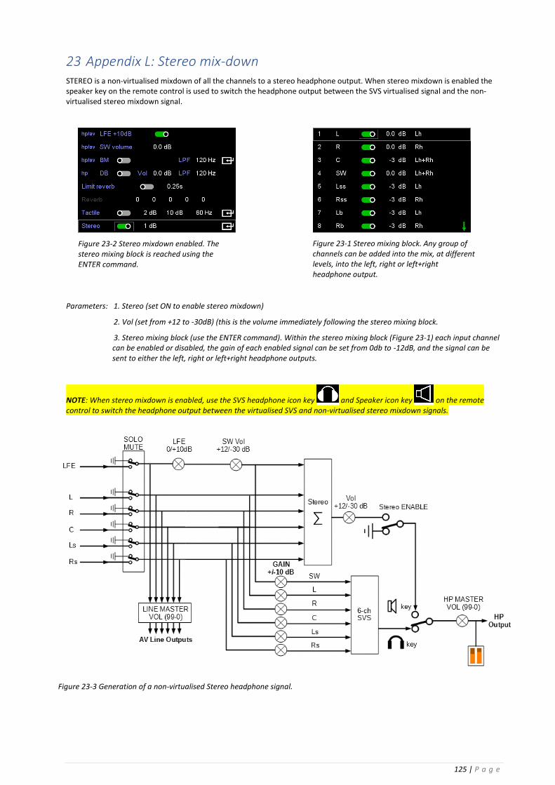
125 | P a g e
23 Appendix L: Stereo mix-down STEREO is a non-virtualised mixdown of all the channels to a stereo headphone output. When stereo mixdown is enabled the speaker key on the remote control is used to switch the headphone output between the SVS virtualised signal and the non-virtualised stereo mixdown signal.
Parameters: 1. Stereo (set ON to enable stereo mixdown)
2. Vol (set from +12 to -30dB) (this is the volume immediately following the stereo mixing block.
3. Stereo mixing block (use the ENTER command). Within the stereo mixing block (Figure 23-1) each input channel can be enabled or disabled, the gain of each enabled signal can be set from 0db to -12dB, and the signal can be sent to either the left, right or left+right headphone outputs.
NOTE: When stereo mixdown is enabled, use the SVS headphone icon key and Speaker icon key on the remote control to switch the headphone output between the virtualised SVS and non-virtualised stereo mixdown signals.
Figure 23-2 Stereo mixdown enabled. The stereo mixing block is reached using the ENTER command.
Figure 23-1 Stereo mixing block. Any group of channels can be added into the mix, at different levels, into the left, right or left+right headphone output.
Figure 23-3 Generation of a non-virtualised Stereo headphone signal.

126 | P a g e
24 Appendix M: Manual Headphone EQ
Manual headphone EQ using an external loudspeaker as reference
Manual headphone EQ using an equal loudness curve
Figure 24-1 Manual headphone EQ using an external loudspeaker as reference.
Figure 24-2 Manual headphone EQ using an equal loudness curve.

127 | P a g e
25 Appendix N: Tri-volume headphone output Move to: Home Page menu: Settings menu: System menu: Volume settings menu: Tri-vol The Tri-vol option, when enabled, allows the headphone volume to be switched quickly between three volume levels, using the rocker button on the remote control. Tri-volume only operates on the User A headphone output. It does not affect User B headphone output or the volume of the line outputs. The three levels are set by the user with the front panel volume knob for User A to change the value (rotating the knob) and to set the new value (pushing in the knob momentarily), and are stored as parameters for each preset. The initial default values for each preset are set to 62 for all three levels. If Tri-vol is enabled the active volume and volume number are displayed in the speaker-map display (Figure 25-1).
The tri-level volume levels are only accessed using the rocker button for User A on the remote control. The volume at each level can still be changed incrementally using the volume knob, and this change will display as red in the speaker map display (Figure 25-3). Using the remote control will cause the volume to revert to the tri-volume values.
Figure 25-2 Tri-vol option in the Volume settings menu.
Figure 25-1 Volume 1 set to the value 79
Figure 25-4 Changing and setting the value for the first volume level of the Tri-vol option is done through the front-panel volume knob for User A. Use the remote control volume rocker button to switch between the three levels.
Figure 25-3 If a Tri-vol level is changed using the front-panel volume knob, the newly adjusted volume is displayed in red to indicate that this is not one of the Tri-vol values.

128 | P a g e
26 Appendix O: Diagnostic displays
Audio source diagnostics
The audio source diagnostics screen is activated from the Home Page menu using the ENTER command while selecting the Audio Source option. Press the BACK key to return to the Home Page menu.
Preset speaker map information
The preset speaker map has two associated diagnostics screens, one providing information on the listening mode and the second detailing the linkage between the multichannel line outputs and the speaker labels.
26.2.1 Listening mode and multichannel line outputs
The listening mode diagnostics screen is activated from the preset speaker map display through the UP ARROW key on the remote control (Figure 26-4). The display will automatically revert to the speaker map display after a few seconds, or can be manually returned using the DOWN ARROW key. User A and User B have separate listening mode diagnostics.
The multichannel line output diagnostics screen is activated from the preset speaker map display through the DOWN ARROW icon key on the remote control (Figure 26-5). The display will automatically revert to the speaker map display after a few seconds, or can be manually returned using the UP ARROW icon key.
Figure 26-1 Audio source diagnostics screen. Figure 26-2 Activating the audio source diagnostics display through the Audio Source option on the Home Page menu.
Figure 26-3 Preset speaker map display for User A
Figure 26-4 Listening mode diagnostics for User AFigure 26-5 Preset speaker map display for User A
Figure 26-6 Preset speaker map display for User A
Figure 26-7 Listening mode diagnostics for User AFigure 26-8 Preset speaker map display for User A

129 | P a g e
Audio input and output levels
The Audio Meters display is accessible from the Home Page menu, and shows the levels of the source audio signals at the input of the SVS headphone rendering DSP for either User A or User B.
These audio signals can be from any of the input sources, such as Dolby Atmos, USB or Line. The speaker labels are taken from the active listening room for the active preset for each user..
This diagnostics screen can be used to set the analogue line input levels to -20dB referenced to a full-scale digital input signal.
The levels of the headphone output and tactile output for each user are also displayed.
Figure 26-4 Listening mode diagnostics for User A
Figure 26-5 Multichannel line output diagnostics.
Figure 26-6 Audio input and output level meters.


![· LP!a16 aL13!a16 uap]am at13!a16 uaqeq Lia-weqo uaL13!a16 vpewsuacvy wap Jne Llaqeq aauupw pun uano.lå a.z sea 99 L zips .sqv E uano.lå pun aauupw . Created Date: 20190524090803Z](https://static.fdocuments.us/doc/165x107/5d667ab488c993a7148baa9e/-lpa16-al13a16-uapam-at13a16-uaqeq-lia-weqo-ual13a16-vpewsuacvy-wap-jne.jpg)