Real-Time System Requirements & Design Specs Shaw - Chapters 3 & 4 Homework #2: 3.3.1, 3.4.1, Add...
28
Real-Time System Requirements & Design Specs Shaw - Chapters 3 & 4 Homework #2: 3.3.1, 3.4.1, Add Error states to Fig 4.1 Lecture 4/17
-
date post
22-Dec-2015 -
Category
Documents
-
view
214 -
download
0
Transcript of Real-Time System Requirements & Design Specs Shaw - Chapters 3 & 4 Homework #2: 3.3.1, 3.4.1, Add...

Real-Time SystemRequirements & Design Specs
Shaw - Chapters 3 & 4
Homework #2: 3.3.1,
3.4.1,
Add Error states to Fig 4.1
Lecture 4/17
The Problem• We need to be able to describe a system
unambiguously and prove that it can meet desired criteria before we begin the design.
• Unfortunately the reality is that for almost all practical systems, the complexity and the scale of the system makes this extremely difficult if not virtually impossible, at least with today’s tools and methodologies.
• Concurrency can easily produce race conditions. Mutual exclusion solutions can produce deadlocks or starvation. Etc.

Practical Approaches?
• Behaviors for many scenarios of interest can be demonstrated through simulation or prototyping.
• Executable “specifications” can be useful for clarifying or refining requirements and designs.
• Bottom up approaches often allow designs to evolve through increasingly adding complexity to proven simplified models and subsystems.

Imperative vs Declarative Specs
• Imperative specs specify system behaviors in terms of algorithmic descriptions. These can be visualized and translated into computer procedures and prototypes, supporting rapid prototyping.

Imperative vs Declarative Specs• Declarative descriptions specify properties
that must be satisfied by the system. It is usually easier to prove properties with these descriptions, but more difficult to use them to generate designs.
• Declarative descriptions specify properties that must be satisfies by the system. It is usually easier to prove properties with these descriptions, but more difficult to use them to generate designs.

Some Approaches Shaw Explores
• Data Flow Diagrams: Provides an attractive visualization which can be easily developed and evolved by a team.
• Tabular Languages: Provides a way to express and communicate a lot of requirements in a comprehensive and complete process.
• State Machines: State machines have proven to be a language of choice for many traditional modeling and design projects. A number of adaptations have been proposed and used effectively in real-time system designs.

Some Approaches Shaw Explores
• Formal Methods: Sophisticated mathematical techniques can provide powerful description and verification of systems, for example:– Regular expressions– Propositional Logic– Predicates– Temporal Logic

Data Flow Diagrams
• They are based on a familiar tool
• They provide an attractive visualization which can be easily developed and evolved by a team.
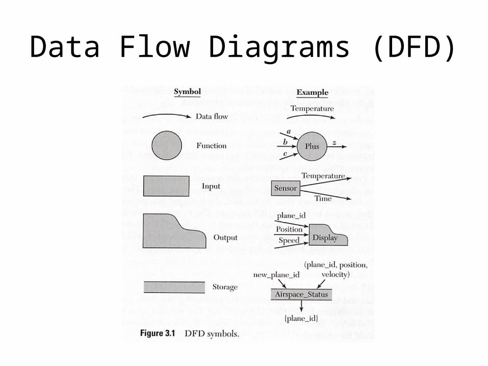
Data Flow Diagrams (DFD)

DFD Example

DFD Example

DFD Deficiencies
• Lack of control information
• Lack of timing
• Lack of scheduling specification

Tabular languages
• They provide a way to express and communicate a lot of requirements in a comprehensive and complete process.
• They nicely tabulate Conditions and Actions
• They are easily expanded, partitioned, and simplified.

Tabular Languages

Example of Tabular Language

Example Tabular Language

Tabular Language Deficiencies
• Timing and logical constraints are listed separately
• There does not appear to be an obvious way to include concurrency and timing in an effective way.

Finite State Machines
• State machines have proven to be a language of choice for many traditional modeling and design projects. A number of adaptations have been proposed and used effectively in real-time system designs.
• We will look at one approach Communicating Real-Time State Machines (CRSM)

FSM Example
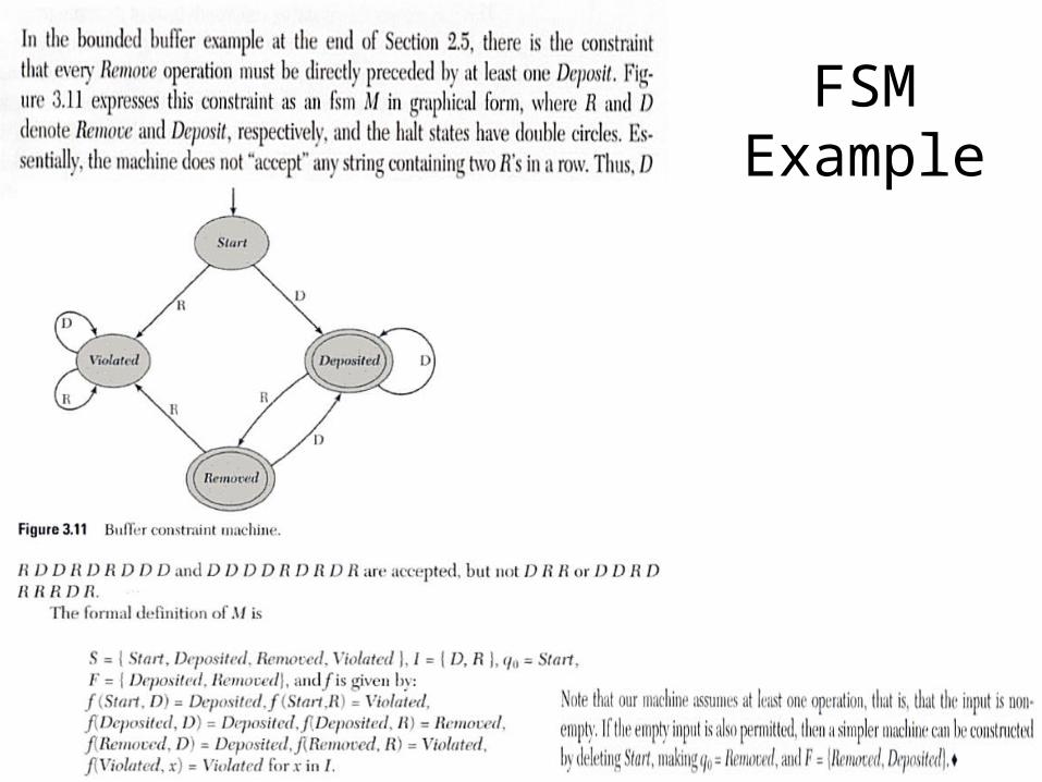
FSM Example
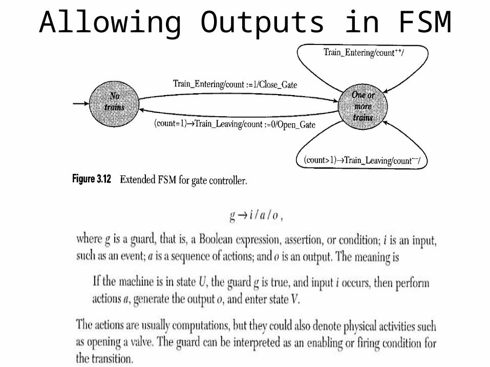
Allowing Outputs in FSM

Chapter 4 Systems of State Machines
• Communicating Real-Time State Machines
• An attempt to create a complete executable design specification language
• Time is integral to the language
CRSMs
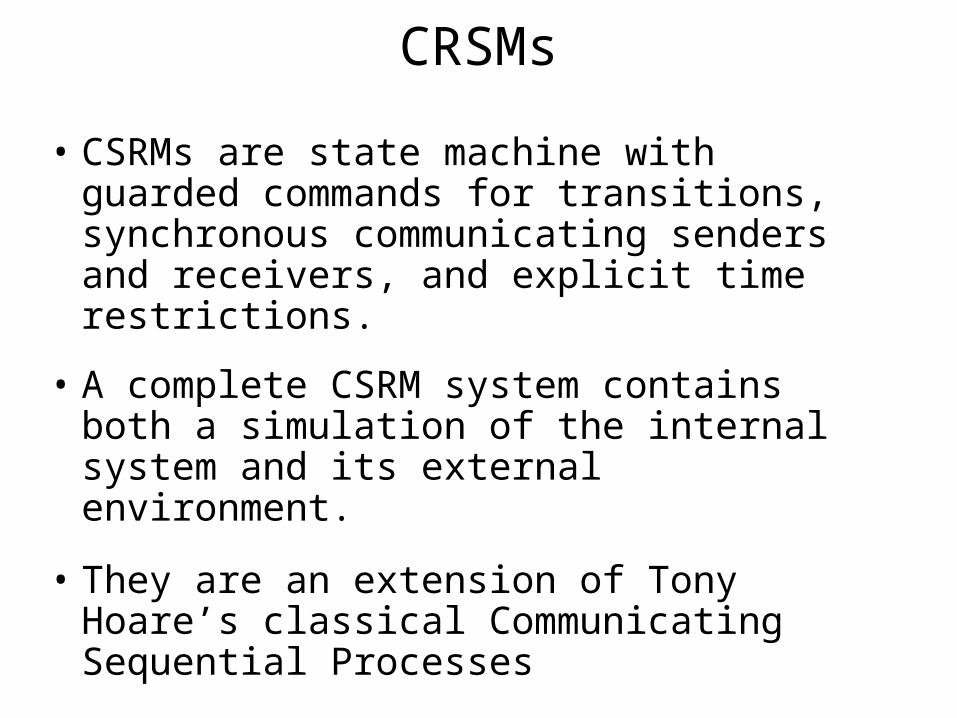
• CSRMs are state machine with guarded commands for transitions, synchronous communicating senders and receivers, and explicit time restrictions.
• A complete CSRM system contains both a simulation of the internal system and its external environment.
• They are an extension of Tony Hoare’s classical Communicating Sequential Processes

Terminology
Denotes the timing constraint, i.e. the lower tmin and upper tmax bounds on time allowed during the transition. Then for an execution or deadline d,
0 <= tmin <= d <= tmax
Terminology
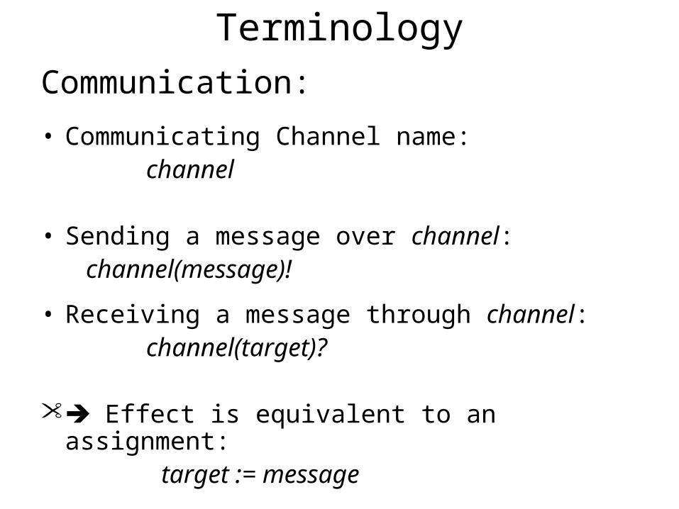
Communication:
• Communicating Channel name: channel
• Sending a message over channel: channel(message)!
• Receiving a message through channel: channel(target)?
Effect is equivalent to an assignment: target := message

CRSM Timing
M1 (sender) enters state U at time Tu, and M2 (Receiver) enters state X at Tx :
I/O must occur between Tu+a and Tx+d or CRSM will transition to an error state

Bounded Buffer Example

Mouse Click Example